EP2840049A1 - Vorrichtung zum Transportieren eines Prospekts - Google Patents
Vorrichtung zum Transportieren eines Prospekts Download PDFInfo
- Publication number
- EP2840049A1 EP2840049A1 EP13004109.8A EP13004109A EP2840049A1 EP 2840049 A1 EP2840049 A1 EP 2840049A1 EP 13004109 A EP13004109 A EP 13004109A EP 2840049 A1 EP2840049 A1 EP 2840049A1
- Authority
- EP
- European Patent Office
- Prior art keywords
- brochure
- clamping
- pliers
- stationary
- lever
- Prior art date
- Legal status (The legal status is an assumption and is not a legal conclusion. Google has not performed a legal analysis and makes no representation as to the accuracy of the status listed.)
- Granted
Links
Images


Classifications
-
- B—PERFORMING OPERATIONS; TRANSPORTING
- B65—CONVEYING; PACKING; STORING; HANDLING THIN OR FILAMENTARY MATERIAL
- B65H—HANDLING THIN OR FILAMENTARY MATERIAL, e.g. SHEETS, WEBS, CABLES
- B65H29/00—Delivering or advancing articles from machines; Advancing articles to or into piles
- B65H29/02—Delivering or advancing articles from machines; Advancing articles to or into piles by mechanical grippers engaging the leading edge only of the articles
- B65H29/04—Delivering or advancing articles from machines; Advancing articles to or into piles by mechanical grippers engaging the leading edge only of the articles the grippers being carried by endless chains or bands
- B65H29/045—Details of grippers
-
- B—PERFORMING OPERATIONS; TRANSPORTING
- B65—CONVEYING; PACKING; STORING; HANDLING THIN OR FILAMENTARY MATERIAL
- B65H—HANDLING THIN OR FILAMENTARY MATERIAL, e.g. SHEETS, WEBS, CABLES
- B65H5/00—Feeding articles separated from piles; Feeding articles to machines
- B65H5/08—Feeding articles separated from piles; Feeding articles to machines by grippers, e.g. suction grippers
- B65H5/14—Details of grippers; Actuating-mechanisms therefor
-
- B—PERFORMING OPERATIONS; TRANSPORTING
- B65—CONVEYING; PACKING; STORING; HANDLING THIN OR FILAMENTARY MATERIAL
- B65H—HANDLING THIN OR FILAMENTARY MATERIAL, e.g. SHEETS, WEBS, CABLES
- B65H2402/00—Constructional details of the handling apparatus
- B65H2402/50—Machine elements
- B65H2402/54—Springs, e.g. helical or leaf springs
-
- B—PERFORMING OPERATIONS; TRANSPORTING
- B65—CONVEYING; PACKING; STORING; HANDLING THIN OR FILAMENTARY MATERIAL
- B65H—HANDLING THIN OR FILAMENTARY MATERIAL, e.g. SHEETS, WEBS, CABLES
- B65H2405/00—Parts for holding the handled material
- B65H2405/50—Gripping means
- B65H2405/58—Means for achieving gripping/releasing operation
- B65H2405/5812—Means for achieving gripping/releasing operation pivoting the movable gripping part towards the other part
Definitions
- the invention relates to a device for transporting a leaflet.
- Brochures are for example the leaflets or instructions for use of medicines, cosmetics and toiletries.
- the folded leaflets are transported individually and combined with the corresponding product so that usually a simultaneous insertion into the appropriate packaging is possible.
- the devices generally have an endlessly circulating transport device, which may be designed, for example, as a circulating transport chain.
- the transport device has a plurality of prospective tongs, which are arranged at regular intervals on the transport device.
- the respective brochure pliers After being fitted with a brochure, the respective brochure pliers are closed, so that the brochure is held firmly by the brochure pliers. During transport of the leaflet, this can for example be prefolded by deflection profiles, so that the prospectus finally has an approximately U-shaped form.
- the brochure is placed between the packaging and the product to be packaged. In this way, the product can virtually take the brochure when inserted into the packaging.
- the folder tongs must be opened to allow the brochure to be taken. The opened brochure tongs are then over the circulating transport device transported back to be equipped with another brochure.
- the brochure pliers known in the prior art are in their rest position in a closed position. In this rest position, the brochure tongs are held closed by spring force.
- the brochure tweezers are opened regularly via a turnout system. Leaves the brochure pliers the area of the switch system, closes the brochure pliers automatically again.
- the present invention seeks to provide an improved device for transporting a brochure, which has a compact design and the lowest possible susceptibility.
- the device according to the invention for transporting a leaflet has an endlessly circulating transport device, on which at least one leaflet tongs are arranged.
- the brochure tongs is designed as a self-retaining forceps.
- the use of a self-holding brochure pliers with static positions allows the use of very short switch systems, which must put the brochure pliers only in the open or closed state, without having to maintain this state.
- technically simple turnout systems can be used, which often leads to less wear and longer maintenance intervals.
- a particularly compact brochure transport device can be made possible by short, simple switch systems.
- the prospectus is clamped between two clamping units of the brochure pliers and thereby held. At least one of the two clamping units can be adjusted by the switches between at least two positions, so that opening and closing of the brochure pliers is possible.
- one of the two clamping units is stationary, so that only one clamping unit has to be adjusted by the switches. This reduces the number of components required, in particular the moving components, which regularly leads to lower susceptibility to interference.
- the at least one adjustable clamping unit may preferably comprise a clamping lever, which is pivotally mounted on a stationary pliers block.
- the clamping lever can be fixed in position by a toggle lever by means of a spring-loaded punch in two positions. In this way, a self-holding brochure pliers is realized in a structurally particularly simple and economical way.
- the spring of the spring-loaded punch may be formed in a particularly preferred embodiment as a plate spring package.
- the use of disc springs increases the maintenance intervals compared to conventional tension or compression springs many times, so that a particularly economical operation of the device according to the invention is possible.
- clamping lever On the clamping lever may preferably be provided a shoulder element which allows an adjustment of the position of the clamping lever.
- a switch can act on this shoulder element to adjust the position of the clamping lever.
- the short switch can be adjusted so that it does not attack the shoulder element and the folder pliers remain closed.
- the leaflet may slippage and thus become jammed in the brochure pliers, which would necessitate a manual removal thereof. This would mean a stoppage of the product transport device and thus also of the packaging device.
- one of the two clamping units may have a concave clamping region and the other of the two clamping units may have a convex clamping region.
- the stationary clamping unit may have a concave clamping area
- the adjustable clamping unit may have a convex clamping area.
- the convex clamping region may be formed in a structurally particularly simple embodiment as a round rod.
- the two clamping units can preferably be arranged approximately horizontally, so that the brochure can be transported approximately horizontally.
- the lower or the upper edge region of the brochure can already be in the position in which the brochure is present in the packaging. This facilitates the insertion of product and brochure into the packaging, so that higher web speeds and shorter packaging paths are possible.
- the free end of the prospectus flexes slightly downward by gravity, so that in an arrangement of the brochure transport device above the products to be inserted only a bending of the lower free end of the prospectus in a likewise approximately horizontal position is necessary to the prospectus for to fold in the packaging.
- folder tongs can be present on a device according to the invention, which are each arranged at regular intervals on the transport device.
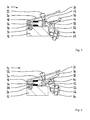
- a non-illustrated device for transporting a leaflet has an endlessly circulating transport device to which a plurality of prospective tongs 10 are present.
- the brochure tongs 10 are designed as self-holding forceps. In the Fig. 1 to 3 the brochure tong 10 is shown in its open position 70; in the 4 to 6 while in its closed position 72.
- the claw pliers 10 has a stationary pliers block 12.
- the pliers block 12 has at its lower edge region a mounting plate 14.
- On the mounting plate 14 are in the present example, two fastening webs 16 via two screws 18th attached.
- the brochure pliers 10 can be attached to a transport device not shown in the figures.
- a stationary first clamping unit 20 is attached via a screw 22.
- the stationary clamping unit 20 is oriented approximately horizontally, wherein the deviation from the horizontal in the present example case is about 15 degrees.
- the left in the drawing edge region of the clamping unit 20 is formed as a clamping portion 24.
- the clamping region 24 is slightly concave in the present example.
- the width of the clamping region 24 is chosen so large that the leaflets are held by the clamping region 24 over a large part of their width. Ideally, the leaflets should protrude only minimally beyond the clamping area 24 in order to enable safe transport with as little damage or kinking as possible.
- the adjustable second clamping unit 30 has a clamping lever 32 which is pivotally mounted on the stationary pliers block 12 via a rear axis of rotation 34.
- the clamping lever 32 has at its front edge region on a round bar 36, which serves as a concave clamping area. Between the clamping area 24 and the round bar 36, the brochure can be kept clamped when the brochure forceps 10 is in its closed position 72.
- the clamping lever 32 is mounted centrally on a toggle lever 40 via a first axis of rotation 38.
- the second axis of rotation 42 of the toggle lever 40 is mounted on a projection 44 of the stationary pliers block 12.
- the toggle lever 40 is fixed in position by a longitudinally displaceable punch 46 in its two positions.
- the punch 46 is mounted longitudinally displaceably in a bore 48 of the projection 44 in the stationary pliers block 12.
- a cup spring package 50 ensures that the punch 46 presses against the toggle 40, so that the position of the toggle lever and thus also the position of the adjustable clamping unit 30 is fixed.
- a shoulder element 60 which in the present example is circular, is fastened to the clamping lever 32 via a screw 62.
- the shoulder element 60 serves as a point of attack for the adjustment of the clamping unit 30 from its open position (see Fig. 1 to 3 ) in its closed position (see 4 to 6 ) and vice versa. This adjustment could be done manually, for example.
- the shoulder element 60 would serve as a handle element.
- the adjustment of the clamping unit 30 via a switch which pushes the shoulder member 60 upwards or downwards.
- Such turnout systems can be realized structurally simple, so that an economical use of the same is possible. At the same time, the turnout systems have only a low susceptibility to interference and can be adjusted by a slight pivoting so that no contact of the shoulder element 60 takes place with the switch, unless an adjustment of the clamping unit 30 should not be desirable.
Landscapes
- Engineering & Computer Science (AREA)
- Mechanical Engineering (AREA)
- Chain Conveyers (AREA)
Abstract
Description
- Die Erfindung betrifft eine Vorrichtung zum Transportieren eines Prospekts. Als Prospekte werden beispielsweise die Beipackzettel oder Gebrauchsanweisungen von Medikamenten, Kosmetika und Hygieneartikeln bezeichnet. Mittels einer solchen Vorrichtung werden die gefalteten Prospekte einzeln transportiert und mit dem entsprechenden Produkt so zusammengeführt, dass in der Regel ein simultanes Einschieben in die entsprechende Verpackung möglich ist.
- Vorrichtungen zum Transportieren von Prospekten sind bekannt. Die Vorrichtungen weisen in der Regel eine endlos umlaufende Transporteinrichtung auf, die beispielsweise als umlaufende Transportkette ausgebildet sein kann. Die Transporteinrichtung weist mehrere Prospektzangen auf, die in gleichmäßigen Abständen an der Transporteinrichtung angeordnet sind.
- Nach der Bestückung mit einem Prospekt wird die jeweilige Prospektzange geschlossen, so dass der Prospekt fest von der Prospektzange gehalten wird. Während des Transports des Prospekts kann dieser beispielsweise von Umlenkprofilen vorgefaltet werden, so dass der Prospekt schließlich eine etwa U-förmige Gestalt aufweist. Im Verlauf des Transports wird der Prospekt zwischen der Verpackung und dem zu verpackenden Produkt platziert. Auf diese Weise kann das Produkt beim Einschieben in die Verpackung den Prospekt quasi mitnehmen. Beim diesem Einschieben des Produkts muss die Prospektzange geöffnet werden, um das Mitnehmen des Prospekts zu ermöglichen. Die geöffneten Prospektzangen werden anschließend über die umlaufende Transporteinrichtung zurücktransportiert, um mit einem weiteren Prospekt bestückt zu werden.
- Die im Stand der Technik bekannten Prospektzangen befinden sich in ihrer Ruhestellung in einer geschlossenen Stellung. In dieser Ruhestellung werden die Prospektzangen über Federkraft geschlossen gehalten. Das Öffnen der Prospektzangen erfolgt regelmäßig über ein Weichensystem. Verlässt die Prospektzange den Bereich des Weichensystems, schließt sich die Prospektzange automatisch wieder.
- Sofern das Verpacken des Produkts und damit auch der Transport der Prospekte taktweise erfolgt, ist eine einzelne Weiche zum Öffnen der Prospektzange im Bereich der Bestückung der Prospektzange und im Bereich der Übergabe des Prospekts in die Verpackung ausreichend. Um die Produktivität der Verpackungsvorrichtung zu erhöhen, wird oftmals ein kontinuierliches Verfahren beim Einschieben des Produkts und damit auch des Prospekts in die Verpackung eingesetzt. Dadurch sind lange Weichensysteme erforderlich, die die Prospektzange für die Bestückung und insbesondere für die Übergabe des Prospekts zur Verpackung für eine längere Strecke offen halten. Die Transportvorrichtungen für die Prospekte bauen dementsprechend groß. Sofern ein Öffnen der Prospektzange verhindert werden soll - beispielsweise bei fehlender Verpackung - sind eine Vielzahl von kleinen, direkt hintereinander vorhandenen Weichen erforderlich, was einen hohen Steuerungsaufwand und eine große Störanfälligkeit mit sich bringt.
- Ausgehend von diesem vorbekannten Stand der Technik liegt der Erfindung die Aufgabe zugrunde, eine verbesserte Vorrichtung zum Transportieren eines Prospekt anzugeben, die eine kompakte Bauweise und eine möglichst geringe Störanfälligkeit aufweist.
- Die erfindungsgemäße Vorrichtung ist durch die Merkmale des Hauptanspruchs 1 gegeben. Sinnvolle Weiterbildungen der Erfindung sind Gegenstand von sich an den Hauptanspruch anschließenden weiteren Ansprüchen.
- Die erfindungsgemäße Vorrichtung zum Transportieren eines Prospekts besitzt eine endlos umlaufende Transporteinrichtung, an der zumindest eine Prospektzange angeordnet ist. Erfindungsgemäß ist die Prospektzange als selbsthaltende Zange ausgebildet. Die Verwendung einer selbsthaltenden Prospektzange mit statischen Positionen erlaubt den Einsatz von sehr kurzen Weichensystemen, welche die Prospektzange lediglich in den geöffneten oder den geschlossenen Zustand versetzen müssen, ohne diesen Zustand aufrechterhalten zu müssen. Dadurch können technisch einfache Weichensysteme eingesetzt werden, was oftmals zu geringerem Verschleiß und längeren Wartungsintervallen führt. Darüber hinaus kann durch kurze, einfache Weichensysteme eine besonders kompakte Prospekttransportvorrichtung ermöglicht werden.
- Sofern ein Öffnen der Prospektzange verhindert werden soll - beispielsweise bei fehlender Verpackung - muss lediglich diese kurze Weiche ausweichen, so dass keine Vielzahl von kleinen, hintereinander geschalteter Weichen erforderlich ist. Entsprechend verringert sich die Stör- und Wartungsanfälligkeit des Weichensystems und damit auch der Prospekttransportvorrichtung.
- Der Prospekt wird zwischen zwei Klemmeinheiten der Prospektzange eingeklemmt und dadurch gehalten. Zumindest eine der beiden Klemmeinheiten kann von den Weichen zwischen zumindest zwei Positionen verstellt werden, so dass ein Öffnen und Schließen der Prospektzange möglich ist.
- Vorzugsweise ist eine der beiden Klemmeinheiten stationär ausgebildet, so dass lediglich eine Klemmeinheit durch die Weichen verstellt werden muss. Dies reduziert die Anzahl der benötigten Bauteile, insbesondere der beweglichen Bauteile, was regelmäßig zu geringerer Störanfälligkeit führt.
- Die zumindest eine verstellbare Klemmeinheit kann vorzugsweise einen Klemmhebel aufweisen, der schwenkbar an einem stationären Zangenblock gelagert ist. Der Klemmhebel kann über einen Kniehebel mittels eines gefederten Stempels in zwei Positionen lagefixiert werden. Auf diese Weise wird in einer konstruktiv besonders einfachen und wirtschaftlichen Art eine selbsthaltende Prospektzange verwirklicht.
- Die Feder des gefederten Stempel kann in einer besonders bevorzugten Ausführungsform als Tellerfederpaket ausgebildet sein. Die Verwendung von Tellerfedern vergrößert die Wartungsintervalle gegenüber herkömmlichen Zug- oder Druckfedern um ein Vielfaches, so dass ein besonders wirtschaftlicher Betrieb der erfindungsgemäßen Vorrichtung möglich ist.
- An dem Klemmhebel kann vorzugsweise ein Schulterelement vorhanden sein, das eine Verstellung der Position des Klemmhebels ermöglicht. An diesem Schulterelement kann somit eine Weiche angreifen, um die Position des Klemmhebels zu verstellen.
- Sofern der Prospekt nicht in eine Verpackung eingeschoben werden kann, beispielsweise weil das zu verpackende Produkt oder die Verpackung selbst fehlerhaft oder nicht vorhanden sind, kann die kurze Weiche so verstellt werden, dass diese nicht an dem Schulterelement angreift und die Prospektzange geschlossen bleibt. Bei einem Öffnen der Prospektzange könnte es in einem solchen Fall nämlich zu einem Verrutschen des Prospekts und damit zu einem Verkanten desselben in der Prospektzange kommen, was ein manuelles Entfernen desselben erforderlich machen würde. Dies würde einen Stillstand der Produkttransportvorrichtung und damit auch der Verpackungsvorrichtung bedeuten. Durch den Einsatz der selbsthemmenden Prospektzange ist ein Ausweichen der Weiche zum Öffnen der Prospektzange auf einfache Weise und mit großer Zuverlässigkeit möglich, so dass derartige Störfälle effektiv vermieden werden können.
- Um ein möglichst schonendes Greifen und Transportieren des Prospekts zu ermöglichen, kann eine der beiden Klemmeinheiten einen konkaven Klemmbereich und die andere der beiden Klemmeinheiten einen konvexen Klemmbereich aufweisen. Insbesondere kann die stationäre Klemmeinheit einen konkaven Klemmbereich aufweisen, während die verstellbare Klemmeinheit einen konvexen Klemmbereich aufweisen kann. Der konvexe Klemmbereich kann in einer konstruktiv besonders einfachen Ausführungsform als Rundstab ausgebildet sein.
- Die beiden Klemmeinheiten können vorzugsweise etwa horizontal angeordnet sein, so dass der Prospekt etwa horizontal transportiert werden kann. Auf diese Weise kann sich der untere oder der obere Randbereich des Prospekts - je nachdem, ob die Prospekttransportvorrichtung oberhalb oder unterhalb der Produktkette befindet - bereits in derjenigen Position befinden, in der der Prospekt in der Verpackung vorliegt. Dies erleichtert das Einschieben von Produkt und Prospekt in die Verpackung, so dass höhere Bahngeschwindigkeiten und kürzere Verpackungswege möglich sind. Darüber hinaus biegt sich das freie Ende des Prospekts durch die Schwerkraft leicht nach unten, so dass bei einer Anordnung der Prospekttransportvorrichtung oberhalb der einzuschiebenden Produkte lediglich noch ein Umbiegen des unteren freien Endes des Prospekts in eine ebenfalls etwa horizontale Lage notwendig ist, um den Prospekt für das Einschieben in die Verpackung vorzufalten.
- In der Regel können mehrere Prospektzangen an einer erfindungsgemäßen Vorrichtung vorhanden sein, die jeweils in regelmäßigen Abständen an der Transporteinrichtung angeordnet sind.
- Weitere Vorteile und Merkmale der Erfindung sind den in den Ansprüchen ferner angegebenen Merkmalen sowie dem nachstehenden Ausführungsbeispiel zu entnehmen.
- Die Erfindung wird im Folgenden anhand des in der Zeichnung dargestellten Ausführungsbeispiels näher beschrieben und erläutert. Es zeigen:
- Fig. 1
- eine perspektivische Ansicht der Prospektzange der erfindungsgemäßen Vorrichtung zum Transportieren von Prospekten in ihrer geöffneten Stellung,
- Fig. 2
- eine Seitenansicht der Prospektzange gemäß
Fig. 1 , - Fig. 3
- einen Schnitt durch die Prospektzange gemäß
Fig. 1 , - Fig. 4
- einen Schnitt durch die Prospektzange gemäß
Fig. 1 in ihrer geschlossenen Stellung, - Fig. 5
- einen perspektivische Ansicht der Prospektzange gemäß
Fig. 4 und - Fig. 6
- eine Seitenansicht der Prospektzange gemäß
Fig. 4 . - Eine nicht näher dargestellte Vorrichtung zum Transportieren eines Prospekts besitzt eine endlos umlaufende Transporteinrichtung, an der mehrere Prospektzangen 10 vorhanden sind. Die Prospektzangen 10 sind dabei als selbsthaltende Zangen ausgebildet. In den
Fig. 1 bis 3 ist die Prospektzange 10 in ihrer geöffneten Position 70 dargestellt; in denFig. 4 bis 6 dagegen in ihrer geschlossenen Position 72. - Die Prospektzange 10 besitzt einen stationären Zangenblock 12. Der Zangenblock 12 besitzt an seinem unteren Randbereich eine Befestigungsplatte 14. An der Befestigungsplatte 14 sind im vorliegenden Beispielsfall zwei Befestigungsstege 16 über jeweils zwei Schrauben 18 befestigt. Über die Befestigungsplatte 14 und die Befestigungsstege 16 kann die Prospektzange 10 an einer in den Figuren nicht dargestellten Transporteinrichtung befestigt werden.
- An der Oberseite des stationären Zangenblocks 12 ist eine stationäre erste Klemmeinheit 20 über eine Schraube 22 befestigt. Die stationäre Klemmeinheit 20 ist etwa horizontal ausgerichtet, wobei die Abweichung von der Horizontalen im vorliegenden Beispielsfall etwa 15 Grad beträgt. Der in der Zeichnung linke Randbereich der Klemmeinheit 20 ist als Klemmbereich 24 ausgebildet. Der Klemmbereich 24 ist im vorliegenden Beispielsfall leicht konkav ausgebildet. Die Breite des Klemmbereichs 24 ist so groß gewählt, dass die Prospekte über einen Großteil ihrer Breite von dem Klemmbereich 24 gehalten werden. Idealerweise sollten die Prospekte lediglich minimal über den Klemmbereich 24 hinausragen, um einen sicheren Transport mit möglichst wenig Beschädigungen oder Knicken zu ermöglichen.
- Die verstellbare zweite Klemmeinheit 30 besitzt einen Klemmhebel 32, der über eine hintere Drehachse 34 an dem stationären Zangenblock 12 verschwenkbar gelagert ist. Der Klemmhebel 32 weist an seinem vorderen Randbereich einen Rundstab 36 auf, der als konkaver Klemmbereich dient. Zwischen dem Klemmbereich 24 und dem Rundstab 36 kann der Prospekt eingeklemmt gehalten werden, wenn sich die Prospektzange 10 in der ihrer geschlossenen Position 72 befindet.
- Der Klemmhebel 32 ist mittig über eine erste Drehachse 38 an einem Kniehebel 40 gelagert. Die zweite Drehachse 42 des Kniehebels 40 ist an einem Vorsprung 44 des stationären Zangenblocks 12 gelagert. Der Kniehebel 40 wird von einem längsverschieblichen Stempel 46 in seinen beiden Positionen lagefixiert. Der Stempel 46 ist in einer Bohrung 48 des Vorsprungs 44 in dem stationären Zangenblock 12 längsverschieblich gelagert. Ein Tellerfederpaket 50 sorgt dafür, dass der Stempel 46 gegen den Kniehebel 40 drückt, so dass die Position des Kniehebels und damit auch die Position der verstellbaren Klemmeinheit 30 fixiert wird.
- Unterhalb des Rundstabs 36 ist an dem Klemmhebel 32 ein im vorliegenden Beispielsfall kreisförmiges Schulterelement 60 über eine Schraube 62 befestigt. Das Schulterelement 60 dient dabei als Angriffspunkt für die Verstellung der Klemmeinheit 30 von ihrer geöffneten Position (siehe
Fig. 1 bis 3 ) in ihre geschlossene Position (sieheFig. 4 bis 6 ) und umgekehrt. Dieses Verstellen könnte beispielsweise manuell erfolgen. In diesem Fall würde das Schulterelement 60 als Griffelement dienen. Vorzugsweise erfolgt die Verstellung der Klemmeinheit 30 über eine Weiche, die das Schulterelement 60 nach oben oder nach unten drückt. Derartige Weichensystem können konstruktiv einfach verwirklicht werden, so dass ein wirtschaftlicher Einsatz derselben möglich ist. Gleichzeitig weisen die Weichensysteme nur eine geringe Störanfälligkeit auf und können über ein leichtes Verschwenken so verstellt werden, dass keine Berührung des Schulterelements 60 mit der Weiche erfolgt, sofern ein Verstellen der Klemmeinheit 30 einmal nicht gewünscht sein sollte.
Claims (9)
- Vorrichtung zum Transportieren eines Prospekts- mit einer endlos umlaufenden Transporteinrichtung,- mit zumindest einer Prospektzange (10), die an der Transporteinrichtung angeordnet ist und zwei Klemmeinheiten (20, 30) aufweist, zwischen denen der Prospekt haltbar ist,- dadurch gekennzeichnet, dass- die Prospektzange (10) als selbsthaltende Zange mit einer statischen geschlossenen Position (72) und einer statischen geöffneten Position (70) ausgebildet ist.
- Vorrichtung nach Anspruch 1,- dadurch gekennzeichnet, dass- die Prospektzange (10) eine stationäre erste Klemmeinheit (20) aufweist,- die Prospektzange (10) eine zweite Klemmeinheit (30) aufweist, die in zumindest zwei Positionen verstellbar ist.
- Vorrichtung nach Anspruch 1 oder 2,- dadurch gekennzeichnet, dass- die zumindest eine verstellbare Klemmeinheit (30) einen Klemmhebel (32) aufweist, der schwenkbar an einem stationären Zangenblock (12) gelagert ist,- der Klemmhebel (32) über einen Kniehebel (40) mittels eines gefederten Stempels (46) in zwei Positionen lagefixierbar ist.
- Vorrichtung nach Anspruch 3,- dadurch gekennzeichnet, dass- die Feder des Stempels (46) als Tellerfederpaket (50) ausgebildet ist.
- Vorrichtung nach Anspruch 3 oder 4,- dadurch gekennzeichnet, dass- an dem Klemmhebel (32) ein Schulterelement (60) vorhanden ist, mittels dem die Position des Klemmhebels (32) verstellbar ist.
- Vorrichtung nach einem der Ansprüche 2 bis 5,- dadurch gekennzeichnet, dass- die stationäre erste Klemmeinheit (20) an dem stationären Zangenblock (12) befestigt ist.
- Vorrichtung nach einem der vorstehenden Ansprüchen,- dadurch gekennzeichnet, dass- die eine der beiden Klemmeinheiten (20) einen konkaven Klemmbereich (24) aufweist,- die andere der beiden Klemmeinheiten (30) einen konvexen Klemmbereich (36) aufweist.
- Vorrichtung nach einem der vorstehenden Ansprüchen,- dadurch gekennzeichnet, dass- die beiden Klemmeinheiten (20, 30) etwa horizontal angeordnet sind.
- Vorrichtung nach einem der vorstehenden Ansprüche,- dadurch gekennzeichnet, dass- mehrere Prospektzangen (10) vorhanden sind,- die Prospektzangen (10) in regelmäßigen Abständen an der Transporteinrichtung angeordnet sind.
Priority Applications (1)
| Application Number | Priority Date | Filing Date | Title |
|---|---|---|---|
| EP13004109.8A EP2840049B1 (de) | 2013-08-20 | 2013-08-20 | Vorrichtung zum Transportieren eines Prospekts |
Applications Claiming Priority (1)
| Application Number | Priority Date | Filing Date | Title |
|---|---|---|---|
| EP13004109.8A EP2840049B1 (de) | 2013-08-20 | 2013-08-20 | Vorrichtung zum Transportieren eines Prospekts |
Publications (2)
| Publication Number | Publication Date |
|---|---|
| EP2840049A1 true EP2840049A1 (de) | 2015-02-25 |
| EP2840049B1 EP2840049B1 (de) | 2017-05-10 |
Family
ID=49033775
Family Applications (1)
| Application Number | Title | Priority Date | Filing Date |
|---|---|---|---|
| EP13004109.8A Active EP2840049B1 (de) | 2013-08-20 | 2013-08-20 | Vorrichtung zum Transportieren eines Prospekts |
Country Status (1)
| Country | Link |
|---|---|
| EP (1) | EP2840049B1 (de) |
Cited By (1)
| Publication number | Priority date | Publication date | Assignee | Title |
|---|---|---|---|---|
| DE202015006473U1 (de) | 2015-09-18 | 2015-10-12 | Harro Höfliger Verpackungsmaschinen GmbH | Transportvorrichtung, insbesondere zum Transportieren eines Prospekts |
Citations (4)
| Publication number | Priority date | Publication date | Assignee | Title |
|---|---|---|---|---|
| EP0386442A2 (de) * | 1989-03-07 | 1990-09-12 | Grapha-Holding Ag | Takttransporteur |
| WO1991007342A1 (de) * | 1989-11-08 | 1991-05-30 | Grapha-Holding Ag | Klemmzange für kettentransporteure |
| DE19642117A1 (de) * | 1996-10-12 | 1998-04-16 | Koenig & Bauer Albert Ag | Klemmzange für Endlosförderer |
| CH690301A5 (de) * | 1995-10-03 | 2000-07-14 | Ferag Ag | Klammer und Transportvorrichtung für flächige Gegenstände. |
-
2013
- 2013-08-20 EP EP13004109.8A patent/EP2840049B1/de active Active
Patent Citations (4)
| Publication number | Priority date | Publication date | Assignee | Title |
|---|---|---|---|---|
| EP0386442A2 (de) * | 1989-03-07 | 1990-09-12 | Grapha-Holding Ag | Takttransporteur |
| WO1991007342A1 (de) * | 1989-11-08 | 1991-05-30 | Grapha-Holding Ag | Klemmzange für kettentransporteure |
| CH690301A5 (de) * | 1995-10-03 | 2000-07-14 | Ferag Ag | Klammer und Transportvorrichtung für flächige Gegenstände. |
| DE19642117A1 (de) * | 1996-10-12 | 1998-04-16 | Koenig & Bauer Albert Ag | Klemmzange für Endlosförderer |
Cited By (1)
| Publication number | Priority date | Publication date | Assignee | Title |
|---|---|---|---|---|
| DE202015006473U1 (de) | 2015-09-18 | 2015-10-12 | Harro Höfliger Verpackungsmaschinen GmbH | Transportvorrichtung, insbesondere zum Transportieren eines Prospekts |
Also Published As
| Publication number | Publication date |
|---|---|
| EP2840049B1 (de) | 2017-05-10 |
Similar Documents
| Publication | Publication Date | Title |
|---|---|---|
| EP3682050B1 (de) | Fördereinrichtung für eine faltvorrichtung zum falten von textilien | |
| EP2113462A1 (de) | Vorrichtung zum Handhaben von flexiblen Beuteln | |
| WO2012139538A1 (de) | Kurvengurtförderer und halteelement mit rollen für einen kurvengurtförderer | |
| CH618399A5 (de) | ||
| CH677652A5 (de) | ||
| EP1736412B1 (de) | Clipmaschine | |
| DE19536692A1 (de) | Transportstern für Gefäße | |
| EP2840049B1 (de) | Vorrichtung zum Transportieren eines Prospekts | |
| DE102007012778B4 (de) | Einstellbarer Clipvorschub | |
| EP1244593A2 (de) | Vorrichtung zum transport eines flächigen warenstückes | |
| DE102015010420B3 (de) | Warentrennvorrichtung | |
| AT516092A1 (de) | Vorrichtung und Verfahren zum Transport von schlauchförmigen Sackkörpern | |
| EP2796394B1 (de) | Verstellbarer Klammerstern | |
| EP2206668B1 (de) | Vorrichtung und Verfahren zum Transfer von flexiblen flachen Gegenständen | |
| EP2367745B1 (de) | Vorrichtung und verfahren zum transfer von flexiblen flachen gegenständen | |
| DE2300758C3 (de) | Schließvorrichtung | |
| DE20217038U1 (de) | Beutelverschließvorrichtung | |
| EP1603418A1 (de) | Vorrichtung zum transport eines warenst ckes | |
| DE4339348C2 (de) | Vorrichtung zum Zusammenführen von Blattbögen | |
| EP1040065A1 (de) | Klammer zum halten von flächigen gegenständen | |
| DE102013006528A1 (de) | Werkzeugträgergruppe in einer Maschine zur Bearbeitung von Halbwaren aus blattförmigem Material | |
| EP2977328B1 (de) | Vorrichtung sowie Verfahren zum automatischen Bestücken einer Ware mit einem Tragegriff | |
| EP0015358B1 (de) | Einziehvorrichtung für eine Bandbearbeitungsanlage | |
| EP3441187A1 (de) | Werkstückhandhabungsausrüstung mit einer mehrzahl von werkstückträgern und mindestens einer trägereinstellstation | |
| DE2520231B2 (de) | Greiferstange fuer bogenverarbeitende maschinen |
Legal Events
| Date | Code | Title | Description |
|---|---|---|---|
| PUAI | Public reference made under article 153(3) epc to a published international application that has entered the european phase |
Free format text: ORIGINAL CODE: 0009012 |
|
| 17P | Request for examination filed |
Effective date: 20141127 |
|
| AK | Designated contracting states |
Kind code of ref document: A1 Designated state(s): AL AT BE BG CH CY CZ DE DK EE ES FI FR GB GR HR HU IE IS IT LI LT LU LV MC MK MT NL NO PL PT RO RS SE SI SK SM TR |
|
| AX | Request for extension of the european patent |
Extension state: BA ME |
|
| GRAP | Despatch of communication of intention to grant a patent |
Free format text: ORIGINAL CODE: EPIDOSNIGR1 |
|
| STAA | Information on the status of an ep patent application or granted ep patent |
Free format text: STATUS: GRANT OF PATENT IS INTENDED |
|
| INTG | Intention to grant announced |
Effective date: 20170130 |
|
| GRAS | Grant fee paid |
Free format text: ORIGINAL CODE: EPIDOSNIGR3 |
|
| GRAA | (expected) grant |
Free format text: ORIGINAL CODE: 0009210 |
|
| STAA | Information on the status of an ep patent application or granted ep patent |
Free format text: STATUS: THE PATENT HAS BEEN GRANTED |
|
| AK | Designated contracting states |
Kind code of ref document: B1 Designated state(s): AL AT BE BG CH CY CZ DE DK EE ES FI FR GB GR HR HU IE IS IT LI LT LU LV MC MK MT NL NO PL PT RO RS SE SI SK SM TR |
|
| REG | Reference to a national code |
Ref country code: GB Ref legal event code: FG4D Free format text: NOT ENGLISH |
|
| REG | Reference to a national code |
Ref country code: AT Ref legal event code: REF Ref document number: 892088 Country of ref document: AT Kind code of ref document: T Effective date: 20170515 Ref country code: CH Ref legal event code: EP |
|
| REG | Reference to a national code |
Ref country code: IE Ref legal event code: FG4D Free format text: LANGUAGE OF EP DOCUMENT: GERMAN |
|
| REG | Reference to a national code |
Ref country code: DE Ref legal event code: R096 Ref document number: 502013007189 Country of ref document: DE |
|
| REG | Reference to a national code |
Ref country code: FR Ref legal event code: PLFP Year of fee payment: 5 |
|
| REG | Reference to a national code |
Ref country code: NL Ref legal event code: MP Effective date: 20170510 |
|
| REG | Reference to a national code |
Ref country code: LT Ref legal event code: MG4D |
|
| PG25 | Lapsed in a contracting state [announced via postgrant information from national office to epo] |
Ref country code: FI Free format text: LAPSE BECAUSE OF FAILURE TO SUBMIT A TRANSLATION OF THE DESCRIPTION OR TO PAY THE FEE WITHIN THE PRESCRIBED TIME-LIMIT Effective date: 20170510 Ref country code: NO Free format text: LAPSE BECAUSE OF FAILURE TO SUBMIT A TRANSLATION OF THE DESCRIPTION OR TO PAY THE FEE WITHIN THE PRESCRIBED TIME-LIMIT Effective date: 20170810 Ref country code: ES Free format text: LAPSE BECAUSE OF FAILURE TO SUBMIT A TRANSLATION OF THE DESCRIPTION OR TO PAY THE FEE WITHIN THE PRESCRIBED TIME-LIMIT Effective date: 20170510 Ref country code: HR Free format text: LAPSE BECAUSE OF FAILURE TO SUBMIT A TRANSLATION OF THE DESCRIPTION OR TO PAY THE FEE WITHIN THE PRESCRIBED TIME-LIMIT Effective date: 20170510 Ref country code: LT Free format text: LAPSE BECAUSE OF FAILURE TO SUBMIT A TRANSLATION OF THE DESCRIPTION OR TO PAY THE FEE WITHIN THE PRESCRIBED TIME-LIMIT Effective date: 20170510 Ref country code: GR Free format text: LAPSE BECAUSE OF FAILURE TO SUBMIT A TRANSLATION OF THE DESCRIPTION OR TO PAY THE FEE WITHIN THE PRESCRIBED TIME-LIMIT Effective date: 20170811 |
|
| PG25 | Lapsed in a contracting state [announced via postgrant information from national office to epo] |
Ref country code: IS Free format text: LAPSE BECAUSE OF FAILURE TO SUBMIT A TRANSLATION OF THE DESCRIPTION OR TO PAY THE FEE WITHIN THE PRESCRIBED TIME-LIMIT Effective date: 20170910 Ref country code: RS Free format text: LAPSE BECAUSE OF FAILURE TO SUBMIT A TRANSLATION OF THE DESCRIPTION OR TO PAY THE FEE WITHIN THE PRESCRIBED TIME-LIMIT Effective date: 20170510 Ref country code: SE Free format text: LAPSE BECAUSE OF FAILURE TO SUBMIT A TRANSLATION OF THE DESCRIPTION OR TO PAY THE FEE WITHIN THE PRESCRIBED TIME-LIMIT Effective date: 20170510 Ref country code: BG Free format text: LAPSE BECAUSE OF FAILURE TO SUBMIT A TRANSLATION OF THE DESCRIPTION OR TO PAY THE FEE WITHIN THE PRESCRIBED TIME-LIMIT Effective date: 20170810 Ref country code: NL Free format text: LAPSE BECAUSE OF FAILURE TO SUBMIT A TRANSLATION OF THE DESCRIPTION OR TO PAY THE FEE WITHIN THE PRESCRIBED TIME-LIMIT Effective date: 20170510 Ref country code: LV Free format text: LAPSE BECAUSE OF FAILURE TO SUBMIT A TRANSLATION OF THE DESCRIPTION OR TO PAY THE FEE WITHIN THE PRESCRIBED TIME-LIMIT Effective date: 20170510 Ref country code: PL Free format text: LAPSE BECAUSE OF FAILURE TO SUBMIT A TRANSLATION OF THE DESCRIPTION OR TO PAY THE FEE WITHIN THE PRESCRIBED TIME-LIMIT Effective date: 20170510 |
|
| PG25 | Lapsed in a contracting state [announced via postgrant information from national office to epo] |
Ref country code: CZ Free format text: LAPSE BECAUSE OF FAILURE TO SUBMIT A TRANSLATION OF THE DESCRIPTION OR TO PAY THE FEE WITHIN THE PRESCRIBED TIME-LIMIT Effective date: 20170510 Ref country code: RO Free format text: LAPSE BECAUSE OF FAILURE TO SUBMIT A TRANSLATION OF THE DESCRIPTION OR TO PAY THE FEE WITHIN THE PRESCRIBED TIME-LIMIT Effective date: 20170510 Ref country code: EE Free format text: LAPSE BECAUSE OF FAILURE TO SUBMIT A TRANSLATION OF THE DESCRIPTION OR TO PAY THE FEE WITHIN THE PRESCRIBED TIME-LIMIT Effective date: 20170510 Ref country code: SK Free format text: LAPSE BECAUSE OF FAILURE TO SUBMIT A TRANSLATION OF THE DESCRIPTION OR TO PAY THE FEE WITHIN THE PRESCRIBED TIME-LIMIT Effective date: 20170510 Ref country code: DK Free format text: LAPSE BECAUSE OF FAILURE TO SUBMIT A TRANSLATION OF THE DESCRIPTION OR TO PAY THE FEE WITHIN THE PRESCRIBED TIME-LIMIT Effective date: 20170510 |
|
| REG | Reference to a national code |
Ref country code: DE Ref legal event code: R097 Ref document number: 502013007189 Country of ref document: DE |
|
| PG25 | Lapsed in a contracting state [announced via postgrant information from national office to epo] |
Ref country code: SM Free format text: LAPSE BECAUSE OF FAILURE TO SUBMIT A TRANSLATION OF THE DESCRIPTION OR TO PAY THE FEE WITHIN THE PRESCRIBED TIME-LIMIT Effective date: 20170510 |
|
| PLBE | No opposition filed within time limit |
Free format text: ORIGINAL CODE: 0009261 |
|
| STAA | Information on the status of an ep patent application or granted ep patent |
Free format text: STATUS: NO OPPOSITION FILED WITHIN TIME LIMIT |
|
| REG | Reference to a national code |
Ref country code: CH Ref legal event code: PL |
|
| PG25 | Lapsed in a contracting state [announced via postgrant information from national office to epo] |
Ref country code: MC Free format text: LAPSE BECAUSE OF FAILURE TO SUBMIT A TRANSLATION OF THE DESCRIPTION OR TO PAY THE FEE WITHIN THE PRESCRIBED TIME-LIMIT Effective date: 20170510 |
|
| 26N | No opposition filed |
Effective date: 20180213 |
|
| PG25 | Lapsed in a contracting state [announced via postgrant information from national office to epo] |
Ref country code: CH Free format text: LAPSE BECAUSE OF NON-PAYMENT OF DUE FEES Effective date: 20170831 Ref country code: LI Free format text: LAPSE BECAUSE OF NON-PAYMENT OF DUE FEES Effective date: 20170831 |
|
| PG25 | Lapsed in a contracting state [announced via postgrant information from national office to epo] |
Ref country code: SI Free format text: LAPSE BECAUSE OF FAILURE TO SUBMIT A TRANSLATION OF THE DESCRIPTION OR TO PAY THE FEE WITHIN THE PRESCRIBED TIME-LIMIT Effective date: 20170510 |
|
| REG | Reference to a national code |
Ref country code: BE Ref legal event code: MM Effective date: 20170831 |
|
| PG25 | Lapsed in a contracting state [announced via postgrant information from national office to epo] |
Ref country code: LU Free format text: LAPSE BECAUSE OF NON-PAYMENT OF DUE FEES Effective date: 20170820 |
|
| REG | Reference to a national code |
Ref country code: FR Ref legal event code: PLFP Year of fee payment: 6 |
|
| PG25 | Lapsed in a contracting state [announced via postgrant information from national office to epo] |
Ref country code: BE Free format text: LAPSE BECAUSE OF NON-PAYMENT OF DUE FEES Effective date: 20170831 |
|
| PG25 | Lapsed in a contracting state [announced via postgrant information from national office to epo] |
Ref country code: MT Free format text: LAPSE BECAUSE OF FAILURE TO SUBMIT A TRANSLATION OF THE DESCRIPTION OR TO PAY THE FEE WITHIN THE PRESCRIBED TIME-LIMIT Effective date: 20170510 |
|
| PG25 | Lapsed in a contracting state [announced via postgrant information from national office to epo] |
Ref country code: HU Free format text: LAPSE BECAUSE OF FAILURE TO SUBMIT A TRANSLATION OF THE DESCRIPTION OR TO PAY THE FEE WITHIN THE PRESCRIBED TIME-LIMIT; INVALID AB INITIO Effective date: 20130820 |
|
| REG | Reference to a national code |
Ref country code: AT Ref legal event code: MM01 Ref document number: 892088 Country of ref document: AT Kind code of ref document: T Effective date: 20180820 |
|
| PG25 | Lapsed in a contracting state [announced via postgrant information from national office to epo] |
Ref country code: CY Free format text: LAPSE BECAUSE OF FAILURE TO SUBMIT A TRANSLATION OF THE DESCRIPTION OR TO PAY THE FEE WITHIN THE PRESCRIBED TIME-LIMIT Effective date: 20170510 |
|
| PG25 | Lapsed in a contracting state [announced via postgrant information from national office to epo] |
Ref country code: MK Free format text: LAPSE BECAUSE OF FAILURE TO SUBMIT A TRANSLATION OF THE DESCRIPTION OR TO PAY THE FEE WITHIN THE PRESCRIBED TIME-LIMIT Effective date: 20170510 |
|
| PG25 | Lapsed in a contracting state [announced via postgrant information from national office to epo] |
Ref country code: AT Free format text: LAPSE BECAUSE OF NON-PAYMENT OF DUE FEES Effective date: 20180820 |
|
| PG25 | Lapsed in a contracting state [announced via postgrant information from national office to epo] |
Ref country code: PT Free format text: LAPSE BECAUSE OF FAILURE TO SUBMIT A TRANSLATION OF THE DESCRIPTION OR TO PAY THE FEE WITHIN THE PRESCRIBED TIME-LIMIT Effective date: 20170510 |
|
| PG25 | Lapsed in a contracting state [announced via postgrant information from national office to epo] |
Ref country code: AL Free format text: LAPSE BECAUSE OF FAILURE TO SUBMIT A TRANSLATION OF THE DESCRIPTION OR TO PAY THE FEE WITHIN THE PRESCRIBED TIME-LIMIT Effective date: 20170510 |
|
| PGFP | Annual fee paid to national office [announced via postgrant information from national office to epo] |
Ref country code: FR Payment date: 20210823 Year of fee payment: 9 Ref country code: IE Payment date: 20210827 Year of fee payment: 9 Ref country code: IT Payment date: 20210831 Year of fee payment: 9 |
|
| PGFP | Annual fee paid to national office [announced via postgrant information from national office to epo] |
Ref country code: GB Payment date: 20210824 Year of fee payment: 9 Ref country code: TR Payment date: 20210816 Year of fee payment: 9 Ref country code: DE Payment date: 20210830 Year of fee payment: 9 |
|
| REG | Reference to a national code |
Ref country code: DE Ref legal event code: R119 Ref document number: 502013007189 Country of ref document: DE |
|
| GBPC | Gb: european patent ceased through non-payment of renewal fee |
Effective date: 20220820 |
|
| PG25 | Lapsed in a contracting state [announced via postgrant information from national office to epo] |
Ref country code: IT Free format text: LAPSE BECAUSE OF NON-PAYMENT OF DUE FEES Effective date: 20220820 Ref country code: IE Free format text: LAPSE BECAUSE OF NON-PAYMENT OF DUE FEES Effective date: 20220820 Ref country code: FR Free format text: LAPSE BECAUSE OF NON-PAYMENT OF DUE FEES Effective date: 20220831 Ref country code: DE Free format text: LAPSE BECAUSE OF NON-PAYMENT OF DUE FEES Effective date: 20230301 |
|
| PG25 | Lapsed in a contracting state [announced via postgrant information from national office to epo] |
Ref country code: GB Free format text: LAPSE BECAUSE OF NON-PAYMENT OF DUE FEES Effective date: 20220820 |