EP2837762B1 - Bandanordnung für Türen, Fenster oder dergleichen - Google Patents
Bandanordnung für Türen, Fenster oder dergleichen Download PDFInfo
- Publication number
- EP2837762B1 EP2837762B1 EP14190122.3A EP14190122A EP2837762B1 EP 2837762 B1 EP2837762 B1 EP 2837762B1 EP 14190122 A EP14190122 A EP 14190122A EP 2837762 B1 EP2837762 B1 EP 2837762B1
- Authority
- EP
- European Patent Office
- Prior art keywords
- hinge part
- hinge
- fastening
- frame
- leaf
- Prior art date
- Legal status (The legal status is an assumption and is not a legal conclusion. Google has not performed a legal analysis and makes no representation as to the accuracy of the status listed.)
- Active
Links
Images
Classifications
-
- E—FIXED CONSTRUCTIONS
- E05—LOCKS; KEYS; WINDOW OR DOOR FITTINGS; SAFES
- E05D—HINGES OR SUSPENSION DEVICES FOR DOORS, WINDOWS OR WINGS
- E05D7/00—Hinges or pivots of special construction
- E05D7/04—Hinges adjustable relative to the wing or the frame
-
- E—FIXED CONSTRUCTIONS
- E05—LOCKS; KEYS; WINDOW OR DOOR FITTINGS; SAFES
- E05D—HINGES OR SUSPENSION DEVICES FOR DOORS, WINDOWS OR WINGS
- E05D7/00—Hinges or pivots of special construction
- E05D7/04—Hinges adjustable relative to the wing or the frame
- E05D2007/0469—Hinges adjustable relative to the wing or the frame in an axial direction
-
- E—FIXED CONSTRUCTIONS
- E05—LOCKS; KEYS; WINDOW OR DOOR FITTINGS; SAFES
- E05D—HINGES OR SUSPENSION DEVICES FOR DOORS, WINDOWS OR WINGS
- E05D7/00—Hinges or pivots of special construction
- E05D7/04—Hinges adjustable relative to the wing or the frame
- E05D2007/0492—Hinges adjustable relative to the wing or the frame in three directions
-
- E—FIXED CONSTRUCTIONS
- E05—LOCKS; KEYS; WINDOW OR DOOR FITTINGS; SAFES
- E05D—HINGES OR SUSPENSION DEVICES FOR DOORS, WINDOWS OR WINGS
- E05D5/00—Construction of single parts, e.g. the parts for attachment
- E05D5/02—Parts for attachment, e.g. flaps
- E05D5/0215—Parts for attachment, e.g. flaps for attachment to profile members or the like
- E05D5/0223—Parts for attachment, e.g. flaps for attachment to profile members or the like with parts, e.g. screws, extending through the profile wall or engaging profile grooves
- E05D5/023—Parts for attachment, e.g. flaps for attachment to profile members or the like with parts, e.g. screws, extending through the profile wall or engaging profile grooves with parts extending through the profile wall
-
- E—FIXED CONSTRUCTIONS
- E05—LOCKS; KEYS; WINDOW OR DOOR FITTINGS; SAFES
- E05D—HINGES OR SUSPENSION DEVICES FOR DOORS, WINDOWS OR WINGS
- E05D5/00—Construction of single parts, e.g. the parts for attachment
- E05D5/02—Parts for attachment, e.g. flaps
- E05D5/0215—Parts for attachment, e.g. flaps for attachment to profile members or the like
- E05D5/0223—Parts for attachment, e.g. flaps for attachment to profile members or the like with parts, e.g. screws, extending through the profile wall or engaging profile grooves
- E05D5/0238—Parts for attachment, e.g. flaps for attachment to profile members or the like with parts, e.g. screws, extending through the profile wall or engaging profile grooves with parts engaging profile grooves
-
- E—FIXED CONSTRUCTIONS
- E05—LOCKS; KEYS; WINDOW OR DOOR FITTINGS; SAFES
- E05Y—INDEXING SCHEME ASSOCIATED WITH SUBCLASSES E05D AND E05F, RELATING TO CONSTRUCTION ELEMENTS, ELECTRIC CONTROL, POWER SUPPLY, POWER SIGNAL OR TRANSMISSION, USER INTERFACES, MOUNTING OR COUPLING, DETAILS, ACCESSORIES, AUXILIARY OPERATIONS NOT OTHERWISE PROVIDED FOR, APPLICATION THEREOF
- E05Y2600/00—Mounting or coupling arrangements for elements provided for in this subclass
- E05Y2600/10—Adjustable
-
- E—FIXED CONSTRUCTIONS
- E05—LOCKS; KEYS; WINDOW OR DOOR FITTINGS; SAFES
- E05Y—INDEXING SCHEME ASSOCIATED WITH SUBCLASSES E05D AND E05F, RELATING TO CONSTRUCTION ELEMENTS, ELECTRIC CONTROL, POWER SUPPLY, POWER SIGNAL OR TRANSMISSION, USER INTERFACES, MOUNTING OR COUPLING, DETAILS, ACCESSORIES, AUXILIARY OPERATIONS NOT OTHERWISE PROVIDED FOR, APPLICATION THEREOF
- E05Y2600/00—Mounting or coupling arrangements for elements provided for in this subclass
- E05Y2600/10—Adjustable
- E05Y2600/30—Adjustment motion
- E05Y2600/31—Linear motion
-
- E—FIXED CONSTRUCTIONS
- E05—LOCKS; KEYS; WINDOW OR DOOR FITTINGS; SAFES
- E05Y—INDEXING SCHEME ASSOCIATED WITH SUBCLASSES E05D AND E05F, RELATING TO CONSTRUCTION ELEMENTS, ELECTRIC CONTROL, POWER SUPPLY, POWER SIGNAL OR TRANSMISSION, USER INTERFACES, MOUNTING OR COUPLING, DETAILS, ACCESSORIES, AUXILIARY OPERATIONS NOT OTHERWISE PROVIDED FOR, APPLICATION THEREOF
- E05Y2800/00—Details, accessories and auxiliary operations not otherwise provided for
-
- E—FIXED CONSTRUCTIONS
- E05—LOCKS; KEYS; WINDOW OR DOOR FITTINGS; SAFES
- E05Y—INDEXING SCHEME ASSOCIATED WITH SUBCLASSES E05D AND E05F, RELATING TO CONSTRUCTION ELEMENTS, ELECTRIC CONTROL, POWER SUPPLY, POWER SIGNAL OR TRANSMISSION, USER INTERFACES, MOUNTING OR COUPLING, DETAILS, ACCESSORIES, AUXILIARY OPERATIONS NOT OTHERWISE PROVIDED FOR, APPLICATION THEREOF
- E05Y2900/00—Application of doors, windows, wings or fittings thereof
- E05Y2900/10—Application of doors, windows, wings or fittings thereof for buildings or parts thereof
- E05Y2900/13—Type of wing
- E05Y2900/132—Doors
-
- E—FIXED CONSTRUCTIONS
- E05—LOCKS; KEYS; WINDOW OR DOOR FITTINGS; SAFES
- E05Y—INDEXING SCHEME ASSOCIATED WITH SUBCLASSES E05D AND E05F, RELATING TO CONSTRUCTION ELEMENTS, ELECTRIC CONTROL, POWER SUPPLY, POWER SIGNAL OR TRANSMISSION, USER INTERFACES, MOUNTING OR COUPLING, DETAILS, ACCESSORIES, AUXILIARY OPERATIONS NOT OTHERWISE PROVIDED FOR, APPLICATION THEREOF
- E05Y2900/00—Application of doors, windows, wings or fittings thereof
- E05Y2900/10—Application of doors, windows, wings or fittings thereof for buildings or parts thereof
- E05Y2900/13—Type of wing
- E05Y2900/148—Windows
Definitions
- the invention relates to a hinge arrangement for doors, windows and the like, with a fixed frame and a sash, which are connected to one another pivotably about a hinge axis by means of bands, each of which has a frame hinge part attached to a fastening wall of the fixed frame and a hinge part attached to a fastening wall of the sash Include sash hinge part, with a projection protruding from the fastening walls of the frame and / or the sash, which is encompassed by the frame hinge part and / or the sash hinge part in a recess, and with fastening means for fastening the frame hinge part and / or the sash hinge part to the respective fastening wall .
- Such a band arrangement is from DE 200 05 202 U1 known.
- the fastening means comprise first fastening screws, which are designed as machine screws. They penetrate perforations in the respective hinge part and perforations in the fastening wall which are aligned with them and which are formed by the mutually facing walls of the sash and frame hollow chamber profiles.
- the holes are from the Arranged on the front of the profile behind insulating webs of the profile, so that the band parts protrude from the outside beyond the insulating webs.
- the first fastening screws are screwed into threaded bores which are provided in fastening elements which are introduced from an open end face of the respective profile and engage behind the respective fastening wall.
- second fastening screws are provided which are designed as self-tapping screws. These pass through corresponding bores in the respective hinge part and are screwed into associated holes in the fastening wall near the front surface in order to reduce the size of the lever arm by means of which forces are introduced into the profile by the band.
- this hinge arrangement is characterized by a particularly secure fit of the hinge parts screwed in this way, it is disadvantageous that incorrect assembly can easily occur when the hinge parts are attached to the frame or the sash.
- the belt parts After determining the correct position of the belts for the respective conditions, the belt parts must be manually held in position for the purpose of marking the points where holes for the fastening screws are required, which harbors the risk of incorrect positioning, for example due to unnoticed slipping.
- an additional drilling jig must be used, which is attached to the profile instead of the hinge part prior to its assembly and indicates the positions at which the perforations must be worked into the profile.
- Another disadvantage is that the bands can create cold bridges, via which heat can be conducted from the front to the rear side of the profile on the other side of the insulating webs.
- the DE 196 24 558 C1 shows a device for fastening hinge tabs of hinges to steel frames, in which a hinge tab has angular, slotted recesses, with which it can be pushed onto locking screws between two clamping plates and clamped. Adjustment is made using retaining screws that move the clamping plates relative to the frame.
- the invention is therefore based on the object that from DE 200 05 202 U1 known band arrangement to improve the attachability of the bands and the formation of cold bridges.
- the fastening means of the hinge arrangement according to claim 2 comprise at least one clamping screw provided on the frame hinge part and / or the sash hinge part, which can be brought into operative connection with the projection, pre-assembly of the frame hinge part on the frame and / or the sash hinge part on the sash can thereby take place that the at least one clamping screw is tightened.
- this preassembled state it can then be checked whether the locations of the attachment of the frame and / or sash hinge part lead to the desired position of the sash in the frame.
- the clamp assembly according to the invention is suitable for compensating for manufacturing tolerances.
- the clamped band can be used as a drilling jig in the event that, in addition to clamping, it is also to be fastened with the aid of fastening screws.
- the clamp assembly is such an effective attachment that in the event that the attachment to a multi-chamber profile with insulating rods is to take place, additional fastening behind the insulating bars can be dispensed with.
- clamp assembly enables a subsequent attachment of a band, for example between already preassembled bands when the end faces of the profile are already closed.
- the fastening walls from which the projection protrudes can in principle be all walls of the frame or of the sash that are suitable for fastening the respective hinge part. So that the visual impression conveyed by the band arrangement is not impaired and the fastening means are not accessible from the outside when the sash is closed, the fastening walls are preferably the walls perpendicular to the frame and / or sash plane, i.e. those walls of the frame and of the wing which face each other when the wing is closed.
- the frame hinge part and / or the sash hinge part preferably comprise a fastening leg which engages in a rebate area formed between the frame and the sash and on which the recess for engaging the extension is also provided.
- this is preferably designed as a stud screw which is provided in a threaded hole opening into the recess.
- the length of the stud screw is - particularly preferably - adapted to the prevailing conditions in such a way that in the clamped state it does not protrude or at least only slightly protrudes from the threaded hole into the rebate area.
- the frame hinge part and / or the sash hinge part are constructed in several parts according to the invention, a first hinge part comprising the clamping screw and a second hinge part perpendicular and / or parallel to the respective fastening wall can be fixed in different positions on the first part. Due to this measure, both an adjustment parallel to the wing surface in the direction of the hinge axis - also called “vertical adjustment” - and parallel to the wing plane perpendicular to the hinge axis - also called “horizontal adjustment” - is possible with the clamping screw tightened.
- the horizontal adjustability can - particularly preferably - be realized in that the first hinge part and the second hinge part have mutually facing first contact surfaces which run approximately parallel to the fastening wall and which can be positioned at different distances from one another.
- a spacer element that can be inserted between the contact surfaces of the first and second hinge parts can be provided.
- either spacer elements of different dimensions or a plurality of which can then be inserted in different numbers can be provided.
- the spacer elements are spacer plates that lie flat against the first contact surfaces.
- first hinge part and the second hinge part according to the invention have second contact surfaces which face one another and run approximately perpendicular to the fastening wall with a normal approximately parallel to the hinge axis, the spacing of which in turn is variable.
- the distance between the second contact surfaces can be varied continuously if the second contact surfaces are formed by a shank end of a stud bolt provided in a threaded hole extending approximately parallel to the hinge axis, preferably in the first hinge part, and a narrow side of the preferably second hinge part.
- At least one threaded hole is provided in the first band part, in the second band part an elongated hole that can be brought into overlap with the threaded hole, the longitudinal direction of which runs parallel to the hinge axis, and a cap screw that penetrates the elongated hole and is screwed into the threaded hole is provided according to the invention which the second band part can be clamped against the first band part.
- the at least one clamping screw For horizontal adjustment, the at least one clamping screw must then be loosened to such an extent that the two hinge parts can be displaced relative to one another by actuating the adjusting screw. After finding the desired adjustment position, it is fixed by retightening the at least one clamping screw.
- the fastening means additionally comprise head screws which are screwed transversely to the fastening walls through the frame and / or sash hinge parts into the stationary frame and / or the sash.
- the head screws are preferably designed as self-tapping screws which are screwed into the hollow profile walls.
- the load-bearing capacity of the fastening can be increased if - as is particularly preferred - head screws are provided whose axis is approximately perpendicular to the fastening wall and those which are inclined from the perpendicular to the fastening wall, preferably by about 30 ° to 45 °.
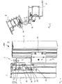
- the hinge arrangement denoted as a whole by 100 in the drawing, is used to pivot a sash F, of which only a section of a sash profile 1 is shown, on a frame profile 2 of a stationary frame R.
- the frame profiles 1, 2 are designed as hollow profiles.
- the belt arrangement 100 comprises a belt 3, which is designed as a so-called roller belt. It comprises hinge parts 4, 5 which receive a hinge pin 6 defining the hinge axis S.
- the hinge parts 4, 5 are arranged on the outside of the profiles 1, 2 close to their front wall 7, 8, which is located in a common plane V when the sash F is closed (cf. Fig. 3 ).
- the wing 8 can around the hinge pin 6 according to the in Fig. 3 opening side located above in the direction of arrow P, for example in the in Fig. 2 reproduced position can be pivoted.
- the two profiles 1, 2 are designed such that a rebate area 9 remains between them.
- the vertically superimposed hinge parts 4, 5 of the belt 3, of which in Fig. 2 and 3 only the wing hinge part 4 can be seen, have fastening legs 10, 11 on their rear side facing the wing F or the frame R, which engage into the interior of the rebate area 9 through a shadow groove 12 between the profiles 1, 2 (cf. in particular Fig. 3 ).
- the fastening leg 10 is angled inside the rebate area 9 under the rebate part 13 in the direction of the sash profile 1 and ends in a widened area 14, the top side of which facing the sash profile 1 forms a first contact surface 15 of a second hinge part 16.
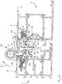
- the contact side of the first band part 17 is pierced by a recess 21 into which a projection 22 extending vertically from the fastening wall 19 protrudes.
- a clamping screw 24 designed as a stud screw is screwed. It is supported with its front end in the screwing-in direction on a surface of the projection 22 that is perpendicular to the fastening wall 19, engaging behind an according to FIG Fig. 3 downward bend 25 of the projection 22.
- Fig. 3 the frictional connection achieved with the help of the clamping screw 24 causes the first hinge part 17 to be fixed to the sash profile 1.
- two pairs of cap screws 26, 27 are also provided, which are designed as self-tapping screws .
- Head screw 26 of the upper pair shown further above penetrates a hole not shown in the drawing perpendicular to the fastening wall 19, its thread being in operative connection with a perforation in the fastening wall 19.
- the head screw 27 underneath is screwed in through a correspondingly aligned bore in the first hinge part 17, likewise not visible in the drawing, at an angle ⁇ to the perpendicular of the fastening wall 19, which in the illustrated embodiment is approximately 45 °.
- the second hinge part 16 is connected to the first hinge part 17 with the aid of fastening screws 28 designed as head screws with machine thread, which are screwed into threaded bores incorporated in the first hinge part 17, which cannot be seen in the drawing.
- the fastening screws 28 penetrate the second hinge part 16 in elongated openings 29.
- a plate-shaped spacer element 31 is inserted between the first contact surface 15 of the second band part 16 and the opposite, first contact surface 30 of the first band part 17.
- the spacer element 31 can be replaced by another with a different thickness to adjust the distance between the wing F and the frame R perpendicular to the hinge axis S, the so-called "horizontal adjustment". Or the number of inserted spacer elements 31 is changed.
- the second hinge part 16 can be displaced relative to the first hinge part 17 in the longitudinal direction of the elongated openings 29 after loosening the fastening screws 28.
- an adjusting screw 32 designed as a stud screw is screwed into the first hinge part 17 in a threaded hole not shown in the drawing.
- the front in screw-in direction, in Fig. 1 The upper end of the adjusting screw 32 forms a second contact surface 33 of the first hinge part, which rests against a second contact surface 34 of the second hinge part 16.
- the first hinge part 17 above the second hinge part 16 has a corresponding design with an adjusting screw 32 and second contact surfaces 33, 34. Due to this measure, it is on the one hand possible to use the sash hinge part 18 without modification for both the right and left hinged sashes, on the other hand, the second hinge part 16 can be additionally fixed with respect to the first hinge part 17 by using the upper one after reaching the desired adjustment position Adjusting screw 32 is tightened.
- the openings 29 are made so wide that there is sufficient play for a relative displacement even perpendicular to their longitudinal extension to the fastening screw 28.
- a projection 41 is provided which can optionally be introduced into one of a plurality of recesses 42 provided in the second hinge part 16.
- Fig. 3 the extreme position of the second hinge part 16 is shown, in which the hinge axis S has the maximum distance in front of the front side 7.
- the hinge part 5 and the frame hinge part 35 comprising the fastening leg 11 it is possible for the hinge part 5 and the frame hinge part 35 comprising the fastening leg 11 to configure the sash hinge part 18 in a corresponding manner.
- the fastening leg is formed in one piece in the frame hinge part 35 of the hinge arrangement 100.
- the attachment to the frame profile 2, which also comprises a projection 36 protruding vertically from the attachment wall 20 and protruding into a recess 37, is carried out in the same way by means of a clamping screw 38 and cap screws 39, 49 as the above-described attachment of the first hinge part 17 of the Sash hinge part 18 on the sash profile 1.
- Tag List : ⁇ /u> ⁇ /b> 100 Band arrangement 31 Spacer element 1 Sash profile 32 Adjusting screw 2 Frame profile 33 second contact surface 3 tape 34 second contact surface 4th Hinge part 35 Frame hinge part 5 Hinge part 36 head Start 6 Hinge pin 37 Recess 7th Front wall 38 Clamping screw 8th Front wall 39 Cap screw 9 Folding area 40 Cap screw 10 Mounting leg 41 head Start 11 Mounting leg 42 Hopper 12 Shadow groove F. wing 13th Folded part R. frame 14th Area V level 15th first contact surface S.
Landscapes
- Engineering & Computer Science (AREA)
- Mechanical Engineering (AREA)
- Hinges (AREA)
Priority Applications (3)
| Application Number | Priority Date | Filing Date | Title |
|---|---|---|---|
| PL14190122T PL2837762T3 (pl) | 2009-11-23 | 2009-11-23 | Układ zawiasów do drzwi, okien i tym podobnych |
| EP14190122.3A EP2837762B1 (de) | 2009-11-23 | 2009-11-23 | Bandanordnung für Türen, Fenster oder dergleichen |
| ES14190122T ES2823982T3 (es) | 2009-11-23 | 2009-11-23 | Sistema de bisagra para puertas, ventanas y similares |
Applications Claiming Priority (3)
| Application Number | Priority Date | Filing Date | Title |
|---|---|---|---|
| EP09763914.0A EP2504510B1 (de) | 2009-11-23 | 2009-11-23 | Bandanordnung für türen, fenster oder dergleichen |
| EP14190122.3A EP2837762B1 (de) | 2009-11-23 | 2009-11-23 | Bandanordnung für Türen, Fenster oder dergleichen |
| PCT/EP2009/065637 WO2011060835A1 (de) | 2009-11-23 | 2009-11-23 | Bandanordnung für türen, fenster oder dergleichen |
Related Parent Applications (2)
| Application Number | Title | Priority Date | Filing Date |
|---|---|---|---|
| EP09763914.0A Division EP2504510B1 (de) | 2009-11-23 | 2009-11-23 | Bandanordnung für türen, fenster oder dergleichen |
| EP09763914.0A Division-Into EP2504510B1 (de) | 2009-11-23 | 2009-11-23 | Bandanordnung für türen, fenster oder dergleichen |
Publications (2)
| Publication Number | Publication Date |
|---|---|
| EP2837762A1 EP2837762A1 (de) | 2015-02-18 |
| EP2837762B1 true EP2837762B1 (de) | 2020-08-19 |
Family
ID=42477652
Family Applications (2)
| Application Number | Title | Priority Date | Filing Date |
|---|---|---|---|
| EP14190122.3A Active EP2837762B1 (de) | 2009-11-23 | 2009-11-23 | Bandanordnung für Türen, Fenster oder dergleichen |
| EP09763914.0A Active EP2504510B1 (de) | 2009-11-23 | 2009-11-23 | Bandanordnung für türen, fenster oder dergleichen |
Family Applications After (1)
| Application Number | Title | Priority Date | Filing Date |
|---|---|---|---|
| EP09763914.0A Active EP2504510B1 (de) | 2009-11-23 | 2009-11-23 | Bandanordnung für türen, fenster oder dergleichen |
Country Status (5)
| Country | Link |
|---|---|
| EP (2) | EP2837762B1 (pl) |
| CN (1) | CN102648325B (pl) |
| ES (2) | ES2811231T3 (pl) |
| PL (2) | PL2504510T3 (pl) |
| WO (1) | WO2011060835A1 (pl) |
Families Citing this family (9)
| Publication number | Priority date | Publication date | Assignee | Title |
|---|---|---|---|---|
| CN103967368B (zh) * | 2014-04-02 | 2015-12-02 | 宁波市维特建筑五金有限公司 | 一种门窗铰链 |
| DE202015100200U1 (de) | 2015-01-19 | 2016-04-20 | Dr. Hahn Gmbh & Co. Kg | Bandlappenanordnung eines Bandes |
| WO2018113906A1 (de) * | 2016-12-19 | 2018-06-28 | Dr. Hahn Gmbh & Co. Kg | Befestigungssystem |
| CN107339039A (zh) * | 2017-07-20 | 2017-11-10 | 亚萨合莱国强(山东)五金科技有限公司 | 一种耐火框扇连接装置 |
| CN109386199A (zh) * | 2017-08-10 | 2019-02-26 | 珠海广通汽车有限公司 | 客车侧舱铰链装置 |
| BE1026576B1 (nl) * | 2018-08-28 | 2020-03-30 | PARYS Emmanuel Diederich Camille VAN | Verdektliggend scharnier voor een deur of raam en deur of raam daarmee uitgerust en werkwijze voor het monteren van een vleugel in een vast kader van een raam of deur. |
| DE102018127282B4 (de) * | 2018-10-31 | 2020-06-18 | Dr. Hahn Gmbh & Co. Kg | Baugruppe eines Bandes zur um eine Scharnierachse scharniergelenkigen Verbindung eines Flügels mit einem Rahmen sowie Band mit dieser Baugruppe |
| DE102018130350B3 (de) * | 2018-11-29 | 2020-03-26 | Dr. Hahn Gmbh & Co. Kg | Bandlappen und Band zur um eine Scharnierachse scharniergelenkigen Verbindung eines Flügels mit einem Rahmen |
| PL431117A1 (pl) | 2019-09-11 | 2021-03-22 | WALA Spółka z ograniczoną odpowiedzialnością | Element osłonowy zawiasowego wycięcia regulacyjnego zespołu ramowego oraz zespół ramowy zawierający taki element osłonowy |
Family Cites Families (13)
| Publication number | Priority date | Publication date | Assignee | Title |
|---|---|---|---|---|
| DE1804108U (de) * | 1959-11-05 | 1960-01-14 | Wieland Werke Ag | Tuerkonstruktion aus stahl oder leichtmetall. |
| DE1945028A1 (de) * | 1969-09-05 | 1971-03-11 | Ver Baubeschlag Gretsch Co | Anordnung von Beschlagteilen in Profilrahmen von Fenstern,Tueren od.dgl. |
| DE2335228A1 (de) * | 1973-07-11 | 1975-01-30 | Weidtmann Fa Wilhelm | Beschlagaggregat fuer hohlprofilrahmen von fenstern, tueren od.dgl |
| DE2624278A1 (de) * | 1976-05-29 | 1977-12-08 | Syco Prod Entwicklungs Gmbh | Befestigung von fenster- oder tuerteilen am rahmenprofil |
| BE863778A (nl) * | 1978-02-08 | 1978-05-29 | Internat Extrusion N V | Scharnier en hierbij horende profielen |
| DE9115427U1 (de) * | 1991-12-12 | 1992-03-19 | Breuer & Schmitz, 5650 Solingen | Holzzargen-Scharnierkonstruktion |
| DE19624558C1 (de) * | 1996-06-20 | 1997-07-31 | Bruynzeel Tueren Gmbh | Vorrichtung zur Befestigung von Bandlappen von Scharnieren an Stahlzargen |
| DE29617826U1 (de) * | 1996-10-14 | 1998-02-12 | Dr. Hahn GmbH & Co. KG., 41189 Mönchengladbach | Bandanordnung für Fenster, Türen u.dgl. |
| DE20005202U1 (de) * | 2000-03-18 | 2001-07-26 | Dr. Hahn GmbH & Co. KG, 41189 Mönchengladbach | Bandanordnung für Türen, Fenster u.dgl. |
| DE20100620U1 (de) * | 2001-01-12 | 2002-05-23 | Dr. Hahn GmbH & Co. KG, 41189 Mönchengladbach | Bandanordnung für Türen, Fenster u.dgl. |
| CH696853A5 (de) * | 2003-12-09 | 2007-12-31 | Harald Sitter | Scharnier, insbesondere für Türen. |
| ITBO20050101A1 (it) * | 2005-02-25 | 2006-08-26 | Gsg Int Spa | Cerniera regolabile per infissi pesanti |
| DE102007028218B3 (de) * | 2007-06-20 | 2008-07-03 | Sfs Intec Holding Ag | Tür- oder Fensterscharnier |
-
2009
- 2009-11-23 PL PL09763914T patent/PL2504510T3/pl unknown
- 2009-11-23 EP EP14190122.3A patent/EP2837762B1/de active Active
- 2009-11-23 ES ES09763914T patent/ES2811231T3/es active Active
- 2009-11-23 EP EP09763914.0A patent/EP2504510B1/de active Active
- 2009-11-23 PL PL14190122T patent/PL2837762T3/pl unknown
- 2009-11-23 ES ES14190122T patent/ES2823982T3/es active Active
- 2009-11-23 WO PCT/EP2009/065637 patent/WO2011060835A1/de not_active Ceased
- 2009-11-23 CN CN200980162557.2A patent/CN102648325B/zh active Active
Non-Patent Citations (1)
| Title |
|---|
| None * |
Also Published As
| Publication number | Publication date |
|---|---|
| CN102648325B (zh) | 2015-09-30 |
| CN102648325A (zh) | 2012-08-22 |
| ES2823982T3 (es) | 2021-05-11 |
| PL2504510T3 (pl) | 2020-12-28 |
| WO2011060835A1 (de) | 2011-05-26 |
| ES2811231T3 (es) | 2021-03-11 |
| EP2504510A1 (de) | 2012-10-03 |
| EP2837762A1 (de) | 2015-02-18 |
| EP2504510B1 (de) | 2020-07-01 |
| PL2837762T3 (pl) | 2021-03-08 |
Similar Documents
| Publication | Publication Date | Title |
|---|---|---|
| EP2504510B1 (de) | Bandanordnung für türen, fenster oder dergleichen | |
| EP0945577B2 (de) | Verwendung einer Profilschiene zum Abstützen von Fenster- oder Türrahmen | |
| DE4219681C2 (de) | Einstellbares Abhebescharnier | |
| EP2873792B1 (de) | Türband | |
| DE602004002173T2 (de) | Einrichtung für eine höheneinstellbare Halterung eines Tores | |
| EP2345787B1 (de) | Türband für Aluminiumtüren | |
| EP2345786B1 (de) | Türband für Aluminiumtüren | |
| DE102014119021B4 (de) | Anordnung zum Befestigen eines Pfostens aus Kunststoff an einer Rahmenleiste eines Fensters oder einer Türe mittels eines Pfostenverbinders | |
| EP2935742A1 (de) | Türsystem | |
| EP1439269B1 (de) | Verbinder für die Befestigung von Montageprofilen der Sanitärtechnik sowie Traggestell mit einem solchen Verbinder | |
| EP3118404B1 (de) | Rollenband, insbesondere für kunststofftüren und kunststofffenster | |
| DE60010806T2 (de) | Verdeckter Öffnungsbeschlag für Drehflügeltür oder -Fenster | |
| DE29904129U1 (de) | Verschwindscharnier | |
| EP2369114B1 (de) | Ausgleichselement für eine Laufschiene sowie ein Verfahren zur Montage des Ausgleichselements | |
| EP1659246A1 (de) | Scharnierbeschlag für Fensterläden | |
| DE102007025857A1 (de) | Gelenkband für Türen oder Fenster | |
| EP0006439B2 (de) | Vorrichtung zur Stossstellenüberlappung an Stulpschienen | |
| EP0750714A1 (de) | Türband | |
| EP1001123B1 (de) | Tür- oder Fensterband | |
| EP0789123B1 (de) | Bandanordnung für Türen, Fenster und dergleichen | |
| DE20001477U1 (de) | Treibstangenbeschlag | |
| EP0770753A1 (de) | Flügel-Eckband für das Ecklager eines Drehkippfensters, einer Tür od. dgl. | |
| DE10153917A1 (de) | Aulagerelement | |
| DE9400022U1 (de) | Sicherheitseinrichtung für Türen, Fenster u.dgl. | |
| DE20112236U1 (de) | Duschabtrennung |
Legal Events
| Date | Code | Title | Description |
|---|---|---|---|
| 17P | Request for examination filed |
Effective date: 20141023 |
|
| AC | Divisional application: reference to earlier application |
Ref document number: 2504510 Country of ref document: EP Kind code of ref document: P |
|
| AK | Designated contracting states |
Kind code of ref document: A1 Designated state(s): AT BE BG CH CY CZ DE DK EE ES FI FR GB GR HR HU IE IS IT LI LT LU LV MC MK MT NL NO PL PT RO SE SI SK SM TR |
|
| PUAI | Public reference made under article 153(3) epc to a published international application that has entered the european phase |
Free format text: ORIGINAL CODE: 0009012 |
|
| R17P | Request for examination filed (corrected) |
Effective date: 20150804 |
|
| RBV | Designated contracting states (corrected) |
Designated state(s): AT BE BG CH CY CZ DE DK EE ES FI FR GB GR HR HU IE IS IT LI LT LU LV MC MK MT NL NO PL PT RO SE SI SK SM TR |
|
| STAA | Information on the status of an ep patent application or granted ep patent |
Free format text: STATUS: EXAMINATION IS IN PROGRESS |
|
| 17Q | First examination report despatched |
Effective date: 20161216 |
|
| GRAP | Despatch of communication of intention to grant a patent |
Free format text: ORIGINAL CODE: EPIDOSNIGR1 |
|
| STAA | Information on the status of an ep patent application or granted ep patent |
Free format text: STATUS: GRANT OF PATENT IS INTENDED |
|
| INTG | Intention to grant announced |
Effective date: 20200331 |
|
| GRAS | Grant fee paid |
Free format text: ORIGINAL CODE: EPIDOSNIGR3 |
|
| GRAA | (expected) grant |
Free format text: ORIGINAL CODE: 0009210 |
|
| STAA | Information on the status of an ep patent application or granted ep patent |
Free format text: STATUS: THE PATENT HAS BEEN GRANTED |
|
| AC | Divisional application: reference to earlier application |
Ref document number: 2504510 Country of ref document: EP Kind code of ref document: P |
|
| AK | Designated contracting states |
Kind code of ref document: B1 Designated state(s): AT BE BG CH CY CZ DE DK EE ES FI FR GB GR HR HU IE IS IT LI LT LU LV MC MK MT NL NO PL PT RO SE SI SK SM TR |
|
| REG | Reference to a national code |
Ref country code: CH Ref legal event code: EP |
|
| REG | Reference to a national code |
Ref country code: DE Ref legal event code: R096 Ref document number: 502009016261 Country of ref document: DE |
|
| REG | Reference to a national code |
Ref country code: AT Ref legal event code: REF Ref document number: 1304114 Country of ref document: AT Kind code of ref document: T Effective date: 20200915 |
|
| REG | Reference to a national code |
Ref country code: IE Ref legal event code: FG4D Free format text: LANGUAGE OF EP DOCUMENT: GERMAN |
|
| REG | Reference to a national code |
Ref country code: SE Ref legal event code: TRGR |
|
| REG | Reference to a national code |
Ref country code: LT Ref legal event code: MG4D |
|
| REG | Reference to a national code |
Ref country code: NL Ref legal event code: MP Effective date: 20200819 |
|
| PG25 | Lapsed in a contracting state [announced via postgrant information from national office to epo] |
Ref country code: LT Free format text: LAPSE BECAUSE OF FAILURE TO SUBMIT A TRANSLATION OF THE DESCRIPTION OR TO PAY THE FEE WITHIN THE PRESCRIBED TIME-LIMIT Effective date: 20200819 Ref country code: GR Free format text: LAPSE BECAUSE OF FAILURE TO SUBMIT A TRANSLATION OF THE DESCRIPTION OR TO PAY THE FEE WITHIN THE PRESCRIBED TIME-LIMIT Effective date: 20201120 Ref country code: HR Free format text: LAPSE BECAUSE OF FAILURE TO SUBMIT A TRANSLATION OF THE DESCRIPTION OR TO PAY THE FEE WITHIN THE PRESCRIBED TIME-LIMIT Effective date: 20200819 Ref country code: PT Free format text: LAPSE BECAUSE OF FAILURE TO SUBMIT A TRANSLATION OF THE DESCRIPTION OR TO PAY THE FEE WITHIN THE PRESCRIBED TIME-LIMIT Effective date: 20201221 Ref country code: BG Free format text: LAPSE BECAUSE OF FAILURE TO SUBMIT A TRANSLATION OF THE DESCRIPTION OR TO PAY THE FEE WITHIN THE PRESCRIBED TIME-LIMIT Effective date: 20201119 Ref country code: NO Free format text: LAPSE BECAUSE OF FAILURE TO SUBMIT A TRANSLATION OF THE DESCRIPTION OR TO PAY THE FEE WITHIN THE PRESCRIBED TIME-LIMIT Effective date: 20201119 Ref country code: FI Free format text: LAPSE BECAUSE OF FAILURE TO SUBMIT A TRANSLATION OF THE DESCRIPTION OR TO PAY THE FEE WITHIN THE PRESCRIBED TIME-LIMIT Effective date: 20200819 |
|
| PG25 | Lapsed in a contracting state [announced via postgrant information from national office to epo] |
Ref country code: LV Free format text: LAPSE BECAUSE OF FAILURE TO SUBMIT A TRANSLATION OF THE DESCRIPTION OR TO PAY THE FEE WITHIN THE PRESCRIBED TIME-LIMIT Effective date: 20200819 Ref country code: NL Free format text: LAPSE BECAUSE OF FAILURE TO SUBMIT A TRANSLATION OF THE DESCRIPTION OR TO PAY THE FEE WITHIN THE PRESCRIBED TIME-LIMIT Effective date: 20200819 Ref country code: IS Free format text: LAPSE BECAUSE OF FAILURE TO SUBMIT A TRANSLATION OF THE DESCRIPTION OR TO PAY THE FEE WITHIN THE PRESCRIBED TIME-LIMIT Effective date: 20201219 |
|
| PG25 | Lapsed in a contracting state [announced via postgrant information from national office to epo] |
Ref country code: EE Free format text: LAPSE BECAUSE OF FAILURE TO SUBMIT A TRANSLATION OF THE DESCRIPTION OR TO PAY THE FEE WITHIN THE PRESCRIBED TIME-LIMIT Effective date: 20200819 Ref country code: CZ Free format text: LAPSE BECAUSE OF FAILURE TO SUBMIT A TRANSLATION OF THE DESCRIPTION OR TO PAY THE FEE WITHIN THE PRESCRIBED TIME-LIMIT Effective date: 20200819 Ref country code: DK Free format text: LAPSE BECAUSE OF FAILURE TO SUBMIT A TRANSLATION OF THE DESCRIPTION OR TO PAY THE FEE WITHIN THE PRESCRIBED TIME-LIMIT Effective date: 20200819 Ref country code: RO Free format text: LAPSE BECAUSE OF FAILURE TO SUBMIT A TRANSLATION OF THE DESCRIPTION OR TO PAY THE FEE WITHIN THE PRESCRIBED TIME-LIMIT Effective date: 20200819 Ref country code: SM Free format text: LAPSE BECAUSE OF FAILURE TO SUBMIT A TRANSLATION OF THE DESCRIPTION OR TO PAY THE FEE WITHIN THE PRESCRIBED TIME-LIMIT Effective date: 20200819 |
|
| REG | Reference to a national code |
Ref country code: ES Ref legal event code: FG2A Ref document number: 2823982 Country of ref document: ES Kind code of ref document: T3 Effective date: 20210511 |
|
| REG | Reference to a national code |
Ref country code: DE Ref legal event code: R097 Ref document number: 502009016261 Country of ref document: DE |
|
| PLBE | No opposition filed within time limit |
Free format text: ORIGINAL CODE: 0009261 |
|
| STAA | Information on the status of an ep patent application or granted ep patent |
Free format text: STATUS: NO OPPOSITION FILED WITHIN TIME LIMIT |
|
| PG25 | Lapsed in a contracting state [announced via postgrant information from national office to epo] |
Ref country code: MC Free format text: LAPSE BECAUSE OF FAILURE TO SUBMIT A TRANSLATION OF THE DESCRIPTION OR TO PAY THE FEE WITHIN THE PRESCRIBED TIME-LIMIT Effective date: 20200819 Ref country code: SK Free format text: LAPSE BECAUSE OF FAILURE TO SUBMIT A TRANSLATION OF THE DESCRIPTION OR TO PAY THE FEE WITHIN THE PRESCRIBED TIME-LIMIT Effective date: 20200819 |
|
| REG | Reference to a national code |
Ref country code: CH Ref legal event code: PL |
|
| 26N | No opposition filed |
Effective date: 20210520 |
|
| GBPC | Gb: european patent ceased through non-payment of renewal fee |
Effective date: 20201123 |
|
| PG25 | Lapsed in a contracting state [announced via postgrant information from national office to epo] |
Ref country code: LU Free format text: LAPSE BECAUSE OF NON-PAYMENT OF DUE FEES Effective date: 20201123 |
|
| PG25 | Lapsed in a contracting state [announced via postgrant information from national office to epo] |
Ref country code: CH Free format text: LAPSE BECAUSE OF NON-PAYMENT OF DUE FEES Effective date: 20201130 Ref country code: LI Free format text: LAPSE BECAUSE OF NON-PAYMENT OF DUE FEES Effective date: 20201130 Ref country code: SI Free format text: LAPSE BECAUSE OF FAILURE TO SUBMIT A TRANSLATION OF THE DESCRIPTION OR TO PAY THE FEE WITHIN THE PRESCRIBED TIME-LIMIT Effective date: 20200819 |
|
| PG25 | Lapsed in a contracting state [announced via postgrant information from national office to epo] |
Ref country code: IE Free format text: LAPSE BECAUSE OF NON-PAYMENT OF DUE FEES Effective date: 20201123 |
|
| PG25 | Lapsed in a contracting state [announced via postgrant information from national office to epo] |
Ref country code: GB Free format text: LAPSE BECAUSE OF NON-PAYMENT OF DUE FEES Effective date: 20201123 |
|
| REG | Reference to a national code |
Ref country code: AT Ref legal event code: MM01 Ref document number: 1304114 Country of ref document: AT Kind code of ref document: T Effective date: 20201123 |
|
| PG25 | Lapsed in a contracting state [announced via postgrant information from national office to epo] |
Ref country code: AT Free format text: LAPSE BECAUSE OF NON-PAYMENT OF DUE FEES Effective date: 20201123 |
|
| PGFP | Annual fee paid to national office [announced via postgrant information from national office to epo] |
Ref country code: SE Payment date: 20211012 Year of fee payment: 13 |
|
| PG25 | Lapsed in a contracting state [announced via postgrant information from national office to epo] |
Ref country code: IS Free format text: LAPSE BECAUSE OF FAILURE TO SUBMIT A TRANSLATION OF THE DESCRIPTION OR TO PAY THE FEE WITHIN THE PRESCRIBED TIME-LIMIT Effective date: 20201219 Ref country code: TR Free format text: LAPSE BECAUSE OF FAILURE TO SUBMIT A TRANSLATION OF THE DESCRIPTION OR TO PAY THE FEE WITHIN THE PRESCRIBED TIME-LIMIT Effective date: 20200819 Ref country code: MT Free format text: LAPSE BECAUSE OF FAILURE TO SUBMIT A TRANSLATION OF THE DESCRIPTION OR TO PAY THE FEE WITHIN THE PRESCRIBED TIME-LIMIT Effective date: 20200819 Ref country code: CY Free format text: LAPSE BECAUSE OF FAILURE TO SUBMIT A TRANSLATION OF THE DESCRIPTION OR TO PAY THE FEE WITHIN THE PRESCRIBED TIME-LIMIT Effective date: 20200819 |
|
| PG25 | Lapsed in a contracting state [announced via postgrant information from national office to epo] |
Ref country code: MK Free format text: LAPSE BECAUSE OF FAILURE TO SUBMIT A TRANSLATION OF THE DESCRIPTION OR TO PAY THE FEE WITHIN THE PRESCRIBED TIME-LIMIT Effective date: 20200819 |
|
| REG | Reference to a national code |
Ref country code: DE Ref legal event code: R082 Ref document number: 502009016261 Country of ref document: DE Representative=s name: PATENTANWAELTE KLUIN DEBELIUS WEBER PARTG MBB, DE |
|
| PGFP | Annual fee paid to national office [announced via postgrant information from national office to epo] |
Ref country code: ES Payment date: 20221208 Year of fee payment: 14 |
|
| P01 | Opt-out of the competence of the unified patent court (upc) registered |
Effective date: 20230523 |
|
| REG | Reference to a national code |
Ref country code: SE Ref legal event code: EUG |
|
| PG25 | Lapsed in a contracting state [announced via postgrant information from national office to epo] |
Ref country code: SE Free format text: LAPSE BECAUSE OF NON-PAYMENT OF DUE FEES Effective date: 20221124 |
|
| REG | Reference to a national code |
Ref country code: ES Ref legal event code: FD2A Effective date: 20250107 |
|
| PG25 | Lapsed in a contracting state [announced via postgrant information from national office to epo] |
Ref country code: ES Free format text: LAPSE BECAUSE OF NON-PAYMENT OF DUE FEES Effective date: 20231124 |
|
| PG25 | Lapsed in a contracting state [announced via postgrant information from national office to epo] |
Ref country code: ES Free format text: LAPSE BECAUSE OF NON-PAYMENT OF DUE FEES Effective date: 20231124 |
|
| PGFP | Annual fee paid to national office [announced via postgrant information from national office to epo] |
Ref country code: DE Payment date: 20251130 Year of fee payment: 17 |
|
| PGFP | Annual fee paid to national office [announced via postgrant information from national office to epo] |
Ref country code: IT Payment date: 20251128 Year of fee payment: 17 |
|
| PGFP | Annual fee paid to national office [announced via postgrant information from national office to epo] |
Ref country code: FR Payment date: 20251120 Year of fee payment: 17 |
|
| PGFP | Annual fee paid to national office [announced via postgrant information from national office to epo] |
Ref country code: BE Payment date: 20251118 Year of fee payment: 17 |
|
| PGFP | Annual fee paid to national office [announced via postgrant information from national office to epo] |
Ref country code: PL Payment date: 20251107 Year of fee payment: 17 |