EP2836740B1 - Dispositif d'entraînement d'un véhicule et procédé de fonctionnement de ce dernier - Google Patents
Dispositif d'entraînement d'un véhicule et procédé de fonctionnement de ce dernier Download PDFInfo
- Publication number
- EP2836740B1 EP2836740B1 EP13707848.1A EP13707848A EP2836740B1 EP 2836740 B1 EP2836740 B1 EP 2836740B1 EP 13707848 A EP13707848 A EP 13707848A EP 2836740 B1 EP2836740 B1 EP 2836740B1
- Authority
- EP
- European Patent Office
- Prior art keywords
- transmission
- clutch
- gear
- hydrodynamic
- input shaft
- Prior art date
- Legal status (The legal status is an assumption and is not a legal conclusion. Google has not performed a legal analysis and makes no representation as to the accuracy of the status listed.)
- Not-in-force
Links
Images


Classifications
-
- F—MECHANICAL ENGINEERING; LIGHTING; HEATING; WEAPONS; BLASTING
- F16—ENGINEERING ELEMENTS AND UNITS; GENERAL MEASURES FOR PRODUCING AND MAINTAINING EFFECTIVE FUNCTIONING OF MACHINES OR INSTALLATIONS; THERMAL INSULATION IN GENERAL
- F16H—GEARING
- F16H47/00—Combinations of mechanical gearing with fluid clutches or fluid gearing
- F16H47/06—Combinations of mechanical gearing with fluid clutches or fluid gearing the fluid gearing being of the hydrokinetic type
-
- B—PERFORMING OPERATIONS; TRANSPORTING
- B60—VEHICLES IN GENERAL
- B60K—ARRANGEMENT OR MOUNTING OF PROPULSION UNITS OR OF TRANSMISSIONS IN VEHICLES; ARRANGEMENT OR MOUNTING OF PLURAL DIVERSE PRIME-MOVERS IN VEHICLES; AUXILIARY DRIVES FOR VEHICLES; INSTRUMENTATION OR DASHBOARDS FOR VEHICLES; ARRANGEMENTS IN CONNECTION WITH COOLING, AIR INTAKE, GAS EXHAUST OR FUEL SUPPLY OF PROPULSION UNITS IN VEHICLES
- B60K6/00—Arrangement or mounting of plural diverse prime-movers for mutual or common propulsion, e.g. hybrid propulsion systems comprising electric motors and internal combustion engines ; Control systems therefor, i.e. systems controlling two or more prime movers, or controlling one of these prime movers and any of the transmission, drive or drive units Informative references: mechanical gearings with secondary electric drive F16H3/72; arrangements for handling mechanical energy structurally associated with the dynamo-electric machine H02K7/00; machines comprising structurally interrelated motor and generator parts H02K51/00; dynamo-electric machines not otherwise provided for in H02K see H02K99/00
- B60K6/20—Arrangement or mounting of plural diverse prime-movers for mutual or common propulsion, e.g. hybrid propulsion systems comprising electric motors and internal combustion engines ; Control systems therefor, i.e. systems controlling two or more prime movers, or controlling one of these prime movers and any of the transmission, drive or drive units Informative references: mechanical gearings with secondary electric drive F16H3/72; arrangements for handling mechanical energy structurally associated with the dynamo-electric machine H02K7/00; machines comprising structurally interrelated motor and generator parts H02K51/00; dynamo-electric machines not otherwise provided for in H02K see H02K99/00 the prime-movers consisting of electric motors and internal combustion engines, e.g. HEVs
- B60K6/42—Arrangement or mounting of plural diverse prime-movers for mutual or common propulsion, e.g. hybrid propulsion systems comprising electric motors and internal combustion engines ; Control systems therefor, i.e. systems controlling two or more prime movers, or controlling one of these prime movers and any of the transmission, drive or drive units Informative references: mechanical gearings with secondary electric drive F16H3/72; arrangements for handling mechanical energy structurally associated with the dynamo-electric machine H02K7/00; machines comprising structurally interrelated motor and generator parts H02K51/00; dynamo-electric machines not otherwise provided for in H02K see H02K99/00 the prime-movers consisting of electric motors and internal combustion engines, e.g. HEVs characterised by the architecture of the hybrid electric vehicle
- B60K6/48—Parallel type
-
- B—PERFORMING OPERATIONS; TRANSPORTING
- B60—VEHICLES IN GENERAL
- B60T—VEHICLE BRAKE CONTROL SYSTEMS OR PARTS THEREOF; BRAKE CONTROL SYSTEMS OR PARTS THEREOF, IN GENERAL; ARRANGEMENT OF BRAKING ELEMENTS ON VEHICLES IN GENERAL; PORTABLE DEVICES FOR PREVENTING UNWANTED MOVEMENT OF VEHICLES; VEHICLE MODIFICATIONS TO FACILITATE COOLING OF BRAKES
- B60T1/00—Arrangements of braking elements, i.e. of those parts where braking effect occurs specially for vehicles
- B60T1/02—Arrangements of braking elements, i.e. of those parts where braking effect occurs specially for vehicles acting by retarding wheels
- B60T1/06—Arrangements of braking elements, i.e. of those parts where braking effect occurs specially for vehicles acting by retarding wheels acting otherwise than on tread, e.g. employing rim, drum, disc, or transmission or on double wheels
- B60T1/062—Arrangements of braking elements, i.e. of those parts where braking effect occurs specially for vehicles acting by retarding wheels acting otherwise than on tread, e.g. employing rim, drum, disc, or transmission or on double wheels acting on transmission parts
-
- B—PERFORMING OPERATIONS; TRANSPORTING
- B60—VEHICLES IN GENERAL
- B60T—VEHICLE BRAKE CONTROL SYSTEMS OR PARTS THEREOF; BRAKE CONTROL SYSTEMS OR PARTS THEREOF, IN GENERAL; ARRANGEMENT OF BRAKING ELEMENTS ON VEHICLES IN GENERAL; PORTABLE DEVICES FOR PREVENTING UNWANTED MOVEMENT OF VEHICLES; VEHICLE MODIFICATIONS TO FACILITATE COOLING OF BRAKES
- B60T1/00—Arrangements of braking elements, i.e. of those parts where braking effect occurs specially for vehicles
- B60T1/02—Arrangements of braking elements, i.e. of those parts where braking effect occurs specially for vehicles acting by retarding wheels
- B60T1/08—Arrangements of braking elements, i.e. of those parts where braking effect occurs specially for vehicles acting by retarding wheels using fluid or powdered medium
- B60T1/087—Arrangements of braking elements, i.e. of those parts where braking effect occurs specially for vehicles acting by retarding wheels using fluid or powdered medium in hydrodynamic, i.e. non-positive displacement, retarders
-
- B—PERFORMING OPERATIONS; TRANSPORTING
- B60—VEHICLES IN GENERAL
- B60T—VEHICLE BRAKE CONTROL SYSTEMS OR PARTS THEREOF; BRAKE CONTROL SYSTEMS OR PARTS THEREOF, IN GENERAL; ARRANGEMENT OF BRAKING ELEMENTS ON VEHICLES IN GENERAL; PORTABLE DEVICES FOR PREVENTING UNWANTED MOVEMENT OF VEHICLES; VEHICLE MODIFICATIONS TO FACILITATE COOLING OF BRAKES
- B60T10/00—Control or regulation for continuous braking making use of fluid or powdered medium, e.g. for use when descending a long slope
- B60T10/02—Control or regulation for continuous braking making use of fluid or powdered medium, e.g. for use when descending a long slope with hydrodynamic brake
-
- B—PERFORMING OPERATIONS; TRANSPORTING
- B60—VEHICLES IN GENERAL
- B60W—CONJOINT CONTROL OF VEHICLE SUB-UNITS OF DIFFERENT TYPE OR DIFFERENT FUNCTION; CONTROL SYSTEMS SPECIALLY ADAPTED FOR HYBRID VEHICLES; ROAD VEHICLE DRIVE CONTROL SYSTEMS FOR PURPOSES NOT RELATED TO THE CONTROL OF A PARTICULAR SUB-UNIT
- B60W30/00—Purposes of road vehicle drive control systems not related to the control of a particular sub-unit, e.g. of systems using conjoint control of vehicle sub-units, or advanced driver assistance systems for ensuring comfort, stability and safety or drive control systems for propelling or retarding the vehicle
- B60W30/18—Propelling the vehicle
- B60W30/18009—Propelling the vehicle related to particular drive situations
- B60W30/18027—Drive off, accelerating from standstill
-
- F—MECHANICAL ENGINEERING; LIGHTING; HEATING; WEAPONS; BLASTING
- F16—ENGINEERING ELEMENTS AND UNITS; GENERAL MEASURES FOR PRODUCING AND MAINTAINING EFFECTIVE FUNCTIONING OF MACHINES OR INSTALLATIONS; THERMAL INSULATION IN GENERAL
- F16D—COUPLINGS FOR TRANSMITTING ROTATION; CLUTCHES; BRAKES
- F16D57/00—Liquid-resistance brakes; Brakes using the internal friction of fluids or fluid-like media, e.g. powders
- F16D57/04—Liquid-resistance brakes; Brakes using the internal friction of fluids or fluid-like media, e.g. powders with blades causing a directed flow, e.g. Föttinger type
-
- F—MECHANICAL ENGINEERING; LIGHTING; HEATING; WEAPONS; BLASTING
- F16—ENGINEERING ELEMENTS AND UNITS; GENERAL MEASURES FOR PRODUCING AND MAINTAINING EFFECTIVE FUNCTIONING OF MACHINES OR INSTALLATIONS; THERMAL INSULATION IN GENERAL
- F16H—GEARING
- F16H3/00—Toothed gearings for conveying rotary motion with variable gear ratio or for reversing rotary motion
- F16H3/006—Toothed gearings for conveying rotary motion with variable gear ratio or for reversing rotary motion power being selectively transmitted by either one of the parallel flow paths
-
- F—MECHANICAL ENGINEERING; LIGHTING; HEATING; WEAPONS; BLASTING
- F16—ENGINEERING ELEMENTS AND UNITS; GENERAL MEASURES FOR PRODUCING AND MAINTAINING EFFECTIVE FUNCTIONING OF MACHINES OR INSTALLATIONS; THERMAL INSULATION IN GENERAL
- F16H—GEARING
- F16H3/00—Toothed gearings for conveying rotary motion with variable gear ratio or for reversing rotary motion
- F16H3/02—Toothed gearings for conveying rotary motion with variable gear ratio or for reversing rotary motion without gears having orbital motion
- F16H3/08—Toothed gearings for conveying rotary motion with variable gear ratio or for reversing rotary motion without gears having orbital motion exclusively or essentially with continuously meshing gears, that can be disengaged from their shafts
- F16H3/087—Toothed gearings for conveying rotary motion with variable gear ratio or for reversing rotary motion without gears having orbital motion exclusively or essentially with continuously meshing gears, that can be disengaged from their shafts characterised by the disposition of the gears
- F16H3/093—Toothed gearings for conveying rotary motion with variable gear ratio or for reversing rotary motion without gears having orbital motion exclusively or essentially with continuously meshing gears, that can be disengaged from their shafts characterised by the disposition of the gears with two or more countershafts
- F16H3/097—Toothed gearings for conveying rotary motion with variable gear ratio or for reversing rotary motion without gears having orbital motion exclusively or essentially with continuously meshing gears, that can be disengaged from their shafts characterised by the disposition of the gears with two or more countershafts the input and output shafts being aligned on the same axis
-
- F—MECHANICAL ENGINEERING; LIGHTING; HEATING; WEAPONS; BLASTING
- F16—ENGINEERING ELEMENTS AND UNITS; GENERAL MEASURES FOR PRODUCING AND MAINTAINING EFFECTIVE FUNCTIONING OF MACHINES OR INSTALLATIONS; THERMAL INSULATION IN GENERAL
- F16H—GEARING
- F16H61/00—Control functions within control units of change-speed- or reversing-gearings for conveying rotary motion ; Control of exclusively fluid gearing, friction gearing, gearings with endless flexible members or other particular types of gearing
- F16H61/04—Smoothing ratio shift
- F16H61/0403—Synchronisation before shifting
-
- B—PERFORMING OPERATIONS; TRANSPORTING
- B60—VEHICLES IN GENERAL
- B60K—ARRANGEMENT OR MOUNTING OF PROPULSION UNITS OR OF TRANSMISSIONS IN VEHICLES; ARRANGEMENT OR MOUNTING OF PLURAL DIVERSE PRIME-MOVERS IN VEHICLES; AUXILIARY DRIVES FOR VEHICLES; INSTRUMENTATION OR DASHBOARDS FOR VEHICLES; ARRANGEMENTS IN CONNECTION WITH COOLING, AIR INTAKE, GAS EXHAUST OR FUEL SUPPLY OF PROPULSION UNITS IN VEHICLES
- B60K6/00—Arrangement or mounting of plural diverse prime-movers for mutual or common propulsion, e.g. hybrid propulsion systems comprising electric motors and internal combustion engines ; Control systems therefor, i.e. systems controlling two or more prime movers, or controlling one of these prime movers and any of the transmission, drive or drive units Informative references: mechanical gearings with secondary electric drive F16H3/72; arrangements for handling mechanical energy structurally associated with the dynamo-electric machine H02K7/00; machines comprising structurally interrelated motor and generator parts H02K51/00; dynamo-electric machines not otherwise provided for in H02K see H02K99/00
- B60K6/20—Arrangement or mounting of plural diverse prime-movers for mutual or common propulsion, e.g. hybrid propulsion systems comprising electric motors and internal combustion engines ; Control systems therefor, i.e. systems controlling two or more prime movers, or controlling one of these prime movers and any of the transmission, drive or drive units Informative references: mechanical gearings with secondary electric drive F16H3/72; arrangements for handling mechanical energy structurally associated with the dynamo-electric machine H02K7/00; machines comprising structurally interrelated motor and generator parts H02K51/00; dynamo-electric machines not otherwise provided for in H02K see H02K99/00 the prime-movers consisting of electric motors and internal combustion engines, e.g. HEVs
- B60K6/42—Arrangement or mounting of plural diverse prime-movers for mutual or common propulsion, e.g. hybrid propulsion systems comprising electric motors and internal combustion engines ; Control systems therefor, i.e. systems controlling two or more prime movers, or controlling one of these prime movers and any of the transmission, drive or drive units Informative references: mechanical gearings with secondary electric drive F16H3/72; arrangements for handling mechanical energy structurally associated with the dynamo-electric machine H02K7/00; machines comprising structurally interrelated motor and generator parts H02K51/00; dynamo-electric machines not otherwise provided for in H02K see H02K99/00 the prime-movers consisting of electric motors and internal combustion engines, e.g. HEVs characterised by the architecture of the hybrid electric vehicle
- B60K6/48—Parallel type
- B60K2006/4825—Electric machine connected or connectable to gearbox input shaft
-
- F—MECHANICAL ENGINEERING; LIGHTING; HEATING; WEAPONS; BLASTING
- F16—ENGINEERING ELEMENTS AND UNITS; GENERAL MEASURES FOR PRODUCING AND MAINTAINING EFFECTIVE FUNCTIONING OF MACHINES OR INSTALLATIONS; THERMAL INSULATION IN GENERAL
- F16H—GEARING
- F16H61/00—Control functions within control units of change-speed- or reversing-gearings for conveying rotary motion ; Control of exclusively fluid gearing, friction gearing, gearings with endless flexible members or other particular types of gearing
- F16H61/04—Smoothing ratio shift
- F16H61/0403—Synchronisation before shifting
- F16H2061/0414—Synchronisation before shifting by retarder control
-
- F—MECHANICAL ENGINEERING; LIGHTING; HEATING; WEAPONS; BLASTING
- F16—ENGINEERING ELEMENTS AND UNITS; GENERAL MEASURES FOR PRODUCING AND MAINTAINING EFFECTIVE FUNCTIONING OF MACHINES OR INSTALLATIONS; THERMAL INSULATION IN GENERAL
- F16H—GEARING
- F16H2200/00—Transmissions for multiple ratios
- F16H2200/003—Transmissions for multiple ratios characterised by the number of forward speeds
- F16H2200/0056—Transmissions for multiple ratios characterised by the number of forward speeds the gear ratios comprising seven forward speeds
-
- F—MECHANICAL ENGINEERING; LIGHTING; HEATING; WEAPONS; BLASTING
- F16—ENGINEERING ELEMENTS AND UNITS; GENERAL MEASURES FOR PRODUCING AND MAINTAINING EFFECTIVE FUNCTIONING OF MACHINES OR INSTALLATIONS; THERMAL INSULATION IN GENERAL
- F16H—GEARING
- F16H2200/00—Transmissions for multiple ratios
- F16H2200/0082—Transmissions for multiple ratios characterised by the number of reverse speeds
-
- F—MECHANICAL ENGINEERING; LIGHTING; HEATING; WEAPONS; BLASTING
- F16—ENGINEERING ELEMENTS AND UNITS; GENERAL MEASURES FOR PRODUCING AND MAINTAINING EFFECTIVE FUNCTIONING OF MACHINES OR INSTALLATIONS; THERMAL INSULATION IN GENERAL
- F16H—GEARING
- F16H2312/00—Driving activities
- F16H2312/02—Driving off
-
- Y—GENERAL TAGGING OF NEW TECHNOLOGICAL DEVELOPMENTS; GENERAL TAGGING OF CROSS-SECTIONAL TECHNOLOGIES SPANNING OVER SEVERAL SECTIONS OF THE IPC; TECHNICAL SUBJECTS COVERED BY FORMER USPC CROSS-REFERENCE ART COLLECTIONS [XRACs] AND DIGESTS
- Y02—TECHNOLOGIES OR APPLICATIONS FOR MITIGATION OR ADAPTATION AGAINST CLIMATE CHANGE
- Y02T—CLIMATE CHANGE MITIGATION TECHNOLOGIES RELATED TO TRANSPORTATION
- Y02T10/00—Road transport of goods or passengers
- Y02T10/60—Other road transportation technologies with climate change mitigation effect
- Y02T10/62—Hybrid vehicles
-
- Y—GENERAL TAGGING OF NEW TECHNOLOGICAL DEVELOPMENTS; GENERAL TAGGING OF CROSS-SECTIONAL TECHNOLOGIES SPANNING OVER SEVERAL SECTIONS OF THE IPC; TECHNICAL SUBJECTS COVERED BY FORMER USPC CROSS-REFERENCE ART COLLECTIONS [XRACs] AND DIGESTS
- Y10—TECHNICAL SUBJECTS COVERED BY FORMER USPC
- Y10S—TECHNICAL SUBJECTS COVERED BY FORMER USPC CROSS-REFERENCE ART COLLECTIONS [XRACs] AND DIGESTS
- Y10S903/00—Hybrid electric vehicles, HEVS
- Y10S903/902—Prime movers comprising electrical and internal combustion motors
- Y10S903/903—Prime movers comprising electrical and internal combustion motors having energy storing means, e.g. battery, capacitor
- Y10S903/904—Component specially adapted for hev
- Y10S903/915—Specific drive or transmission adapted for hev
Definitions
- the invention relates to a drive device of a vehicle according to the preamble of patent claim 1, and a method for its operation according to the preamble of claim 9.
- Drive devices of vehicles with manual transmissions, the two partial transmissions or in their operation comparable separate, usually automatically or automatically switchable transmission strands are already known. Certain functions of such a drive are usually associated with only one of the two partial transmissions or representable over this, so that unbalanced loads on the partial transmissions can occur or certain functions are mutually exclusive or only with restrictions available.
- a dual-clutch transmission for example, usually one of two input-side power shift clutches always used as a starting clutch, since the preferred starting gear is located in the respective partial transmission. If the drive is subjected to frequent start-up procedures, such as in the case of a city bus, this can lead to thermal overload with premature wear of the relevant clutch.
- vehicle transmissions which are subject to high loads on their starting and braking devices, such as powershift transmissions for city buses, where frequent, briefly successive start-up and braking occur with a hydrodynamic torque converter as a wear-free starting element and optionally with an additional wear-free permanent braking device to equip a hydrodynamic retarder.
- a hydrodynamic torque converter as a wear-free starting element and optionally with an additional wear-free permanent braking device to equip a hydrodynamic retarder.
- the mechanical energy of a drive shaft is converted with the generation of heat into the kinetic energy of a fluid and back into the mechanical energy of an output shaft.
- a simple fluid coupling with a driving impeller and a driven turbine wheel acts as a continuously variable transmission with an input and output side speed difference.
- an additional stator by a deflection of the flow in the direction of impeller ensures a torque increase in the torque conversion.
- a retarder a fixed paddle wheel, the stator, creates a braking action on the driving wheel, the rotor, thereby causing a braking effect on the drive train.
- starting retarders which combine the functions of a hydrodynamic starting element, such as a fluid coupling or a torque converter, and a hydrodynamic retarder in a structural unit.
- a hydrodynamic coupling is used with a pump and a turbine wheel, wherein the impeller is connected to a drive motor and a friction clutch for bridging the impeller and turbine is connected in parallel, and wherein the turbine via a freewheel with a transmission input a downstream gearbox is connected and can be detected by a turbine brake with respect to a housing.
- the power is transmitted via the hydrodynamic circuit to the transmission input.
- the turbine wheel is braked and the friction clutch is closed.
- a transmission unit is known, with a hydraulic transmission part having a primary blade and a secondary impeller, which together form a fluid-filled working space, and with a separate drive technically behind arranged mechanical transmission part as the actual vehicle transmission.
- the mechanical transmission part may be, for example, a planetary gear with one or more coupled planetary gear sets and multiple forward gears and reverse gears.
- the hydraulic transmission part is operable in two operating states, in a driving state as a hydrodynamic coupling and in a braking state as a hydrodynamic retarder.
- the primary impeller works as impeller
- the secondary impeller as turbine wheel.
- the primary paddle wheel is held stationary and operates as a stator, and the secondary paddle wheel is connected to the gearbox and now works backwards as a rotor due to the opposite flow direction.
- the hydraulic transmission part is associated with a plurality of switching elements, which are effective together with other switching elements of the mechanical transmission part in each case on the paddle wheels and one of the paddle wheels or both paddle wheels with the gearbox, bridge or hold.
- a driving operation is realized in each case by means of a forward gear stage or a reverse gear stage with an open or bridged approach retarder.
- a braking operation is realized in each case by means of a reverse gear with held primary impeller.
- the approach retarder allows a hydrodynamic starting process with an additional Starting ratio and a hydrodynamic braking operation.
- the retarder includes a rotatable rotor blade wheel and a fixed stator blade wheel.
- the rotor is connected to a sun gear of the planetary gear set or connectable and connectable or connected to a planet carrier.
- the planet carrier is connected or connectable to an engine-side drive shaft or a transmission-side output shaft of the planetary gear set. Accordingly, a ring gear is connected to the output shaft or the drive shaft.
- the retarder is designed as a so-called double-flow retarder.
- This has two flow circuits, with two outer axially opposed stators, each with inwardly facing blading, and an axially inner rotor with double-sided blading.
- the rotor can produce in its two possible directions of rotation in each case a sufficiently high braking power.
- a transmission having a main shaft, a first and a second input shaft and a first clutch drivingly coupling the main shaft and the first clutch and a second clutch drivingly coupling the main shaft and the second input shaft.
- the transmission includes either a torque converter selectively driven by the first input shaft, a first gear set for the first gear driven by the torque converter, or a torque converter selectively driven by a first gear set for the first gear, the first one Gear set for the first gear is driven by the input shaft.
- a motor vehicle starting element known in the form of a clutch with a rotationally driven primary side and a hydrodynamically or electrodynamically rotationally driven from the primary side secondary side, comprising a braking device for decelerating and / or stationary holding the secondary side, wherein the braking device is an electric machine, which is a stator and a rotor, which are coupled to each other via an electromagnetic interaction, and wherein the rotor with the secondary side of the controllable clutch is rotatably connected or connectable to delay the secondary side.
- the invention has the object to provide an improved drive device of a vehicle with partial transmissions, which is comfortable and durable, especially with regard to frequent startup and stopping operations. Another object is to provide a method for operating such a drive device.
- the invention is based on the finding that a vehicle transmission in which an input clutch is used both as a load switching means and as a starting means, as usual in dual-clutch transmissions and hybrid transmissions, can be supplemented by an additional hydrodynamic starting element.
- a hydrodynamic starting element which is effective on a gear path with a starting gear, can decouple said power-shift clutch or the electric machine from the function of a starting element. The Lastschaltkuppiung is thus protected while driving against increased wear or flexible use.
- the invention is based on a drive device of a vehicle, with an internal combustion engine and with a transmission which is designed as a multi-stage transmission with two partial transmissions and a separate transmission input shaft, wherein a first transmission input shaft of a first partial transmission, a first clutch via which the first transmission input shaft with the internal combustion engine is drive-connected, and wherein a second transmission input shaft of a second sub-transmission, a second clutch is assigned, via which the second transmission input shaft is drivverbindverbindbar with the internal combustion engine.
- the invention provides that the first transmission input shaft is additionally assigned a starting element, which has at least one hydrodynamic transmission element, which has a first functional wheel and a second functional wheel, which can be filled with fluid working space for generating a hydrodynamic Form transmission torque, so that with the help of the starting element at least one starting function is realized, which is effective on the first partial transmission.
- the invention For operating a drive device of a vehicle, with an internal combustion engine and with a transmission which is designed as a multi-stage transmission with two partial transmissions and a separate transmission input shaft, wherein a first transmission input shaft of a first partial transmission, a first clutch, via which the first transmission input shaft to the internal combustion engine drivverbindverbindbar is, and wherein a second transmission input shaft of a second partial transmission, a second clutch is assigned, via which the second transmission input shaft is drivingly connected to the internal combustion engine, the invention provides that at least one hydrodynamic starting function is performed by means of a starting element, wherein the starting element associated with the first transmission input shaft is and has a hydrodynamic transmission element, which has a first functional wheel and a second Has functional wheel, which form a fluid-filled working space for generating a hydrodynamic transmission torque.
- this drive device has a base transmission with two partial transmissions, in which a hydrodynamic starting element is arranged on the input shaft of one of the two partial transmissions.
- the design of the drive device with two partial transmissions allows the circumvention of the hydrodynamic starting element in a driving operation when using the second sub-transmission, whereby the efficiency and economic efficiency of the drive device over a transmission in which a hydrodynamic starting element is always included in the power path improves.
- the basic transmission consisting of the transmission with the two partial transmissions and the hydrodynamic starting element, can also be combined with a dual-clutch module or, in a variant not claimed, also with a hybrid module.
- the base gear can thus be used as a modular component for a dual-clutch transmission, in which the dual clutch is used as a load switching device for a karkraftunterbrechungspick sequential switching sequence.
- the dual clutch or one of the two powershift clutches is not required as a starting element and thus not overstrained by frequently recurring starting operations. This function fulfills the hydrodynamic starting element, which enables a wear-free starting in a gear of the associated sub-transmission.
- the base gear can be used in a not claimed variant as a modular component for a hybrid drive, in which an electric machine which is assigned to one of the two partial transmission, a switching sequence with electrical traction assistance allows by this electric machine replaces a corresponding power shift clutch.
- the starting function is again fulfilled by the hydrodynamic starting element. This has the advantage that the electric machine is independent of a startup process can be operated as a generator for charging an electrical storage and / or for supplying electrical consumers in the electrical system.
- the starting element is designed according to a first claimed alternative as a starting retarder, with a hydrodynamic transmission element with a first rotatable functional wheel and a second rotatable functional wheel, with a planetary gear with a ring gear, a sun gear and a planet carrier, wherein the planet carrier carries a plurality of planetary gears with the sun gear and the ring gear are in meshing engagement, and with a switching element for fixing one of the two functional wheels, wherein the hydrodynamic transmission element and the planetary gear set are coupled together and together form a structural unit.
- the switching element may be formed as a simple form-locking claw switching element or as a frictional brake.
- a start is carried out by means of such Anfahrretarders by a hydrodynamic transmission torque is established by filling the working space of the Anfahrretarders.
- one of the two Planetenradsatziata ring gear or sun gear is effective as a drive element of the planetary gear, which is driven by the drive motor.
- the other of the two Planetenradsatziata ring gear or sun gear which is rotatably connected to the first functional and is detectable via the switching element on a non-rotatable component is detected at a zero crossing of its speed by closing the switching element.
- the planetary carrier which is rotatably connected to the second functional wheel, is effective as an output element of the planetary gear, which drives the transmission input shaft of the first partial transmission.
- the starting retarder When the working space is filled with fluid or partially filled and the switching element is opened, the starting retarder is effective as a fluid coupling without torque escalation. When the working space is filled with fluid or partially filled and the switching element is closed, the starting retarder is effective as a retarder.
- the shift element can be loaded without load, whereby the associated function wheel is braked.
- the hydrodynamic transmission element is thereby switched over from a fluid coupling position to a retarder position. If the working space is subsequently emptied and the retarder is thus deactivated, the planetary gearset acts as a fixed input gear ratio of the relevant subtransmission.
- a drive torque of the internal combustion engine is lowered accordingly, if after closing the switching element, by at least partially emptying the working space, the hydrodynamic transmission torque is reduced.
- the drive torque of the internal combustion engine is simultaneously lowered in order to obtain a constant or continuously variable transmission input torque at the input shaft of the associated subtransmission.
- the starting retarder is in a retarder position, but it is deactivated.
- a hydrodynamic transmission torque can be built up by filling the working space when the switching element is closed, and thereby determined first functional wheel. As a result, a braking effect on the drive can be generated. By dosing the degree of filling of the working space a dosage of the braking torque is possible.
- the two sub-transmissions form with the Anfahrretarder a base gear, which, in the case of a dual-clutch transmission, a double clutch drive technology upstream or downstream can be.
- the two partial transmissions form a dual-clutch transmission in which two clutches are present, wherein one clutch is assigned to a partial transmission, wherein the two clutches are designed as a double clutch, the drive element are preceded by drive-off, with the input side Combustion engine are drivingly connected.
- a first clutch is rotatably connected via a clutch output shaft to an input element of the planetary gear, while a second clutch is rotatably connected to the second transmission input shaft.
- one of the two planetary gear ring gear or sun gear is rotatably connected to the first functional wheel of the hydrodynamic transmission element and can be fixed via the switching element to a stationary component that the other the two Planetenradsatziata ring gear or sun gear is rotatably connected to an output shaft of a first clutch, that the planetary carrier is rotatably connected on the drive side with the second functional wheel, and the output side of the planet carrier is rotatably connected to the first transmission input shaft.
- This drive allows for open switching element and closed first clutch hydrodynamic starting function on the first partial transmission, wherein the fluid coupling transmits the drive torque of the internal combustion engine without torque increase.
- the starting process ie with the switching element still open, a load switching between the two clutches can already take place in order to achieve the shortest possible switching time for a subsequent switching operation. This has an advantageous effect on the performance of the drive during startup processes with strong acceleration.
- the starting retarder When driving in the gears of the second partial transmission, the starting retarder can be disconnected from the drive by the associated first clutch and the switching element are opened, or by the first clutch is opened and the first part transmission is switched to neutral. As a result, unnecessary drag losses of Anfahrretarders be avoided.
- the second possibility allows that the switching element can remain inserted, so that a synchronization for a renewed insertion is omitted.
- the second partial transmission allows the circuit of a direct gear to the transmission input through the second clutch, bypassing the Anfahrretarders, since this is effective only on the first partial transmission. Consequently, no bridging clutch of the starting retarder is required to produce a direct connection between the engine and transmission, which would produce a block circulation of the planetary gear set.
- a direct gear of the overall transmission can also be represented.
- the direct gear is not affected by drag losses at the approach retarder and therefore has a high efficiency.
- the starting retarder When the switching element is closed and the hydrodynamic transmission element is activated, the starting retarder provides a retarder function.
- the retarder function can be realized by braking the input shaft of the first sub-transmission when a gear is engaged in the first sub-transmission. Another possibility for generating a braking effect is to close both clutches when a gear is engaged in the second sub-transmission and no gear is engaged in the first sub-transmission.
- the two partial transmissions form with the Anfahrretarder a base gear, which, in the unclaimed case of a hybrid transmission, a clutch and an electric machine can be upstream.
- the two partial transmissions form a hybrid transmission, in which a clutch and an electric machine are provided, wherein the electric machine is associated with the first partial transmission, the starting element is upstream, and via a drive shaft with a Input element of the planetary gear set is rotatably connected.
- the clutch is assigned to the second partial transmission, upstream of the starting element and has on the input side a clutch input shaft, which is drive-connected to the internal combustion engine, and the clutch is connected on the output side with the second transmission input shaft rotatably.
- a coupling switching element is present, via which the two transmission input shafts can be coupled to one another.
- the Anfahrretarder can be implemented in the drive by one of the two Planetenradsatziata ring gear or sun gear rotatably connected to the first functional wheel of the hydrodynamic transmission element is and can be fixed via the switching element to a stationary component, the other of the two Planetenradsatziata ring gear or sun gear is rotatably connected to a drive shaft of the electric machine, and the planet carrier Drive side is rotatably connected to the second functional gear and the output side is rotatably connected to the first transmission input shaft.
- this drive device eliminates compared to the dual clutch transmission, a first clutch. Instead, a coupling switching element for coupling the two transmission input shafts is present, so that the internal combustion engine can use the gears of the first partial transmission despite elimination of the first clutch.
- the electric machine serves as a load switching element.
- the start-up function is realized by the start-up retarder.
- This hybrid drive allows in a purely electric motor driven operation, ie when the internal combustion engine, starting by means of the hydrodynamic Anfahrretarders. From a generator mode, a delay-free starting is possible with the electric machine. In addition, a permanent crawl mode with simultaneous generator operation can be displayed. Furthermore, a start of the internal combustion engine upon receipt of the tensile force in the drive train is possible from a pure electric motor driven driving operation, wherein torque or speed fluctuations are damped by the fluid coupling.
- the electric motor is not coupled directly to the transmission input. Therefore, possible vibrations in the drive train, which are caused by the mass of the electric motor, largely avoided.
- the two partial transmissions form a hybrid transmission, in which an electric machine is provided, wherein the electric machine is associated with the first partial transmission, the starting element is drivingly upstream and is non-rotatably connected via a drive shaft with an input element of the planetary gear set.
- the second transmission input shaft associated with the second partial transmission is drive-connected to the internal combustion engine.
- a coupling switching element is provided, by means of which the two transmission input shafts can be coupled together.
- a hydraulic fluid pump is arranged, which is connected to a drive shaft of the electric machine.
- a conventionally separately driven hydraulic fluid pump can be dispensed with, since all start-up processes, that is to say even in purely electric motor-driven driving operation, can be performed via the hydrodynamic fluid coupling.
- the hydrodynamic transmission element has a third functional wheel, which is arranged fixedly between the first functional wheel and the second functional wheel, so that a hydrodynamic torque converter is formed by the hydrodynamic transmission element.
- a torque converter instead of a simple fluid coupling, a torque converter can be used, which causes an increase in torque of the drive torque as in known hydrodynamic torque converters.
- the first and the second functional wheel as impeller or turbine wheel and the third functional wheel as a stator are effective.
- an instantaneous adjustment of the driving unit so the internal combustion engine or possibly the electric machine, as is preferably provided in the simple fluid coupling, at a load transfer between the torque converter and the switching element, which the first functional after the zero crossing at slowing down a starting process, not required.
- the instantaneous adjustment can also in the opposite case, ie the load transition of the closed switching element in the retarder during filling of the working space omitted.
- the starting element is designed as a double-flow starting retarder, with a hydrodynamic transmission element with two first, fixed functional wheels and a second, rotatable functional wheel, which form two working spaces with two hydraulic circuits, wherein in each case a hydraulic circuit in a direction of rotation of the rotary functional wheel is effective.
- This dual-flow starting retarder further comprises a planetary gear set, with a ring gear, a sun gear and a planet carrier, which carries a plurality of planetary gears, wherein the planetary gears with the sun gear and the ring gear are in meshing engagement, and a lock-up clutch for coupling two planetary gear set elements.
- the hydrodynamic transmission element and the planetary gear set are coupled together and together form a structural unit.
- the first two functional wheels are two axially outer stators and the second functional wheel is an inner rotor.
- the two stators face each other axially.
- the rotor is rotatably disposed therebetween and each has a blading on both sides.
- the rotor forms with the two stators each a hydraulic circuit.
- a comparable Anfahrretarder is in itself from the above-mentioned DE 198 178 65 A1 known. It is possible to adapt such a starting retarder to a vehicle transmission with two partial transmissions according to the invention.
- the planetary gearset element connected to the second functional wheel that is to say for example the sun gear
- the sun gear is decelerated during a starting process and at the same time a transmission input torque is built up.
- This process is associated with a Momentüberhöhung.
- the sun gear With the planet carrier and thus with the rotating function wheel, so with Coupled to the rotor of the start retarder.
- a retarder operation can be represented. Since the direction of rotation between the rotor and the stator is reversed, the flow should usefully be switched from the first hydraulic circuit into the second hydraulic circuit.
- a correspondingly aligned blading of the functional wheels is effective when starting and during braking, and therefore a hydrodynamic drive torque or a hydrodynamic braking torque can be achieved at a comparable height.
- the arrangement also allows load switching between the two clutches of the dual-clutch transmission, without the startup must be completed by closing the lock-up clutch. Rather, the starting process can be completed via the load circuit. This allows a smaller and thus cheaper design of the lock-up clutch.
- This arrangement allows, similar to the embodiment of the drive device with a single-flow approach retarder, a hydrodynamic starting in a purely electric motor driven driving operation via the fluid coupling.
- a start-up procedure with a closed lockup clutch, ie a mechanical startup, is also possible.
- a vibration decoupling the electric machine is also given.
- the said standstill derating in the inverter can also be avoided.
- Possible, but not claimed, is also a hybrid arrangement with a double-entry starting retarder with omission of the input-side coupling, since the two transmission input shafts can be decoupled or coupled to one another via a coupling switching element anyway.
- the drive shaft of the internal combustion engine can then be rotatably connected to the input shaft of the second partial transmission.
- This arrangement also allows a delay-free starting from a generator operation out, as well as a permanent crawl with simultaneous generator operation.
- a corresponding method is per se in the already mentioned, not previously published DE 10 2011 089 467 A1 known.
- a method for carrying out a load circuit in internal combustion engine drive by means of assistance of the electric machine can in turn be derived in this gear arrangement from a method that in the not previously published DE 10 2010 030 569 A1 the applicant is described.
- a dual clutch is upstream of the Anfahrretarder drive technology.
- the Anfahrretarder forms with the consisting of two partial transmissions vehicle transmission functionally a basic transmission, which is preceded by either a dual clutch module or a hybrid module in terms of drive technology.
- the planetary gear set of the starting retarder represents an input ratio of the relevant first partial transmission.
- the two partial transmissions form a dual-clutch transmission, in which two clutches are provided, wherein in each case a clutch is associated with a partial transmission, wherein the two clutches are designed as single clutches, the starting element are downstream drive technology and the input side, respectively, a separate Have coupling input shaft, wherein a first clutch is associated with the first partial transmission and the input side is rotatably connected via its clutch input shaft with an element of the planetary gear and the output side is rotatably connected to the first transmission input shaft, and wherein a second clutch is associated with the second partial transmission and the input side via its clutch input shaft is drivingly connected to the internal combustion engine and the output side is rotatably connected to the second transmission input shaft.
- one of the two Planetenradsatz emulate ring gear or sun gear is rotatably connected to the first functional wheel of the hydrodynamic transmission element and fixed via the switching element to a stationary component
- the other of the two Planetenradsatz emulate ring gear or Sun gear is drivingly connected to the internal combustion engine and rotatably connected to a clutch input shaft of a second clutch
- the planetary carrier is drivingly connected to the second functional gear rotatably and the output side is rotatably connected to a clutch input shaft of a first clutch.
- the two partial transmissions themselves may be formed in all the embodiments mentioned as a countershaft transmission, wherein the two transmission input shafts are arranged coaxially to each other, wherein a common transmission output shaft is arranged coaxially behind the transmission input shafts, wherein the first part of the transmission associated first transmission input shaft is formed as an outer hollow shaft, in which the second transmission gearbox associated second transmission input shaft is arranged and emerges from the transmission side, wherein the partial transmissions each one of two coaxial superimposed countershafts is assigned, which is drivingly connected to the respective transmission input shaft via a respective gear plane with two gear teeth in meshing engagement, said the sub-transmission include further gear planes, in each of which toothed wheels are arranged in toothed engagement, which are designed as idler gears or fixed wheels and mi t each one of the shafts rotatably connected or rotatably connected via switching devices with one of the shafts, so that the first part transmission is associated with a gear group with odd gears with at least one starting gear and at least one reverse gear,
- This transmission structure is particularly well suited for cooperation with a hydrodynamic starting element, which is effective on one of the two partial transmissions.
- a starting gear is arranged in that part of the transmission, which is associated with the hydrodynamic starting element.
- a reverse gear is also arranged in this sub-transmission to perform both forward and backward frequent starting hydrodynamic and therefore wear-free.
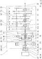
- Fig. 1 shows a drive device of a vehicle with a dual-clutch transmission 1, which has a multi-stage automatic transmission SG with two partial transmissions TG1, TG2, a starting retarder AR, a dual clutch DK with two friction clutches K1, K2, a vibration damper TD and an internal combustion engine VM.
- the manual transmission SG is formed in countershaft design and comprises a total of seven forward gears G1, G2, G3, G4, G5, G6, G7 and a reverse gear RG, which are switchable via four double-sided switching packets S1, S2, S3, S4. Since the construction of a countershaft transmission known per se and the operation of the individual designed as idler gears and fixed gears gears such a transmission for the invention is irrelevant, is omitted to simplify an explicit designation of the individual gears.
- the first partial transmission TG1 provides a gear group with the odd gears G1, G3, G5 G7 and the reverse gear RG.
- the second partial transmission TG2 provides a gear group with the even gears G2, G4, G6.
- the double clutch DK is basically a zugkraftunterbrechungsbuild sequential shift sequence feasible, with one gear is active in one of the two subtransmission TG1, TG2 and in the other subtransmission TG1, TG2 a subsequent gear is selected.
- the gear change takes place in a known manner by intersecting opening and closing of the two clutches K1, K2.
- the two partial transmissions TG1, TG2 each have a separate transmission input shaft GE 1, GE2 and a common transmission output shaft GA.
- the two transmission input shafts GE1, GE2 are arranged coaxially with each other, wherein a first transmission input shaft GE1, which is associated with the first partial transmission TG1, is formed as an outer hollow shaft, in which the second transmission input shaft GE2, which is associated with the second partial transmission TG2, is arranged as an inner shaft, and emerges from this transmission side.
- the forward gears G1, G2, G3, G4, G5, G6, G7 are each arranged in a wheel plane with two gears meshing with each other.
- the reverse gear RG also has a direction of rotation reversal.
- the gearwheels designed as idler gears are arranged on the transmission output shaft GA and can be connected in a rotationally fixed manner to the latter via the respective switching device S1, S2, S3, S4.
- the gear wheels of the two partial transmissions TG1, TG2 designed as fixed gears are located in each case on a countershaft VW1, VW2.
- the two countershafts VW1, VW2 are arranged coaxially with one another, wherein the short second countershaft VW2 is assigned to the second partial transmission TG2 and is arranged as a hollow shaft over the inner first countershaft VW1, which is assigned to the first partial transmission TG1, and emerges from the hollow shaft on both sides.
- the transmission input shaft GE1 of the first partial transmission TG1 is drive-connected to the associated first countershaft VW1 via an input constant EK with two toothed gears in mesh.
- the transmission input shaft GE 2 of the second subtransmission is drive-connected to the associated second countershaft VW2 via the first gear plane of the second subtransmission TG2.
- the transmission input shaft GE 2 of the second partial transmission TG2 is directly connectable to the transmission output shaft GA. Consequently, the sixth gear, which, as in Fig. 1 can be seen, the first gear plane of the second subtransmission TG2 is assigned, designed as a direct gear.
- the second partial transmission TG2 thus allows a direct gear bypassing the Anfahrretarders AR, ie without torque losses by meshing of the planetary gearset PS and without drag torque losses through the fluid coupling HK.
- the two clutches K1, K2 are combined in a double clutch DK.
- the clutch input sides are drive-connected via a common clutch basket and via a common clutch input shaft K_AN to a drive shaft AN_VM of an internal combustion engine VM.
- For vibration damping is disposed between the double clutch DK and the internal combustion engine VM a vibration damper TD.
- the first clutch K1, which is assigned to the first partial transmission TG1 is connected on the output side via an output shaft K1_AB in a rotationally fixed manner to an input element HR of the starting retarder AR described below.
- the second clutch K2, which is assigned to the second partial transmission TG2 is connected on the output side directly to the second transmission input shaft GE2 in a torque-proof manner.
- the starting retarder AR is arranged between the double clutch DK and the manual transmission SG and comprises a hydrodynamic transmission element HK and a planetary gearset PS.
- the planetary gearset PS has an outer ring gear HR as an input element, a central sun gear SR and a planet carrier PT, wherein the planet carrier PT a plurality with the ring gear HR and the sun gear SR meshing planetary gears PR leads.
- the hydrodynamic transmission element HK comprises a first functional wheel FR1 and a second functional wheel FR2.
- the two functional wheels FR1, FR2 are formed as paddle wheels, which face each other and are rotatably arranged. They form a not-shown, usually toroidal working space FL, which can be filled via a hydraulic circuit, not shown, with a fluid, such as oil. The loading and unloading of the working space FL with the fluid can be regulated via the hydraulic circuit.
- a switching element B is arranged between the first functional wheel FR1 and a non-rotatably mounted component GH, for example a housing.
- the switching element B is in Fig. 1 However, it can also be designed as a frictional brake and is therefore also referred to below as a brake.
- the planetary gear set PS and the hydrodynamic transmission element HK are coupled together.
- the ring gear HR of the planetary gearset PS is rotatably connected to the first clutch K1.
- the sun gear SR is connected to the first functional wheel FR1 and, together with the functional wheel FR1 through the Switching element B on the housing GH festbremsbar or detectable.
- the planet carrier PT is connected to the first transmission input shaft GE1 and thus to the first part transmission TG1 of the vehicle transmission SG and to the second functional wheel FR2.
- the hydrodynamic transmission element HK is thus connected between the sun gear SR and the planet carrier PT.
- the speed of the sun gear SR decreases towards zero.
- the switching element or the brake B is loaded without load.
- the transmission capability of the fluid coupling HK is lowered by emptying or partial emptying of the working space FL.
- the brake B thus now supports the transmitted torque. Consequently, the torque of the engine VM is increased.
- the torque of the internal combustion engine VM is lowered in order to keep the transmission input torque on the first partial transmission TG1 constant.
- the open brake B can be synchronized as follows. Initially, the second clutch K2 is closed and a gear engaged in the second partial transmission TG2. The first partial transmission TG1 is switched to neutral, the first clutch K1 is opened and the fluid coupling HK empties, that is, except for a small drag torque, which possibly causes the sun gear SR to rotate easily, torque-free. Subsequently, a gear in the first partial transmission TG1 is inserted. The gear must have a suitable long gear ratio, so that the planet carrier PT rotates sufficiently slower than the drive shaft AW of the engine VM. This is necessary so that the sun gear SR can reach zero speed as a result.
- the first clutch K1 is slightly operated in the closing direction to transmit a small torque sufficient to accelerate the ring gear HR.
- the sun gear SR slows down and reaches the speed zero or a speed approximately zero at which the brake B is engaged.
- the first clutch K1 is opened again to complete the synchronization of the brake element B.
- the second partial transmission TG2 allows a driving operation with decoupled Anfahrretarder AR to avoid drag losses.
- the first clutch K1 and the brake B can be opened, the sun gear SR then turns freely with, the fluid coupling HK consequently produces no drag losses.
- a complete decoupling of the Anfahrretarders AR is possible by the first partial transmission TG1 switched to neutral and the first clutch K1 is opened.
- the switching element of the brake B can then remain engaged, so that its renewed synchronization is eliminated.
- the starting retarder AR is a retarder, ie a retarder.
- a braking operation can be carried out by the input shaft GE1 of the first partial transmission TG1 is braked with filled fluid coupling HK, wherein in the partial transmission TG1 a gear is engaged. If no gear is engaged in the first partial transmission TG1 and a gear is engaged in the second partial transmission TG2, a braking operation can be carried out via the closed double clutch DK, that is to say the first clutch K1 closed and the second clutch K2 closed.
- Fig. 2 shows a drive device of an unclaimed vehicle with a hybrid transmission 2 with the capacity for electrical traction assistance and the starting retarder AR.
- a hybrid module EX / X / K2 is provided instead of the double clutch module DK .
- the hybrid module EX / X / K2 comprises an electric machine EM, a clutch K2 and a coupling switching element X.
- a drive shaft AN_EM of the electric machine EM which is connected to the rotor of the electric machine EM, is connected to the input element, ie the ring gear HR of FIG Planetenradsatzes PS rotatably connected.
- the clutch K2 is arranged between the electric machine EM and the internal combustion engine VM.
- the coupling switching element X is arranged between the clutch K2 and the electric machine EM.
- the coupling switching element X allows a switchable direct connection of the two transmission input shafts GE1, GE2 with each other.
- the start of the deactivated combustion engine VM can be done with the receipt of the tensile force in the drive train and with a slip decoupling.
- the vehicle is initially in a purely electric motor driven driving operation.
- the brake B is engaged, in the first partial transmission TG1 a gear is engaged, the clutch K2 is open.
- the coupling switching element X is inserted. It follows a load build-up on the fluid coupling HK as already described, so that the brake B is free of load and can be designed. Since the output torque decreases because of the reduction of the momentary increase by the planetary gearset PS, the drive torque of the electric machine EM can be increased accordingly, as far as available, to compensate. This is followed by the start of the internal combustion engine VM via the clutch K2.
- the fluid coupling HK dampens any fluctuations in the transmission of the starting torque. Subsequently, a synchronization of the brake B under load by a suitable control of the torques of the engine VM, the electric machine EM and possibly the fluid coupling HK done. Finally, a load reduction takes place at the fluid coupling HK, at the same time the moments of the internal combustion engine VM and the electric machine EM are adapted to achieve a desired torque curve at the output.
- the electric machine EM can support load circuits.
- the electric machine EM supports the output torque via the first partial transmission TG1, while an internal combustion engine-driven gear change takes place.
- the gear change can take place in the second partial transmission TG2.
- the internal combustion engine can be coupled via the coupling switching element X to the first partial transmission TG1 and there the gear change take place.
- the necessary synchronization of these circuits if present, via synchronizations on the coupling element X and / or on the switching packets S1, S2 of the second partial transmission TG2 done.
- the respectively relevant switching elements S2, S3, S4 of the first partial transmission TG1 are synchronized by means of the electric machine EM.
- a purely electric motor driven driving load circuits can be done using the flow coupling HK.
- an upshift in a driving operation via the second partial transmission TG2 shown by closing the coupling element X with the clutch K2 open and brake B open, a subsequent gear can be inserted in the first OperagetriebeTG1.
- the fluid coupling HK takes over the load, so that the second subtransmission TG2 is free of load and the gear of the second subtransmission TG2 can be designed.
- the brake B can be synchronized and inserted.
- the upshift it is basically possible to start the engine VM by utilizing the released flywheel energy of the electric machine EM.
- a train downshift is also possible. In addition to this, turn to the already mentioned DE 10 2010 030 569 A1 the applicant and those already mentioned DE 10 2010 061 827 A1 directed.
- Fig. 3 shows a with the dual clutch transmission 1 of Fig. 1 comparable dual-clutch transmission 3 with a starting retarder AR '.
- a hydrodynamic torque converter HD is provided here. This additionally has a third, fixed functional wheel FR3, which causes a hydrodynamic torque increase of the drive torque as a stator.
- Fig. 4 shows an unclaimed hybrid drive 4 with such a torque converter HD.
- the operation is analogous to that at Fig.1 respectively.
- Fig. 2 described functions.
- an instantaneous adjustment of the internal combustion engine VM or of the electric machine EM in a load transition from the hydrodynamic transmission element HD to the brake B and vice versa is not necessary here.
- the Fig. 5 and the Fig. 6 show a further double-clutch transmission 5 or a further unclaimed hybrid transmission 6.
- a double-flow starting retarder AR is arranged The construction and the mode of operation of such a starting retarder are per se from the above-mentioned DE 198 17 865 A1 known. Therefore, the description is limited here to the connection to the dual-clutch transmission 5 and the hybrid transmission. 6
- the double-entry starting retarder AR has a hydrodynamic transmission element HB with two first, fixed functional wheels STa, STb and a second, rotatable functional wheel RT
- the two stators STa, STb are axially opposite each other, between which the rotor RT is arranged , STb form with the rotor RT in each case a working space FLa, FLb or in each case a hydraulic circuit for both possible directions of rotation of the rotor RT
- a planetary gearset PS as in the Anfahrretardern of Fig. 1 and Fig. 3 intended.
- a lock-up clutch UK is provided. This eliminates the brake B.
- the ring gear HR of the planetary gearset PS is connected to the output shaft K1_AB the first clutch K1.
- the sun gear SR is connected to the rotor RT of the hydrodynamic transmission element HB connected.
- the planet carrier PT is the output side connected to the first transmission input shaft GE1.
- the sun gear SR can be coupled to the planet carrier PT via the bridging clutch UK.
- a hydrodynamic starting function can be used when the lock-up clutch UK is open, and a hydrodynamic retarder function can be shown when the lock-up clutch UK is closed.
- the sun gear SR is increasingly braked in a filled working space FLa or FLb, and a transmission input torque is correspondingly built up on the first transmission input shaft GE1. Due to the stationary second functional wheel (rotor RT), torque is increased.
- the sun gear SR can be hydrodynamically braked to almost standstill.
- the starting process can then be completed by closing the lock-up clutch UK, whereby the planetary gearset PS merges into a block circulation. With emptied retarder HB, the retarder position switched by the bridging clutch UK is inactive.
- the lock-up clutch UK can be closed without load when the gear is laid out in the first sub-transmission TG1.
- the lock-up clutch could then be switched as a synchronized clutch, or be designed accordingly.
- the ring gear HR is connected to the drive shaft AN_EM the electric machine EM
- the sun gear SR is connected to the second functional gear of the hydrodynamic transmission element HB, ie with the rotor RT
- the planet carrier PT is the output side connected to the first transmission input shaft GE1
- the sun gear SR connected to the rotor RT can be coupled to the planet carrier PT via the bridging clutch UK, so that a hydrodynamic starting function can be used when the lockup clutch UK is open and a hydrodynamic retarder function can be used when the lockup clutch UK is closed.
- the hybrid transmission 6 allows a hydrodynamic starting in purely electric motor driven driving operation. Also, a mechanical starting process is possible, now instead of the dropped brake B, the lock-up clutch UK is closed.
- the clutch K2 of the second partial transmission TG2 can be open in order to avoid drag losses. From a generator mode can be approached without delay. In a generator mode, a continuous creep mode can be used.
- the internal combustion engine VM can be started with traction power and slip decoupling. Load circuits with electromotive assistance are possible, as well as load circuits in purely electric motor driven driving operation with the help of the lock-up clutch UK are possible.
- Fig. 7 shows a non-claimed hybrid transmission 7, which is largely identical to the hybrid transmission of Fig. 2 is.
- the hydraulic fluid pump P can also be operated during vehicle standstill.
- a separately driven pump may be omitted if necessary.
- the dual-clutch module is arranged upstream of the starting retarder AR, AR ', AR " Fig. 8
- a further drive device with a dual-clutch transmission 8, in which alternatively two single clutches K1 ', K2' between the Anfahrretarder AR and the gearbox SG are arranged.
- this dual clutch transmission 8 with Anfahrretarder and with the Anfahrretarder AR drivably downstream dual clutch DK ', the sun SR of the planetary PS is connected to the first functional FR1 of the hydrodynamic transmission element HK and fixed via the switching element B to the non-rotatable component GH.
- the ring gear HR is drive-connected to the engine VM and connected to a clutch input shaft K2'_AN of the second clutch K2 '.
- the planet carrier PT is on the drive side rotatably connected to the second functional wheel FR2 and the output side connected to a clutch input shaft K1'_AN the first clutch K1 '.
- the operation is as in the dual-clutch transmission 1 of Fig. 1 ,
Landscapes
- Engineering & Computer Science (AREA)
- Mechanical Engineering (AREA)
- General Engineering & Computer Science (AREA)
- Transportation (AREA)
- Physics & Mathematics (AREA)
- Fluid Mechanics (AREA)
- Automation & Control Theory (AREA)
- Chemical & Material Sciences (AREA)
- Combustion & Propulsion (AREA)
- Structure Of Transmissions (AREA)
- Hybrid Electric Vehicles (AREA)
Claims (11)
- Ensemble d'entraînement pour véhicule, l'ensemble présentant
un moteur à combustion interne (VM) et une transmission configurée comme transmission (SG) à plusieurs rapports dotée de deux transmissions partielles, à savoir une première transmission partielle (TG1) et une deuxième transmission partielle (TG2) présentant chacune un arbre d'entrée de transmission séparé, à savoir un premier arbre (GE1) d'entrée de transmission et un deuxième arbre (GE2) d'entrée de transmission,
un premier embrayage (K1, K1') par lequel le premier arbre (GE1) d'entrée de transmission peut être relié à entraînement au moteur à combustion interne (VM) étant associé au premier arbre (GE1) d'entrée de transmission de la première transmission partielle (TG1) et un deuxième embrayage (K2) par lequel le deuxième arbre (GE2) d'entrée de transmission peut être relié à entraînement au moteur à combustion interne (VM) étant associé au deuxième arbre (GE2) d'entrée de transmission de la deuxième transmission partielle (TG2),
caractérisé en ce que
un élément de démarrage (AR, AR', AR'') est de plus associé au premier arbre (GE1) d'entrée de transmission et présente
un jeu (PS) de roues planétaires doté d'une roue creuse (HR), d'une roue solaire (SR) et d'un porte-planétaires (PT), le porte-planétaires (PT) guidant plusieurs roues planétaires (PR) qui s'engrènent sur la roue solaire (SR) et la roue creuse (HR), et
un élément hydrodynamique de transfert (HK, HD, HB) qui présente une première roue fonctionnelle (FR1, STa, STb) et une deuxième roue fonctionnelle (FR2, RT) qui forment un ou deux espaces de travail (FL, FLa, FLb) aptes à être remplis de fluide en vue de former un couple hydrodynamique de transfert de telle sorte qu'au moins une fonction de démarrage puisse être réalisée à l'aide de l'élément de démarrage (AR, AR', AR'') et puisse agir sur la première transmission partielle (TG1),
en ce que l'élément de démarrage (AR) est configuré comme élément retardateur de démarrage avec l'élément hydrodynamique de transfert (HK), les roues fonctionnelles (FR1, FR2) pouvant tourner et le jeu (PS) de roues planétaires ainsi qu'un élément (B) de changement de rapport qui fixe l'une des deux roues fonctionnelles (FR1, FR2),
ou en ce que l'élément de démarrage (AR") est configuré comme élément retardateur de démarrage à deux étages, avec l'élément hydrodynamique de transfert (HB) et deux premières roues fonctionnelles (STa, STb) fixes, avec la deuxième roue fonctionnelle (RT) apte à tourner, qui forme deux espaces de travail (FLa, FLb) présentant deux circuits hydrauliques, chaque circuit hydraulique agissant dans un sens de rotation de la roue fonctionnelle rotative (RT), et avec le jeu (PS) de roues planétaires ainsi qu'un embrayage de pontage (UK) et
en ce que le jeu (PS) de roues planétaires et l'élément hydrodynamique de transfert (HK, HB) sont accouplés l'un à l'autre et forment ensemble un module. - Dispositif d'entraînement selon la revendication 1, caractérisé en ce que les deux transmissions partielles (TG1, TG2) forment une transmission (1) à double embrayage, les deux embrayages (K1, K2) étant configurés comme doubles embrayages (DK) raccordés en amont de l'élément de démarrage (AR) dans le train de transmission, raccordés à entraînement par leur entrée au moteur à combustion interne (VM), le premier embrayage (K1) étant relié par sa sortie à rotation solidaire à un élément d'entrée (HR) du jeu (PS) de roues planétaires par l'intermédiaire d'un arbre (K1_AB) de sortie d'embrayage et le deuxième embrayage (K2) étant relié à rotation solidaire au deuxième arbre (GE2) d'entrée de transmission.
- Dispositif d'entraînement selon la revendication 2, caractérisé en ce que l'un des deux éléments du jeu de roues planétaires que sont la roue creuse (HR) et la roue solaire (SR) est relié à rotation solidaire à la première roue fonctionnelle (FR1) de l'élément hydrodynamique de transfert (HK) et peut être immobilisé par l'intermédiaire de l'élément de commutation (B) sur un composant fixe (GH), l'autre des deux éléments du jeu de roues planétaires que sont la roue creuse (HR) et la roue solaire (SR) étant relié à rotation solidaire à un arbre de sortie (K1_AB) du premier embrayage (K1),
en ce que le porte-planétaires (PT) est relié à rotation solidaire à la deuxième roue fonctionnelle (FR2) du côté de l'entraînement et
en ce que le porte-planétaires (PT) est relié à rotation solidaire au premier arbre (GE1) d'entrée de transmission du côté entraîné, de telle sorte que lorsque l'élément (B) de changement de rapport est ouvert et que le premier embrayage (K1) est fermé s'établisse une fonction hydrodynamique de démarrage et que lorsque l'élément (B) de changement de rapport est fermé s'établisse une fonction hydrodynamique de retardement. - Ensemble d'entraînement selon l'une des revendications 1 à 3, caractérisé en ce que l'élément hydrodynamique de transfert (HD) présente une troisième roue fonctionnelle (FR3) fixe disposée entre la première roue fonctionnelle (FR1) rotative et la deuxième roue fonctionnelle (FR2) rotative, de telle sorte qu'un convertisseur hydrodynamique de couple de rotation soit formé par l'élément hydrodynamique de transfert (HD).
- Dispositif d'entraînement selon la revendication 2, caractérisé en ce que dans le cas d'un élément retardateur de démarrage (AR'') à double étage, l'un des deux éléments du jeu de roues planétaires que sont la roue creuse (HR) et la roue solaire (SR) est relié à rotation solidaire à l'arbre de sortie (K1_AB) d'un premier embrayage (K1), en ce que l'autre des deux éléments du jeu de roues planétaires que sont la roue creuse (HR) et la roue solaire (SR) est relié à rotation solidaire à la deuxième roue fonctionnelle (RT), en ce que le porte-planétaires (PT) est relié à rotation solidaire du côté entraîné au premier arbre (GE1) d'entrée de transmission et en ce que celui des deux éléments du jeu de roues planétaires que sont la roue creuse (HR) et la roue solaire (SR) qui est relié à rotation solidaire à la deuxième roue fonctionnelle (RT) peut être relié à rotation solidaire au porte-planétaires (PT) par l'intermédiaire de l'embrayage de pontage (UK), de telle sorte que lorsque l'embrayage de pontage (UK) est ouvert s'établisse une fonction hydrodynamique de démarrage et que lorsque l'embrayage de pontage (UK) est fermé s'établisse une fonction hydrodynamique de retardement.
- Ensemble d'entraînement selon la revendication 1, caractérisé en ce que les deux transmissions partielles (TG1, TG2) forment une transmission (8) à double embrayage dans laquelle les deux embrayages (K1', K2') sont prévus, les deux embrayages (K1', K2) étant configurés comme embrayages simples raccordés en aval de l'élément de démarrage (AR) dans le train d'entraînement et présentant côté entrée un arbre séparé (K1'_AN, K2'_AN) d'entrée d'embrayage, le premier embrayage (K1') étant relié à rotation solidaire du côté de son entrée à un élément (PT) du jeu (PS) de roues planétaires par l'intermédiaire de son arbre (K1'_AN) d'entrée d'embrayage et étant relié à rotation solidaire du côté de sa sortie au premier arbre (GE1) d'entrée de transmission, le deuxième embrayage (K2) étant relié à entraînement du côté de son entrée au moteur à combustion interne (VM) par l'intermédiaire de son arbre (K2'_AN) d'entrée d'embrayage et étant relié à rotation solidaire au deuxième arbre (GE2) d'entrée de transmission du côté de sa sortie.
- Ensemble d'entraînement selon la revendication 1, caractérisé en ce que dans le cas d'une transmission (8) à double embrayage et élément retardateur de démarrage (AR) ainsi qu'un double embrayage (DK') prévu en aval de l'élément retardateur d'entraînement (AR) dans le train d'entraînement, l'un des deux éléments du jeu de roues planétaires que sont la roue creuse (HR) et la roue solaire (SR) est relié à rotation solidaire à la première roue fonctionnelle (FR1) apte à tourner de l'élément hydrodynamique de transfert (HK) et peut être immobilisé par l'intermédiaire de l'élément (B) de changement de rapport à un composant fixe (GH), en ce que l'autre des deux éléments du jeu de roues planétaires que sont la roue creuse (HR) et la roue solaire (SR) est relié à entraînement au moteur à combustion interne (VM) et est relié à rotation solidaire à un arbre (K2'_AN) d'entrée d'embrayage du deuxième embrayage (K2) et en ce que le porte-planétaires (PT) est relié à rotation solidaire du côté entraînement à la roue fonctionnelle (FR2) apte à tourner et est raccordé à rotation solidaire du côté entraîné à un arbre (K1'_AN) d'entrée d'embrayage du deuxième embrayage (K1) de telle sorte que lorsque l'élément (B) de changement de rapport est ouvert, une fonction hydrodynamique de démarrage soit établie et que lorsque l'élément (B) de changement de rapport est fermé, une fonction hydrodynamique de retardement soit établie.
- Ensemble d'entraînement selon l'une des revendications 1 à 7, caractérisé en ce que les deux transmissions partielles (TG1, TG2) sont configurées comme transmissions amont dans laquelle les deux arbres (GE1, GE2) d'entrée de transmission sont disposés coaxialement l'un par rapport à l'autre, un arbre commun (GA) de sortie de transmission étant disposé coaxialement à la suite des arbres (GE1, GE2) d'entrée de transmission, le premier arbre (GE1) d'entrée de transmission associé à la première transmission partielle (TG1) étant configuré comme arbre creux extérieur dans lequel le deuxième arbre (GE2) d'entrée de transmission associé à la deuxième transmission partielle (TG2) est disposé et sort de ce dernier côté transmission, un de deux arbres amont (VW1, VW2) disposé coaxialement l'un au-dessus de l'autre étant associé aux transmissions partielles (TG1, TG2) et étant relié à entraînement à l'arbre (GE1, GE2) d'entrée de transmission par l'intermédiaire d'un plan de roue (EK, G6) présentant deux pignons dentés s'engrenant l'un dans l'autre, les transmissions partielles (TG1, TG2) comprenant d'autres plans de roues (G1, G2, G3, G4, G5, G6, G7, RG) dans chacun desquels sont disposés deux pignons dentés s'engageant l'un dans l'autre, configurés comme pignons libres ou comme pignons fixes et reliés à rotation solidaire à l'un des arbres (GE1, GE2, GA, VW1, VW2) ou pouvant être reliés à rotation solidaire à l'un des arbres (GE1, GE2, GA, VW1, VW2) par l'intermédiaire d'ensembles (S1, S2, S3, S4) de changement de rapport de telle sorte qu'un groupe de rapports présentant des rapports impairs (G1, G3, G5, G7) présentant au moins un rapport de démarrage ainsi qu'au moins un rapport de recul (RG) est associé à la première transmission partielle (TG1), au moins un groupe de rapports présentant des rapports pairs (G2, G4, G6) étant associé à la deuxième transmission partielle (TG2).
- Procédé de conduite d'un ensemble d'entraînement selon la revendication 1, dans lequel, le couple hydrodynamique de transfert est établi par remplissage de l'espace de travail (FL), l'un des deux éléments du jeu de roues planétaires que sont la roue creuse (HR) et la roue solaire (SR) agissant comme un élément d'entraînement du jeu (PS) de roues planétaires qui est entraîné par le moteur d'entraînement (VM), l'autre des deux éléments du jeu de roues planétaires que sont la roue creuse (HR) et la roue solaire (SR) qui peut être raccordé à rotation solidaire à la première roue fonctionnelle (FR1) et peut être immobilisé sur un composant non rotatif par l'intermédiaire de l'élément (B) de changement de rapport définissant sa vitesse de rotation lors d'un passage par le neutre par fermeture de l'élément (B) de changement de rapport, le porte-planétaires (PT) relié à rotation solidaire à la deuxième roue fonctionnelle (FR2) agissant comme élément d'entraînement du jeu (PS) de roues planétaires et entraînant l'arbre (GE1) d'entrée de transmission de la première transmission partielle (TG1).
- Procédé selon la revendication 9, caractérisé en ce qu'après la fermeture de l'élément (B) de changement de rapport, une vidange au moins partielle de l'espace de travail (FL) a pour effet la disparition du couple hydrodynamique de transfert, le couple d'entraînement du moteur à combustion interne (VM) étant abaissé en correspondance.
- Procédé selon la revendication 9, caractérisé en ce qu'une fonction de retardement est établie en établissant le couple hydrodynamique de transfert par remplissage de la chambre de travail (FL) lorsque l'élément (B) de changement de rapport est fermé et que donc la première roue fonctionnelle (FR1) est immobilisée.
Applications Claiming Priority (2)
| Application Number | Priority Date | Filing Date | Title |
|---|---|---|---|
| DE102012205823A DE102012205823A1 (de) | 2012-04-11 | 2012-04-11 | Antriebsvorrichtung eines Fahrzeugs und Verfahren zu dessen Betrieb |
| PCT/EP2013/054232 WO2013152892A1 (fr) | 2012-04-11 | 2013-03-04 | Dispositif d'entraînement d'un véhicule et procédé de fonctionnement de ce dernier |
Publications (2)
| Publication Number | Publication Date |
|---|---|
| EP2836740A1 EP2836740A1 (fr) | 2015-02-18 |
| EP2836740B1 true EP2836740B1 (fr) | 2017-11-08 |
Family
ID=47833053
Family Applications (1)
| Application Number | Title | Priority Date | Filing Date |
|---|---|---|---|
| EP13707848.1A Not-in-force EP2836740B1 (fr) | 2012-04-11 | 2013-03-04 | Dispositif d'entraînement d'un véhicule et procédé de fonctionnement de ce dernier |
Country Status (4)
| Country | Link |
|---|---|
| US (1) | US9541182B2 (fr) |
| EP (1) | EP2836740B1 (fr) |
| DE (1) | DE102012205823A1 (fr) |
| WO (1) | WO2013152892A1 (fr) |
Families Citing this family (19)
| Publication number | Priority date | Publication date | Assignee | Title |
|---|---|---|---|---|
| DE102013105785B4 (de) * | 2012-06-18 | 2022-09-15 | Hyundai Motor Company | Leistungsübertragungsvorrichtung für ein Fahrzeug |
| SE1350393A1 (sv) * | 2013-03-27 | 2014-09-28 | Scania Cv Ab | Växellåda, fordon med en sådan växellåda, förfarande för attstyra en sådan växellåda, datorprogram för att styra en sådan växellåda, samt en datorprogramprodukt innefattande programkod |
| DE102014213939A1 (de) * | 2014-07-17 | 2016-01-21 | Zf Friedrichshafen Ag | Dauerbremseinrichtung für einen Kraftfahrzeugantriebsstrang, sowie Kraftfahrzeugantriebsstrang |
| DE102014224940A1 (de) * | 2014-12-04 | 2016-06-09 | Zf Friedrichshafen Ag | Dauerbremseinrichtung für einen Kraftfahrzeugantriebsstrang |
| DE102015204838A1 (de) * | 2015-03-18 | 2016-09-22 | Zf Friedrichshafen Ag | Dauerbremseinrichtung für einen Antriebsstrang eines Kraftfahrzeuges |
| DE102015209749A1 (de) | 2015-05-28 | 2016-12-01 | Zf Friedrichshafen Ag | Vorrichtung für einen Antriebsstrang eines Hybridfahrzeugs, Antriebsstrang und Verfahren zum Betreiben desselben |
| KR101664704B1 (ko) * | 2015-06-16 | 2016-10-10 | 현대자동차주식회사 | 하이브리드 차량의 엔진클러치 제어장치 및 제어방법 |
| DE102015211809A1 (de) | 2015-06-25 | 2016-12-29 | Deere & Company | Getriebeanordnung |
| DE102017100665A1 (de) | 2017-01-16 | 2018-07-19 | Schaeffler Technologies AG & Co. KG | Drehmomentübertragungseinrichtung |
| DE102017100664A1 (de) * | 2017-01-16 | 2018-07-19 | Schaeffler Technologies AG & Co. KG | Drehmomentübertragungseinrichtung |
| DE102017204125A1 (de) | 2017-03-13 | 2018-09-13 | Zf Friedrichshafen Ag | Doppelkupplungsgetriebeanordnung sowie Kraftfahrzeug |
| US10336314B2 (en) * | 2017-07-26 | 2019-07-02 | Gm Global Technology Operations Llc. | Hybrid powertrain system |
| US10583728B2 (en) * | 2017-12-13 | 2020-03-10 | GM Global Technology Operations LLC | Powertrain and a vehicle |
| DE102017223488B4 (de) | 2017-12-21 | 2019-09-26 | Audi Ag | Verfahren zum Betreiben einer Antriebseinrichtung für ein Kraftfahrzeug sowie entsprechende Antriebseinrichtung |
| DE102019202965A1 (de) * | 2019-03-05 | 2020-09-10 | Zf Friedrichshafen Ag | Hybridgetriebe für einen Kraftfahrzeug-Antriebsstrang |
| DE102019202963A1 (de) * | 2019-03-05 | 2020-09-10 | Zf Friedrichshafen Ag | Hybrid-Getriebeanordnung, Kraftfahrzeugantriebsstrang und Kraftfahrzeug |
| DE102019210847A1 (de) | 2019-07-22 | 2021-01-28 | Deere & Company | Getriebe |
| JP7417401B2 (ja) * | 2019-11-01 | 2024-01-18 | 株式会社エクセディ | 駆動システム |
| CN112373287A (zh) * | 2020-11-30 | 2021-02-19 | 重庆青山工业有限责任公司 | 汽车双电机混合动力驱动系统 |
Family Cites Families (29)
| Publication number | Priority date | Publication date | Assignee | Title |
|---|---|---|---|---|
| JPS5247168A (en) | 1975-10-13 | 1977-04-14 | Komatsu Ltd | Speed change gear |
| DE3144902A1 (de) | 1981-11-12 | 1983-05-19 | Voith Gmbh J M | "antriebsaggregat mit einem schaltgetriebe" |
| US5030179A (en) * | 1989-02-02 | 1991-07-09 | Ganoung David P | Discrete-ratio transmissions |
| DE4122628A1 (de) | 1991-07-09 | 1993-01-14 | Renk Ag | Getriebeanlage |
| JPH0932905A (ja) | 1995-07-21 | 1997-02-07 | Exedy Corp | 車両用動力伝達装置 |
| US5954607A (en) | 1996-12-04 | 1999-09-21 | Voith Turbo Gmbh & Co., Kg | Transmission unit and method for operation of a transmission unit |
| DE19809467C2 (de) | 1998-03-06 | 2000-09-14 | Voith Turbo Kg | Hydrodynamisch-mechanisches Verbundgetriebe |
| DE19817865A1 (de) * | 1998-04-22 | 1999-10-28 | Zahnradfabrik Friedrichshafen | Getriebe mit Retarder |
| DE19950696A1 (de) * | 1999-10-21 | 2001-04-26 | Volkswagen Ag | Doppelkupplungsgetriebe und Verfahren zur Steuerung eines automatisierten Doppelkupplungsgetriebes |
| JP2003522922A (ja) * | 2000-02-15 | 2003-07-29 | ルーク ラメレン ウント クツプルングスバウ ベタイリグングス コマンディートゲゼルシャフト | 特にダブルクラッチ伝動装置を備えたトルク伝達装置 |
| DE10045337A1 (de) | 2000-09-08 | 2002-03-21 | Voith Turbo Kg | Anfahreinheit |
| DE10209514B4 (de) * | 2001-03-30 | 2016-06-09 | Schaeffler Technologies AG & Co. KG | Antriebsstrang |
| AT414345B (de) | 2004-08-10 | 2013-08-15 | Hofer Forschungs & Entw Gmbh | Leistungsverzweigungsgetriebe für kraftfahrzeuge |
| DE102004059733A1 (de) | 2004-12-11 | 2006-06-14 | Voith Turbo Gmbh & Co. Kg | Getriebebaueinheit |
| US20060225527A1 (en) * | 2005-04-06 | 2006-10-12 | Ching-Min Yang | Automatic transmission using a shift support system |
| DE112007000883A5 (de) | 2006-05-01 | 2009-01-08 | Luk Lamellen Und Kupplungsbau Beteiligungs Kg | Kraftübertragungsbaugruppe mit Übergangsdrehmoment für ein Schaltgetriebe |
| JP4274268B2 (ja) | 2007-06-19 | 2009-06-03 | トヨタ自動車株式会社 | 動力伝達装置 |
| DE102007038236A1 (de) | 2007-08-13 | 2009-02-19 | Voith Patent Gmbh | Kraftfahrzeug-Anfahrelement und Verfahren zum Antreiben eines Kraftfahrzeugs |
| WO2009039629A1 (fr) | 2007-09-26 | 2009-04-02 | Magna Powertrain Inc. | Transmission à convertisseur de couple arrière |
| US8298105B2 (en) * | 2008-09-30 | 2012-10-30 | Aisin Seiki Kabushiki Kaisha | Hybrid drive device |
| DE102008052288A1 (de) * | 2008-10-18 | 2010-05-06 | Voith Patent Gmbh | Kraftfahrzeugantriebsstrang |
| DE102008044102A1 (de) | 2008-11-27 | 2010-06-02 | Zf Friedrichshafen Ag | Hybridbaugruppe eines Hybridgetriebes eines Kraftfahrzeugs |
| DE102009054752A1 (de) * | 2009-12-16 | 2011-06-22 | ZF Friedrichshafen AG, 88046 | Antriebsstrang mit einem automatisierten Gruppengetriebe |
| DE102010030569A1 (de) | 2010-06-28 | 2011-12-29 | Zf Friedrichshafen Ag | Hybridantrieb eines Kraftfahrzeugs und Verfahren zu dessen Steuerung |
| DE102010061827A1 (de) | 2010-11-24 | 2012-05-24 | Zf Friedrichshafen Ag | Antriebsstrang und Verfahren zum Betreiben desselben |
| DE102011005028A1 (de) * | 2011-03-03 | 2012-09-06 | Zf Friedrichshafen Ag | Doppelkupplungsgetriebe |
| DE102011085199A1 (de) * | 2011-10-26 | 2013-05-02 | Zf Friedrichshafen Ag | Vorrichtung für einen Antriebsstrang eines Hybridfahrzeugs, Antriebsstrang und Verfahren zum Betreiben derselben |
| DE102011120614A1 (de) * | 2011-12-09 | 2013-06-13 | Voith Patent Gmbh | Antriebsstrang mit einem hydrodynamischen Retarder und Steuerungsverfahren hierfür |
| DE102011089467B4 (de) | 2011-12-21 | 2023-10-05 | Zf Friedrichshafen Ag | Hybridantrieb eines Kraftfahrzeugs und Verfahren zum Betreiben desselben |
-
2012
- 2012-04-11 DE DE102012205823A patent/DE102012205823A1/de not_active Withdrawn
-
2013
- 2013-03-04 EP EP13707848.1A patent/EP2836740B1/fr not_active Not-in-force
- 2013-03-04 US US14/390,079 patent/US9541182B2/en not_active Expired - Fee Related
- 2013-03-04 WO PCT/EP2013/054232 patent/WO2013152892A1/fr active Application Filing
Non-Patent Citations (1)
| Title |
|---|
| None * |
Also Published As
| Publication number | Publication date |
|---|---|
| DE102012205823A1 (de) | 2013-10-17 |
| WO2013152892A1 (fr) | 2013-10-17 |
| EP2836740A1 (fr) | 2015-02-18 |
| US20150065294A1 (en) | 2015-03-05 |
| US9541182B2 (en) | 2017-01-10 |
Similar Documents
| Publication | Publication Date | Title |
|---|---|---|
| EP2836740B1 (fr) | Dispositif d'entraînement d'un véhicule et procédé de fonctionnement de ce dernier | |
| EP2115320B1 (fr) | Train complexe à deux groupes planétaires multi-étagé | |
| EP2118527B1 (fr) | Procédé destiné à faire fonctionner la chaîne cinématique d'un véhicule | |
| DE102013226473B4 (de) | Getriebe | |
| DE102013226479B4 (de) | Getriebe | |
| EP2836403B1 (fr) | Élément de démarrage et de ralentissement ainsi que procédé permettant de faire fonctionner un élément de démarrage et de ralentissement | |
| EP2123941B1 (fr) | Boîte de vitesse à plusieurs groupes d'un véhicule automobile | |
| DE102012218367A1 (de) | Gruppengetriebevorrichtung mit einer elektrischen Maschine | |
| WO2010029035A1 (fr) | Chaîne cinématique hybride d'un véhicule motorisé | |
| EP3165388B1 (fr) | Procede de synchronisation de la vitesse d'arbres de renvoi en prise directe | |
| DE102015205932A1 (de) | Elektrifizierbare Drehmomentübertragungsvorrichtung | |
| DE102006003725A1 (de) | Verfahren zur Steuerung eines Kraftfahrzeug-Antriebsstrangs | |
| DE102012001846A1 (de) | Schaltgetriebe | |
| WO2017108303A1 (fr) | Boîte de vitesses d'un véhicule automobile et procédé permettant de faire fonctionner un véhicule automobile | |
| DE102015221498A1 (de) | Antriebsanordnung für ein Hybridfahrzeug und Antriebsstrang mit einer solchen Antriebsanordnung | |
| EP2141386A1 (fr) | Boîte de vitesse à plusieurs groupes d'un véhicule automobile | |
| EP3165389B1 (fr) | Boite de vitesses d'un véhicule automobile et chaîne cinématique la comprenant | |
| DE102015221490A1 (de) | Verfahren zur Synchronisierung der Vorgelegewellendrehzahl im Direktgang | |
| DE102015221493A1 (de) | Verfahren zum zugkraftunterbrechungsfreien Umschalten einer Bereichsgruppe | |
| EP1977131A1 (fr) | Procédé de commande d'une chaîne cinématique de véhicule à moteur | |
| DE102015221487A1 (de) | Getriebe für ein Kraftfahrzeug | |
| DE102019216464A1 (de) | Automatisches Schaltgetriebe für Kraftfahrzeuge | |
| DE102016204582A1 (de) | Hybridantriebsstrang für ein hybridgetriebenes Kraftfahrzeug | |
| DE102008001689A1 (de) | Mehrgruppengetriebe eines Kraftfahrzeuges | |
| EP2123940A1 (fr) | Boîte de vitesse à plusieurs groupes d'un véhicule automobile |
Legal Events
| Date | Code | Title | Description |
|---|---|---|---|
| PUAI | Public reference made under article 153(3) epc to a published international application that has entered the european phase |
Free format text: ORIGINAL CODE: 0009012 |
|
| 17P | Request for examination filed |
Effective date: 20140903 |
|
| AK | Designated contracting states |
Kind code of ref document: A1 Designated state(s): AL AT BE BG CH CY CZ DE DK EE ES FI FR GB GR HR HU IE IS IT LI LT LU LV MC MK MT NL NO PL PT RO RS SE SI SK SM TR |
|
| AX | Request for extension of the european patent |
Extension state: BA ME |
|
| DAX | Request for extension of the european patent (deleted) | ||
| 17Q | First examination report despatched |
Effective date: 20160426 |
|
| GRAP | Despatch of communication of intention to grant a patent |
Free format text: ORIGINAL CODE: EPIDOSNIGR1 |
|
| INTG | Intention to grant announced |
Effective date: 20170622 |
|
| GRAS | Grant fee paid |
Free format text: ORIGINAL CODE: EPIDOSNIGR3 |
|
| GRAA | (expected) grant |
Free format text: ORIGINAL CODE: 0009210 |
|
| AK | Designated contracting states |
Kind code of ref document: B1 Designated state(s): AL AT BE BG CH CY CZ DE DK EE ES FI FR GB GR HR HU IE IS IT LI LT LU LV MC MK MT NL NO PL PT RO RS SE SI SK SM TR |
|
| REG | Reference to a national code |
Ref country code: GB Ref legal event code: FG4D Free format text: NOT ENGLISH |
|
| REG | Reference to a national code |
Ref country code: CH Ref legal event code: EP Ref country code: AT Ref legal event code: REF Ref document number: 944434 Country of ref document: AT Kind code of ref document: T Effective date: 20171115 |
|
| REG | Reference to a national code |
Ref country code: IE Ref legal event code: FG4D Free format text: LANGUAGE OF EP DOCUMENT: GERMAN |
|
| REG | Reference to a national code |
Ref country code: DE Ref legal event code: R096 Ref document number: 502013008764 Country of ref document: DE |
|
| REG | Reference to a national code |
Ref country code: NL Ref legal event code: MP Effective date: 20171108 |
|
| REG | Reference to a national code |
Ref country code: LT Ref legal event code: MG4D |
|
| PG25 | Lapsed in a contracting state [announced via postgrant information from national office to epo] |
Ref country code: NO Free format text: LAPSE BECAUSE OF FAILURE TO SUBMIT A TRANSLATION OF THE DESCRIPTION OR TO PAY THE FEE WITHIN THE PRESCRIBED TIME-LIMIT Effective date: 20180208 Ref country code: SE Free format text: LAPSE BECAUSE OF FAILURE TO SUBMIT A TRANSLATION OF THE DESCRIPTION OR TO PAY THE FEE WITHIN THE PRESCRIBED TIME-LIMIT Effective date: 20171108 Ref country code: LT Free format text: LAPSE BECAUSE OF FAILURE TO SUBMIT A TRANSLATION OF THE DESCRIPTION OR TO PAY THE FEE WITHIN THE PRESCRIBED TIME-LIMIT Effective date: 20171108 Ref country code: FI Free format text: LAPSE BECAUSE OF FAILURE TO SUBMIT A TRANSLATION OF THE DESCRIPTION OR TO PAY THE FEE WITHIN THE PRESCRIBED TIME-LIMIT Effective date: 20171108 Ref country code: ES Free format text: LAPSE BECAUSE OF FAILURE TO SUBMIT A TRANSLATION OF THE DESCRIPTION OR TO PAY THE FEE WITHIN THE PRESCRIBED TIME-LIMIT Effective date: 20171108 Ref country code: NL Free format text: LAPSE BECAUSE OF FAILURE TO SUBMIT A TRANSLATION OF THE DESCRIPTION OR TO PAY THE FEE WITHIN THE PRESCRIBED TIME-LIMIT Effective date: 20171108 |
|
| PG25 | Lapsed in a contracting state [announced via postgrant information from national office to epo] |
Ref country code: LV Free format text: LAPSE BECAUSE OF FAILURE TO SUBMIT A TRANSLATION OF THE DESCRIPTION OR TO PAY THE FEE WITHIN THE PRESCRIBED TIME-LIMIT Effective date: 20171108 Ref country code: IS Free format text: LAPSE BECAUSE OF FAILURE TO SUBMIT A TRANSLATION OF THE DESCRIPTION OR TO PAY THE FEE WITHIN THE PRESCRIBED TIME-LIMIT Effective date: 20180308 Ref country code: GR Free format text: LAPSE BECAUSE OF FAILURE TO SUBMIT A TRANSLATION OF THE DESCRIPTION OR TO PAY THE FEE WITHIN THE PRESCRIBED TIME-LIMIT Effective date: 20180209 Ref country code: RS Free format text: LAPSE BECAUSE OF FAILURE TO SUBMIT A TRANSLATION OF THE DESCRIPTION OR TO PAY THE FEE WITHIN THE PRESCRIBED TIME-LIMIT Effective date: 20171108 Ref country code: HR Free format text: LAPSE BECAUSE OF FAILURE TO SUBMIT A TRANSLATION OF THE DESCRIPTION OR TO PAY THE FEE WITHIN THE PRESCRIBED TIME-LIMIT Effective date: 20171108 Ref country code: BG Free format text: LAPSE BECAUSE OF FAILURE TO SUBMIT A TRANSLATION OF THE DESCRIPTION OR TO PAY THE FEE WITHIN THE PRESCRIBED TIME-LIMIT Effective date: 20180208 |
|
| PG25 | Lapsed in a contracting state [announced via postgrant information from national office to epo] |
Ref country code: SK Free format text: LAPSE BECAUSE OF FAILURE TO SUBMIT A TRANSLATION OF THE DESCRIPTION OR TO PAY THE FEE WITHIN THE PRESCRIBED TIME-LIMIT Effective date: 20171108 Ref country code: CZ Free format text: LAPSE BECAUSE OF FAILURE TO SUBMIT A TRANSLATION OF THE DESCRIPTION OR TO PAY THE FEE WITHIN THE PRESCRIBED TIME-LIMIT Effective date: 20171108 Ref country code: DK Free format text: LAPSE BECAUSE OF FAILURE TO SUBMIT A TRANSLATION OF THE DESCRIPTION OR TO PAY THE FEE WITHIN THE PRESCRIBED TIME-LIMIT Effective date: 20171108 Ref country code: CY Free format text: LAPSE BECAUSE OF FAILURE TO SUBMIT A TRANSLATION OF THE DESCRIPTION OR TO PAY THE FEE WITHIN THE PRESCRIBED TIME-LIMIT Effective date: 20171108 Ref country code: EE Free format text: LAPSE BECAUSE OF FAILURE TO SUBMIT A TRANSLATION OF THE DESCRIPTION OR TO PAY THE FEE WITHIN THE PRESCRIBED TIME-LIMIT Effective date: 20171108 |
|
| REG | Reference to a national code |
Ref country code: DE Ref legal event code: R097 Ref document number: 502013008764 Country of ref document: DE |
|
| PG25 | Lapsed in a contracting state [announced via postgrant information from national office to epo] |
Ref country code: PL Free format text: LAPSE BECAUSE OF FAILURE TO SUBMIT A TRANSLATION OF THE DESCRIPTION OR TO PAY THE FEE WITHIN THE PRESCRIBED TIME-LIMIT Effective date: 20171108 Ref country code: IT Free format text: LAPSE BECAUSE OF FAILURE TO SUBMIT A TRANSLATION OF THE DESCRIPTION OR TO PAY THE FEE WITHIN THE PRESCRIBED TIME-LIMIT Effective date: 20171108 Ref country code: RO Free format text: LAPSE BECAUSE OF FAILURE TO SUBMIT A TRANSLATION OF THE DESCRIPTION OR TO PAY THE FEE WITHIN THE PRESCRIBED TIME-LIMIT Effective date: 20171108 Ref country code: SM Free format text: LAPSE BECAUSE OF FAILURE TO SUBMIT A TRANSLATION OF THE DESCRIPTION OR TO PAY THE FEE WITHIN THE PRESCRIBED TIME-LIMIT Effective date: 20171108 |
|
| PLBE | No opposition filed within time limit |
Free format text: ORIGINAL CODE: 0009261 |
|
| STAA | Information on the status of an ep patent application or granted ep patent |
Free format text: STATUS: NO OPPOSITION FILED WITHIN TIME LIMIT |
|
| PG25 | Lapsed in a contracting state [announced via postgrant information from national office to epo] |
Ref country code: MT Free format text: LAPSE BECAUSE OF FAILURE TO SUBMIT A TRANSLATION OF THE DESCRIPTION OR TO PAY THE FEE WITHIN THE PRESCRIBED TIME-LIMIT Effective date: 20171108 |
|
| 26N | No opposition filed |
Effective date: 20180809 |
|
| REG | Reference to a national code |
Ref country code: CH Ref legal event code: PL |
|
| GBPC | Gb: european patent ceased through non-payment of renewal fee |
Effective date: 20180304 |
|
| PG25 | Lapsed in a contracting state [announced via postgrant information from national office to epo] |
Ref country code: SI Free format text: LAPSE BECAUSE OF FAILURE TO SUBMIT A TRANSLATION OF THE DESCRIPTION OR TO PAY THE FEE WITHIN THE PRESCRIBED TIME-LIMIT Effective date: 20171108 Ref country code: MC Free format text: LAPSE BECAUSE OF FAILURE TO SUBMIT A TRANSLATION OF THE DESCRIPTION OR TO PAY THE FEE WITHIN THE PRESCRIBED TIME-LIMIT Effective date: 20171108 |
|
| REG | Reference to a national code |
Ref country code: BE Ref legal event code: MM Effective date: 20180331 |
|
| REG | Reference to a national code |
Ref country code: IE Ref legal event code: MM4A |
|
| PG25 | Lapsed in a contracting state [announced via postgrant information from national office to epo] |
Ref country code: LU Free format text: LAPSE BECAUSE OF NON-PAYMENT OF DUE FEES Effective date: 20180304 |
|
| PG25 | Lapsed in a contracting state [announced via postgrant information from national office to epo] |
Ref country code: IE Free format text: LAPSE BECAUSE OF NON-PAYMENT OF DUE FEES Effective date: 20180304 |
|
| RIC2 | Information provided on ipc code assigned after grant |
Ipc: B60K 17/02 20060101ALI20131101BHEP Ipc: F16H 3/00 20060101AFI20131101BHEP Ipc: B60K 6/48 20071001ALI20131101BHEP Ipc: B60T 1/087 20060101ALI20131101BHEP Ipc: F16H 3/097 20060101ALI20131101BHEP Ipc: F16H 47/06 20060101ALI20131101BHEP Ipc: B60K 17/08 20060101ALI20131101BHEP |
|
| PG25 | Lapsed in a contracting state [announced via postgrant information from national office to epo] |
Ref country code: GB Free format text: LAPSE BECAUSE OF NON-PAYMENT OF DUE FEES Effective date: 20180304 Ref country code: LI Free format text: LAPSE BECAUSE OF NON-PAYMENT OF DUE FEES Effective date: 20180331 Ref country code: BE Free format text: LAPSE BECAUSE OF NON-PAYMENT OF DUE FEES Effective date: 20180331 Ref country code: CH Free format text: LAPSE BECAUSE OF NON-PAYMENT OF DUE FEES Effective date: 20180331 |
|
| PG25 | Lapsed in a contracting state [announced via postgrant information from national office to epo] |
Ref country code: FR Free format text: LAPSE BECAUSE OF NON-PAYMENT OF DUE FEES Effective date: 20180331 |
|
| REG | Reference to a national code |
Ref country code: AT Ref legal event code: MM01 Ref document number: 944434 Country of ref document: AT Kind code of ref document: T Effective date: 20180304 |
|
| PG25 | Lapsed in a contracting state [announced via postgrant information from national office to epo] |
Ref country code: AT Free format text: LAPSE BECAUSE OF NON-PAYMENT OF DUE FEES Effective date: 20180304 |
|
| PG25 | Lapsed in a contracting state [announced via postgrant information from national office to epo] |
Ref country code: TR Free format text: LAPSE BECAUSE OF FAILURE TO SUBMIT A TRANSLATION OF THE DESCRIPTION OR TO PAY THE FEE WITHIN THE PRESCRIBED TIME-LIMIT Effective date: 20171108 |
|
| PGFP | Annual fee paid to national office [announced via postgrant information from national office to epo] |
Ref country code: DE Payment date: 20200218 Year of fee payment: 8 |
|
| PG25 | Lapsed in a contracting state [announced via postgrant information from national office to epo] |
Ref country code: PT Free format text: LAPSE BECAUSE OF FAILURE TO SUBMIT A TRANSLATION OF THE DESCRIPTION OR TO PAY THE FEE WITHIN THE PRESCRIBED TIME-LIMIT Effective date: 20171108 |
|
| PG25 | Lapsed in a contracting state [announced via postgrant information from national office to epo] |
Ref country code: HU Free format text: LAPSE BECAUSE OF FAILURE TO SUBMIT A TRANSLATION OF THE DESCRIPTION OR TO PAY THE FEE WITHIN THE PRESCRIBED TIME-LIMIT; INVALID AB INITIO Effective date: 20130304 Ref country code: MK Free format text: LAPSE BECAUSE OF NON-PAYMENT OF DUE FEES Effective date: 20171108 |
|
| PG25 | Lapsed in a contracting state [announced via postgrant information from national office to epo] |
Ref country code: AL Free format text: LAPSE BECAUSE OF FAILURE TO SUBMIT A TRANSLATION OF THE DESCRIPTION OR TO PAY THE FEE WITHIN THE PRESCRIBED TIME-LIMIT Effective date: 20171108 |
|
| REG | Reference to a national code |
Ref country code: DE Ref legal event code: R119 Ref document number: 502013008764 Country of ref document: DE |
|
| PG25 | Lapsed in a contracting state [announced via postgrant information from national office to epo] |
Ref country code: DE Free format text: LAPSE BECAUSE OF NON-PAYMENT OF DUE FEES Effective date: 20211001 |