EP2836740B1 - Drive unit for a vehicle, and operating method therefor - Google Patents
Drive unit for a vehicle, and operating method therefor Download PDFInfo
- Publication number
- EP2836740B1 EP2836740B1 EP13707848.1A EP13707848A EP2836740B1 EP 2836740 B1 EP2836740 B1 EP 2836740B1 EP 13707848 A EP13707848 A EP 13707848A EP 2836740 B1 EP2836740 B1 EP 2836740B1
- Authority
- EP
- European Patent Office
- Prior art keywords
- transmission
- clutch
- gear
- hydrodynamic
- input shaft
- Prior art date
- Legal status (The legal status is an assumption and is not a legal conclusion. Google has not performed a legal analysis and makes no representation as to the accuracy of the status listed.)
- Not-in-force
Links
Images


Classifications
-
- F—MECHANICAL ENGINEERING; LIGHTING; HEATING; WEAPONS; BLASTING
- F16—ENGINEERING ELEMENTS AND UNITS; GENERAL MEASURES FOR PRODUCING AND MAINTAINING EFFECTIVE FUNCTIONING OF MACHINES OR INSTALLATIONS; THERMAL INSULATION IN GENERAL
- F16H—GEARING
- F16H47/00—Combinations of mechanical gearing with fluid clutches or fluid gearing
- F16H47/06—Combinations of mechanical gearing with fluid clutches or fluid gearing the fluid gearing being of the hydrokinetic type
-
- B—PERFORMING OPERATIONS; TRANSPORTING
- B60—VEHICLES IN GENERAL
- B60K—ARRANGEMENT OR MOUNTING OF PROPULSION UNITS OR OF TRANSMISSIONS IN VEHICLES; ARRANGEMENT OR MOUNTING OF PLURAL DIVERSE PRIME-MOVERS IN VEHICLES; AUXILIARY DRIVES FOR VEHICLES; INSTRUMENTATION OR DASHBOARDS FOR VEHICLES; ARRANGEMENTS IN CONNECTION WITH COOLING, AIR INTAKE, GAS EXHAUST OR FUEL SUPPLY OF PROPULSION UNITS IN VEHICLES
- B60K6/00—Arrangement or mounting of plural diverse prime-movers for mutual or common propulsion, e.g. hybrid propulsion systems comprising electric motors and internal combustion engines ; Control systems therefor, i.e. systems controlling two or more prime movers, or controlling one of these prime movers and any of the transmission, drive or drive units Informative references: mechanical gearings with secondary electric drive F16H3/72; arrangements for handling mechanical energy structurally associated with the dynamo-electric machine H02K7/00; machines comprising structurally interrelated motor and generator parts H02K51/00; dynamo-electric machines not otherwise provided for in H02K see H02K99/00
- B60K6/20—Arrangement or mounting of plural diverse prime-movers for mutual or common propulsion, e.g. hybrid propulsion systems comprising electric motors and internal combustion engines ; Control systems therefor, i.e. systems controlling two or more prime movers, or controlling one of these prime movers and any of the transmission, drive or drive units Informative references: mechanical gearings with secondary electric drive F16H3/72; arrangements for handling mechanical energy structurally associated with the dynamo-electric machine H02K7/00; machines comprising structurally interrelated motor and generator parts H02K51/00; dynamo-electric machines not otherwise provided for in H02K see H02K99/00 the prime-movers consisting of electric motors and internal combustion engines, e.g. HEVs
- B60K6/42—Arrangement or mounting of plural diverse prime-movers for mutual or common propulsion, e.g. hybrid propulsion systems comprising electric motors and internal combustion engines ; Control systems therefor, i.e. systems controlling two or more prime movers, or controlling one of these prime movers and any of the transmission, drive or drive units Informative references: mechanical gearings with secondary electric drive F16H3/72; arrangements for handling mechanical energy structurally associated with the dynamo-electric machine H02K7/00; machines comprising structurally interrelated motor and generator parts H02K51/00; dynamo-electric machines not otherwise provided for in H02K see H02K99/00 the prime-movers consisting of electric motors and internal combustion engines, e.g. HEVs characterised by the architecture of the hybrid electric vehicle
- B60K6/48—Parallel type
-
- B—PERFORMING OPERATIONS; TRANSPORTING
- B60—VEHICLES IN GENERAL
- B60T—VEHICLE BRAKE CONTROL SYSTEMS OR PARTS THEREOF; BRAKE CONTROL SYSTEMS OR PARTS THEREOF, IN GENERAL; ARRANGEMENT OF BRAKING ELEMENTS ON VEHICLES IN GENERAL; PORTABLE DEVICES FOR PREVENTING UNWANTED MOVEMENT OF VEHICLES; VEHICLE MODIFICATIONS TO FACILITATE COOLING OF BRAKES
- B60T1/00—Arrangements of braking elements, i.e. of those parts where braking effect occurs specially for vehicles
- B60T1/02—Arrangements of braking elements, i.e. of those parts where braking effect occurs specially for vehicles acting by retarding wheels
- B60T1/06—Arrangements of braking elements, i.e. of those parts where braking effect occurs specially for vehicles acting by retarding wheels acting otherwise than on tread, e.g. employing rim, drum, disc, or transmission or on double wheels
- B60T1/062—Arrangements of braking elements, i.e. of those parts where braking effect occurs specially for vehicles acting by retarding wheels acting otherwise than on tread, e.g. employing rim, drum, disc, or transmission or on double wheels acting on transmission parts
-
- B—PERFORMING OPERATIONS; TRANSPORTING
- B60—VEHICLES IN GENERAL
- B60T—VEHICLE BRAKE CONTROL SYSTEMS OR PARTS THEREOF; BRAKE CONTROL SYSTEMS OR PARTS THEREOF, IN GENERAL; ARRANGEMENT OF BRAKING ELEMENTS ON VEHICLES IN GENERAL; PORTABLE DEVICES FOR PREVENTING UNWANTED MOVEMENT OF VEHICLES; VEHICLE MODIFICATIONS TO FACILITATE COOLING OF BRAKES
- B60T1/00—Arrangements of braking elements, i.e. of those parts where braking effect occurs specially for vehicles
- B60T1/02—Arrangements of braking elements, i.e. of those parts where braking effect occurs specially for vehicles acting by retarding wheels
- B60T1/08—Arrangements of braking elements, i.e. of those parts where braking effect occurs specially for vehicles acting by retarding wheels using fluid or powdered medium
- B60T1/087—Arrangements of braking elements, i.e. of those parts where braking effect occurs specially for vehicles acting by retarding wheels using fluid or powdered medium in hydrodynamic, i.e. non-positive displacement, retarders
-
- B—PERFORMING OPERATIONS; TRANSPORTING
- B60—VEHICLES IN GENERAL
- B60T—VEHICLE BRAKE CONTROL SYSTEMS OR PARTS THEREOF; BRAKE CONTROL SYSTEMS OR PARTS THEREOF, IN GENERAL; ARRANGEMENT OF BRAKING ELEMENTS ON VEHICLES IN GENERAL; PORTABLE DEVICES FOR PREVENTING UNWANTED MOVEMENT OF VEHICLES; VEHICLE MODIFICATIONS TO FACILITATE COOLING OF BRAKES
- B60T10/00—Control or regulation for continuous braking making use of fluid or powdered medium, e.g. for use when descending a long slope
- B60T10/02—Control or regulation for continuous braking making use of fluid or powdered medium, e.g. for use when descending a long slope with hydrodynamic brake
-
- B—PERFORMING OPERATIONS; TRANSPORTING
- B60—VEHICLES IN GENERAL
- B60W—CONJOINT CONTROL OF VEHICLE SUB-UNITS OF DIFFERENT TYPE OR DIFFERENT FUNCTION; CONTROL SYSTEMS SPECIALLY ADAPTED FOR HYBRID VEHICLES; ROAD VEHICLE DRIVE CONTROL SYSTEMS FOR PURPOSES NOT RELATED TO THE CONTROL OF A PARTICULAR SUB-UNIT
- B60W30/00—Purposes of road vehicle drive control systems not related to the control of a particular sub-unit, e.g. of systems using conjoint control of vehicle sub-units, or advanced driver assistance systems for ensuring comfort, stability and safety or drive control systems for propelling or retarding the vehicle
- B60W30/18—Propelling the vehicle
- B60W30/18009—Propelling the vehicle related to particular drive situations
- B60W30/18027—Drive off, accelerating from standstill
-
- F—MECHANICAL ENGINEERING; LIGHTING; HEATING; WEAPONS; BLASTING
- F16—ENGINEERING ELEMENTS AND UNITS; GENERAL MEASURES FOR PRODUCING AND MAINTAINING EFFECTIVE FUNCTIONING OF MACHINES OR INSTALLATIONS; THERMAL INSULATION IN GENERAL
- F16D—COUPLINGS FOR TRANSMITTING ROTATION; CLUTCHES; BRAKES
- F16D57/00—Liquid-resistance brakes; Brakes using the internal friction of fluids or fluid-like media, e.g. powders
- F16D57/04—Liquid-resistance brakes; Brakes using the internal friction of fluids or fluid-like media, e.g. powders with blades causing a directed flow, e.g. Föttinger type
-
- F—MECHANICAL ENGINEERING; LIGHTING; HEATING; WEAPONS; BLASTING
- F16—ENGINEERING ELEMENTS AND UNITS; GENERAL MEASURES FOR PRODUCING AND MAINTAINING EFFECTIVE FUNCTIONING OF MACHINES OR INSTALLATIONS; THERMAL INSULATION IN GENERAL
- F16H—GEARING
- F16H3/00—Toothed gearings for conveying rotary motion with variable gear ratio or for reversing rotary motion
- F16H3/006—Toothed gearings for conveying rotary motion with variable gear ratio or for reversing rotary motion power being selectively transmitted by either one of the parallel flow paths
-
- F—MECHANICAL ENGINEERING; LIGHTING; HEATING; WEAPONS; BLASTING
- F16—ENGINEERING ELEMENTS AND UNITS; GENERAL MEASURES FOR PRODUCING AND MAINTAINING EFFECTIVE FUNCTIONING OF MACHINES OR INSTALLATIONS; THERMAL INSULATION IN GENERAL
- F16H—GEARING
- F16H3/00—Toothed gearings for conveying rotary motion with variable gear ratio or for reversing rotary motion
- F16H3/02—Toothed gearings for conveying rotary motion with variable gear ratio or for reversing rotary motion without gears having orbital motion
- F16H3/08—Toothed gearings for conveying rotary motion with variable gear ratio or for reversing rotary motion without gears having orbital motion exclusively or essentially with continuously meshing gears, that can be disengaged from their shafts
- F16H3/087—Toothed gearings for conveying rotary motion with variable gear ratio or for reversing rotary motion without gears having orbital motion exclusively or essentially with continuously meshing gears, that can be disengaged from their shafts characterised by the disposition of the gears
- F16H3/093—Toothed gearings for conveying rotary motion with variable gear ratio or for reversing rotary motion without gears having orbital motion exclusively or essentially with continuously meshing gears, that can be disengaged from their shafts characterised by the disposition of the gears with two or more countershafts
- F16H3/097—Toothed gearings for conveying rotary motion with variable gear ratio or for reversing rotary motion without gears having orbital motion exclusively or essentially with continuously meshing gears, that can be disengaged from their shafts characterised by the disposition of the gears with two or more countershafts the input and output shafts being aligned on the same axis
-
- F—MECHANICAL ENGINEERING; LIGHTING; HEATING; WEAPONS; BLASTING
- F16—ENGINEERING ELEMENTS AND UNITS; GENERAL MEASURES FOR PRODUCING AND MAINTAINING EFFECTIVE FUNCTIONING OF MACHINES OR INSTALLATIONS; THERMAL INSULATION IN GENERAL
- F16H—GEARING
- F16H61/00—Control functions within control units of change-speed- or reversing-gearings for conveying rotary motion ; Control of exclusively fluid gearing, friction gearing, gearings with endless flexible members or other particular types of gearing
- F16H61/04—Smoothing ratio shift
- F16H61/0403—Synchronisation before shifting
-
- B—PERFORMING OPERATIONS; TRANSPORTING
- B60—VEHICLES IN GENERAL
- B60K—ARRANGEMENT OR MOUNTING OF PROPULSION UNITS OR OF TRANSMISSIONS IN VEHICLES; ARRANGEMENT OR MOUNTING OF PLURAL DIVERSE PRIME-MOVERS IN VEHICLES; AUXILIARY DRIVES FOR VEHICLES; INSTRUMENTATION OR DASHBOARDS FOR VEHICLES; ARRANGEMENTS IN CONNECTION WITH COOLING, AIR INTAKE, GAS EXHAUST OR FUEL SUPPLY OF PROPULSION UNITS IN VEHICLES
- B60K6/00—Arrangement or mounting of plural diverse prime-movers for mutual or common propulsion, e.g. hybrid propulsion systems comprising electric motors and internal combustion engines ; Control systems therefor, i.e. systems controlling two or more prime movers, or controlling one of these prime movers and any of the transmission, drive or drive units Informative references: mechanical gearings with secondary electric drive F16H3/72; arrangements for handling mechanical energy structurally associated with the dynamo-electric machine H02K7/00; machines comprising structurally interrelated motor and generator parts H02K51/00; dynamo-electric machines not otherwise provided for in H02K see H02K99/00
- B60K6/20—Arrangement or mounting of plural diverse prime-movers for mutual or common propulsion, e.g. hybrid propulsion systems comprising electric motors and internal combustion engines ; Control systems therefor, i.e. systems controlling two or more prime movers, or controlling one of these prime movers and any of the transmission, drive or drive units Informative references: mechanical gearings with secondary electric drive F16H3/72; arrangements for handling mechanical energy structurally associated with the dynamo-electric machine H02K7/00; machines comprising structurally interrelated motor and generator parts H02K51/00; dynamo-electric machines not otherwise provided for in H02K see H02K99/00 the prime-movers consisting of electric motors and internal combustion engines, e.g. HEVs
- B60K6/42—Arrangement or mounting of plural diverse prime-movers for mutual or common propulsion, e.g. hybrid propulsion systems comprising electric motors and internal combustion engines ; Control systems therefor, i.e. systems controlling two or more prime movers, or controlling one of these prime movers and any of the transmission, drive or drive units Informative references: mechanical gearings with secondary electric drive F16H3/72; arrangements for handling mechanical energy structurally associated with the dynamo-electric machine H02K7/00; machines comprising structurally interrelated motor and generator parts H02K51/00; dynamo-electric machines not otherwise provided for in H02K see H02K99/00 the prime-movers consisting of electric motors and internal combustion engines, e.g. HEVs characterised by the architecture of the hybrid electric vehicle
- B60K6/48—Parallel type
- B60K2006/4825—Electric machine connected or connectable to gearbox input shaft
-
- F—MECHANICAL ENGINEERING; LIGHTING; HEATING; WEAPONS; BLASTING
- F16—ENGINEERING ELEMENTS AND UNITS; GENERAL MEASURES FOR PRODUCING AND MAINTAINING EFFECTIVE FUNCTIONING OF MACHINES OR INSTALLATIONS; THERMAL INSULATION IN GENERAL
- F16H—GEARING
- F16H61/00—Control functions within control units of change-speed- or reversing-gearings for conveying rotary motion ; Control of exclusively fluid gearing, friction gearing, gearings with endless flexible members or other particular types of gearing
- F16H61/04—Smoothing ratio shift
- F16H61/0403—Synchronisation before shifting
- F16H2061/0414—Synchronisation before shifting by retarder control
-
- F—MECHANICAL ENGINEERING; LIGHTING; HEATING; WEAPONS; BLASTING
- F16—ENGINEERING ELEMENTS AND UNITS; GENERAL MEASURES FOR PRODUCING AND MAINTAINING EFFECTIVE FUNCTIONING OF MACHINES OR INSTALLATIONS; THERMAL INSULATION IN GENERAL
- F16H—GEARING
- F16H2200/00—Transmissions for multiple ratios
- F16H2200/003—Transmissions for multiple ratios characterised by the number of forward speeds
- F16H2200/0056—Transmissions for multiple ratios characterised by the number of forward speeds the gear ratios comprising seven forward speeds
-
- F—MECHANICAL ENGINEERING; LIGHTING; HEATING; WEAPONS; BLASTING
- F16—ENGINEERING ELEMENTS AND UNITS; GENERAL MEASURES FOR PRODUCING AND MAINTAINING EFFECTIVE FUNCTIONING OF MACHINES OR INSTALLATIONS; THERMAL INSULATION IN GENERAL
- F16H—GEARING
- F16H2200/00—Transmissions for multiple ratios
- F16H2200/0082—Transmissions for multiple ratios characterised by the number of reverse speeds
-
- F—MECHANICAL ENGINEERING; LIGHTING; HEATING; WEAPONS; BLASTING
- F16—ENGINEERING ELEMENTS AND UNITS; GENERAL MEASURES FOR PRODUCING AND MAINTAINING EFFECTIVE FUNCTIONING OF MACHINES OR INSTALLATIONS; THERMAL INSULATION IN GENERAL
- F16H—GEARING
- F16H2312/00—Driving activities
- F16H2312/02—Driving off
-
- Y—GENERAL TAGGING OF NEW TECHNOLOGICAL DEVELOPMENTS; GENERAL TAGGING OF CROSS-SECTIONAL TECHNOLOGIES SPANNING OVER SEVERAL SECTIONS OF THE IPC; TECHNICAL SUBJECTS COVERED BY FORMER USPC CROSS-REFERENCE ART COLLECTIONS [XRACs] AND DIGESTS
- Y02—TECHNOLOGIES OR APPLICATIONS FOR MITIGATION OR ADAPTATION AGAINST CLIMATE CHANGE
- Y02T—CLIMATE CHANGE MITIGATION TECHNOLOGIES RELATED TO TRANSPORTATION
- Y02T10/00—Road transport of goods or passengers
- Y02T10/60—Other road transportation technologies with climate change mitigation effect
- Y02T10/62—Hybrid vehicles
-
- Y—GENERAL TAGGING OF NEW TECHNOLOGICAL DEVELOPMENTS; GENERAL TAGGING OF CROSS-SECTIONAL TECHNOLOGIES SPANNING OVER SEVERAL SECTIONS OF THE IPC; TECHNICAL SUBJECTS COVERED BY FORMER USPC CROSS-REFERENCE ART COLLECTIONS [XRACs] AND DIGESTS
- Y10—TECHNICAL SUBJECTS COVERED BY FORMER USPC
- Y10S—TECHNICAL SUBJECTS COVERED BY FORMER USPC CROSS-REFERENCE ART COLLECTIONS [XRACs] AND DIGESTS
- Y10S903/00—Hybrid electric vehicles, HEVS
- Y10S903/902—Prime movers comprising electrical and internal combustion motors
- Y10S903/903—Prime movers comprising electrical and internal combustion motors having energy storing means, e.g. battery, capacitor
- Y10S903/904—Component specially adapted for hev
- Y10S903/915—Specific drive or transmission adapted for hev
Definitions
- the invention relates to a drive device of a vehicle according to the preamble of patent claim 1, and a method for its operation according to the preamble of claim 9.
- Drive devices of vehicles with manual transmissions, the two partial transmissions or in their operation comparable separate, usually automatically or automatically switchable transmission strands are already known. Certain functions of such a drive are usually associated with only one of the two partial transmissions or representable over this, so that unbalanced loads on the partial transmissions can occur or certain functions are mutually exclusive or only with restrictions available.
- a dual-clutch transmission for example, usually one of two input-side power shift clutches always used as a starting clutch, since the preferred starting gear is located in the respective partial transmission. If the drive is subjected to frequent start-up procedures, such as in the case of a city bus, this can lead to thermal overload with premature wear of the relevant clutch.
- vehicle transmissions which are subject to high loads on their starting and braking devices, such as powershift transmissions for city buses, where frequent, briefly successive start-up and braking occur with a hydrodynamic torque converter as a wear-free starting element and optionally with an additional wear-free permanent braking device to equip a hydrodynamic retarder.
- a hydrodynamic torque converter as a wear-free starting element and optionally with an additional wear-free permanent braking device to equip a hydrodynamic retarder.
- the mechanical energy of a drive shaft is converted with the generation of heat into the kinetic energy of a fluid and back into the mechanical energy of an output shaft.
- a simple fluid coupling with a driving impeller and a driven turbine wheel acts as a continuously variable transmission with an input and output side speed difference.
- an additional stator by a deflection of the flow in the direction of impeller ensures a torque increase in the torque conversion.
- a retarder a fixed paddle wheel, the stator, creates a braking action on the driving wheel, the rotor, thereby causing a braking effect on the drive train.
- starting retarders which combine the functions of a hydrodynamic starting element, such as a fluid coupling or a torque converter, and a hydrodynamic retarder in a structural unit.
- a hydrodynamic coupling is used with a pump and a turbine wheel, wherein the impeller is connected to a drive motor and a friction clutch for bridging the impeller and turbine is connected in parallel, and wherein the turbine via a freewheel with a transmission input a downstream gearbox is connected and can be detected by a turbine brake with respect to a housing.
- the power is transmitted via the hydrodynamic circuit to the transmission input.
- the turbine wheel is braked and the friction clutch is closed.
- a transmission unit is known, with a hydraulic transmission part having a primary blade and a secondary impeller, which together form a fluid-filled working space, and with a separate drive technically behind arranged mechanical transmission part as the actual vehicle transmission.
- the mechanical transmission part may be, for example, a planetary gear with one or more coupled planetary gear sets and multiple forward gears and reverse gears.
- the hydraulic transmission part is operable in two operating states, in a driving state as a hydrodynamic coupling and in a braking state as a hydrodynamic retarder.
- the primary impeller works as impeller
- the secondary impeller as turbine wheel.
- the primary paddle wheel is held stationary and operates as a stator, and the secondary paddle wheel is connected to the gearbox and now works backwards as a rotor due to the opposite flow direction.
- the hydraulic transmission part is associated with a plurality of switching elements, which are effective together with other switching elements of the mechanical transmission part in each case on the paddle wheels and one of the paddle wheels or both paddle wheels with the gearbox, bridge or hold.
- a driving operation is realized in each case by means of a forward gear stage or a reverse gear stage with an open or bridged approach retarder.
- a braking operation is realized in each case by means of a reverse gear with held primary impeller.
- the approach retarder allows a hydrodynamic starting process with an additional Starting ratio and a hydrodynamic braking operation.
- the retarder includes a rotatable rotor blade wheel and a fixed stator blade wheel.
- the rotor is connected to a sun gear of the planetary gear set or connectable and connectable or connected to a planet carrier.
- the planet carrier is connected or connectable to an engine-side drive shaft or a transmission-side output shaft of the planetary gear set. Accordingly, a ring gear is connected to the output shaft or the drive shaft.
- the retarder is designed as a so-called double-flow retarder.
- This has two flow circuits, with two outer axially opposed stators, each with inwardly facing blading, and an axially inner rotor with double-sided blading.
- the rotor can produce in its two possible directions of rotation in each case a sufficiently high braking power.
- a transmission having a main shaft, a first and a second input shaft and a first clutch drivingly coupling the main shaft and the first clutch and a second clutch drivingly coupling the main shaft and the second input shaft.
- the transmission includes either a torque converter selectively driven by the first input shaft, a first gear set for the first gear driven by the torque converter, or a torque converter selectively driven by a first gear set for the first gear, the first one Gear set for the first gear is driven by the input shaft.
- a motor vehicle starting element known in the form of a clutch with a rotationally driven primary side and a hydrodynamically or electrodynamically rotationally driven from the primary side secondary side, comprising a braking device for decelerating and / or stationary holding the secondary side, wherein the braking device is an electric machine, which is a stator and a rotor, which are coupled to each other via an electromagnetic interaction, and wherein the rotor with the secondary side of the controllable clutch is rotatably connected or connectable to delay the secondary side.
- the invention has the object to provide an improved drive device of a vehicle with partial transmissions, which is comfortable and durable, especially with regard to frequent startup and stopping operations. Another object is to provide a method for operating such a drive device.
- the invention is based on the finding that a vehicle transmission in which an input clutch is used both as a load switching means and as a starting means, as usual in dual-clutch transmissions and hybrid transmissions, can be supplemented by an additional hydrodynamic starting element.
- a hydrodynamic starting element which is effective on a gear path with a starting gear, can decouple said power-shift clutch or the electric machine from the function of a starting element. The Lastschaltkuppiung is thus protected while driving against increased wear or flexible use.
- the invention is based on a drive device of a vehicle, with an internal combustion engine and with a transmission which is designed as a multi-stage transmission with two partial transmissions and a separate transmission input shaft, wherein a first transmission input shaft of a first partial transmission, a first clutch via which the first transmission input shaft with the internal combustion engine is drive-connected, and wherein a second transmission input shaft of a second sub-transmission, a second clutch is assigned, via which the second transmission input shaft is drivverbindverbindbar with the internal combustion engine.
- the invention provides that the first transmission input shaft is additionally assigned a starting element, which has at least one hydrodynamic transmission element, which has a first functional wheel and a second functional wheel, which can be filled with fluid working space for generating a hydrodynamic Form transmission torque, so that with the help of the starting element at least one starting function is realized, which is effective on the first partial transmission.
- the invention For operating a drive device of a vehicle, with an internal combustion engine and with a transmission which is designed as a multi-stage transmission with two partial transmissions and a separate transmission input shaft, wherein a first transmission input shaft of a first partial transmission, a first clutch, via which the first transmission input shaft to the internal combustion engine drivverbindverbindbar is, and wherein a second transmission input shaft of a second partial transmission, a second clutch is assigned, via which the second transmission input shaft is drivingly connected to the internal combustion engine, the invention provides that at least one hydrodynamic starting function is performed by means of a starting element, wherein the starting element associated with the first transmission input shaft is and has a hydrodynamic transmission element, which has a first functional wheel and a second Has functional wheel, which form a fluid-filled working space for generating a hydrodynamic transmission torque.
- this drive device has a base transmission with two partial transmissions, in which a hydrodynamic starting element is arranged on the input shaft of one of the two partial transmissions.
- the design of the drive device with two partial transmissions allows the circumvention of the hydrodynamic starting element in a driving operation when using the second sub-transmission, whereby the efficiency and economic efficiency of the drive device over a transmission in which a hydrodynamic starting element is always included in the power path improves.
- the basic transmission consisting of the transmission with the two partial transmissions and the hydrodynamic starting element, can also be combined with a dual-clutch module or, in a variant not claimed, also with a hybrid module.
- the base gear can thus be used as a modular component for a dual-clutch transmission, in which the dual clutch is used as a load switching device for a karkraftunterbrechungspick sequential switching sequence.
- the dual clutch or one of the two powershift clutches is not required as a starting element and thus not overstrained by frequently recurring starting operations. This function fulfills the hydrodynamic starting element, which enables a wear-free starting in a gear of the associated sub-transmission.
- the base gear can be used in a not claimed variant as a modular component for a hybrid drive, in which an electric machine which is assigned to one of the two partial transmission, a switching sequence with electrical traction assistance allows by this electric machine replaces a corresponding power shift clutch.
- the starting function is again fulfilled by the hydrodynamic starting element. This has the advantage that the electric machine is independent of a startup process can be operated as a generator for charging an electrical storage and / or for supplying electrical consumers in the electrical system.
- the starting element is designed according to a first claimed alternative as a starting retarder, with a hydrodynamic transmission element with a first rotatable functional wheel and a second rotatable functional wheel, with a planetary gear with a ring gear, a sun gear and a planet carrier, wherein the planet carrier carries a plurality of planetary gears with the sun gear and the ring gear are in meshing engagement, and with a switching element for fixing one of the two functional wheels, wherein the hydrodynamic transmission element and the planetary gear set are coupled together and together form a structural unit.
- the switching element may be formed as a simple form-locking claw switching element or as a frictional brake.
- a start is carried out by means of such Anfahrretarders by a hydrodynamic transmission torque is established by filling the working space of the Anfahrretarders.
- one of the two Planetenradsatziata ring gear or sun gear is effective as a drive element of the planetary gear, which is driven by the drive motor.
- the other of the two Planetenradsatziata ring gear or sun gear which is rotatably connected to the first functional and is detectable via the switching element on a non-rotatable component is detected at a zero crossing of its speed by closing the switching element.
- the planetary carrier which is rotatably connected to the second functional wheel, is effective as an output element of the planetary gear, which drives the transmission input shaft of the first partial transmission.
- the starting retarder When the working space is filled with fluid or partially filled and the switching element is opened, the starting retarder is effective as a fluid coupling without torque escalation. When the working space is filled with fluid or partially filled and the switching element is closed, the starting retarder is effective as a retarder.
- the shift element can be loaded without load, whereby the associated function wheel is braked.
- the hydrodynamic transmission element is thereby switched over from a fluid coupling position to a retarder position. If the working space is subsequently emptied and the retarder is thus deactivated, the planetary gearset acts as a fixed input gear ratio of the relevant subtransmission.
- a drive torque of the internal combustion engine is lowered accordingly, if after closing the switching element, by at least partially emptying the working space, the hydrodynamic transmission torque is reduced.
- the drive torque of the internal combustion engine is simultaneously lowered in order to obtain a constant or continuously variable transmission input torque at the input shaft of the associated subtransmission.
- the starting retarder is in a retarder position, but it is deactivated.
- a hydrodynamic transmission torque can be built up by filling the working space when the switching element is closed, and thereby determined first functional wheel. As a result, a braking effect on the drive can be generated. By dosing the degree of filling of the working space a dosage of the braking torque is possible.
- the two sub-transmissions form with the Anfahrretarder a base gear, which, in the case of a dual-clutch transmission, a double clutch drive technology upstream or downstream can be.
- the two partial transmissions form a dual-clutch transmission in which two clutches are present, wherein one clutch is assigned to a partial transmission, wherein the two clutches are designed as a double clutch, the drive element are preceded by drive-off, with the input side Combustion engine are drivingly connected.
- a first clutch is rotatably connected via a clutch output shaft to an input element of the planetary gear, while a second clutch is rotatably connected to the second transmission input shaft.
- one of the two planetary gear ring gear or sun gear is rotatably connected to the first functional wheel of the hydrodynamic transmission element and can be fixed via the switching element to a stationary component that the other the two Planetenradsatziata ring gear or sun gear is rotatably connected to an output shaft of a first clutch, that the planetary carrier is rotatably connected on the drive side with the second functional wheel, and the output side of the planet carrier is rotatably connected to the first transmission input shaft.
- This drive allows for open switching element and closed first clutch hydrodynamic starting function on the first partial transmission, wherein the fluid coupling transmits the drive torque of the internal combustion engine without torque increase.
- the starting process ie with the switching element still open, a load switching between the two clutches can already take place in order to achieve the shortest possible switching time for a subsequent switching operation. This has an advantageous effect on the performance of the drive during startup processes with strong acceleration.
- the starting retarder When driving in the gears of the second partial transmission, the starting retarder can be disconnected from the drive by the associated first clutch and the switching element are opened, or by the first clutch is opened and the first part transmission is switched to neutral. As a result, unnecessary drag losses of Anfahrretarders be avoided.
- the second possibility allows that the switching element can remain inserted, so that a synchronization for a renewed insertion is omitted.
- the second partial transmission allows the circuit of a direct gear to the transmission input through the second clutch, bypassing the Anfahrretarders, since this is effective only on the first partial transmission. Consequently, no bridging clutch of the starting retarder is required to produce a direct connection between the engine and transmission, which would produce a block circulation of the planetary gear set.
- a direct gear of the overall transmission can also be represented.
- the direct gear is not affected by drag losses at the approach retarder and therefore has a high efficiency.
- the starting retarder When the switching element is closed and the hydrodynamic transmission element is activated, the starting retarder provides a retarder function.
- the retarder function can be realized by braking the input shaft of the first sub-transmission when a gear is engaged in the first sub-transmission. Another possibility for generating a braking effect is to close both clutches when a gear is engaged in the second sub-transmission and no gear is engaged in the first sub-transmission.
- the two partial transmissions form with the Anfahrretarder a base gear, which, in the unclaimed case of a hybrid transmission, a clutch and an electric machine can be upstream.
- the two partial transmissions form a hybrid transmission, in which a clutch and an electric machine are provided, wherein the electric machine is associated with the first partial transmission, the starting element is upstream, and via a drive shaft with a Input element of the planetary gear set is rotatably connected.
- the clutch is assigned to the second partial transmission, upstream of the starting element and has on the input side a clutch input shaft, which is drive-connected to the internal combustion engine, and the clutch is connected on the output side with the second transmission input shaft rotatably.
- a coupling switching element is present, via which the two transmission input shafts can be coupled to one another.
- the Anfahrretarder can be implemented in the drive by one of the two Planetenradsatziata ring gear or sun gear rotatably connected to the first functional wheel of the hydrodynamic transmission element is and can be fixed via the switching element to a stationary component, the other of the two Planetenradsatziata ring gear or sun gear is rotatably connected to a drive shaft of the electric machine, and the planet carrier Drive side is rotatably connected to the second functional gear and the output side is rotatably connected to the first transmission input shaft.
- this drive device eliminates compared to the dual clutch transmission, a first clutch. Instead, a coupling switching element for coupling the two transmission input shafts is present, so that the internal combustion engine can use the gears of the first partial transmission despite elimination of the first clutch.
- the electric machine serves as a load switching element.
- the start-up function is realized by the start-up retarder.
- This hybrid drive allows in a purely electric motor driven operation, ie when the internal combustion engine, starting by means of the hydrodynamic Anfahrretarders. From a generator mode, a delay-free starting is possible with the electric machine. In addition, a permanent crawl mode with simultaneous generator operation can be displayed. Furthermore, a start of the internal combustion engine upon receipt of the tensile force in the drive train is possible from a pure electric motor driven driving operation, wherein torque or speed fluctuations are damped by the fluid coupling.
- the electric motor is not coupled directly to the transmission input. Therefore, possible vibrations in the drive train, which are caused by the mass of the electric motor, largely avoided.
- the two partial transmissions form a hybrid transmission, in which an electric machine is provided, wherein the electric machine is associated with the first partial transmission, the starting element is drivingly upstream and is non-rotatably connected via a drive shaft with an input element of the planetary gear set.
- the second transmission input shaft associated with the second partial transmission is drive-connected to the internal combustion engine.
- a coupling switching element is provided, by means of which the two transmission input shafts can be coupled together.
- a hydraulic fluid pump is arranged, which is connected to a drive shaft of the electric machine.
- a conventionally separately driven hydraulic fluid pump can be dispensed with, since all start-up processes, that is to say even in purely electric motor-driven driving operation, can be performed via the hydrodynamic fluid coupling.
- the hydrodynamic transmission element has a third functional wheel, which is arranged fixedly between the first functional wheel and the second functional wheel, so that a hydrodynamic torque converter is formed by the hydrodynamic transmission element.
- a torque converter instead of a simple fluid coupling, a torque converter can be used, which causes an increase in torque of the drive torque as in known hydrodynamic torque converters.
- the first and the second functional wheel as impeller or turbine wheel and the third functional wheel as a stator are effective.
- an instantaneous adjustment of the driving unit so the internal combustion engine or possibly the electric machine, as is preferably provided in the simple fluid coupling, at a load transfer between the torque converter and the switching element, which the first functional after the zero crossing at slowing down a starting process, not required.
- the instantaneous adjustment can also in the opposite case, ie the load transition of the closed switching element in the retarder during filling of the working space omitted.
- the starting element is designed as a double-flow starting retarder, with a hydrodynamic transmission element with two first, fixed functional wheels and a second, rotatable functional wheel, which form two working spaces with two hydraulic circuits, wherein in each case a hydraulic circuit in a direction of rotation of the rotary functional wheel is effective.
- This dual-flow starting retarder further comprises a planetary gear set, with a ring gear, a sun gear and a planet carrier, which carries a plurality of planetary gears, wherein the planetary gears with the sun gear and the ring gear are in meshing engagement, and a lock-up clutch for coupling two planetary gear set elements.
- the hydrodynamic transmission element and the planetary gear set are coupled together and together form a structural unit.
- the first two functional wheels are two axially outer stators and the second functional wheel is an inner rotor.
- the two stators face each other axially.
- the rotor is rotatably disposed therebetween and each has a blading on both sides.
- the rotor forms with the two stators each a hydraulic circuit.
- a comparable Anfahrretarder is in itself from the above-mentioned DE 198 178 65 A1 known. It is possible to adapt such a starting retarder to a vehicle transmission with two partial transmissions according to the invention.
- the planetary gearset element connected to the second functional wheel that is to say for example the sun gear
- the sun gear is decelerated during a starting process and at the same time a transmission input torque is built up.
- This process is associated with a Momentüberhöhung.
- the sun gear With the planet carrier and thus with the rotating function wheel, so with Coupled to the rotor of the start retarder.
- a retarder operation can be represented. Since the direction of rotation between the rotor and the stator is reversed, the flow should usefully be switched from the first hydraulic circuit into the second hydraulic circuit.
- a correspondingly aligned blading of the functional wheels is effective when starting and during braking, and therefore a hydrodynamic drive torque or a hydrodynamic braking torque can be achieved at a comparable height.
- the arrangement also allows load switching between the two clutches of the dual-clutch transmission, without the startup must be completed by closing the lock-up clutch. Rather, the starting process can be completed via the load circuit. This allows a smaller and thus cheaper design of the lock-up clutch.
- This arrangement allows, similar to the embodiment of the drive device with a single-flow approach retarder, a hydrodynamic starting in a purely electric motor driven driving operation via the fluid coupling.
- a start-up procedure with a closed lockup clutch, ie a mechanical startup, is also possible.
- a vibration decoupling the electric machine is also given.
- the said standstill derating in the inverter can also be avoided.
- Possible, but not claimed, is also a hybrid arrangement with a double-entry starting retarder with omission of the input-side coupling, since the two transmission input shafts can be decoupled or coupled to one another via a coupling switching element anyway.
- the drive shaft of the internal combustion engine can then be rotatably connected to the input shaft of the second partial transmission.
- This arrangement also allows a delay-free starting from a generator operation out, as well as a permanent crawl with simultaneous generator operation.
- a corresponding method is per se in the already mentioned, not previously published DE 10 2011 089 467 A1 known.
- a method for carrying out a load circuit in internal combustion engine drive by means of assistance of the electric machine can in turn be derived in this gear arrangement from a method that in the not previously published DE 10 2010 030 569 A1 the applicant is described.
- a dual clutch is upstream of the Anfahrretarder drive technology.
- the Anfahrretarder forms with the consisting of two partial transmissions vehicle transmission functionally a basic transmission, which is preceded by either a dual clutch module or a hybrid module in terms of drive technology.
- the planetary gear set of the starting retarder represents an input ratio of the relevant first partial transmission.
- the two partial transmissions form a dual-clutch transmission, in which two clutches are provided, wherein in each case a clutch is associated with a partial transmission, wherein the two clutches are designed as single clutches, the starting element are downstream drive technology and the input side, respectively, a separate Have coupling input shaft, wherein a first clutch is associated with the first partial transmission and the input side is rotatably connected via its clutch input shaft with an element of the planetary gear and the output side is rotatably connected to the first transmission input shaft, and wherein a second clutch is associated with the second partial transmission and the input side via its clutch input shaft is drivingly connected to the internal combustion engine and the output side is rotatably connected to the second transmission input shaft.
- one of the two Planetenradsatz emulate ring gear or sun gear is rotatably connected to the first functional wheel of the hydrodynamic transmission element and fixed via the switching element to a stationary component
- the other of the two Planetenradsatz emulate ring gear or Sun gear is drivingly connected to the internal combustion engine and rotatably connected to a clutch input shaft of a second clutch
- the planetary carrier is drivingly connected to the second functional gear rotatably and the output side is rotatably connected to a clutch input shaft of a first clutch.
- the two partial transmissions themselves may be formed in all the embodiments mentioned as a countershaft transmission, wherein the two transmission input shafts are arranged coaxially to each other, wherein a common transmission output shaft is arranged coaxially behind the transmission input shafts, wherein the first part of the transmission associated first transmission input shaft is formed as an outer hollow shaft, in which the second transmission gearbox associated second transmission input shaft is arranged and emerges from the transmission side, wherein the partial transmissions each one of two coaxial superimposed countershafts is assigned, which is drivingly connected to the respective transmission input shaft via a respective gear plane with two gear teeth in meshing engagement, said the sub-transmission include further gear planes, in each of which toothed wheels are arranged in toothed engagement, which are designed as idler gears or fixed wheels and mi t each one of the shafts rotatably connected or rotatably connected via switching devices with one of the shafts, so that the first part transmission is associated with a gear group with odd gears with at least one starting gear and at least one reverse gear,
- This transmission structure is particularly well suited for cooperation with a hydrodynamic starting element, which is effective on one of the two partial transmissions.
- a starting gear is arranged in that part of the transmission, which is associated with the hydrodynamic starting element.
- a reverse gear is also arranged in this sub-transmission to perform both forward and backward frequent starting hydrodynamic and therefore wear-free.
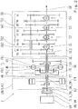
- Fig. 1 shows a drive device of a vehicle with a dual-clutch transmission 1, which has a multi-stage automatic transmission SG with two partial transmissions TG1, TG2, a starting retarder AR, a dual clutch DK with two friction clutches K1, K2, a vibration damper TD and an internal combustion engine VM.
- the manual transmission SG is formed in countershaft design and comprises a total of seven forward gears G1, G2, G3, G4, G5, G6, G7 and a reverse gear RG, which are switchable via four double-sided switching packets S1, S2, S3, S4. Since the construction of a countershaft transmission known per se and the operation of the individual designed as idler gears and fixed gears gears such a transmission for the invention is irrelevant, is omitted to simplify an explicit designation of the individual gears.
- the first partial transmission TG1 provides a gear group with the odd gears G1, G3, G5 G7 and the reverse gear RG.
- the second partial transmission TG2 provides a gear group with the even gears G2, G4, G6.
- the double clutch DK is basically a zugkraftunterbrechungsbuild sequential shift sequence feasible, with one gear is active in one of the two subtransmission TG1, TG2 and in the other subtransmission TG1, TG2 a subsequent gear is selected.
- the gear change takes place in a known manner by intersecting opening and closing of the two clutches K1, K2.
- the two partial transmissions TG1, TG2 each have a separate transmission input shaft GE 1, GE2 and a common transmission output shaft GA.
- the two transmission input shafts GE1, GE2 are arranged coaxially with each other, wherein a first transmission input shaft GE1, which is associated with the first partial transmission TG1, is formed as an outer hollow shaft, in which the second transmission input shaft GE2, which is associated with the second partial transmission TG2, is arranged as an inner shaft, and emerges from this transmission side.
- the forward gears G1, G2, G3, G4, G5, G6, G7 are each arranged in a wheel plane with two gears meshing with each other.
- the reverse gear RG also has a direction of rotation reversal.
- the gearwheels designed as idler gears are arranged on the transmission output shaft GA and can be connected in a rotationally fixed manner to the latter via the respective switching device S1, S2, S3, S4.
- the gear wheels of the two partial transmissions TG1, TG2 designed as fixed gears are located in each case on a countershaft VW1, VW2.
- the two countershafts VW1, VW2 are arranged coaxially with one another, wherein the short second countershaft VW2 is assigned to the second partial transmission TG2 and is arranged as a hollow shaft over the inner first countershaft VW1, which is assigned to the first partial transmission TG1, and emerges from the hollow shaft on both sides.
- the transmission input shaft GE1 of the first partial transmission TG1 is drive-connected to the associated first countershaft VW1 via an input constant EK with two toothed gears in mesh.
- the transmission input shaft GE 2 of the second subtransmission is drive-connected to the associated second countershaft VW2 via the first gear plane of the second subtransmission TG2.
- the transmission input shaft GE 2 of the second partial transmission TG2 is directly connectable to the transmission output shaft GA. Consequently, the sixth gear, which, as in Fig. 1 can be seen, the first gear plane of the second subtransmission TG2 is assigned, designed as a direct gear.
- the second partial transmission TG2 thus allows a direct gear bypassing the Anfahrretarders AR, ie without torque losses by meshing of the planetary gearset PS and without drag torque losses through the fluid coupling HK.
- the two clutches K1, K2 are combined in a double clutch DK.
- the clutch input sides are drive-connected via a common clutch basket and via a common clutch input shaft K_AN to a drive shaft AN_VM of an internal combustion engine VM.
- For vibration damping is disposed between the double clutch DK and the internal combustion engine VM a vibration damper TD.
- the first clutch K1, which is assigned to the first partial transmission TG1 is connected on the output side via an output shaft K1_AB in a rotationally fixed manner to an input element HR of the starting retarder AR described below.
- the second clutch K2, which is assigned to the second partial transmission TG2 is connected on the output side directly to the second transmission input shaft GE2 in a torque-proof manner.
- the starting retarder AR is arranged between the double clutch DK and the manual transmission SG and comprises a hydrodynamic transmission element HK and a planetary gearset PS.
- the planetary gearset PS has an outer ring gear HR as an input element, a central sun gear SR and a planet carrier PT, wherein the planet carrier PT a plurality with the ring gear HR and the sun gear SR meshing planetary gears PR leads.
- the hydrodynamic transmission element HK comprises a first functional wheel FR1 and a second functional wheel FR2.
- the two functional wheels FR1, FR2 are formed as paddle wheels, which face each other and are rotatably arranged. They form a not-shown, usually toroidal working space FL, which can be filled via a hydraulic circuit, not shown, with a fluid, such as oil. The loading and unloading of the working space FL with the fluid can be regulated via the hydraulic circuit.
- a switching element B is arranged between the first functional wheel FR1 and a non-rotatably mounted component GH, for example a housing.
- the switching element B is in Fig. 1 However, it can also be designed as a frictional brake and is therefore also referred to below as a brake.
- the planetary gear set PS and the hydrodynamic transmission element HK are coupled together.
- the ring gear HR of the planetary gearset PS is rotatably connected to the first clutch K1.
- the sun gear SR is connected to the first functional wheel FR1 and, together with the functional wheel FR1 through the Switching element B on the housing GH festbremsbar or detectable.
- the planet carrier PT is connected to the first transmission input shaft GE1 and thus to the first part transmission TG1 of the vehicle transmission SG and to the second functional wheel FR2.
- the hydrodynamic transmission element HK is thus connected between the sun gear SR and the planet carrier PT.
- the speed of the sun gear SR decreases towards zero.
- the switching element or the brake B is loaded without load.
- the transmission capability of the fluid coupling HK is lowered by emptying or partial emptying of the working space FL.
- the brake B thus now supports the transmitted torque. Consequently, the torque of the engine VM is increased.
- the torque of the internal combustion engine VM is lowered in order to keep the transmission input torque on the first partial transmission TG1 constant.
- the open brake B can be synchronized as follows. Initially, the second clutch K2 is closed and a gear engaged in the second partial transmission TG2. The first partial transmission TG1 is switched to neutral, the first clutch K1 is opened and the fluid coupling HK empties, that is, except for a small drag torque, which possibly causes the sun gear SR to rotate easily, torque-free. Subsequently, a gear in the first partial transmission TG1 is inserted. The gear must have a suitable long gear ratio, so that the planet carrier PT rotates sufficiently slower than the drive shaft AW of the engine VM. This is necessary so that the sun gear SR can reach zero speed as a result.
- the first clutch K1 is slightly operated in the closing direction to transmit a small torque sufficient to accelerate the ring gear HR.
- the sun gear SR slows down and reaches the speed zero or a speed approximately zero at which the brake B is engaged.
- the first clutch K1 is opened again to complete the synchronization of the brake element B.
- the second partial transmission TG2 allows a driving operation with decoupled Anfahrretarder AR to avoid drag losses.
- the first clutch K1 and the brake B can be opened, the sun gear SR then turns freely with, the fluid coupling HK consequently produces no drag losses.
- a complete decoupling of the Anfahrretarders AR is possible by the first partial transmission TG1 switched to neutral and the first clutch K1 is opened.
- the switching element of the brake B can then remain engaged, so that its renewed synchronization is eliminated.
- the starting retarder AR is a retarder, ie a retarder.
- a braking operation can be carried out by the input shaft GE1 of the first partial transmission TG1 is braked with filled fluid coupling HK, wherein in the partial transmission TG1 a gear is engaged. If no gear is engaged in the first partial transmission TG1 and a gear is engaged in the second partial transmission TG2, a braking operation can be carried out via the closed double clutch DK, that is to say the first clutch K1 closed and the second clutch K2 closed.
- Fig. 2 shows a drive device of an unclaimed vehicle with a hybrid transmission 2 with the capacity for electrical traction assistance and the starting retarder AR.
- a hybrid module EX / X / K2 is provided instead of the double clutch module DK .
- the hybrid module EX / X / K2 comprises an electric machine EM, a clutch K2 and a coupling switching element X.
- a drive shaft AN_EM of the electric machine EM which is connected to the rotor of the electric machine EM, is connected to the input element, ie the ring gear HR of FIG Planetenradsatzes PS rotatably connected.
- the clutch K2 is arranged between the electric machine EM and the internal combustion engine VM.
- the coupling switching element X is arranged between the clutch K2 and the electric machine EM.
- the coupling switching element X allows a switchable direct connection of the two transmission input shafts GE1, GE2 with each other.
- the start of the deactivated combustion engine VM can be done with the receipt of the tensile force in the drive train and with a slip decoupling.
- the vehicle is initially in a purely electric motor driven driving operation.
- the brake B is engaged, in the first partial transmission TG1 a gear is engaged, the clutch K2 is open.
- the coupling switching element X is inserted. It follows a load build-up on the fluid coupling HK as already described, so that the brake B is free of load and can be designed. Since the output torque decreases because of the reduction of the momentary increase by the planetary gearset PS, the drive torque of the electric machine EM can be increased accordingly, as far as available, to compensate. This is followed by the start of the internal combustion engine VM via the clutch K2.
- the fluid coupling HK dampens any fluctuations in the transmission of the starting torque. Subsequently, a synchronization of the brake B under load by a suitable control of the torques of the engine VM, the electric machine EM and possibly the fluid coupling HK done. Finally, a load reduction takes place at the fluid coupling HK, at the same time the moments of the internal combustion engine VM and the electric machine EM are adapted to achieve a desired torque curve at the output.
- the electric machine EM can support load circuits.
- the electric machine EM supports the output torque via the first partial transmission TG1, while an internal combustion engine-driven gear change takes place.
- the gear change can take place in the second partial transmission TG2.
- the internal combustion engine can be coupled via the coupling switching element X to the first partial transmission TG1 and there the gear change take place.
- the necessary synchronization of these circuits if present, via synchronizations on the coupling element X and / or on the switching packets S1, S2 of the second partial transmission TG2 done.
- the respectively relevant switching elements S2, S3, S4 of the first partial transmission TG1 are synchronized by means of the electric machine EM.
- a purely electric motor driven driving load circuits can be done using the flow coupling HK.
- an upshift in a driving operation via the second partial transmission TG2 shown by closing the coupling element X with the clutch K2 open and brake B open, a subsequent gear can be inserted in the first OperagetriebeTG1.
- the fluid coupling HK takes over the load, so that the second subtransmission TG2 is free of load and the gear of the second subtransmission TG2 can be designed.
- the brake B can be synchronized and inserted.
- the upshift it is basically possible to start the engine VM by utilizing the released flywheel energy of the electric machine EM.
- a train downshift is also possible. In addition to this, turn to the already mentioned DE 10 2010 030 569 A1 the applicant and those already mentioned DE 10 2010 061 827 A1 directed.
- Fig. 3 shows a with the dual clutch transmission 1 of Fig. 1 comparable dual-clutch transmission 3 with a starting retarder AR '.
- a hydrodynamic torque converter HD is provided here. This additionally has a third, fixed functional wheel FR3, which causes a hydrodynamic torque increase of the drive torque as a stator.
- Fig. 4 shows an unclaimed hybrid drive 4 with such a torque converter HD.
- the operation is analogous to that at Fig.1 respectively.
- Fig. 2 described functions.
- an instantaneous adjustment of the internal combustion engine VM or of the electric machine EM in a load transition from the hydrodynamic transmission element HD to the brake B and vice versa is not necessary here.
- the Fig. 5 and the Fig. 6 show a further double-clutch transmission 5 or a further unclaimed hybrid transmission 6.
- a double-flow starting retarder AR is arranged The construction and the mode of operation of such a starting retarder are per se from the above-mentioned DE 198 17 865 A1 known. Therefore, the description is limited here to the connection to the dual-clutch transmission 5 and the hybrid transmission. 6
- the double-entry starting retarder AR has a hydrodynamic transmission element HB with two first, fixed functional wheels STa, STb and a second, rotatable functional wheel RT
- the two stators STa, STb are axially opposite each other, between which the rotor RT is arranged , STb form with the rotor RT in each case a working space FLa, FLb or in each case a hydraulic circuit for both possible directions of rotation of the rotor RT
- a planetary gearset PS as in the Anfahrretardern of Fig. 1 and Fig. 3 intended.
- a lock-up clutch UK is provided. This eliminates the brake B.
- the ring gear HR of the planetary gearset PS is connected to the output shaft K1_AB the first clutch K1.
- the sun gear SR is connected to the rotor RT of the hydrodynamic transmission element HB connected.
- the planet carrier PT is the output side connected to the first transmission input shaft GE1.
- the sun gear SR can be coupled to the planet carrier PT via the bridging clutch UK.
- a hydrodynamic starting function can be used when the lock-up clutch UK is open, and a hydrodynamic retarder function can be shown when the lock-up clutch UK is closed.
- the sun gear SR is increasingly braked in a filled working space FLa or FLb, and a transmission input torque is correspondingly built up on the first transmission input shaft GE1. Due to the stationary second functional wheel (rotor RT), torque is increased.
- the sun gear SR can be hydrodynamically braked to almost standstill.
- the starting process can then be completed by closing the lock-up clutch UK, whereby the planetary gearset PS merges into a block circulation. With emptied retarder HB, the retarder position switched by the bridging clutch UK is inactive.
- the lock-up clutch UK can be closed without load when the gear is laid out in the first sub-transmission TG1.
- the lock-up clutch could then be switched as a synchronized clutch, or be designed accordingly.
- the ring gear HR is connected to the drive shaft AN_EM the electric machine EM
- the sun gear SR is connected to the second functional gear of the hydrodynamic transmission element HB, ie with the rotor RT
- the planet carrier PT is the output side connected to the first transmission input shaft GE1
- the sun gear SR connected to the rotor RT can be coupled to the planet carrier PT via the bridging clutch UK, so that a hydrodynamic starting function can be used when the lockup clutch UK is open and a hydrodynamic retarder function can be used when the lockup clutch UK is closed.
- the hybrid transmission 6 allows a hydrodynamic starting in purely electric motor driven driving operation. Also, a mechanical starting process is possible, now instead of the dropped brake B, the lock-up clutch UK is closed.
- the clutch K2 of the second partial transmission TG2 can be open in order to avoid drag losses. From a generator mode can be approached without delay. In a generator mode, a continuous creep mode can be used.
- the internal combustion engine VM can be started with traction power and slip decoupling. Load circuits with electromotive assistance are possible, as well as load circuits in purely electric motor driven driving operation with the help of the lock-up clutch UK are possible.
- Fig. 7 shows a non-claimed hybrid transmission 7, which is largely identical to the hybrid transmission of Fig. 2 is.
- the hydraulic fluid pump P can also be operated during vehicle standstill.
- a separately driven pump may be omitted if necessary.
- the dual-clutch module is arranged upstream of the starting retarder AR, AR ', AR " Fig. 8
- a further drive device with a dual-clutch transmission 8, in which alternatively two single clutches K1 ', K2' between the Anfahrretarder AR and the gearbox SG are arranged.
- this dual clutch transmission 8 with Anfahrretarder and with the Anfahrretarder AR drivably downstream dual clutch DK ', the sun SR of the planetary PS is connected to the first functional FR1 of the hydrodynamic transmission element HK and fixed via the switching element B to the non-rotatable component GH.
- the ring gear HR is drive-connected to the engine VM and connected to a clutch input shaft K2'_AN of the second clutch K2 '.
- the planet carrier PT is on the drive side rotatably connected to the second functional wheel FR2 and the output side connected to a clutch input shaft K1'_AN the first clutch K1 '.
- the operation is as in the dual-clutch transmission 1 of Fig. 1 ,
Description
Die Erfindung betrifft eine Antriebsvorrichtung eines Fahrzeugs gemäß dem Oberbegriff des Patentanspruchs 1, sowie ein Verfahren zu dessen Betrieb gemäß dem Oberbegriff des Patentanspruchs 9. Antriebsvorrichtungen von Fahrzeugen mit Schaltgetrieben, die zwei Teilgetriebe oder in ihrer Funktionsweise vergleichbare getrennte, meist automatisch oder automatisiert schaltbare Getriebestränge umfassen, sind bereits bekannt. Bestimmte Funktionen eines solchen Antriebs sind in der Regel nur jeweils einem der beiden Teilgetriebe zugeordnet oder über dieses darstellbar, so dass unsymmetrische Beanspruchungen an den Teilgetrieben auftreten können oder bestimmte Funktionen sich gegenseitig ausschließen oder nur mit Einschränkungen zur Verfügung stehen.The invention relates to a drive device of a vehicle according to the preamble of
Bei einem Doppelkupplungsgetriebe wird beispielsweise meistens eine von zwei eingangsseitigen Lastschaltkupplungen auch stets als Anfahrkupplung eingesetzt, da sich der bevorzugte Anfahrgang in dem betreffenden Teilgetriebe befindet. Unterliegt der Antrieb häufigen Anfahrvorgängen, wie beispielsweise bei einem Stadtbus, kann dies zu einer thermischen Überlastung mit vorzeitigem Verschleiß der betreffenden Kupplung führen.In a dual-clutch transmission, for example, usually one of two input-side power shift clutches always used as a starting clutch, since the preferred starting gear is located in the respective partial transmission. If the drive is subjected to frequent start-up procedures, such as in the case of a city bus, this can lead to thermal overload with premature wear of the relevant clutch.
Bei einem aus einem Doppelkupplungsgetriebe abgeleiteten oder ähnlichen Hybridantrieb können Funktionszuordnungen der Teilgetriebe bestimmte Einschränkungen bedingen. So ist es beispielsweise aus einem Generatorbetrieb einer einem der Teilgetriebe zugeordneten elektrischen Maschine heraus nicht möglich, verzögerungsfrei in einen Anfahrvorgang zu wechseln. Ebenso ist während eines Generatorbetriebs in der Regel kein Dauerkriechen möglich, also ein Fahren mit konstanter niedriger Geschwindigkeit. Weitere Einschränkungen können sich beim Starten des Verbrennungsmotors ausgehend von einem elektrischen Fahrbetrieb ergeben. Ein Start des Verbrennungsmotors mit Erhalt der Zugkraft im Antriebsstrang bedingt in der Regel eine zweite elektrische Maschine als Startergenerator oder eine zusätzliche Reibungskupplung, die dann jedoch für häufig wiederkehrende Anfahrvorgänge entsprechend groß ausgelegt sein muss.In a derived from a dual clutch transmission or similar hybrid drive function assignments of the partial transmission can cause certain restrictions. Thus, it is not possible, for example, from a generator operation of an electric machine assigned to one of the partial transmissions to change into a starting process without delay. Similarly, during a generator operation usually no permanent crawl is possible, so driving at a constant low speed. Further restrictions may arise when starting the internal combustion engine starting from an electric driving operation. A start of the internal combustion engine with retention of traction in the drive train usually requires a second electric machine as a starter generator or an additional Friction clutch, which must then be designed to be large enough for frequently recurring starting operations.
Weiterhin ist es bekannt, Fahrzeuggetriebe, die hohen Belastungen ihrer Anfahr- und Bremseinrichtungen unterliegen, wie beispielsweise Lastschaltautomatgetriebe für Stadtbusse, bei denen häufige, kurz aufeinanderfolgende Anfahr- und Bremsvorgänge vorkommen, mit einem hydrodynamischen Drehmomentwandler als verschleißfreiem Anfahrelement und gegebenenfalls mit einer zusätzlichen verschleißfreien Dauerbremseinrichtung wie einem hydrodynamischen Retarder auszustatten. Bei solchen hydrodynamischen Übertragungselementen wird die mechanische Energie einer Antriebswelle unter Wärmeerzeugung in die kinetische Energie eines Fluids und wieder zurück in die mechanische Energie einer Abtriebswelle umgewandelt. Eine einfache Strömungskupplung mit einem antreibenden Pumpenrad und einem abtreibenden Turbinenrad wirkt dabei wie ein stufenloses Getriebe mit einer eingangs- und ausgangseitigen Drehzahldifferenz. Bei einem Drehmomentwandler sorgt ein zusätzliches Leitrad durch eine Umlenkung der Strömung in Richtung Pumpenrad für eine Momentenüberhöhung bei der Drehmomentwandlung. Bei einem Retarder wird durch ein feststehendes Schaufelrad, den Stator, eine Bremswirkung auf das antreibende Rad, den Rotor, erzeugt und dadurch eine Bremswirkung auf den Antriebsstrang bewirkt.Furthermore, it is known that vehicle transmissions which are subject to high loads on their starting and braking devices, such as powershift transmissions for city buses, where frequent, briefly successive start-up and braking occur with a hydrodynamic torque converter as a wear-free starting element and optionally with an additional wear-free permanent braking device to equip a hydrodynamic retarder. In such hydrodynamic transmission elements, the mechanical energy of a drive shaft is converted with the generation of heat into the kinetic energy of a fluid and back into the mechanical energy of an output shaft. A simple fluid coupling with a driving impeller and a driven turbine wheel acts as a continuously variable transmission with an input and output side speed difference. In a torque converter, an additional stator by a deflection of the flow in the direction of impeller ensures a torque increase in the torque conversion. In a retarder, a fixed paddle wheel, the stator, creates a braking action on the driving wheel, the rotor, thereby causing a braking effect on the drive train.
Um den erforderlichen baulichen Aufwand und die Herstellkosten gering zu halten, sind bereits sogenannte Anfahrretarder bekannt, welche die Funktionen eines hydrodynamischen Anfahrelements, wie eine Strömungskupplung oder einen Drehmomentwandler, und eines hydrodynamischen Retarders in einer Baueinheit kombinieren.In order to keep the required structural complexity and the production costs low, so-called starting retarders are already known, which combine the functions of a hydrodynamic starting element, such as a fluid coupling or a torque converter, and a hydrodynamic retarder in a structural unit.
Bei einem aus der
Aus der
Aus der
Aus der
Aus der
Vor diesem Hintergrund liegt der Erfindung die Aufgabe zugrunde, eine verbesserte Antriebsvorrichtung eines Fahrzeugs mit Teilgetrieben zu schaffen, der insbesondere im Hinblick auf häufige Anfahr- und Anhaltvorgänge komfortabel und langlebig ist. Eine weitere Aufgabe ist es, ein Verfahren zum Betrieb einer solchen Antriebsvorrichtung anzugeben.Against this background, the invention has the object to provide an improved drive device of a vehicle with partial transmissions, which is comfortable and durable, especially with regard to frequent startup and stopping operations. Another object is to provide a method for operating such a drive device.
Die Lösung dieser Aufgabe ergibt sich aus den Merkmalen der unabhängigen Patentansprüche, während vorteilhafte Ausgestaltungen und Weiterbildungen der Erfindung den Unteransprüchen entnehmbar sind.The solution of this problem arises from the features of the independent claims, while advantageous embodiments and modifications of the invention are the dependent claims.
Der Erfindung liegt die Erkenntnis zugrunde, dass ein Fahrzeuggetriebe, beim dem eine Eingangskupplung sowohl als Lastschalt-mittel als auch als Anfahrmittel eingesetzt wird, wie bei Doppelkupplungsgetrieben und Hybridgetrieben üblich, durch ein zusätzliches hydrodynamisches Anfahrelement ergänzt werden kann. Ein solches hydrodynamisches Anfahrelement, welches an einem Getriebepfad mit einem Anfahrgang wirksam ist, kann die besagte Lastschaltkupplung bzw. die elektrische Maschine von der Funktion eines Anfahrelements entkoppeln. Die Lastschaltkuppiung ist damit im Fahrbetrieb gegen erhöhten Verschleiß geschützt beziehungsweise flexibler einsetzbar.The invention is based on the finding that a vehicle transmission in which an input clutch is used both as a load switching means and as a starting means, as usual in dual-clutch transmissions and hybrid transmissions, can be supplemented by an additional hydrodynamic starting element. Such a hydrodynamic starting element, which is effective on a gear path with a starting gear, can decouple said power-shift clutch or the electric machine from the function of a starting element. The Lastschaltkuppiung is thus protected while driving against increased wear or flexible use.
Demnach geht die Erfindung aus von einer Antriebsvorrichtung eines Fahrzeugs, mit einem Verbrennungsmotor und mit einem Getriebe, das als mehrstufiges Schaltgetriebe mit zwei Teilgetrieben und jeweils einer separaten Getriebeeingangswelle ausgebildet ist, wobei einer ersten Getriebeeingangswelle eines ersten Teilgetriebes eine erste Kupplung, über die die erste Getriebeeingangswelle mit dem Verbrennungsmotor triebverbindbar ist, und wobei einer zweiten Getriebeeingangswelle eines zweiten Teilgetriebes eine zweite Kupplung zugeordnet ist, über die die zweite Getriebeeingangswelle mit dem Verbrennungsmotor triebverbindbar ist.Accordingly, the invention is based on a drive device of a vehicle, with an internal combustion engine and with a transmission which is designed as a multi-stage transmission with two partial transmissions and a separate transmission input shaft, wherein a first transmission input shaft of a first partial transmission, a first clutch via which the first transmission input shaft with the internal combustion engine is drive-connected, and wherein a second transmission input shaft of a second sub-transmission, a second clutch is assigned, via which the second transmission input shaft is drivverbindverbindbar with the internal combustion engine.
Zur Lösung der gestellten Aufgabe bezüglich der Vorrichtung sieht die Erfindung vor, dass der ersten Getriebeeingangswelle zusätzlich ein Anfahrelement zugeordnet ist, das zumindest ein hydrodynamisches Übertragungselement aufweist, welches ein erstes Funktionsrad und ein zweites Funktionsrad aufweist, die einen mit Fluid befüllbaren Arbeitsraum zur Erzeugung eines hydrodynamischen Übertragungsmoments bilden, so dass mit Hilfe des Anfahrelements zumindest eine Anfahrfunktion realisierbar ist, die auf das erste Teilgetriebe wirksam ist.To solve the object with respect to the device, the invention provides that the first transmission input shaft is additionally assigned a starting element, which has at least one hydrodynamic transmission element, which has a first functional wheel and a second functional wheel, which can be filled with fluid working space for generating a hydrodynamic Form transmission torque, so that with the help of the starting element at least one starting function is realized, which is effective on the first partial transmission.
Zum Betreiben einer Antriebsvorrichtung eines Fahrzeugs, mit einem Verbrennungsmotor und mit einem Getriebe, das als mehrstufiges Schaltgetriebe mit zwei Teilgetrieben und jeweils einer separaten Getriebeeingangswelle ausgebildet ist, wobei einer ersten Getriebeeingangswelle eines ersten Teilgetriebes eine erste Kupplung, über die die erste Getriebeeingangswelle mit dem Verbrennungsmotor triebverbindbar ist, und wobei einer zweiten Getriebeeingangswelle eines zweiten Teilgetriebes eine zweite Kupplung zugeordnet ist, über die die zweite Getriebeeingangswelle mit dem Verbrennungsmotor triebverbindbar ist, sieht die Erfindung vor, dass mittels eines Anfahrelements zumindest eine hydrodynamische Anfahrfunktion durchgeführt wird, wobei das Anfahrelement der ersten Getriebeeingangswelle zugeordnet ist und ein hydrodynamisches Übertragungselement aufweist, welches ein erstes Funktionsrad und ein zweites Funktionsrad aufweist, die einen mit Fluid befüllbaren Arbeitsraum zur Erzeugung eines hydrodynamischen Übertragungsmoments bilden.For operating a drive device of a vehicle, with an internal combustion engine and with a transmission which is designed as a multi-stage transmission with two partial transmissions and a separate transmission input shaft, wherein a first transmission input shaft of a first partial transmission, a first clutch, via which the first transmission input shaft to the internal combustion engine drivverbindverbindbar is, and wherein a second transmission input shaft of a second partial transmission, a second clutch is assigned, via which the second transmission input shaft is drivingly connected to the internal combustion engine, the invention provides that at least one hydrodynamic starting function is performed by means of a starting element, wherein the starting element associated with the first transmission input shaft is and has a hydrodynamic transmission element, which has a first functional wheel and a second Has functional wheel, which form a fluid-filled working space for generating a hydrodynamic transmission torque.
Diese Antriebsvorrichtung weist demnach ein Basisgetriebe mit zwei Teilgetrieben auf, bei dem an der Eingangswelle eines der beiden Teilgetriebe ein hydrodynamisches Anfahrelement angeordnet ist. Dadurch können die eingangs erwähnten unsymmetrische Belastungen oder Funktionseinschränkungen konventioneller Antriebsvorrichtungen weitestgehend vermieden werden, wodurch sich der Fahrkomfort verbessert und der Verschleiß verringert. Die Ausbildung der Antriebsvorrichtung mit zwei Teilgetrieben ermöglicht die Umgehung des hydrodynamischen Anfahrelements bei einem Fahrbetrieb bei Nutzung des zweiten Teilgetriebes, wodurch sich der Wirkungsgrad und die Wirtschaftlichkeit der Antriebsvorrichtung gegenüber einem Getriebe, bei dem ein hydrodynamisches Anfahrelement stets in den Leistungspfad einbezogen ist, verbessert. Das Basisgetriebe, bestehend aus dem Getriebe mit den zwei Teilgetrieben und dem hydrodynamischen Anfahrelement, ist insbesondere mit einem Doppelkupplungsmodul oder in einer nicht beanspruchten Variante auch mit einem Hybridmodul kombinierbar.Accordingly, this drive device has a base transmission with two partial transmissions, in which a hydrodynamic starting element is arranged on the input shaft of one of the two partial transmissions. As a result, the above-mentioned unbalanced loads or functional limitations of conventional drive devices can be largely avoided, which improves ride comfort and reduces wear. The design of the drive device with two partial transmissions allows the circumvention of the hydrodynamic starting element in a driving operation when using the second sub-transmission, whereby the efficiency and economic efficiency of the drive device over a transmission in which a hydrodynamic starting element is always included in the power path improves. The basic transmission, consisting of the transmission with the two partial transmissions and the hydrodynamic starting element, can also be combined with a dual-clutch module or, in a variant not claimed, also with a hybrid module.
Das Basisgetriebe kann somit als Baukastenkomponente für ein Doppelkupplungsgetriebe genutzt werden, bei dem die Doppelkupplung als Lastschaltvorrichtung für eine zugkraftunterbrechungsfreie sequenzielle Schaltabfolge dient. Die Doppelkupplung bzw. eine der beiden Lastschaltkupplungen wird dabei nicht als Anfahrelement benötigt und somit auch nicht durch häufig wiederkehrende Anfahrvorgänge überbeansprucht. Diese Funktion erfüllt das hydrodynamische Anfahrelement, das ein verschleißfreies Anfahren in einem Gang des zugehörigen Teilgetriebes ermöglicht.The base gear can thus be used as a modular component for a dual-clutch transmission, in which the dual clutch is used as a load switching device for a zugkraftunterbrechungsfreie sequential switching sequence. The dual clutch or one of the two powershift clutches is not required as a starting element and thus not overstrained by frequently recurring starting operations. This function fulfills the hydrodynamic starting element, which enables a wear-free starting in a gear of the associated sub-transmission.
Das Basisgetriebe kann in einer nicht beanspruchten Variante auch als Baukastenkomponente für einen Hybridantrieb genutzt werden, bei dem eine elektrische Maschine, welche einem der beiden Teilgetriebe zugeordnet ist, eine Schaltfolge mit elektrischer Zugkraftunterstützung ermöglicht, indem diese elektrische Maschine eine entsprechende Lastschaltkupplung ersetzt. Die Anfahrfunktion wird wiederum durch das hydrodynamische Anfahrelement erfüllt. Dies hat den Vorteil, dass die elektrische Maschine unabhängig von einem Anfahrvorgang als Generator zum Aufladen eines elektrischen Speichers und/oder zur Versorgung elektrischer Verbraucher im Bordnetz betrieben werden kann.The base gear can be used in a not claimed variant as a modular component for a hybrid drive, in which an electric machine which is assigned to one of the two partial transmission, a switching sequence with electrical traction assistance allows by this electric machine replaces a corresponding power shift clutch. The starting function is again fulfilled by the hydrodynamic starting element. This has the advantage that the electric machine is independent of a startup process can be operated as a generator for charging an electrical storage and / or for supplying electrical consumers in the electrical system.
Das Anfahrelement ist gemäß einer ersten beanspruchten Alternative als ein Anfahrretarder ausgebildet, mit einem hydrodynamischen Übertragungselement mit einem ersten drehbaren Funktionsrad und einem zweiten drehbaren Funktionsrad, mit einem Planetenradsatz mit einem Hohlrad, einem Sonnenrad und einem Planetenträger, wobei der Planetenträger mehrere Planetenräder führt, die mit dem Sonnenrad und dem Hohlrad im Verzahnungseingriff stehen, und mit einem Schaltelement zur Fixierung eines der beiden Funktionsräder, wobei das hydrodynamische Übertragungselement sowie der Planetenradsatz miteinander gekoppelt sind und gemeinsam eine Baueinheit bilden. Das Schaltelement kann als ein einfaches formschlüssiges Klauenschaltelement oder als eine reibschlüssige Bremse ausgebildet sein.The starting element is designed according to a first claimed alternative as a starting retarder, with a hydrodynamic transmission element with a first rotatable functional wheel and a second rotatable functional wheel, with a planetary gear with a ring gear, a sun gear and a planet carrier, wherein the planet carrier carries a plurality of planetary gears with the sun gear and the ring gear are in meshing engagement, and with a switching element for fixing one of the two functional wheels, wherein the hydrodynamic transmission element and the planetary gear set are coupled together and together form a structural unit. The switching element may be formed as a simple form-locking claw switching element or as a frictional brake.
Nach einer Ausführungsform des Verfahrens kann vorgesehen sein, dass ein Anfahren mittels eines solchen Anfahrretarders durchgeführt wird, indem durch Befüllen des Arbeitsraums des Anfahrretarders ein hydrodynamisches Übertragungsmoment aufgebaut wird. Dabei ist eines der beiden Planetenradsatzelemente Hohlrad oder Sonnenrad als ein Antriebselement des Planetenradsatzes wirksam, welches durch den Antriebsmotor angetrieben wird. Das andere der beiden Planetenradsatzelemente Hohlrad oder Sonnenrad, welches mit dem ersten Funktionsrad drehfest verbunden ist und über das Schaltelement an einem drehfesten Bauteil feststellbar ist, wird bei einem Nulldurchgang seiner Drehzahl durch Schließen des Schaltelements festgestellt. Der Planetenträger, welcher mit dem zweiten Funktionsrad drehfest verbunden ist, ist als ein Abtriebselement des Planetenradsatzes wirksam, das die Getriebeeingangswelle des ersten Teilgetriebes antreibt.According to one embodiment of the method can be provided that a start is carried out by means of such Anfahrretarders by a hydrodynamic transmission torque is established by filling the working space of the Anfahrretarders. In this case, one of the two Planetenradsatzelemente ring gear or sun gear is effective as a drive element of the planetary gear, which is driven by the drive motor. The other of the two Planetenradsatzelemente ring gear or sun gear, which is rotatably connected to the first functional and is detectable via the switching element on a non-rotatable component is detected at a zero crossing of its speed by closing the switching element. The planetary carrier, which is rotatably connected to the second functional wheel, is effective as an output element of the planetary gear, which drives the transmission input shaft of the first partial transmission.
Wenn der Arbeitsraum mit Fluid gefüllt oder teilgefüllt und das Schaltelement geöffnet ist, ist der Anfahrretarder als eine Strömungskupplung ohne Momentüberhöhung wirksam. Wenn der Arbeitsraum mit Fluid gefüllt oder teilgefüllt und das Schaltelement geschlossen ist, ist der Anfahrretarder als Retarder wirksam. Durch eine geeignete Kopplung mit dem Planetenradsatz wird erreicht, dass das Vorzeichen der Differenzdrehzahl an der Strömungskupplung im Anfahrbetrieb und im Retarderbetrieb gleich ist. Daher ist keine vergleichsweise aufwendige doppelflutige Auslegung der Strömungskupplung für beide Drehrichtungen erforderlich.When the working space is filled with fluid or partially filled and the switching element is opened, the starting retarder is effective as a fluid coupling without torque escalation. When the working space is filled with fluid or partially filled and the switching element is closed, the starting retarder is effective as a retarder. By a suitable coupling with the planetary gear set is achieved that the sign of the differential speed at the fluid coupling in startup and retarder operation is the same. Therefore, no comparatively complicated double-flow design of the fluid coupling for both directions of rotation is required.
Entgegen den herkömmlichen Anfahrretardern bleibt bei dem Anfahrretarder gemäß der Erfindung eine Differenzdrehzahl zwischen den Funktionsrädern bestehen, wobei sich mit der Befüllung des Arbeitsraums das entgegen der Drehrichtung der Antriebsquelle rückwärts drehende antreibende Funktionsrad einem Nulldurchgang seiner Drehzahl annähert, während die Drehzahl des abtreibenden Funktionsrads mit der zugehörigen Getriebeeingangswelle entsprechend ansteigt, worauf sich das Fahrzeug bei eingelegtem Anfahrgang entsprechend in Bewegung setzt.Contrary to the conventional Anfahrretardern remains at the Anfahrretarder according to the invention, a differential speed between the functional wheels, with the filling of the working space counter to the direction of rotation of the drive source backwards rotating driving function wheel approaches a zero crossing of its speed, while the speed of the abortive function wheel with the associated Accordingly, the transmission input shaft correspondingly increases, whereupon the vehicle is set in motion when the starting gear is engaged.
Ist ein entsprechend festgelegtes Drehzahlfenster bei einer Drehzahl annähernd Null erreicht, kann das Schaltelement lastfrei eingelegt werden, wodurch das zugehörige Funktionsrad festgebremst wird. Das hydrodynamische Übertragungselement ist dadurch von einer Strömungskupplungsstellung in eine Retarderstellung umgeschaltet. Wenn der Arbeitsraum anschließend entleert und der Retarder damit deaktiviert ist, wirkt der Planetenradsatz wie eine feste Eingangsübersetzung des betreffenden Teilgetriebes.If a correspondingly fixed speed window is reached at a speed approaching zero, the shift element can be loaded without load, whereby the associated function wheel is braked. The hydrodynamic transmission element is thereby switched over from a fluid coupling position to a retarder position. If the working space is subsequently emptied and the retarder is thus deactivated, the planetary gearset acts as a fixed input gear ratio of the relevant subtransmission.
Außerdem kann bei dem Verfahren vorgesehen sein, dass ein Antriebsmoment des Verbrennungsmotors entsprechend abgesenkt wird, wenn nach dem Schließen des Schaltelements, durch zumindest teilweises Entleeren des Arbeitsraums das hydrodynamische Übertragungsmoment abgebaut wird.In addition, it can be provided in the method that a drive torque of the internal combustion engine is lowered accordingly, if after closing the switching element, by at least partially emptying the working space, the hydrodynamic transmission torque is reduced.
Zweckmäßigerweise wird beim Abbau des Übertragungsmoments der Strömungskupplung gleichzeitig das Antriebsmoment des Verbrennungsmotors abgesenkt, um an der Eingangswelle des zugehörigen Teilgetriebes ein konstantes bzw. kontinuierlich veränderliches Getriebeeingangsmoment zu erhalten. Durch das Abbauen des hydrodynamischen Moments bei geschlossenem Schaltelement befindet sich der Anfahrretarder in einer Retarderstellung, er ist aber deaktiviert.Conveniently, while reducing the transmission torque of the fluid coupling, the drive torque of the internal combustion engine is simultaneously lowered in order to obtain a constant or continuously variable transmission input torque at the input shaft of the associated subtransmission. By dismantling of the hydrodynamic torque when the switching element is closed, the starting retarder is in a retarder position, but it is deactivated.
Zum Aktivieren des Retarders kann bei geschlossenem Schaltelement, und dadurch festgestelltem ersten Funktionsrad, durch Befüllen des Arbeitsraums ein hydrodynamisches Übertragungsmoment aufgebaut werden. Dadurch kann eine Bremswirkung auf den Antrieb erzeugt werden. Über eine Dosierung des Füllgrads des Arbeitsraums ist eine Dosierung des Bremsmoments möglich.To activate the retarder, a hydrodynamic transmission torque can be built up by filling the working space when the switching element is closed, and thereby determined first functional wheel. As a result, a braking effect on the drive can be generated. By dosing the degree of filling of the working space a dosage of the braking torque is possible.
Die beiden Teilgetriebe bilden mit dem Anfahrretarder ein Basisgetriebe, dem, im Falle eines Doppelkupplungsgetriebes, eine Doppelkupplung antriebstechnisch vor- oder nachgelagert sein kann.The two sub-transmissions form with the Anfahrretarder a base gear, which, in the case of a dual-clutch transmission, a double clutch drive technology upstream or downstream can be.
Bei einer Ausführungsform kann demnach vorgesehen sein, dass die beiden Teilgetriebe ein Doppelkupplungsgetriebe bilden, bei dem zwei Kupplungen vorhanden sind, wobei jeweils eine Kupplung einem Teilgetriebe zugeordnet ist, wobei die beiden Kupplungen als Doppelkupplung ausgebildet sind, dem Anfahrelement antriebstechnisch vorgelagert sind, eingangsseitig mit dem Verbrennungsmotor antriebsverbunden sind. Ausgangsseitig ist eine erste Kupplung über eine Kupplungsausgangswelle mit einem Eingangselement des Planetenradsatzes drehfest verbunden, während eine zweite Kupplung mit der zweiten Getriebeeingangswelle drehfest verbunden ist.In one embodiment, it can thus be provided that the two partial transmissions form a dual-clutch transmission in which two clutches are present, wherein one clutch is assigned to a partial transmission, wherein the two clutches are designed as a double clutch, the drive element are preceded by drive-off, with the input side Combustion engine are drivingly connected. On the output side, a first clutch is rotatably connected via a clutch output shaft to an input element of the planetary gear, while a second clutch is rotatably connected to the second transmission input shaft.
Weiter kann vorgesehen sein, dass bei einem Doppelkupplungsgetriebe mit Anfahrretarder und mit einer dem Anfahrretarder antriebstechnisch vorgelagerten Doppelkupplung eines der beiden Planetenradsatzelemente Hohlrad oder Sonnenrad mit dem ersten Funktionsrad des hydrodynamischen Übertragungselements drehfest verbunden ist sowie über das Schaltelement an einem ortsfesten Bauteil festsetzbar ist, dass das andere der beiden Planetenradsatzelemente Hohlrad oder Sonnenrad mit einer Ausgangswelle einer ersten Kupplung drehfest verbunden ist, dass der Planetenträger antriebsseitig mit dem zweiten Funktionsrad drehfest verbunden ist, und dass der Planetenträger abtriebsseitig mit der ersten Getriebeeingangswelle drehfest verbunden ist.It can further be provided that in a dual-clutch transmission with Anfahrretarder and with the Anfahrretarder driveably upstream dual clutch one of the two planetary gear ring gear or sun gear is rotatably connected to the first functional wheel of the hydrodynamic transmission element and can be fixed via the switching element to a stationary component that the other the two Planetenradsatzelemente ring gear or sun gear is rotatably connected to an output shaft of a first clutch, that the planetary carrier is rotatably connected on the drive side with the second functional wheel, and the output side of the planet carrier is rotatably connected to the first transmission input shaft.
Dieser Antrieb ermöglicht bei geöffnetem Schaltelement und geschlossener erster Kupplung eine hydrodynamische Anfahrfunktion über das erste Teilgetriebe, wobei die Strömungskupplung das Antriebsmoment des Verbrennungsmotors ohne Momentenüberhöhung überträgt. Während des Anfahrvorgangs, also bei noch offenem Schaltelement, kann bereits eine Lastumschaltung zwischen den beiden Kupplungen erfolgen, um eine möglichst kurze Schaltzeit für einen anschließenden Schaltvorgang zu erreichen. Dies wirkt sich vorteilhaft auf die Performance des Antriebs bei Anfahrvorgängen mit starker Beschleunigung aus.This drive allows for open switching element and closed first clutch hydrodynamic starting function on the first partial transmission, wherein the fluid coupling transmits the drive torque of the internal combustion engine without torque increase. During the starting process, ie with the switching element still open, a load switching between the two clutches can already take place in order to achieve the shortest possible switching time for a subsequent switching operation. This has an advantageous effect on the performance of the drive during startup processes with strong acceleration.
Im Fahrbetrieb in den Gängen des zweiten Teilgetriebes kann der Anfahrretarder vom Antrieb abgekoppelt werden, indem die zugehörige erste Kupplung und das Schaltelement geöffnet werden, oder indem die erste Kupplung geöffnet wird und das erste Teilgetriebe in Neutral geschaltet wird. Dadurch werden unnötige Schleppverluste des Anfahrretarders vermieden. Die zweite Möglichkeit erlaubt, dass das Schaltelement eingelegt bleiben kann, so dass eine Synchronisierung für ein erneutes Einlegen entfällt.When driving in the gears of the second partial transmission, the starting retarder can be disconnected from the drive by the associated first clutch and the switching element are opened, or by the first clutch is opened and the first part transmission is switched to neutral. As a result, unnecessary drag losses of Anfahrretarders be avoided. The second possibility allows that the switching element can remain inserted, so that a synchronization for a renewed insertion is omitted.
Weiterhin ermöglicht das zweite Teilgetriebe die Schaltung eines Direktgangs zum Getriebeeingang durch die zweite Kupplung unter Umgehung des Anfahrretarders, da dieser nur am ersten Teilgetriebe wirksam ist. Folglich ist zur Herstellung einer Direktverbindung zwischen Verbrennungsmotor und Getriebe keine Überbrückungskupplung des Anfahrretarders erforderlich, welche einen Blockumlauf des Planetenradsatzes erzeugen würde. Durch Schalten einer Direktverbindung der zweiten Getriebeeingangswelle mit der Getriebeausgangswelle über eine vorzugsweise vorhandene Schaltkupplung am Getriebeeingang des zweiten Teilgetriebes, kann auch ein Direktgang des Gesamtgetriebes dargestellt werden. Der Direktgang wird nicht durch Schleppverluste am Anfahrretarder beeinträchtigt und hat daher einen hohen Wirkungsgrad.Furthermore, the second partial transmission allows the circuit of a direct gear to the transmission input through the second clutch, bypassing the Anfahrretarders, since this is effective only on the first partial transmission. Consequently, no bridging clutch of the starting retarder is required to produce a direct connection between the engine and transmission, which would produce a block circulation of the planetary gear set. By switching a direct connection of the second transmission input shaft to the transmission output shaft via a preferably existing clutch on the transmission input of the second partial transmission, a direct gear of the overall transmission can also be represented. The direct gear is not affected by drag losses at the approach retarder and therefore has a high efficiency.
Bei geschlossenem Schaltelement und aktiviertem hydrodynamischen Übertragungselement stellt der Anfahrretarder eine Retarderfunktion zur Verfügung. Die Retarderfunktion kann durch Bremsen der Eingangswelle des ersten Teilgetriebes realisiert werden, wenn im ersten Teilgetriebe ein Gang eingelegt ist. Eine andere Möglichkeit zur Erzeugung einer Bremswirkung besteht darin, beide Kupplungen zu schließen, wenn im zweiten Teilgetriebe ein Gang eingelegt ist und im ersten Teilgetriebe kein Gang eingelegt ist.When the switching element is closed and the hydrodynamic transmission element is activated, the starting retarder provides a retarder function. The retarder function can be realized by braking the input shaft of the first sub-transmission when a gear is engaged in the first sub-transmission. Another possibility for generating a braking effect is to close both clutches when a gear is engaged in the second sub-transmission and no gear is engaged in the first sub-transmission.
Die beiden Teilgetriebe bilden mit dem Anfahrretarder ein Basisgetriebe, dem, im nicht beanspruchten Falle eines Hybridgetriebes, eine Kupplung und eine elektrische Maschine vorgelagert sein können.The two partial transmissions form with the Anfahrretarder a base gear, which, in the unclaimed case of a hybrid transmission, a clutch and an electric machine can be upstream.
Bei einer nicht beanspruchten Ausführungsform kann demnach vorgesehen sein, dass die beiden Teilgetriebe ein Hybridgetriebe bilden, bei dem eine Kupplung und eine elektrische Maschine vorgesehen sind, wobei die elektrische Maschine dem ersten Teilgetriebe zugeordnet ist, dem Anfahrelement vorgelagert ist, und über eine Antriebswelle mit einem Eingangselement des Planetenradsatzes drehfest verbunden ist. Die Kupplung ist dem zweiten Teilgetriebe zugeordnet, dem Anfahrelement antriebstechnisch vorgelagert und weist eingangsseitig eine Kupplungseingangswelle auf, die mit dem Verbrennungsmotor antriebsverbunden ist, und die Kupplung ist ausgangsseitig mit der zweiten Getriebeeingangswelle drehfest verbunden. Weiterhin ist ein Koppelschaltelement vorhanden, über das die beiden Getriebeeingangswellen miteinander koppelbar sind.In a non-claimed embodiment, it can therefore be provided that the two partial transmissions form a hybrid transmission, in which a clutch and an electric machine are provided, wherein the electric machine is associated with the first partial transmission, the starting element is upstream, and via a drive shaft with a Input element of the planetary gear set is rotatably connected. The clutch is assigned to the second partial transmission, upstream of the starting element and has on the input side a clutch input shaft, which is drive-connected to the internal combustion engine, and the clutch is connected on the output side with the second transmission input shaft rotatably. Furthermore, a coupling switching element is present, via which the two transmission input shafts can be coupled to one another.
Bei einer solchen Anordnung eines Hybridgetriebes mit dem besagten Anfahrretarder und mit einer dem Anfahrretarder vorgelagerter Kupplung sowie mit der vorgelagerten elektrischen Maschine, kann der Anfahrretarder in den Antrieb implementiert sein, indem eines der beiden Planetenradsatzelemente Hohlrad oder Sonnenrad mit dem ersten Funktionsrad des hydrodynamischen Übertragungselements drehfest verbunden ist und über das Schaltelement an einem ortsfesten Bauteil festsetzbar ist, das andere der beiden Planetenradsatzelemente Hohlrad oder Sonnenrad mit einer Antriebswelle der elektrischen Maschine drehfest verbunden ist, und der Planetenträger antriebsseitig mit dem zweiten Funktionsrad drehfest verbunden ist und abtriebsseitig mit der ersten Getriebeeingangswelle drehfest verbunden ist.In such an arrangement of a hybrid transmission with said Anfahrretarder and with the Anfahrretarder upstream clutch and the upstream electric machine, the Anfahrretarder can be implemented in the drive by one of the two Planetenradsatzelemente ring gear or sun gear rotatably connected to the first functional wheel of the hydrodynamic transmission element is and can be fixed via the switching element to a stationary component, the other of the two Planetenradsatzelemente ring gear or sun gear is rotatably connected to a drive shaft of the electric machine, and the planet carrier Drive side is rotatably connected to the second functional gear and the output side is rotatably connected to the first transmission input shaft.
Bei dieser Antriebsvorrichtung entfällt im Vergleich zum Doppelkupplungsgetriebe eine erste Kupplung. Stattdessen ist ein Koppelschaltelement zur Kopplung der beiden Getriebeeingangswellen vorhanden, damit der Verbrennungsmotor trotz Wegfalls der ersten Kupplung die Gänge des ersten Teilgetriebes nutzen kann. Die elektrische Maschine dient als Lastschaltelement. Die Anfahrfunktion wird durch den Anfahrretarder realisiert.In this drive device eliminates compared to the dual clutch transmission, a first clutch. Instead, a coupling switching element for coupling the two transmission input shafts is present, so that the internal combustion engine can use the gears of the first partial transmission despite elimination of the first clutch. The electric machine serves as a load switching element. The start-up function is realized by the start-up retarder.
Dieser Hybridabtrieb ermöglicht in einem rein elektromotorisch angetriebenen Betrieb, also bei ausgeschaltetem Verbrennungsmotor, ein Anfahren mittels des hydrodynamischen Anfahrretarders. Aus einem Generatorbetrieb heraus ist mit der elektrischen Maschine ein verzögerungsfreies Anfahren möglich. Außerdem ist ein Dauerkriechmodus bei gleichzeitigem Generatorbetrieb darstellbar. Weiterhin ist aus einem rein elektromotorisch angetriebenen Fahrbetrieb ein Start des Verbrennungsmotors bei Erhalt der Zugkraft im Antriebsstrang möglich, wobei Drehmoment- oder Drehzahlschwankungen durch die Strömungskupplung gedämpft werden.This hybrid drive allows in a purely electric motor driven operation, ie when the internal combustion engine, starting by means of the hydrodynamic Anfahrretarders. From a generator mode, a delay-free starting is possible with the electric machine. In addition, a permanent crawl mode with simultaneous generator operation can be displayed. Furthermore, a start of the internal combustion engine upon receipt of the tensile force in the drive train is possible from a pure electric motor driven driving operation, wherein torque or speed fluctuations are damped by the fluid coupling.
Bei Lastschaltungen in einem verbrennungsmotorisch angetriebenen Fahrbetrieb ist eine Momentenabstützung am Abtrieb mittels der elektrischen Maschine möglich. Ein Verfahren dazu ist an sich in der nicht vorveröffentlichten
Bei dem beschriebenen Hybridantrieb ist der Elektromotor nicht direkt an den Getriebeeingang gekoppelt. Daher werden mögliche Schwingungen im Antriebsstrang, die durch die Masse des Elektromotors bedingt sind, weitgehend vermieden.In the hybrid drive described, the electric motor is not coupled directly to the transmission input. Therefore, possible vibrations in the drive train, which are caused by the mass of the electric motor, largely avoided.
Außerdem kann ein sogenanntes Stillstand-Derating, das bei der Drehzahl Null in einem mit der elektrischen Maschine zusammenwirkenden Wechselrichter zu einer einseitigen Belastung und in der Folge zu einem Abregeln des Antriebsmoments der elektrischen Maschine führen würde, beim Einsatz der elektrischen Maschine in einer Anordnung nach der Erfindung vermieden werden.In addition, a so-called standstill derating, which would lead to a unilateral load and consequently to a Abregeln the driving torque of the electric machine at zero speed in an interacting with the electric machine inverter, when using the electric machine in an arrangement according to the Invention can be avoided.
Grundsätzlich ist auch eine nicht beanspruchte Ausführungsform gänzlich ohne eingangsseitige Kupplung möglich. Demnach kann vorgesehen sein, dass die beiden Teilgetriebe ein Hybridgetriebe bilden, bei dem eine elektrische Maschine vorgesehen ist, wobei die elektrische Maschine dem ersten Teilgetriebe zugeordnet ist, dem Anfahrelement antriebstechnisch vorgelagert ist sowie über eine Antriebswelle mit einem Eingangselement des Planetenradsatzes drehfest verbunden ist. Die dem zweiten Teilgetriebe zugeordnete zweite Getriebeeingangswelle ist mit dem Verbrennungsmotor antriebsverbunden. Außerdem ist ein Koppelschaltelement vorgesehen, mittels dem die beiden Getriebeeingangswellen miteinander koppelbar sind.In principle, an unclaimed embodiment is entirely possible without input-side coupling. Accordingly, it can be provided that the two partial transmissions form a hybrid transmission, in which an electric machine is provided, wherein the electric machine is associated with the first partial transmission, the starting element is drivingly upstream and is non-rotatably connected via a drive shaft with an input element of the planetary gear set. The second transmission input shaft associated with the second partial transmission is drive-connected to the internal combustion engine. In addition, a coupling switching element is provided, by means of which the two transmission input shafts can be coupled together.
Bei dieser Herstellkosten und Bauraum sparenden Anordnung stehen allerdings nicht alle der zuvor erwähnten Funktionen zur Verfügung. Insbesondere ist ein Start des Verbrennungsmotors mit Erhalt der Zugkraft aus einem rein elektromotorisch angetriebenen Fahrbetrieb hierbei nicht vorgesehen.However, not all of the aforementioned functions are available with this manufacturing costs and space-saving arrangement. In particular, a start of the internal combustion engine with receipt of the tensile force from a purely electric motor driven driving operation is not provided here.
Weiterhin kann vorgesehen sein, dass bei einem nicht beanspruchten Hybridgetriebe mit Anfahrretarder und elektrischer Maschine zwischen der elektrischen Maschine und dem Anfahrretarder eine Hydraulikmittelpumpe angeordnet ist, die mit einer Antriebswelle der elektrischen Maschine verbunden ist. Durch dieses Nebenaggregat kann eine konventionell separat angetriebene Hydraulikmittelpumpe entfallen, da alle Anfahrvorgänge, also auch im rein elektromotorisch angetriebenen Fahrbetrieb, über die hydrodynamische Strömungskupplung durchgeführt werden können. Die PumpeFurthermore, it can be provided that in a non-claimed hybrid transmission with starting retarder and electric machine between the electric machine and the Anfahrretarder a hydraulic fluid pump is arranged, which is connected to a drive shaft of the electric machine. By means of this ancillary device, a conventionally separately driven hydraulic fluid pump can be dispensed with, since all start-up processes, that is to say even in purely electric motor-driven driving operation, can be performed via the hydrodynamic fluid coupling. The pump
kann auch im Fahrzeugstillstand betrieben werden und bedarfsweise hydraulisches Druck- und Kühlmittel zur Verfügung stellen.Can also be operated in vehicle standstill and provide hydraulic pressure and coolant as needed.
Gemäß einer weiteren Ausführungsform der Erfindung kann vorgesehen sein, dass das hydrodynamische Übertragungselement ein drittes Funktionsrad aufweist, welches feststehend zwischen dem ersten Funktionsrad und dem zweiten Funktionsrad angeordnet ist, so dass durch das hydrodynamische Übertragungselement ein hydrodynamischer Drehmomentwandler gebildet ist.According to a further embodiment of the invention it can be provided that the hydrodynamic transmission element has a third functional wheel, which is arranged fixedly between the first functional wheel and the second functional wheel, so that a hydrodynamic torque converter is formed by the hydrodynamic transmission element.
Demnach kann anstelle einer einfachen Strömungskupplung ein Drehmomentwandler zum Einsatz kommen, der eine Momentüberhöhung des Antriebsmoments wie bei bekannten hydrodynamischen Drehmomentwandlern bewirkt. Dabei sind das erste sowie das zweite Funktionsrad als Pumpenrad beziehungsweise Turbinenrad und das dritte Funktionsrad als Leitrad wirksam. Bei der Nutzung eines solchen Drehmomentwandlers ist eine Momentanpassung des antreibenden Aggregats, also des Verbrennungsmotors oder gegebenenfalls der elektrischen Maschine, wie sie bei der einfachen Strömungskupplung vorzugsweise vorgesehen ist, bei einem Lastübergang zwischen dem Drehmomentwandler und dem Schaltelement, welches das erste Funktionsrad nach dem Nulldurchgang bei einem Anfahrvorgang festbremst, nicht erforderlich. Die Momentanpassung kann auch im umgekehrten Fall, also beim Lastübergang des geschlossenen Schaltelements in den Retarderbetrieb beim Befüllen des Arbeitsraums, entfallen.Accordingly, instead of a simple fluid coupling, a torque converter can be used, which causes an increase in torque of the drive torque as in known hydrodynamic torque converters. In this case, the first and the second functional wheel as impeller or turbine wheel and the third functional wheel as a stator are effective. When using such a torque converter is an instantaneous adjustment of the driving unit, so the internal combustion engine or possibly the electric machine, as is preferably provided in the simple fluid coupling, at a load transfer between the torque converter and the switching element, which the first functional after the zero crossing at slowing down a starting process, not required. The instantaneous adjustment can also in the opposite case, ie the load transition of the closed switching element in the retarder during filling of the working space omitted.
Bei einer zweiten beanspruchten Alternative der Erfindung ist vorgesehen, dass das Anfahrelement als ein doppelflutiger Anfahrretarder ausgebildet ist, mit einem hydrodynamischen Übertragungselement mit zwei ersten, feststehenden Funktionsrädern und einem zweiten, drehbaren Funktionsrad, die zwei Arbeitsräume mit zwei Hydraulikkreisläufen bilden, wobei jeweils ein Hydraulikkreislauf in einer Drehrichtung des drehbaren Funktionsrads wirksam ist. Dieser doppelflutige Anfahrretarder weist weiterhin einen Planetenradsatz auf, mit einem Hohlrad, einem Sonnenrad und einem Planetenträger, der mehrere Planetenräder führt, wobei die Planetenräder mit dem Sonnenrad und dem Hohlrad im Verzahnungseingriff sind, und eine Überbrückungskupplung zur Kopplung zweier Planetenradsatzelemente. Das hydrodynamische Übertragungselement und der Planetenradsatz sind miteinander gekoppelt und bilden gemeinsam eine Baueinheit.In a second claimed alternative of the invention it is provided that the starting element is designed as a double-flow starting retarder, with a hydrodynamic transmission element with two first, fixed functional wheels and a second, rotatable functional wheel, which form two working spaces with two hydraulic circuits, wherein in each case a hydraulic circuit in a direction of rotation of the rotary functional wheel is effective. This dual-flow starting retarder further comprises a planetary gear set, with a ring gear, a sun gear and a planet carrier, which carries a plurality of planetary gears, wherein the planetary gears with the sun gear and the ring gear are in meshing engagement, and a lock-up clutch for coupling two planetary gear set elements. The hydrodynamic transmission element and the planetary gear set are coupled together and together form a structural unit.
Beispielsweise sind die beiden ersten Funktionsräder zwei axial äußere Statoren, und das zweite Funktionsrad ist ein innerer Rotor. Die zwei Statoren stehen sich axial gegenüber. Der Rotor ist dazwischen drehbar angeordnet und weist beidseitig jeweils eine Beschaufelung auf. Der Rotor bildet mit den beiden Statoren jeweils einen Hydraulikkreislauf. Ein vergleichbarer Anfahrretarder ist an sich aus der eingangs erwähnten
Dies kann bei einem Doppelkupplungsgetriebe mit einer diesem doppelflutigen Anfahrretarder vorgelagerten Doppelkupplung dadurch konkretisiert sein, dass eines der beiden Planetenradsatzelemente Hohlrad oder Sonnenrad mit einer Ausgangswelle einer ersten Kupplung drehfest verbunden ist, das andere der beiden Planetenradsatzelemente Hohlrad oder Sonnenrad mit dem zweiten Funktionsrad drehfest verbunden ist, der Planetenträger abtriebsseitig mit der ersten Getriebeeingangswelle drehfest verbunden ist, und das mit dem zweiten Funktionsrad drehfest verbundene der beiden Planetenradsatzelemente Hohlrad oder Sonnenrad über eine Überbrückungskupplung mit dem Planetenträger drehfest verbindbar ist, so dass bei geöffneter Überbrückungskupplung eine hydrodynamische Anfahrfunktion und bei geschlossener Überbrückungskupplung eine hydrodynamische Retarderfunktion eingestellt ist.This can be fleshed out in a dual-clutch transmission with a dual-clutch Anfahrretarder upstream dual clutch, characterized in that one of the two Planetenradsatzelemente ring gear or sun gear is rotatably connected to an output shaft of a first clutch, the other of the two Planetenradsatzelemente ring gear or sun gear is rotatably connected to the second functional wheel, the planet carrier on the output side is rotatably connected to the first transmission input shaft, and rotatably connected to the second functional gear of the two Planetenradsatzelemente ring gear or sun gear via a lockup clutch to the planet carrier, so that with open lock-up a hydrodynamic start-up function and closed lock-up clutch a hydrodynamic retarder is set.
Bei diesem doppelflutigen Anfahrretarder wird das mit dem zweiten Funktionsrad verbundene Planetenradsatzelement, also beispielsweise das Sonnenrad, bei einem Anfahrvorgang abgebremst und gleichzeitig ein Getriebeeingangsmoment aufgebaut. Dieser Vorgang ist mit einer Momentüberhöhung verbunden. Durch Schalten der vorzugsweise reibschlüssigen Überbrückungskupplung ist das Sonnenrad mit dem Planetenträger und damit mit dem drehenden Funktionsrad, also mit dem Rotor des Anfahrretarders koppelbar. Dadurch kann ein Retarderbetrieb dargestellt werden. Da sich die Drehrichtung zwischen Rotor und Stator dabei umkehrt, soll die Strömung sinnvollerweise vom ersten Hydraulikkreis in den zweiten Hydraulikkreis umgeschaltet werden. Dadurch ist beim Anfahren und beim Bremsen jeweils eine entsprechend ausgerichtete Beschaufelung der Funktionsräder wirksam, und daher ein hydrodynamisches Antriebsmoment bzw. ein hydrodynamisches Bremsmoment in vergleichbarer Höhe erreichbar.In this double-flow starting retarder, the planetary gearset element connected to the second functional wheel, that is to say for example the sun gear, is decelerated during a starting process and at the same time a transmission input torque is built up. This process is associated with a Momentüberhöhung. By switching the preferably frictional lock-up clutch, the sun gear with the planet carrier and thus with the rotating function wheel, so with Coupled to the rotor of the start retarder. As a result, a retarder operation can be represented. Since the direction of rotation between the rotor and the stator is reversed, the flow should usefully be switched from the first hydraulic circuit into the second hydraulic circuit. As a result, a correspondingly aligned blading of the functional wheels is effective when starting and during braking, and therefore a hydrodynamic drive torque or a hydrodynamic braking torque can be achieved at a comparable height.
Die Anordnung ermöglicht zudem Lastschaltungen zwischen den beiden Kupplungen des Doppelkupplungsgetriebes, ohne dass der Anfahrvorgang durch Schließen der Überbrückungskupplung abgeschlossen sein muss. Vielmehr kann der Anfahrvorgang über die Lastschaltung abgeschlossen werden. Dies erlaubt eine kleinere und damit kostengünstigere Auslegung der Überbrückungskupplung.The arrangement also allows load switching between the two clutches of the dual-clutch transmission, without the startup must be completed by closing the lock-up clutch. Rather, the starting process can be completed via the load circuit. This allows a smaller and thus cheaper design of the lock-up clutch.
Der Einsatz eines derartigen doppelflutigen Anfahrretarders ist auch bei einem nicht beanspruchten Hybridgetriebe mit nur einer Kupplung und einer elektrischen Maschine möglich, wobei die Kupplung und die elektrische Maschine dem Anfahrretarder antriebstechnisch vorgelagert sein können. Dazu kann vorgesehen sein, dass eines der beiden Planetenradsatzelemente Hohlrad oder Sonnenrad mit einer Antriebswelle einer elektrischen Maschine drehfest verbunden ist, das andere der beiden Planetenradsatzelemente Hohlrad oder Sonnenrad mit dem zweiten Funktionsrad drehfest verbunden ist, der Planetenträger abtriebsseitig mit der ersten Getriebeeingangswelle drehfest verbunden ist, und das mit dem zweiten Funktionsrad drehfest verbundene der beiden Planetenradsatzelemente Hohlrad oder Sonnenrad über eine Überbrückungskupplung mit dem Planetenträger drehfest verbindbar ist.The use of such a double-flow Anfahrretarders is also possible in a non-claimed hybrid transmission with only a clutch and an electric machine, the clutch and the electric machine can be upstream of the Anfahrretarder drive technology. For this purpose, it may be provided that one of the two Planetenradsatzelemente ring gear or sun gear is rotatably connected to a drive shaft of an electric machine, the other of the two Planetenradsatzelemente ring gear or sun gear is rotatably connected to the second functional gear, the planetary carrier is the output side rotatably connected to the first transmission input shaft, and the non-rotatably connected to the second functional gear of the two Planetenradsatzelemente ring gear or sun gear via a lock-up clutch with the planet carrier rotatably connected.
Diese Anordnung ermöglicht, ähnlich wie bei der Ausführungsform der Antriebsvorrichtung mit einem einflutigem Anfahrretarder, ein hydrodynamisches Anfahren in einem rein elektromotorisch angetriebenen Fahrbetrieb über die Strömungskupplung. Grundsätzlich ist auch ein Anfahrvorgang bei geschlossener Überbrückungskupplung, also ein mechanisches Anfahren möglich. Eine Schwingungsentkopplung der elektrischen Maschine ist ebenfalls gegeben. Das besagte Stillstand-Derating im Wechselrichter kann ebenfalls vermieden werden.This arrangement allows, similar to the embodiment of the drive device with a single-flow approach retarder, a hydrodynamic starting in a purely electric motor driven driving operation via the fluid coupling. In principle, a start-up procedure with a closed lockup clutch, ie a mechanical startup, is also possible. A vibration decoupling the electric machine is also given. The said standstill derating in the inverter can also be avoided.
Möglich, aber nicht beansprucht ist auch eine Hybridanordnung mit dem einen doppelflutigen Anfahrretarder unter Wegfall der eingangsseitigen Kupplung, da die beiden Getriebeeingangswellen über ein Koppelschaltelement ohnehin entkoppelbar bzw. miteinander koppelbar sind. Die Triebwelle des Verbrennungsmotors kann dann mit der Eingangswelle des zweiten Teilgetriebes drehfest verbunden sein.Possible, but not claimed, is also a hybrid arrangement with a double-entry starting retarder with omission of the input-side coupling, since the two transmission input shafts can be decoupled or coupled to one another via a coupling switching element anyway. The drive shaft of the internal combustion engine can then be rotatably connected to the input shaft of the second partial transmission.
Auch diese Anordnung ermöglicht ein verzögerungsfreies Anfahren aus einem Generatorbetrieb heraus, sowie ein Dauerkriechen mit gleichzeitigem Generatorbetrieb. Außerdem ist ein Start des Verbrennungsmotors unter Erhalt der Zugkraft mit einer Schlupfentkopplung zum Getriebe durchführbar. Ein entsprechendes Verfahren dazu ist an sich in der bereits erwähnten, nicht vorveröffentlichten
Ein Verfahren zur Durchführung einer Lastschaltung bei verbrennungsmotorischem Antrieb mittels Unterstützung der elektrischen Maschine kann bei dieser Getriebeanordnung wiederum aus einem Verfahren abgeleitet werden, dass in der nicht vorveröffentlichten
Lastschaltungen in einem rein elektromotorisch angetriebenen Fahrbetrieb sind mit Hilfe der Überbrückungskupplung bei deaktivierter Retarderfunktion möglich. Dazu sei wiederum auf die Patentanmeldung
Bei den bisher erwähnten Ausführungsbeispielen ist eine Doppelkupplung dem Anfahrretarder antriebstechnisch vorgelagert. Der Anfahrretarder bildet dabei mit dem aus zwei Teilgetrieben bestehenden Fahrzeuggetriebe funktional ein Basisgetriebe, dem entweder ein Doppelkupplungsmodul oder ein Hybridmodul antriebstechnisch vorgeschaltet ist. Bei deaktiviertem hydrodynamischem Übertragungselement stellt der Planetenradsatz des Anfahrretarders eine Eingangsübersetzung des betreffenden ersten Teilgetriebes dar.In the previously mentioned embodiments, a dual clutch is upstream of the Anfahrretarder drive technology. The Anfahrretarder forms with the consisting of two partial transmissions vehicle transmission functionally a basic transmission, which is preceded by either a dual clutch module or a hybrid module in terms of drive technology. With deactivated hydrodynamic transmission element the planetary gear set of the starting retarder represents an input ratio of the relevant first partial transmission.
Es ist jedoch auch eine Anordnung möglich, bei der zwei Einzelkupplungen zwischen dem Anfahrretarder und dem Getriebe angeordnet sind, welche die Funktion einer Doppelkupplung erfüllen.However, it is also an arrangement possible in which two individual clutches are arranged between the starting retarder and the transmission, which fulfill the function of a double clutch.
Es kann somit auch vorgesehen sein, dass die beiden Teilgetriebe ein Doppelkupplungsgetriebe bilden, bei dem zwei Kupplungen vorgesehen sind, wobei jeweils eine Kupplung einem Teilgetriebe zugeordnet ist, wobei die beiden Kupplungen als Einzelkupplungen ausgebildet sind, dem Anfahrelement antriebstechnisch nachgelagert sind und eingangsseitig jeweils eine separate Kupplungseingangswelle aufweisen, wobei eine erste Kupplung dem ersten Teilgetriebe zugeordnet ist und eingangsseitig über ihre Kupplungseingangswelle mit einem Element des Planetenradsatzes drehfest verbunden ist und ausgangsseitig mit der ersten Getriebeeingangswelle drehfest verbunden ist, und wobei eine zweite Kupplung dem zweiten Teilgetriebe zugeordnet ist und eingangsseitig über ihre Kupplungseingangswelle mit dem Verbrennungsmotor antriebsverbunden ist und ausgangsseitig mit der zweiten Getriebeeingangswelle drehfest verbunden ist.It can thus also be provided that the two partial transmissions form a dual-clutch transmission, in which two clutches are provided, wherein in each case a clutch is associated with a partial transmission, wherein the two clutches are designed as single clutches, the starting element are downstream drive technology and the input side, respectively, a separate Have coupling input shaft, wherein a first clutch is associated with the first partial transmission and the input side is rotatably connected via its clutch input shaft with an element of the planetary gear and the output side is rotatably connected to the first transmission input shaft, and wherein a second clutch is associated with the second partial transmission and the input side via its clutch input shaft is drivingly connected to the internal combustion engine and the output side is rotatably connected to the second transmission input shaft.
Für das Zusammenwirken der beiden Einzelkupplungen mit dem einflutigen Anfahrretarder kann vorgesehen sein, dass eines der beiden Planetenradsatzelemente Hohlrad oder Sonnenrad mit dem ersten Funktionsrad des hydrodynamischen Übertragungselements drehfest verbunden ist und über das Schaltelement an einem ortsfesten Bauteil festsetzbar ist, das andere der beiden Planetenradsatzelemente Hohlrad oder Sonnenrad mit dem Verbrennungsmotor antriebsverbunden ist und mit einer Kupplungseingangswelle einer zweiten Kupplung drehfest verbunden ist, und der Planetenträger antriebsseitig mit dem zweiten Funktionsrad drehfest verbunden ist und abtriebsseitig mit einer Kupplungseingangswelle einer ersten Kupplung drehfest verbunden ist.For the interaction of the two individual clutches with the single-flow Anfahrretarder can be provided that one of the two Planetenradsatzelemente ring gear or sun gear is rotatably connected to the first functional wheel of the hydrodynamic transmission element and fixed via the switching element to a stationary component, the other of the two Planetenradsatzelemente ring gear or Sun gear is drivingly connected to the internal combustion engine and rotatably connected to a clutch input shaft of a second clutch, and the planetary carrier is drivingly connected to the second functional gear rotatably and the output side is rotatably connected to a clutch input shaft of a first clutch.
Bei dieser Anordnung ist wiederum bei geöffnetem Schaltelement eine hydrodynamische Anfahrfunktion und bei geschlossenem Schaltelement eine hydrodynamische Retarderfunktion eingeschaltet.With this arrangement, a hydrodynamic starting function is again activated when the switching element is open, and a hydrodynamic retarder function when the switching element is closed.
Die beiden Teilgetriebe selbst können bei allen erwähnten Ausführungsformen als ein Vorgelegegetriebe ausgebildet sein, wobei die beiden Getriebeeingangswellen koaxial zueinander angeordnet sind, wobei eine gemeinsame Getriebeausgangswelle koaxial hinter den Getriebeeingangswellen angeordnet ist, wobei die dem ersten Teilgetriebe zugeordnete erste Getriebeeingangswelle als eine äußere Hohlwelle ausgebildet ist, in der die dem zweiten Teilgetriebe zugeordnete zweite Getriebeeingangswelle angeordnet ist und aus dieser getriebeseitig heraustritt, wobei den Teilgetrieben jeweils eine von zwei koaxial übereinander angeordneten Vorgelegewellen zugeordnet ist, die mit der jeweiligen Getriebeeingangswelle über jeweils eine Radebene mit zwei im Verzahnungseingriff stehenden Zahnrädern triebverbunden ist, wobei die Teilgetriebe weitere Radebenen umfassen, in denen jeweils im Verzahnungseingriff stehende Zahnräder angeordnet sind, die als Losräder oder Festräder ausgebildet sind und mit jeweils einer der Wellen drehfest verbunden oder über Schaltvorrichtungen mit jeweils einer der Wellen drehfest verbindbar sind, so dass dem ersten Teilgetriebe eine Ganggruppe mit ungeraden Gängen mit zumindest einem Anfahrgang sowie zumindest einem Rückwärtsgang zugeordnet ist, und dem zweiten Teilgetriebe zumindest eine Ganggruppe mit geraden Gängen zugeordnet ist.The two partial transmissions themselves may be formed in all the embodiments mentioned as a countershaft transmission, wherein the two transmission input shafts are arranged coaxially to each other, wherein a common transmission output shaft is arranged coaxially behind the transmission input shafts, wherein the first part of the transmission associated first transmission input shaft is formed as an outer hollow shaft, in which the second transmission gearbox associated second transmission input shaft is arranged and emerges from the transmission side, wherein the partial transmissions each one of two coaxial superimposed countershafts is assigned, which is drivingly connected to the respective transmission input shaft via a respective gear plane with two gear teeth in meshing engagement, said the sub-transmission include further gear planes, in each of which toothed wheels are arranged in toothed engagement, which are designed as idler gears or fixed wheels and mi t each one of the shafts rotatably connected or rotatably connected via switching devices with one of the shafts, so that the first part transmission is associated with a gear group with odd gears with at least one starting gear and at least one reverse gear, and the second gear part at least one gear group with even gears assigned.
Diese Getriebestruktur ist für ein Zusammenwirken mit einem hydrodynamischen Anfahrelement, welches an einem der beiden Teilgetriebe wirksam ist, besonders gut geeignet. Es sind jedoch auch andere Getriebestrukturen mit zwei Teilgetrieben möglich. Wesentlich für den Radsatz ist, dass ein Anfahrgang in demjenigen Teilgetriebe angeordnet ist, dem das hydrodynamische Anfahrelement zugeordnet ist. Vorzugsweise ist ein Rückwärtsgang ebenfalls in diesem Teilgetriebe angeordnet, um sowohl vorwärts als auch rückwärts häufige Anfahrvorgänge hydrodynamisch und damit verschleißfrei durchführen zu können.This transmission structure is particularly well suited for cooperation with a hydrodynamic starting element, which is effective on one of the two partial transmissions. However, other transmission structures with two partial transmissions are possible. Essential for the wheelset is that a starting gear is arranged in that part of the transmission, which is associated with the hydrodynamic starting element. Preferably, a reverse gear is also arranged in this sub-transmission to perform both forward and backward frequent starting hydrodynamic and therefore wear-free.
Zur Verdeutlichung der Erfindung ist der Beschreibung eine Zeichnung mit mehreren Ausführungsbeispielen beigefügt. In dieser zeigt
-
Fig. 1 eine Antriebsvorrichtung eines Fahrzeugs mit einem Doppelkupplungsgetriebe und einem Anfahrretarder mit einer Strömungskupplung, sowie mit einer dem Anfahrretarder antriebstechnisch vorgelagerten Doppelkupplung, -
Fig. 2 eine Antriebsvorrichtung eines nicht beanspruchten Fahrzeugs mit einem Hybridgetriebe und einem Anfahrretarder gemäßFig. 1 , sowie mit einer dem Anfahrretarder antriebstechnisch vorgelagerten Kupplung, sowie mit einer dem Anfahrretarder antriebstechnisch vorgelagerten elektrischen Maschine, -
Fig. 3 eine Antriebsvorrichtung gemäßFig. 1 , jedoch mit einem Anfahrretarder mit einem Drehmomentwandler, -
Fig. 4 eine Antriebsvorrichtung eines nicht beanspruchten Fahrzeugs mit einem Hybridgetriebe gemäßFig. 2 , jedoch mit einem Anfahrretarder gemäßFig. 3 , -
Fig. 5 eine Antriebsvorrichtung eines Fahrzeugs mit einem Doppelkupplungsgetriebe gemäßFig. 1 , jedoch mit einem Anfahrretarder mit einer doppelflutigen Strömungskupplung, -
Fig. 6 eine Antriebsvorrichtung eines nicht beanspruchten Fahrzeugs mit einem Hybridgetriebe gemäßFig. 2 , jedoch mit einem Anfahrretarder gemäßFig. 5 -
Fig. 7 eine Antriebsvorrichtung eines nicht beanspruchten Fahrzeugs mit einem Hybridgetriebe gemäßFig. 2 , zusätzlich mit einer Hydraulikmittelpumpe, und -
Fig. 8 eine Antriebsvorrichtung eines Fahrzeugs mit einem Doppelkupplungsgetriebe gemäßFig. 1 , jedoch mit zwei dem Anfahrretarder antriebstechnisch nachgelagerten einzelnen Kupplungen.
-
Fig. 1 a drive device of a vehicle with a dual-clutch transmission and a starting retarder with a fluid coupling, as well as with a drive clutch upstream of the starting retarder, -
Fig. 2 a drive device of an unclaimed vehicle with a hybrid transmission and a starting retarder according toFig. 1 , as well as with a clutch drivingly upstream of the starting retarder and with an electrical machine upstream of the starting retarder, -
Fig. 3 a drive device according toFig. 1 , but with a starting retarder with a torque converter, -
Fig. 4 a drive device of an unclaimed vehicle with a hybrid transmission according toFig. 2 , but with a starting retarder according toFig. 3 . -
Fig. 5 a drive device of a vehicle with a dual-clutch transmission according toFig. 1 , but with a starting retarder with a double-flow fluid coupling, -
Fig. 6 a drive device of an unclaimed vehicle with a hybrid transmission according toFig. 2 , but with a starting retarder according toFig. 5 -
Fig. 7 a drive device of an unclaimed vehicle with a hybrid transmission according toFig. 2 , in addition with a hydraulic fluid pump, and -
Fig. 8 a drive device of a vehicle with a dual-clutch transmission according toFig. 1 , but with two drive couplings downstream of the approach retarder.
Zur Vereinfachung sind in den Figuren gleiche bzw. funktionsgleiche Bauteile mit gleichen Bezugszeichen versehen.To simplify the same or functionally identical components are provided with the same reference numerals in the figures.
Das Schaltgetriebe SG ist in Vorgelegebauweise ausgebildet und umfasst insgesamt sieben Vorwärtsgänge G1, G2, G3, G4, G5, G6, G7 sowie einen Rückwärtsgang RG, die über vier doppelseitige Schaltpakete S1, S2, S3, S4 schaltbar sind. Da der Aufbau eines Vorgelegegetriebes an sich bekannt und die Arbeitsweise der einzelnen als Losräder und Festräder ausgebildeten Zahnräder eines solchen Getriebes für die Erfindung unerheblich ist, wird zur Vereinfachung auf eine explizite Bezeichnung der einzelnen Zahnräder verzichtet.The manual transmission SG is formed in countershaft design and comprises a total of seven forward gears G1, G2, G3, G4, G5, G6, G7 and a reverse gear RG, which are switchable via four double-sided switching packets S1, S2, S3, S4. Since the construction of a countershaft transmission known per se and the operation of the individual designed as idler gears and fixed gears gears such a transmission for the invention is irrelevant, is omitted to simplify an explicit designation of the individual gears.
Das erste Teilgetriebe TG1 stellt eine Ganggruppe mit den ungeraden Gängen G1, G3, G5 G7 sowie dem Rückwärtsgang RG bereit. Das zweite Teilgetriebe TG2 stellt eine Ganggruppe mit den geraden Gängen G2, G4, G6 bereit. Mit der Doppelkupplung DK ist grundsätzlich eine zugkraftunterbrechungsfreie sequenzielle Schaltabfolge durchführbar, wobei in einem der beiden Teilgetriebe TG1, TG2 ein Gang aktiv ist und in dem jeweils anderen Teilgetriebe TG1, TG2 ein Folgegang vorgewählt ist. Der Gangwechsel erfolgt in bekannter Weise durch überschneidendes Öffnen und Schließen der beiden Kupplungen K1, K2.The first partial transmission TG1 provides a gear group with the odd gears G1, G3, G5 G7 and the reverse gear RG. The second partial transmission TG2 provides a gear group with the even gears G2, G4, G6. With the double clutch DK is basically a zugkraftunterbrechungsfreie sequential shift sequence feasible, with one gear is active in one of the two subtransmission TG1, TG2 and in the other subtransmission TG1, TG2 a subsequent gear is selected. The gear change takes place in a known manner by intersecting opening and closing of the two clutches K1, K2.
Die beiden Teilgetriebe TG1, TG2 weisen jeweils eine separate Getriebeeingangswelle GE 1, GE2 und eine gemeinsame Getriebeausgangswelle GA auf. Die beiden Getriebeeingangswellen GE1, GE2 sind koaxial zueinander angeordnet, wobei eine erste Getriebeeingangswelle GE1, die dem ersten Teilgetriebe TG1 zugeordnet ist, als eine äußere Hohlwelle ausgebildet ist, in der die zweite Getriebeeingangswelle GE2, welche dem zweiten Teilgetriebe TG2 zugeordnet ist, als innere Welle angeordnet ist, und aus dieser getriebeseitig heraustritt.The two partial transmissions TG1, TG2 each have a separate transmission
Die Vorwärtsgänge G1, G2, G3, G4, G5, G6, G7 sind jeweils in einer Radebene mit zwei im Verzahnungseingriff stehenden Zahnrädern angeordnet. Der Rückwärtsgang RG weist zudem ein Drehrichtungsumkehrrad auf. Die als Losräder ausgebildeten Zahnräder sind auf der Getriebeausgangswelle GA angeordnet und über die jeweilige Schaltvorrichtung S1, S2, S3, S4 mit dieser drehfest verbindbar. Die als Festräder ausgebildeten Zahnräder der beiden Teilgetriebe TG1, TG2 befinden sich auf jeweils einer Vorgelegewelle VW1, VW2. Die beiden Vorgelegewellen VW1, VW2 sind koaxial zueinander angeordnet, wobei die kurze zweite Vorgelegewelle VW2 dem zweiten Teilgetriebe TG2 zugeordnet ist und als Hohlwelle über der inneren ersten Vorgelegewelle VW1 angeordnet ist, welche dem ersten Teilgetriebe TG1 zugeordnet ist, und beidseitig aus der Hohlwelle heraustritt.The forward gears G1, G2, G3, G4, G5, G6, G7 are each arranged in a wheel plane with two gears meshing with each other. The reverse gear RG also has a direction of rotation reversal. The gearwheels designed as idler gears are arranged on the transmission output shaft GA and can be connected in a rotationally fixed manner to the latter via the respective switching device S1, S2, S3, S4. The gear wheels of the two partial transmissions TG1, TG2 designed as fixed gears are located in each case on a countershaft VW1, VW2. The two countershafts VW1, VW2 are arranged coaxially with one another, wherein the short second countershaft VW2 is assigned to the second partial transmission TG2 and is arranged as a hollow shaft over the inner first countershaft VW1, which is assigned to the first partial transmission TG1, and emerges from the hollow shaft on both sides.
Die Getriebeeingangswelle GE1 des ersten Teilgetriebes TG1 ist über eine Eingangskonstante EK mit zwei im Verzahnungseingriff stehenden Zahnrädern mit der zugehörigen ersten Vorgelegewelle VW1 triebverbunden. Die Getriebeeingangswelle GE 2 des zweiten Teilgetriebes ist über die erste Radebene des zweiten Teilgetriebes TG2 mit der zugehörigen zweiten Vorgelegewelle VW2 triebverbunden. Durch ein erstes Schaltelement S1 ist die Getriebeeingangswelle GE 2 des zweiten Teilgetriebes TG2 direkt mit der Getriebeausgangswelle GA verbindbar. Demzufolge ist der sechste Gang, welcher, wie in
Die beiden Kupplungen K1, K2 sind in einer Doppelkupplung DK zusammengefasst. Die Kupplungseingangsseiten sind über einen gemeinsamen Kupplungskorb und über eine gemeinsame Kupplungseingangswelle K_AN mit einer Triebwelle AN_VM eines Verbrennungsmotors VM antriebsverbunden. Zur Schwingungsdämpfung ist zwischen der Doppelkupplung DK und dem Verbrennungsmotor VM ein Schwingungsdämpfer TD angeordnet. Die erste Kupplung K1, welche dem ersten Teilgetriebe TG1 zugeordnet ist, ist ausgangsseitig über eine Ausgangswelle K1_AB mit einem Eingangselement HR des im Folgenden beschriebenen Anfahrretarders AR drehfest verbunden. Die zweite Kupplung K2, welche dem zweiten Teilgetriebe TG2 zugeordnet ist, ist ausgangsseitig direkt mit der zweiten Getriebeeingangswelle GE2 drehfest verbunden.The two clutches K1, K2 are combined in a double clutch DK. The clutch input sides are drive-connected via a common clutch basket and via a common clutch input shaft K_AN to a drive shaft AN_VM of an internal combustion engine VM. For vibration damping is disposed between the double clutch DK and the internal combustion engine VM a vibration damper TD. The first clutch K1, which is assigned to the first partial transmission TG1, is connected on the output side via an output shaft K1_AB in a rotationally fixed manner to an input element HR of the starting retarder AR described below. The second clutch K2, which is assigned to the second partial transmission TG2, is connected on the output side directly to the second transmission input shaft GE2 in a torque-proof manner.
Der Anfahrretarder AR ist zwischen der Doppelkupplung DK und dem Schaltgetriebe SG angeordnet und umfasst ein hydrodynamisches Übertragungselement HK sowie einen Planetenradsatz PS. Der Planetenradsatz PS weist ein äußeres Hohlrad HR als Eingangselement, ein zentrales Sonnenrad SR und einen Planetenträger PT auf, wobei der Planetenträger PT mehrere mit dem Hohlrad HR und dem Sonnenrad SR im Verzahnungseingriff stehende Planetenräder PR führt.The starting retarder AR is arranged between the double clutch DK and the manual transmission SG and comprises a hydrodynamic transmission element HK and a planetary gearset PS. The planetary gearset PS has an outer ring gear HR as an input element, a central sun gear SR and a planet carrier PT, wherein the planet carrier PT a plurality with the ring gear HR and the sun gear SR meshing planetary gears PR leads.
Das hydrodynamische Übertragungselement HK umfasst ein erstes Funktionsrad FR1 und ein zweites Funktionsrad FR2. Die beiden Funktionsräder FR1, FR2 sind als Schaufelräder ausgebildet, die sich gegenüberstehen und drehbar angeordnet sind. Sie bilden einen nicht explizit dargestellten, üblicherweise torusförmigen Arbeitsraum FL, der über einen nicht dargestellten Hydraulikkreis mit einem Fluid, beispielsweise Öl, befüllbar ist. Die Beaufschlagung und Entlastung des Arbeitsraums FL mit dem Fluid ist über den Hydraulikkreis regelbar. Zwischen dem ersten Funktionsrad FR1 und einen drehfest angeordneten Bauteil GH, beispielsweise einem Gehäuse, ist ein Schaltelement B angeordnet. Das Schaltelement B ist in
Der Planetenradsatz PS und das hydrodynamisches Übertragungselement HK sind miteinander gekoppelt. Das Hohlrad HR des Planetenradsatzes PS ist mit der ersten Kupplung K1 drehfest verbunden. Das Sonnenrad SR ist mit dem ersten Funktionsrad FR1 verbunden und gemeinsam mit dem Funktionsrad FR1 durch das Schaltelement B an dem Gehäuse GH festbremsbar bzw. feststellbar. Der Planetenträger PT ist mit der ersten Getriebeeingangswelle GE1 und damit mit dem ersten Teilgetriebe TG1 des Fahrzeuggetriebes SG sowie mit dem zweiten Funktionsrad FR2 verbunden. Das hydrodynamische Übertragungselement HK ist somit zwischen dem Sonnenrad SR und dem Planetenträger PT geschaltet.The planetary gear set PS and the hydrodynamic transmission element HK are coupled together. The ring gear HR of the planetary gearset PS is rotatably connected to the first clutch K1. The sun gear SR is connected to the first functional wheel FR1 and, together with the functional wheel FR1 through the Switching element B on the housing GH festbremsbar or detectable. The planet carrier PT is connected to the first transmission input shaft GE1 and thus to the first part transmission TG1 of the vehicle transmission SG and to the second functional wheel FR2. The hydrodynamic transmission element HK is thus connected between the sun gear SR and the planet carrier PT.
Das Doppelkupplungsgetriebe 1 mit dem Anfahrretarder AR weist folgende Eigenschaften auf:
- Bei geöffneter Bremse B stellt der Anfahrretarder AR eine Strömungskupplung ohne Momentüberhöhung dar. Für einen hydrodynamischen Anfahrvorgang ist im ersten Teilgetriebe TG1 ein Anfahrgang, beispielsweise der erste Gang G1, eingelegt und die zugehörige erste Kupplung K1 der Doppelkupplung DK geschlossen. Die Kupplung K1 wird daher vorteilhaft nicht im Schlupf beansprucht. Stattdessen befindet sich der Anfahrretarder AR bzw. das hydrodynamische Übertragungselement HK beim Befüllen des Arbeitsraums FL im Schlupf und überträgt das Antriebsmoment des Verbrennungsmotor VM. Das Sonnenrad SR dreht dabei rückwärts, weil der Planetenträger PT mit der Getriebeeingangswelle GE1 anfangs stillsteht.
- When the brake B is open, the starting retarder AR constitutes a fluid coupling without torque increase. For a hydrodynamic starting process, a starting gear, for example the first gear G1, is engaged in the first part gear TG1 and the associated first clutch K1 of the double clutch DK is closed. The clutch K1 is therefore advantageously not claimed in the slip. Instead, the starting retarder AR or the hydrodynamic transmission element HK is in slippage when filling the working space FL and transmits the drive torque of the internal combustion engine VM. The sun gear SR rotates backward, because the planet carrier PT with the transmission input shaft GE1 initially stopped.
Mit zunehmender Drehzahl der Getriebeeingangswelle GE1 und damit zunehmender Fahrgeschwindigkeit sinkt die Drehzahl des Sonnenrads SR in Richtung Null. Bei Erreichen des Nulldurchgangs wird das Schaltelement bzw. die Bremse B lastfrei eingelegt. Anschließend wird die Übertragungsfähigkeit der Strömungskupplung HK durch Entleeren oder Teilentleeren des Arbeitsraums FL abgesenkt. Die Bremse B stützt somit nun das übertragene Drehmoment ab. Folglich wird das Moment des Verbrennungsmotors VM überhöht. Gleichzeitig mit dem Abbau des hydrodynamischen Übertragungsmoments wird das Drehmoment des Verbrennungsmotors VM abgesenkt, um das Getriebeeingangsmoment am ersten Teilgetriebe TG1 konstant zu halten.With increasing speed of the transmission input shaft GE1 and thus increasing driving speed, the speed of the sun gear SR decreases towards zero. When the zero crossing is reached, the switching element or the brake B is loaded without load. Subsequently, the transmission capability of the fluid coupling HK is lowered by emptying or partial emptying of the working space FL. The brake B thus now supports the transmitted torque. Consequently, the torque of the engine VM is increased. Simultaneously with the reduction of the hydrodynamic transmission torque, the torque of the internal combustion engine VM is lowered in order to keep the transmission input torque on the first partial transmission TG1 constant.
Zwischen den beiden Eingangskupplungen K1, K2 kann eine Lastschaltung erfolgen, also ein Wechsel vom ersten Gang G1 in den zweiten Gang G2, ohne den Anfahrvorgang durch Schließen der Bremse B abzuschließen. Dadurch ergibt sich eine Zeitersparnis beim Hochbeschleunigen des Fahrzeugs, gegebenenfalls mit Komforteinbußen.Between the two input clutches K1, K2 can be a load circuit, ie a change from the first gear G1 in the second gear G2, without the Starting process by closing the brake B complete. This results in a time saving when accelerating the vehicle, possibly with loss of comfort.
Während ein Gang des zweiten Teilgetriebes TG2 aktiv ist, kann die offene Bremse B wie folgt synchronisiert werden. Anfangs ist die zweite Kupplung K2 geschlossen und ein Gang im zweiten Teilgetriebe TG2 eingelegt. Das erste Teilgetriebe TG1 ist in Neutral geschaltet, die erste Kupplung K1 ist geöffnet und die Strömungskupplung HK entleert, also bis auf ein geringes Schleppmoment, welches das Sonnenrad SR gegebenenfalls leicht zum Drehen bringt, momentfrei. Anschließend wird ein Gang im ersten Teilgetriebe TG1 eingelegt. Der Gang muss eine geeignet lange Übersetzung aufweisen, damit der Planetenträger PT ausreichend langsamer dreht als die Triebwelle AW des Verbrennungsmotors VM. Dies ist notwendig, damit das Sonnenrad SR in der Folge die Drehzahl Null erreichen kann. Dann wird die erste Kupplung K1 etwas in Schließrichtung betätigt, um ein geringes Drehmoment zu übertragen, welches ausreicht, um das Hohlrad HR zu beschleunigen. In der Folge verlangsamt sich das Sonnenrad SR und erreicht die Drehzahl Null oder eine Drehzahl annähernd Null, bei der die Bremse B eingelegt wird. Abschließend wird die erste Kupplung K1 wieder geöffnet, um die Synchronisation des Bremselements B abzuschließen.While a gear of the second subtransmission TG2 is active, the open brake B can be synchronized as follows. Initially, the second clutch K2 is closed and a gear engaged in the second partial transmission TG2. The first partial transmission TG1 is switched to neutral, the first clutch K1 is opened and the fluid coupling HK empties, that is, except for a small drag torque, which possibly causes the sun gear SR to rotate easily, torque-free. Subsequently, a gear in the first partial transmission TG1 is inserted. The gear must have a suitable long gear ratio, so that the planet carrier PT rotates sufficiently slower than the drive shaft AW of the engine VM. This is necessary so that the sun gear SR can reach zero speed as a result. Then, the first clutch K1 is slightly operated in the closing direction to transmit a small torque sufficient to accelerate the ring gear HR. As a result, the sun gear SR slows down and reaches the speed zero or a speed approximately zero at which the brake B is engaged. Finally, the first clutch K1 is opened again to complete the synchronization of the brake element B.
Das zweite Teilgetriebe TG2 ermöglicht einen Fahrbetrieb mit abgekoppeltem Anfahrretarder AR, um Schleppverluste zu vermeiden. Dazu kann die erste Kupplung K1 und die Bremse B geöffnet werden, das Sonnenrad SR dreht dann frei mit, die Strömungskupplung HK erzeugt folglich keine Schleppverluste. Eine völlige Abkopplung des Anfahrretarders AR ist möglich, indem das erste Teilgetriebe TG1 in Neutral geschaltet und die erste Kupplung K1 geöffnet wird. Das Schaltelement der Bremse B kann dann eingelegt bleiben, so dass dessen erneute Synchronisation entfällt.The second partial transmission TG2 allows a driving operation with decoupled Anfahrretarder AR to avoid drag losses. For this purpose, the first clutch K1 and the brake B can be opened, the sun gear SR then turns freely with, the fluid coupling HK consequently produces no drag losses. A complete decoupling of the Anfahrretarders AR is possible by the first partial transmission TG1 switched to neutral and the first clutch K1 is opened. The switching element of the brake B can then remain engaged, so that its renewed synchronization is eliminated.
Bei geschlossener Bremse B stellt der Anfahrretarder AR einen Retarder, also eine Dauerbremse dar. Ein Bremsvorgang kann durchgeführt werden, indem die Eingangswelle GE1 des ersten Teilgetriebes TG1 bei gefüllter Strömungskupplung HK abgebremst wird, wobei im dem Teilgetriebe TG1 ein Gang eingelegt ist. Wenn im ersten Teilgetriebe TG1 kein Gang eingelegt ist und im zweiten Teilgetriebe TG2 ein Gang eingelegt ist, kann über die geschlossene Doppelkupplung DK, also erste Kupplung K1 geschlossen und zweite Kupplung K2 geschlossen, ein Bremsbetrieb durchgeführt werden.When the brake B is closed, the starting retarder AR is a retarder, ie a retarder. A braking operation can be carried out by the input shaft GE1 of the first partial transmission TG1 is braked with filled fluid coupling HK, wherein in the partial transmission TG1 a gear is engaged. If no gear is engaged in the first partial transmission TG1 and a gear is engaged in the second partial transmission TG2, a braking operation can be carried out via the closed double clutch DK, that is to say the first clutch K1 closed and the second clutch K2 closed.
Das Hybridgetriebe 2 mit dem Anfahrretarder AR weist folgende Eigenschaften auf:
- Ein hydrodynamischer Anfahrvorgang kann bei ausgeschaltetem Verbrennungsmotor VM über den Anfahrretarder AR in einem elektromotorisch angetriebenen Fahrbetrieb über die elektrische Maschine EM erfolgen. Ist das Schaltelement der Bremse B eingelegt, kann ein elektromotorisch angetriebener Anfahrvorgang vom Beginn an mechanisch erfolgen, indem der Planetenradsatz PS als eine konstante Anfahrübersetzung wirkt. Durch das offene Koppelschaltelement X ist die Kupplung K2 entkoppelt und verursacht keine Schleppverluste.
- A hydrodynamic starting process can take place with the combustion engine VM switched off via the starting retarder AR in an electric motor driven driving operation via the electric machine EM. If the switching element of the brake B is inserted, can an electric motor driven starting be done mechanically from the beginning by the planetary gearset PS acts as a constant starting ratio. Due to the open coupling switching element X, the clutch K2 is decoupled and causes no drag losses.
Außerdem kann aus einem Generatorbetrieb der elektrischen Maschine EM heraus verzögerungsfrei angefahren werden. Für eine solche Anfahrbereitschaft werden die Kupplung K2 und das Koppelschaltelement X geschlossen, das zweite Teilgetriebe TG2 in Neutral geschaltet und ein Anfahrgang im ersten Teilgetriebe TG1 eingelegt. Das Bremselement B ist offen. Die elektrische Maschine EM dreht mit der Drehzahl des Verbrennungsmotors VM und arbeitet als Generator. Zum Anfahren wird an der Strömungskupplung HK ein hydrodynamisches Moment durch Befüllen des Arbeitsraums FL erzeugt. Bei dem Generatorbetrieb ist ein Dauerkriechen des Fahrzeugs möglich. Das zuvor beschriebene Anfahren wird dazu bei geringer Fahrgeschwindigkeit beliebig lange fortgesetzt.In addition, it can be approached without delay from a generator operation of the electric machine EM out. For such a starting readiness, the clutch K2 and the coupling switching element X are closed, the second partial transmission TG2 is switched to neutral and a starting gear is engaged in the first partial transmission TG1. The brake element B is open. The electric machine EM rotates at the speed of the engine VM and operates as a generator. For starting, a hydrodynamic moment is generated by filling the working space FL at the fluid coupling HK. In the generator mode a permanent crawl of the vehicle is possible. The approach described above is continued as long as desired at low speed.
Der Start des ausgeschalteten Verbrennungsmotors VM kann mit Erhalt der Zugkraft im Antriebsstrang und mit einer Schlupfentkopplung erfolgen. Dafür befindet sich das Fahrzeug zunächst in einem rein elektromotorisch angetriebenen Fahrbetrieb. Die Bremse B ist eingelegt, im ersten Teilgetriebe TG1 ist ein Gang eingelegt, die Kupplung K2 ist offen. Das Koppelschaltelement X wird eingelegt. Es folgt ein Lastaufbau an der Strömungskupplung HK wie bereits beschrieben, so dass die Bremse B lastfrei wird und ausgelegt werden kann. Da das Abtriebsmoment wegen des Abbaus der Momentüberhöhung durch den Planetenradsatz PS dabei sinkt, kann zum Ausgleich, soweit verfügbar, das Antriebsmoment der elektrischen Maschine EM entsprechend erhöht werden. Es folgt der Start des Verbrennungsmotors VM über die Kupplung K2. Die Strömungskupplung HK dämpft etwaige Schwankungen bei der Übertragung des Startmoments. Anschließend kann eine Synchronisation der Bremse B unter Last durch eine geeignete Regelung der Drehmomente des Verbrennungsmotors VM, der elektrischen Maschine EM und gegebenenfalls der Strömungskupplung HK erfolgen. Schließlich erfolgt ein Lastabbau an der Strömungskupplung HK, wobei gleichzeitig die Momente des Verbrennungsmotors VM und der elektrischen Maschine EM angepasst werden, um einen gewünschten Momentverlauf am Abtrieb zu erreichen.The start of the deactivated combustion engine VM can be done with the receipt of the tensile force in the drive train and with a slip decoupling. For this, the vehicle is initially in a purely electric motor driven driving operation. The brake B is engaged, in the first partial transmission TG1 a gear is engaged, the clutch K2 is open. The coupling switching element X is inserted. It follows a load build-up on the fluid coupling HK as already described, so that the brake B is free of load and can be designed. Since the output torque decreases because of the reduction of the momentary increase by the planetary gearset PS, the drive torque of the electric machine EM can be increased accordingly, as far as available, to compensate. This is followed by the start of the internal combustion engine VM via the clutch K2. The fluid coupling HK dampens any fluctuations in the transmission of the starting torque. Subsequently, a synchronization of the brake B under load by a suitable control of the torques of the engine VM, the electric machine EM and possibly the fluid coupling HK done. Finally, a load reduction takes place at the fluid coupling HK, at the same time the moments of the internal combustion engine VM and the electric machine EM are adapted to achieve a desired torque curve at the output.
Die elektrische Maschine EM kann Lastschaltungen unterstützen. Dazu stützt die elektrische Maschine EM über das erste Teilgetriebe TG1 das Abtriebsmoment, während ein verbrennungsmotorisch angetriebener Gangwechsel stattfindet. Der Gangwechsel kann im zweiten Teilgetriebe TG2 erfolgen. Alternativ dazu kann der Verbrennungsmotor über das Koppelschaltelement X an das erste Teilgetriebe TG1 gekoppelt werden und dort der Gangwechsel erfolgen. Die notwendige Synchronisation dieser Schaltungen kann, soweit vorhanden, über Synchronisierungen am Koppelschaltelement X und/oder an den Schaltpaketen S1, S2 des zweiten Teilgetriebes TG2 erfolgen. Wenn dabei ein elektromotorisch angetriebener Gangwechsel im ersten Teilgetriebe TG1 stattfindet, werden die jeweils betroffenen Schaltelemente S2, S3, S4 des ersten Teilgetriebes TG1 mittels der elektrischen Maschine EM synchronisiert. Ergänzend sei dazu noch auf die bereits erwähnte
Ich einem rein elektromotorisch angetriebenen Fahrbetrieb können Lastschaltungen mit Hilfe der Strömungskupplung HK erfolgen. Im Falle einer Zughochschaltung bei einem Fahrbetrieb über das zweite Teilgetriebe TG2, dargestellt durch Schließen des Koppelschaltelements X bei offener Kupplung K2 und offener Bremse B, kann im ersten TeilgetriebeTG1 ein Folgegang eingelegt werden. Anschließend übernimmt die Strömungskupplung HK die Last, so dass das zweite Teilgetriebe TG2 lastfrei wird und der Gang des zweiten Teilgetriebes TG2 ausgelegt werden kann. Anschließend kann die Bremse B synchronisiert und eingelegt werden. Während der Zughochschaltung ist es grundsätzlich möglich, den Verbrennungsmotor VM unter Ausnutzung der frei werdenden Schwungenergie der elektrischen Maschine EM zu starten. Eine Zugrückschaltung ist ebenfalls möglich. Ergänzend sei dazu wiederum auf die bereits erwähnte
Die
Der doppelflutige Anfahrretarder AR" weist ein hydrodynamisches Übertragungselement HB mit zwei ersten, feststehenden Funktionsrädern STa, STb, und einem zweiten, drehbaren Funktionsrad RT auf. Die beiden Statoren STa, STb stehen sich axial gegenüber. Dazwischen ist der Rotor RT angeordnet. Die Statoren STa, STb bilden mit dem Rotor RT jeweils einen Arbeitsraum FLa, FLb bzw. jeweils einen Hydraulikkreislauf für beide mögliche Rotationsrichtungen des Rotors RT. Weiterhin ist ein Planetenradsatz PS wie bei den Anfahrretardern von
Bei dem in
Bei dem Doppelkupplungsgetriebe 5 kann bei geöffneter Überbrückungskupplung UK eine hydrodynamische Anfahrfunktion genutzt werden, und bei geschlossener Überbrückungskupplung UK eine hydrodynamische Retarderfunktion dargestellt werden.In the dual-
Bei einem Anfahrvorgang wird das Sonnenrad SR bei einem gefüllten Arbeitsraum FLa oder FLb zunehmend abgebremst und entsprechend ein Getriebeeingangsmoment an der ersten Getriebeeingangswelle GE1 aufgebaut. Dabei findet wegen des stehenden zweiten Funktionsrades (Rotor RT) eine Momentenüberhöhung statt. Das Sonnenrad SR kann hydrodynamisch bis fast zum Stillstand abgebremst werden. Der Anfahrvorgang kann dann durch Schließen der Überbrückungskupplung UK, wodurch der Planetenradsatz PS in einen Blockumlauf übergeht, vollständig abgeschlossen werden. Bei entleertem Retarder HB ist die durch die Überbrückungskupplung UK geschaltete Retarderstellung inaktiv.During a starting process, the sun gear SR is increasingly braked in a filled working space FLa or FLb, and a transmission input torque is correspondingly built up on the first transmission input shaft GE1. Due to the stationary second functional wheel (rotor RT), torque is increased. The sun gear SR can be hydrodynamically braked to almost standstill. The starting process can then be completed by closing the lock-up clutch UK, whereby the planetary gearset PS merges into a block circulation. With emptied retarder HB, the retarder position switched by the bridging clutch UK is inactive.
Durch Koppeln des Sonnenrads SR mit dem Planetenträger PT über die Überbrückungskupplung UK und Befüllen des hydrodynamischen Übertragungselements HB wird ein Einsatz als Retarder ermöglicht. Dabei dreht sich die Drehrichtung zwischen Stator STa bzw. Stb und Rotor RT um. Die gewünschte Bremswirkung wird dann über den anderen Arbeitsraum FLa bzw. FLb bzw. Hydraulikkreislauf erzielt.By coupling the sun gear SR to the planet carrier PT via the lockup clutch UK and filling the hydrodynamic transmission element HB, use as a retarder is made possible. The direction of rotation between stator STa or Stb and rotor RT is reversed. The desired braking effect is then achieved via the other working space FLa or FLb or hydraulic circuit.
Auch bei dieser Anordnung ist eine Lastschaltung zwischen den beiden Kupplungen K1, K2 möglich, ohne dass der Anfahrvorgang, jetzt durch Schließen der Überbrückungskupplung UK, abgeschlossen wird. Vorzugsweise ist für eine solche Lastumschaltung bei nicht abgeschlossenem Anfahrvorgang der Gangsprung zwischen einem ersten Gang G1 und einem zweiten Gang G2 in der Getriebestruktur eher klein konzipiert. Da die Überbrückungskupplung UK den Anfahrvorgang nicht zwangsläufig abschließen muss, kann diese Überbrückungskupplung UK vergleichsweise schwächer ausgelegt werden.Also in this arrangement, a load circuit between the two clutches K1, K2 is possible without the start-up, now completed by closing the lock-up clutch UK. Preferably, for such a load changeover when the starting process is not completed, the gear jump between a first gear G1 and a second gear G2 in the gear structure is rather small. Since the bridging clutch UK does not start inevitably complete, this lock-up clutch UK can be designed comparatively weaker.
Nach der Lastschaltung kann die Überbrückungskupplung UK bei ausgelegtem Gang im ersten Teilgetriebe TG1 lastfrei geschlossen werden. Die Überbrückungskupplung könnte dann wie eine synchronisierte Schaltkupplung geschaltet werden, beziehungsweise entsprechend ausgebildet sein.After the load circuit, the lock-up clutch UK can be closed without load when the gear is laid out in the first sub-transmission TG1. The lock-up clutch could then be switched as a synchronized clutch, or be designed accordingly.
Möglich ist es auch, bei eingelegtem Gang im ersten Teilgetriebe TG1 durch einen Schlupfbetrieb der ersten Kupplung K1 die Überbrückungskupplung UK zu synchronisieren. Die Überbrückungskupplung UK könnte dann wie eine einfache Schaltklaue geschaltet werden bzw. entsprechend ausgebildet sein.It is also possible to synchronize the lock-up clutch UK with a gear engaged in the first partial transmission TG1 by a slip operation of the first clutch K1. The lockup clutch UK could then be switched like a simple shift claw or designed accordingly.
Bei dem in
Das Hybridgetriebe 6 erlaubt ein hydrodynamisches Anfahren im rein elektromotorisch angetriebenen Fahrbetrieb. Auch ein mechanischer Anfahrvorgang ist möglich, wobei jetzt anstatt der weggefallenen Bremse B die Überbrückungskupplung UK geschlossen ist. Die Kupplung K2 des zweiten Teilgetriebes TG2 kann offen sein, um Schleppverluste zu vermeiden. Aus einem Generatorbetrieb kann verzögerungsfrei angefahren werden. Bei einem Generatorbetrieb kann ein Dauerkriechmodus genutzt werden. Der Verbrennungsmotor VM kann mit Zugkrafterhalt und Schlupfentkopplung gestartet werden. Lastschaltungen mit elektromotorischer Unterstützung sind möglich, ebenso wie Lastschaltungen im rein elektromotorisch angetriebenen Fahrbetrieb mit Hilfe der Überbrückungskupplung UK möglich sind.The
Bei den bisher gezeigten Ausführungsbeispielen ist das Doppelkupplungsmodul dem Anfahrretarder AR, AR', AR" vorgelagert. Die
- 11
- DoppelkupplungsgetriebeDouble clutch
- 22
- Hybridgetriebehybrid transmission
- 33
- DoppelkupplungsgetriebeDouble clutch
- 44
- Hybridgetriebehybrid transmission
- 55
- DoppelkupplungsgetriebeDouble clutch
- 66
- Hybridgetriebehybrid transmission
- 77
- Hybridgetriebehybrid transmission
- 88th
- DoppelkupplungsgetriebeDouble clutch
- AR, AR', AR"AR, AR ', AR "
- Anfahrelement, AnfahrretarderStarting element, approach retarder
- AN_EMAN_EM
- Antriebswelle der elektrischen MaschineDrive shaft of the electric machine
- AN_VMAN_VM
- Triebwelle des VerbrennungsmotorsDrive shaft of the internal combustion engine
- BB
- Schaltelement, BremseSwitching element, brake
- DK, DK'DK, DK '
- DoppelkupplungDouble coupling
- EKEK
- Eingangskonstanteinput constant
- EMEM
- Elektrische MaschineElectric machine
- EX/X/K2EX / X / K2
- Hybridmodulhybrid module
- FLFL
- Hydrodynamischer Arbeitsraum, HydraulikkreisHydrodynamic working space, hydraulic circuit
- FLaFLa
- Hydrodynamischer Arbeitsraum, HydraulikkreisHydrodynamic working space, hydraulic circuit
- FLbFLb
- Hydrodynamischer Arbeitsraum, HydraulikkreisHydrodynamic working space, hydraulic circuit
- FR1FR1
- Erstes FunktionsradFirst functional wheel
- FR2FR2
- Zweites FunktionsradSecond functional wheel
- FR3FR3
- Drittes FunktionsradThird functional wheel
- G1G1
- Erster GangFirst course
- G2G2
- Zweiter GangSecond gear
- G3G3
- Dritter GangThird gear
- G4G4
- Vierter GangFourth gear
- G5G5
- Fünfter GangFifth gear
- G6G6
- Sechster GangSixth gear
- G7G7
- Siebter GangSeventh gear
- GAGA
- GetriebeausgangswelleTransmission output shaft
- GE1GE1
- Erste GetriebeeingangswelleFirst transmission input shaft
- GE2GE2
- Zweite GetriebeeingangswelleSecond transmission input shaft
- HBHB
- Hydrodynamisches Übertragungselement, RetarderHydrodynamic transmission element, retarder
- HDHD
- Hydrodynamisches Übertragungselement, DrehmomentwandlerHydrodynamic transmission element, torque converter
- HKHK
- Hydrodynamisches Übertragungselement, StrömungskupplungHydrodynamic transmission element, fluid coupling
- HRMR
- Hohlradring gear
- K_ANK_AN
- Gemeinsame KupplungseingangswelleCommon clutch input shaft
- K1, K1'K1, K1 '
- Erste KupplungFirst clutch
- K2, K2'K2, K2 '
- Zweite KupplungSecond clutch
- K1_ABK1_AB
- KupplungsausgangswelleClutch output shaft
- K1'_ANK1'_AN
- KupplungseingangswelleClutch input shaft
- K2'_ANK2'_AN
- KupplungseingangswelleClutch input shaft
- PP
- HydraulikmittelpumpeHydraulic pump
- PRPR
- Planetenradplanet
- PSPS
- Planetenradsatzplanetary gear
- PTPT
- Planetenträgerplanet carrier
- RGRG
- Rückwärtsgangreverse gear
- RTRT
- Rotorrotor
- S1S1
- Schaltpaketswitching package
- S2S2
- Schaltpaketswitching package
- S2S2
- Schaltpaketswitching package
- S4S4
- Schaltpaketswitching package
- SGSG
- Schaltgetriebemanual transmission
- STaSTa
- Statorstator
- STbST b
- Statorstator
- SRSR
- Sonnenradsun
- TDTD
- Schwingungsdämpfervibration
- TG1TG1
- Erstes TeilgetriebeFirst partial transmission
- TG2TG2
- Zweites TeilgetriebeSecond partial transmission
- UKUK
- Überbrückungskupplunglock-up clutch
- VMVM
- Verbrennungsmotorinternal combustion engine
- VW1VW1
- Erste VorgelegewelleFirst countershaft
- VW2VW2
- Zweite VorgelegewelleSecond countershaft
- XX
- KoppelschaltelementCoupling switching element
Claims (11)
- Drive device of a vehicle, with an internal combustion engine (VM) and with a transmission which is designed as a multi-stage shift transmission (SG) with two partial transmissions, a first partial transmission (TG1) and a second partial transmission (TG2), and in each case a separate transmission input shaft, a first transmission input shaft (GE1) and a second transmission input shaft (GE2), wherein the first transmission input shaft (GE1) of the first partial transmission (TG1) is assigned a first clutch (K1, K1') via which the first transmission input shaft (GE1) can be drive-connected to the internal combustion engine (VM), and wherein the second transmission input shaft (GE2) of the second partial transmission (TG2) is assigned a second clutch (K2) via which the second transmission input shaft (GE2) can be drive-connected to the internal combustion engine (VM), characterized in that the first transmission input shaft (GE1) is additionally assigned a starting element (AR, AR', AR") which has a planetary gearset (PS) with a ring gear (HR), a sun gear (SR) and a planet carrier (PT), wherein the planet carrier (PT) guides a plurality of planet gears (PR) which mesh with the sun gear (SR) and the ring gear (HR), and also a hydrodynamic transmission element (HK, HD, HB) which has a first functional gear (FR1, STa, STb) and a second functional gear (FR2, RT) which form one or two fluid-fillable working spaces (FL, FLa, FLb) for producing a hydrodynamic transmission torque, with the result that the starting element (AR, AR', AR") can be used to achieve at least one starting function which is effective on the first partial transmission (TG1), wherein the starting element (AR) is designed as a starting retarder, with the hydrodynamic transmission element (HK) in which the functional gears (FR1, FR2) are rotatably designed, and with the planetary gearset (PS), and also with a shifting element (B) for fixing one of the two functional gears (FR1, FR2), or wherein the starting element (AR") is designed as a double-flow starting retarder, with the hydrodynamic transmission element (HB) with two first functional gears (STa, STb), which are fixedly designed, and the second functional gear (RT), which is rotatably designed, which form two working spaces (FLa, FLb) with two hydraulic circuits, wherein in each case a hydraulic circuit is effective in a direction of rotation of the rotatable functional gear (RT), and with the planetary gearset (PS), and also with a lock-up clutch (UK), wherein the planetary gearset (PS) and also the hydrodynamic transmission element (HK, HB) are coupled to one another and jointly form a structural unit.
- Drive device according to Claim 1, characterized in that the two partial transmissions (TG1, TG2) form a double clutch transmission (1), wherein the two clutches (K1, K2) are designed as a double clutch (DK), are mounted upstream of the starting element (AR) in the drive train, are drive-connected to the internal combustion engine (VM) on the input side, and, on the output side, the first clutch (K1) is connected for conjoint rotation to an input element (HR) of the planetary gearset (PS) via a clutch output shaft (K1_AB) and the second clutch (K2) is connected for conjoint rotation with the second transmission input shaft (GE2).
- Drive device according to Claim 2, characterized in that one of the two planetary gearset elements ring gear (HR) or sun gear (SR) is connected for conjoint rotation with the first functional gear (FR1) of the hydrodynamic transmission element (HK) and can be fixed on a positionally fixed component (GH) via the shifting element (B), the other of the two planetary gearset elements ring gear (HR) or sun gear (SR) is connected for conjoint rotation with an output shaft (K1_AB) of the first clutch (K1), in that the planet carrier (PT) is connected for conjoint rotation with the second functional gear (FR2) on the drive side, and in that the planet carrier (PT) is connected for conjoint rotation with the first transmission input shaft (GE1) on the output side, such that, with the shifting element (B) opened and the first clutch (K1) closed, a hydrodynamic starting function is established and also, with the shifting element (B) closed, a hydrodynamic retarder function is established.
- Drive device according to one of Claims 1 to 3, characterized in that the hydrodynamic transmission element (HD) has a third functional gear (FR3) which is arranged fixedly between the first rotatably designed functional gear (FR1) and the second rotatably designed functional gear (FR2), such that a hydrodynamic torque converter is formed by the hydrodynamic transmission element (HD).
- Drive device according to Claim 2, characterized in that, in the case of a double-flow starting retarder (AR"), one of the two planetary gearset elements ring gear (HR) or sun gear (SR) is connected for conjoint rotation with an output shaft (K1_AB) of a first clutch (K1), in that the other of the two planetary gearset elements ring gear (HR) or sun gear (SR) is connected for conjoint rotation with the second functional gear (RT), in that the planet carrier (PT) is connected for conjoint rotation with the first transmission input shaft (GE1) on the output side, and in that the element of the two planetary gearset elements ring gear (HR) or sun gear (SR) that is connected for conjoint rotation with the second functional gear (RT) can be connected for conjoint rotation with the planet carrier (PT) via the lock-up clutch (UK), such that, with the lock-up clutch (UK) opened, a hydrodynamic starting function is established and, with the lock-up clutch (UK) closed, a hydrodynamic retarder function is established.
- Drive device according to Claim 1, characterized in that the two partial transmissions (TG1, TG2) form a double clutch transmission (8) in which the two clutches (K1', K2') are provided, wherein the two clutches (K1', K2') are formed as single clutches, are mounted downstream of the starting element (AR) in the drive train and each have a separate clutch input shaft (K1'_AN, K2'_AN) on the input side, wherein the first clutch (K1') is connected, on the input side, for conjoint rotation with an element (PT) of the planetary gearset (PS) via its clutch input shaft (K1'_AN) and is connected, on the output side, for conjoint rotation with the first transmission input shaft (GE1), and in which the second clutch (K2) is drive-connected, on the input side, to the internal combustion engine (VM) via its clutch input shaft (K2'_AN) and is connected, on the output side, for conjoint rotation with the second transmission input shaft (GE2).
- Drive device according to Claim 1, characterized in that, in the case of a double clutch transmission (8) with starting retarder (AR) and with a double clutch (DK') mounted downstream of the starting retarder (AR) in the drive train, one of the two planetary gearset elements ring gear (HR) or sun gear (SR) is connected for conjoint rotation with the first rotatably designed functional gear (FR1) of the hydrodynamic transmission element (HK) and can be fixed on a positionally fixed component (GH) via the shifting element (B), in that the other of the two planetary gearset elements ring gear (HR) or sun gear (SR) is drive-connected to the internal combustion engine (VM) and is connected for conjoint rotation with a clutch input shaft (K2'_AN) of the second clutch (K2), and in that the planet carrier (PT) is connected, on the drive side, for conjoint rotation with the rotatably designed functional gear (FR2) and is connected, on the output side, for conjoint rotation with a clutch input shaft (K1'_AN) of the first clutch (K1), such that, with the shifting element (B) opened, a hydrodynamic starting function is established and, with the shifting element (B) closed, a hydrodynamic retarder function is established.
- Drive device according to one of Claims 1 to 7, characterized in that the two partial transmissions (TG1, TG2) are designed as countershaft transmissions, wherein the two transmission input shafts (GE1, GE2) are arranged coaxially to one another, wherein a common transmission output shaft (GA) is arranged coaxially behind the transmission input shafts (GE1, GE2), wherein the first transmission input shaft (GE1) assigned to the first partial transmission (TG1) is designed as an outer hollow shaft in which the second transmission input shaft (GE2) assigned to the second partial transmission (TG2) is arranged and emerges therefrom on the transmission side, wherein the partial transmissions (TG1, TG2) are each assigned one of two countershafts (VWl, VW2) arranged coaxially over one another, which is drive-connected to the respective transmission input shaft (GE1, GE2) via in each case a gear plane (EK, G6) with two meshing gearwheels, wherein the partial transmission (TG1, TG2) comprise further gear planes (G1, G2, G3, G4, G5, G7, RG) in each of which meshing gearwheels are arranged which are designed as movable gears or fixed gears and are connected for conjoint rotation with in each case one of the shafts (GE1, GE2, GA, VW1, VW2) or can be connected for conjoint rotation with in each case one of the shafts (GE1, GE2, GA, VW1, VW2) via shifting devices (S1, S2, S3, S4), with the result that the first partial transmission (TG1) is assigned a gear group with odd gears (G1, G3, G5, G7) with at least one starting gear and at least one reverse gear (RG), and the second partial transmission (TG2) is assigned at least one gear group with even gears (G2, G4, G6).
- Method for operating a drive device according to Claim 1, in which the hydrodynamic transmission torque is built up by filling the working space (FL), wherein one of the two planetary gearset elements ring gear (HR) or sun gear (SR) is effective as a drive element of the planetary gearset (PS) which is driven by the drive engine (VM), wherein the other of the two planetary gearset elements ring gear (HR) or sun gear (SR) which is connected for conjoint rotation with the first functional gear (FR1) and can be fixed on a rotationally fixed component via the shifting element (B) is fixed at a zero transition of its rotational speed by closing the shifting element (B), and wherein the planet carrier (PT) which is connected for conjoint rotation with the second functional gear (FR2) is effective as an output element of the planetary gearset (PS) and drives the transmission input shaft (GE1) of the first partial transmission (TG1).
- Method according to Claim 9, characterized in that, after closing the shifting element (B), by at least partially emptying the working space (FL), the hydrodynamic transmission torque is reduced and a drive torque of the internal combustion engine (VM) is correspondingly lowered.
- Method according to Claim 9, characterized in that a retarder function is established in that, with the shifting element (B) closed and the first functional gear (FR1) thus fixed, the hydrodynamic transmission torque is built up by filling the working space (FL).
Applications Claiming Priority (2)
| Application Number | Priority Date | Filing Date | Title |
|---|---|---|---|
| DE102012205823A DE102012205823A1 (en) | 2012-04-11 | 2012-04-11 | Drive device of a vehicle and method for its operation |
| PCT/EP2013/054232 WO2013152892A1 (en) | 2012-04-11 | 2013-03-04 | Drive unit for a vehicle, and operating method therefor |
Publications (2)
| Publication Number | Publication Date |
|---|---|
| EP2836740A1 EP2836740A1 (en) | 2015-02-18 |
| EP2836740B1 true EP2836740B1 (en) | 2017-11-08 |
Family
ID=47833053
Family Applications (1)
| Application Number | Title | Priority Date | Filing Date |
|---|---|---|---|
| EP13707848.1A Not-in-force EP2836740B1 (en) | 2012-04-11 | 2013-03-04 | Drive unit for a vehicle, and operating method therefor |
Country Status (4)
| Country | Link |
|---|---|
| US (1) | US9541182B2 (en) |
| EP (1) | EP2836740B1 (en) |
| DE (1) | DE102012205823A1 (en) |
| WO (1) | WO2013152892A1 (en) |
Families Citing this family (19)
| Publication number | Priority date | Publication date | Assignee | Title |
|---|---|---|---|---|
| DE102013105785B4 (en) * | 2012-06-18 | 2022-09-15 | Hyundai Motor Company | Power transmission device for a vehicle |
| SE1350393A1 (en) * | 2013-03-27 | 2014-09-28 | Scania Cv Ab | Gearbox, vehicles with such gearbox, method for controlling such gearbox, computer program for controlling such gearbox, and a computer software product comprising program code |
| DE102014213939A1 (en) * | 2014-07-17 | 2016-01-21 | Zf Friedrichshafen Ag | Durable braking device for a motor vehicle drive train, and motor vehicle drive train |
| DE102014224940A1 (en) * | 2014-12-04 | 2016-06-09 | Zf Friedrichshafen Ag | Permanent braking device for a motor vehicle drive train |
| DE102015204838A1 (en) * | 2015-03-18 | 2016-09-22 | Zf Friedrichshafen Ag | Durable braking device for a drive train of a motor vehicle |
| DE102015209749A1 (en) | 2015-05-28 | 2016-12-01 | Zf Friedrichshafen Ag | Device for a powertrain of a hybrid vehicle, drive train and method for operating the same |
| KR101664704B1 (en) * | 2015-06-16 | 2016-10-10 | 현대자동차주식회사 | apparatus for controlling engine clutch of hybrid vehicle and method for the same |
| DE102015211809A1 (en) | 2015-06-25 | 2016-12-29 | Deere & Company | transmission assembly |
| DE102017100665A1 (en) | 2017-01-16 | 2018-07-19 | Schaeffler Technologies AG & Co. KG | Torque transfer device |
| DE102017100664A1 (en) * | 2017-01-16 | 2018-07-19 | Schaeffler Technologies AG & Co. KG | Torque transfer device |
| DE102017204125A1 (en) | 2017-03-13 | 2018-09-13 | Zf Friedrichshafen Ag | Dual clutch transmission assembly and motor vehicle |
| US10336314B2 (en) * | 2017-07-26 | 2019-07-02 | Gm Global Technology Operations Llc. | Hybrid powertrain system |
| US10583728B2 (en) * | 2017-12-13 | 2020-03-10 | GM Global Technology Operations LLC | Powertrain and a vehicle |
| DE102017223488B4 (en) | 2017-12-21 | 2019-09-26 | Audi Ag | Method for operating a drive device for a motor vehicle and corresponding drive device |
| DE102019202965A1 (en) * | 2019-03-05 | 2020-09-10 | Zf Friedrichshafen Ag | Hybrid transmission for a motor vehicle drive train |
| DE102019202963A1 (en) * | 2019-03-05 | 2020-09-10 | Zf Friedrichshafen Ag | Hybrid transmission arrangement, motor vehicle drive train and motor vehicle |
| DE102019210847A1 (en) | 2019-07-22 | 2021-01-28 | Deere & Company | transmission |
| JP7417401B2 (en) * | 2019-11-01 | 2024-01-18 | 株式会社エクセディ | drive system |
| CN112373287A (en) * | 2020-11-30 | 2021-02-19 | 重庆青山工业有限责任公司 | Automobile double-motor hybrid power driving system |
Family Cites Families (29)
| Publication number | Priority date | Publication date | Assignee | Title |
|---|---|---|---|---|
| JPS5247168A (en) | 1975-10-13 | 1977-04-14 | Komatsu Ltd | Speed change gear |
| DE3144902A1 (en) | 1981-11-12 | 1983-05-19 | Voith Gmbh J M | "DRIVE UNIT WITH A MANUAL GEARBOX" |
| US5030179A (en) * | 1989-02-02 | 1991-07-09 | Ganoung David P | Discrete-ratio transmissions |
| DE4122628A1 (en) | 1991-07-09 | 1993-01-14 | Renk Ag | Vehicle gearbox with double friction clutch and synchroniser - includes planetary gear train at output side for transmission of power to lower ratios of gearing |
| JPH0932905A (en) | 1995-07-21 | 1997-02-07 | Exedy Corp | Power transmission for vehicle |
| JP2000504402A (en) | 1996-12-04 | 2000-04-11 | フォイト トゥルボ ゲーエムベーハー ウント コンパニー コマンディトゲゼルシャフト | Operating method of transmission unit, transmission unit and hydraulic unit incorporated in drive train |
| DE19809467C2 (en) | 1998-03-06 | 2000-09-14 | Voith Turbo Kg | Hydrodynamic-mechanical compound transmission |
| DE19817865A1 (en) | 1998-04-22 | 1999-10-28 | Zahnradfabrik Friedrichshafen | Gears for commercial vehicles, especially for local buses fitted with hydrodynamic retarders |
| DE19950696A1 (en) * | 1999-10-21 | 2001-04-26 | Volkswagen Ag | Double clutch gearbox esp. for motor vehicle with 1st gearbox input shaft having low gear and connecting with 1st clutch with 2nd gearbox input shaft connected with 2nd clutch having travel gear also common gearbox driven shaft |
| WO2001061212A1 (en) * | 2000-02-15 | 2001-08-23 | Luk Lamellen Und Kupplungsbau Beteiligungs Kg | Torque transmission device, in particular with double clutch drive mechanism |
| DE10045337A1 (en) | 2000-09-08 | 2002-03-21 | Voith Turbo Kg | starter |
| DE10209514B4 (en) * | 2001-03-30 | 2016-06-09 | Schaeffler Technologies AG & Co. KG | powertrain |
| AT414345B (en) | 2004-08-10 | 2013-08-15 | Hofer Forschungs & Entw Gmbh | POWER BRANCH FOR MOTOR VEHICLES |
| DE102004059733A1 (en) | 2004-12-11 | 2006-06-14 | Voith Turbo Gmbh & Co. Kg | Power transmission unit for vehicle, comprising arrangement for optional use of hydrodynamic or mechanical mode |
| US20060225527A1 (en) * | 2005-04-06 | 2006-10-12 | Ching-Min Yang | Automatic transmission using a shift support system |
| WO2007124711A1 (en) | 2006-05-01 | 2007-11-08 | Luk Lamellen Und Kupplungsbau Beteiligungs Kg | Force transmitting subassembly featuring transition torque for a transmission |
| JP4274268B2 (en) | 2007-06-19 | 2009-06-03 | トヨタ自動車株式会社 | Power transmission device |
| DE102007038236A1 (en) | 2007-08-13 | 2009-02-19 | Voith Patent Gmbh | Motor vehicle starting element and method for driving a motor vehicle |
| WO2009039629A1 (en) | 2007-09-26 | 2009-04-02 | Magna Powertrain Inc. | Transmission with rear torque converter |
| US8298105B2 (en) | 2008-09-30 | 2012-10-30 | Aisin Seiki Kabushiki Kaisha | Hybrid drive device |
| DE102008052288A1 (en) * | 2008-10-18 | 2010-05-06 | Voith Patent Gmbh | Motor vehicle drive train |
| DE102008044102A1 (en) | 2008-11-27 | 2010-06-02 | Zf Friedrichshafen Ag | Hybrid assembly for hybrid drive of motor vehicle, has electrical machine, where rotor of machine is connected with gear oil pump and inlet shaft of basis gear of hybrid drive directly or by gearbox |
| DE102009054752A1 (en) * | 2009-12-16 | 2011-06-22 | ZF Friedrichshafen AG, 88046 | Powertrain with an automated group transmission |
| DE102010030569A1 (en) | 2010-06-28 | 2011-12-29 | Zf Friedrichshafen Ag | Hybrid drive of a motor vehicle and method for its control |
| DE102010061827A1 (en) | 2010-11-24 | 2012-05-24 | Zf Friedrichshafen Ag | Drive train and method for operating the same |
| DE102011005028A1 (en) * | 2011-03-03 | 2012-09-06 | Zf Friedrichshafen Ag | Double clutch |
| DE102011085199A1 (en) * | 2011-10-26 | 2013-05-02 | Zf Friedrichshafen Ag | Device for a powertrain of a hybrid vehicle, drive train and method for operating the same |
| DE102011120614A1 (en) * | 2011-12-09 | 2013-06-13 | Voith Patent Gmbh | Powertrain with a hydrodynamic retarder and control method therefor |
| DE102011089467B4 (en) | 2011-12-21 | 2023-10-05 | Zf Friedrichshafen Ag | Hybrid drive of a motor vehicle and method for operating the same |
-
2012
- 2012-04-11 DE DE102012205823A patent/DE102012205823A1/en not_active Withdrawn
-
2013
- 2013-03-04 EP EP13707848.1A patent/EP2836740B1/en not_active Not-in-force
- 2013-03-04 WO PCT/EP2013/054232 patent/WO2013152892A1/en active Application Filing
- 2013-03-04 US US14/390,079 patent/US9541182B2/en not_active Expired - Fee Related
Non-Patent Citations (1)
| Title |
|---|
| None * |
Also Published As
| Publication number | Publication date |
|---|---|
| DE102012205823A1 (en) | 2013-10-17 |
| EP2836740A1 (en) | 2015-02-18 |
| WO2013152892A1 (en) | 2013-10-17 |
| US9541182B2 (en) | 2017-01-10 |
| US20150065294A1 (en) | 2015-03-05 |
Similar Documents
| Publication | Publication Date | Title |
|---|---|---|
| EP2836740B1 (en) | Drive unit for a vehicle, and operating method therefor | |
| EP2115320B1 (en) | Multi-speed planetary coupling gear | |
| EP2118527B1 (en) | Method for operating a drivetrain of a vehicle | |
| DE102013226473B4 (en) | transmission | |
| DE102013226479B4 (en) | transmission | |
| EP2836403B1 (en) | Starter and retarder element, and method for operating a starter and retarder element | |
| EP2123941B1 (en) | Motor vehicle multi-group drive | |
| DE102012218367A1 (en) | Group gear device with an electric machine | |
| WO2010029035A1 (en) | Hybrid drive train of a motor vehicle | |
| EP3165388B1 (en) | Method for synchronizing the gear and pinion shaft speed in direct transmission | |
| DE102015205932A1 (en) | Electrifiable torque transmitting device | |
| DE102006003725A1 (en) | Transmission train for a hybrid vehicle, with an internal combustion motor and an electromotor, gives an accelerated synchronizing of the target gear on a gear change | |
| DE102012001846A1 (en) | Manual transmission for small passenger cars, urban buses and trucks, has planetary wheel set, which is arranged on shaft strand and has four shafts, of which three shafts are connected with shift collars respectively | |
| WO2017108303A1 (en) | Gearbox of a motor vehicle and method for operating a motor vehicle | |
| DE102015221498A1 (en) | Drive arrangement for a hybrid vehicle and drive train with such a drive arrangement | |
| EP2141386A1 (en) | Motor vehicle multi-group drive | |
| EP3165389B1 (en) | Transmission for a motor vehicle and powertrain comprising it | |
| DE102015221490A1 (en) | Method for synchronizing the countershaft speed in direct gear | |
| DE102015221493A1 (en) | Method for traction-free switching of a range group | |
| EP1977131A1 (en) | Method for controlling a motor vehicle drive train | |
| DE102015221487A1 (en) | Transmission for a motor vehicle | |
| DE102019216464A1 (en) | Automatic gearbox for motor vehicles | |
| DE102016204582A1 (en) | Hybrid powertrain for a hybrid-powered motor vehicle | |
| DE102008001689A1 (en) | Multi-group transmission of a motor vehicle | |
| EP2123940A1 (en) | Motor vehicle multi-group drive |
Legal Events
| Date | Code | Title | Description |
|---|---|---|---|
| PUAI | Public reference made under article 153(3) epc to a published international application that has entered the european phase |
Free format text: ORIGINAL CODE: 0009012 |
|
| 17P | Request for examination filed |
Effective date: 20140903 |
|
| AK | Designated contracting states |
Kind code of ref document: A1 Designated state(s): AL AT BE BG CH CY CZ DE DK EE ES FI FR GB GR HR HU IE IS IT LI LT LU LV MC MK MT NL NO PL PT RO RS SE SI SK SM TR |
|
| AX | Request for extension of the european patent |
Extension state: BA ME |
|
| DAX | Request for extension of the european patent (deleted) | ||
| 17Q | First examination report despatched |
Effective date: 20160426 |
|
| GRAP | Despatch of communication of intention to grant a patent |
Free format text: ORIGINAL CODE: EPIDOSNIGR1 |
|
| INTG | Intention to grant announced |
Effective date: 20170622 |
|
| GRAS | Grant fee paid |
Free format text: ORIGINAL CODE: EPIDOSNIGR3 |
|
| GRAA | (expected) grant |
Free format text: ORIGINAL CODE: 0009210 |
|
| AK | Designated contracting states |
Kind code of ref document: B1 Designated state(s): AL AT BE BG CH CY CZ DE DK EE ES FI FR GB GR HR HU IE IS IT LI LT LU LV MC MK MT NL NO PL PT RO RS SE SI SK SM TR |
|
| REG | Reference to a national code |
Ref country code: GB Ref legal event code: FG4D Free format text: NOT ENGLISH |
|
| REG | Reference to a national code |
Ref country code: CH Ref legal event code: EP Ref country code: AT Ref legal event code: REF Ref document number: 944434 Country of ref document: AT Kind code of ref document: T Effective date: 20171115 |
|
| REG | Reference to a national code |
Ref country code: IE Ref legal event code: FG4D Free format text: LANGUAGE OF EP DOCUMENT: GERMAN |
|
| REG | Reference to a national code |
Ref country code: DE Ref legal event code: R096 Ref document number: 502013008764 Country of ref document: DE |
|
| REG | Reference to a national code |
Ref country code: NL Ref legal event code: MP Effective date: 20171108 |
|
| REG | Reference to a national code |
Ref country code: LT Ref legal event code: MG4D |
|
| PG25 | Lapsed in a contracting state [announced via postgrant information from national office to epo] |
Ref country code: NO Free format text: LAPSE BECAUSE OF FAILURE TO SUBMIT A TRANSLATION OF THE DESCRIPTION OR TO PAY THE FEE WITHIN THE PRESCRIBED TIME-LIMIT Effective date: 20180208 Ref country code: SE Free format text: LAPSE BECAUSE OF FAILURE TO SUBMIT A TRANSLATION OF THE DESCRIPTION OR TO PAY THE FEE WITHIN THE PRESCRIBED TIME-LIMIT Effective date: 20171108 Ref country code: LT Free format text: LAPSE BECAUSE OF FAILURE TO SUBMIT A TRANSLATION OF THE DESCRIPTION OR TO PAY THE FEE WITHIN THE PRESCRIBED TIME-LIMIT Effective date: 20171108 Ref country code: FI Free format text: LAPSE BECAUSE OF FAILURE TO SUBMIT A TRANSLATION OF THE DESCRIPTION OR TO PAY THE FEE WITHIN THE PRESCRIBED TIME-LIMIT Effective date: 20171108 Ref country code: ES Free format text: LAPSE BECAUSE OF FAILURE TO SUBMIT A TRANSLATION OF THE DESCRIPTION OR TO PAY THE FEE WITHIN THE PRESCRIBED TIME-LIMIT Effective date: 20171108 Ref country code: NL Free format text: LAPSE BECAUSE OF FAILURE TO SUBMIT A TRANSLATION OF THE DESCRIPTION OR TO PAY THE FEE WITHIN THE PRESCRIBED TIME-LIMIT Effective date: 20171108 |
|
| PG25 | Lapsed in a contracting state [announced via postgrant information from national office to epo] |
Ref country code: LV Free format text: LAPSE BECAUSE OF FAILURE TO SUBMIT A TRANSLATION OF THE DESCRIPTION OR TO PAY THE FEE WITHIN THE PRESCRIBED TIME-LIMIT Effective date: 20171108 Ref country code: IS Free format text: LAPSE BECAUSE OF FAILURE TO SUBMIT A TRANSLATION OF THE DESCRIPTION OR TO PAY THE FEE WITHIN THE PRESCRIBED TIME-LIMIT Effective date: 20180308 Ref country code: GR Free format text: LAPSE BECAUSE OF FAILURE TO SUBMIT A TRANSLATION OF THE DESCRIPTION OR TO PAY THE FEE WITHIN THE PRESCRIBED TIME-LIMIT Effective date: 20180209 Ref country code: RS Free format text: LAPSE BECAUSE OF FAILURE TO SUBMIT A TRANSLATION OF THE DESCRIPTION OR TO PAY THE FEE WITHIN THE PRESCRIBED TIME-LIMIT Effective date: 20171108 Ref country code: HR Free format text: LAPSE BECAUSE OF FAILURE TO SUBMIT A TRANSLATION OF THE DESCRIPTION OR TO PAY THE FEE WITHIN THE PRESCRIBED TIME-LIMIT Effective date: 20171108 Ref country code: BG Free format text: LAPSE BECAUSE OF FAILURE TO SUBMIT A TRANSLATION OF THE DESCRIPTION OR TO PAY THE FEE WITHIN THE PRESCRIBED TIME-LIMIT Effective date: 20180208 |
|
| PG25 | Lapsed in a contracting state [announced via postgrant information from national office to epo] |
Ref country code: SK Free format text: LAPSE BECAUSE OF FAILURE TO SUBMIT A TRANSLATION OF THE DESCRIPTION OR TO PAY THE FEE WITHIN THE PRESCRIBED TIME-LIMIT Effective date: 20171108 Ref country code: CZ Free format text: LAPSE BECAUSE OF FAILURE TO SUBMIT A TRANSLATION OF THE DESCRIPTION OR TO PAY THE FEE WITHIN THE PRESCRIBED TIME-LIMIT Effective date: 20171108 Ref country code: DK Free format text: LAPSE BECAUSE OF FAILURE TO SUBMIT A TRANSLATION OF THE DESCRIPTION OR TO PAY THE FEE WITHIN THE PRESCRIBED TIME-LIMIT Effective date: 20171108 Ref country code: CY Free format text: LAPSE BECAUSE OF FAILURE TO SUBMIT A TRANSLATION OF THE DESCRIPTION OR TO PAY THE FEE WITHIN THE PRESCRIBED TIME-LIMIT Effective date: 20171108 Ref country code: EE Free format text: LAPSE BECAUSE OF FAILURE TO SUBMIT A TRANSLATION OF THE DESCRIPTION OR TO PAY THE FEE WITHIN THE PRESCRIBED TIME-LIMIT Effective date: 20171108 |
|
| REG | Reference to a national code |
Ref country code: DE Ref legal event code: R097 Ref document number: 502013008764 Country of ref document: DE |
|
| PG25 | Lapsed in a contracting state [announced via postgrant information from national office to epo] |
Ref country code: PL Free format text: LAPSE BECAUSE OF FAILURE TO SUBMIT A TRANSLATION OF THE DESCRIPTION OR TO PAY THE FEE WITHIN THE PRESCRIBED TIME-LIMIT Effective date: 20171108 Ref country code: IT Free format text: LAPSE BECAUSE OF FAILURE TO SUBMIT A TRANSLATION OF THE DESCRIPTION OR TO PAY THE FEE WITHIN THE PRESCRIBED TIME-LIMIT Effective date: 20171108 Ref country code: RO Free format text: LAPSE BECAUSE OF FAILURE TO SUBMIT A TRANSLATION OF THE DESCRIPTION OR TO PAY THE FEE WITHIN THE PRESCRIBED TIME-LIMIT Effective date: 20171108 Ref country code: SM Free format text: LAPSE BECAUSE OF FAILURE TO SUBMIT A TRANSLATION OF THE DESCRIPTION OR TO PAY THE FEE WITHIN THE PRESCRIBED TIME-LIMIT Effective date: 20171108 |
|
| PLBE | No opposition filed within time limit |
Free format text: ORIGINAL CODE: 0009261 |
|
| STAA | Information on the status of an ep patent application or granted ep patent |
Free format text: STATUS: NO OPPOSITION FILED WITHIN TIME LIMIT |
|
| PG25 | Lapsed in a contracting state [announced via postgrant information from national office to epo] |
Ref country code: MT Free format text: LAPSE BECAUSE OF FAILURE TO SUBMIT A TRANSLATION OF THE DESCRIPTION OR TO PAY THE FEE WITHIN THE PRESCRIBED TIME-LIMIT Effective date: 20171108 |
|
| 26N | No opposition filed |
Effective date: 20180809 |
|
| REG | Reference to a national code |
Ref country code: CH Ref legal event code: PL |
|
| GBPC | Gb: european patent ceased through non-payment of renewal fee |
Effective date: 20180304 |
|
| PG25 | Lapsed in a contracting state [announced via postgrant information from national office to epo] |
Ref country code: SI Free format text: LAPSE BECAUSE OF FAILURE TO SUBMIT A TRANSLATION OF THE DESCRIPTION OR TO PAY THE FEE WITHIN THE PRESCRIBED TIME-LIMIT Effective date: 20171108 Ref country code: MC Free format text: LAPSE BECAUSE OF FAILURE TO SUBMIT A TRANSLATION OF THE DESCRIPTION OR TO PAY THE FEE WITHIN THE PRESCRIBED TIME-LIMIT Effective date: 20171108 |
|
| REG | Reference to a national code |
Ref country code: BE Ref legal event code: MM Effective date: 20180331 |
|
| REG | Reference to a national code |
Ref country code: IE Ref legal event code: MM4A |
|
| PG25 | Lapsed in a contracting state [announced via postgrant information from national office to epo] |
Ref country code: LU Free format text: LAPSE BECAUSE OF NON-PAYMENT OF DUE FEES Effective date: 20180304 |
|
| PG25 | Lapsed in a contracting state [announced via postgrant information from national office to epo] |
Ref country code: IE Free format text: LAPSE BECAUSE OF NON-PAYMENT OF DUE FEES Effective date: 20180304 |
|
| RIC2 | Information provided on ipc code assigned after grant |
Ipc: B60K 17/02 20060101ALI20131101BHEP Ipc: F16H 3/00 20060101AFI20131101BHEP Ipc: B60K 6/48 20071001ALI20131101BHEP Ipc: B60T 1/087 20060101ALI20131101BHEP Ipc: F16H 3/097 20060101ALI20131101BHEP Ipc: F16H 47/06 20060101ALI20131101BHEP Ipc: B60K 17/08 20060101ALI20131101BHEP |
|
| PG25 | Lapsed in a contracting state [announced via postgrant information from national office to epo] |
Ref country code: GB Free format text: LAPSE BECAUSE OF NON-PAYMENT OF DUE FEES Effective date: 20180304 Ref country code: LI Free format text: LAPSE BECAUSE OF NON-PAYMENT OF DUE FEES Effective date: 20180331 Ref country code: BE Free format text: LAPSE BECAUSE OF NON-PAYMENT OF DUE FEES Effective date: 20180331 Ref country code: CH Free format text: LAPSE BECAUSE OF NON-PAYMENT OF DUE FEES Effective date: 20180331 |
|
| PG25 | Lapsed in a contracting state [announced via postgrant information from national office to epo] |
Ref country code: FR Free format text: LAPSE BECAUSE OF NON-PAYMENT OF DUE FEES Effective date: 20180331 |
|
| REG | Reference to a national code |
Ref country code: AT Ref legal event code: MM01 Ref document number: 944434 Country of ref document: AT Kind code of ref document: T Effective date: 20180304 |
|
| PG25 | Lapsed in a contracting state [announced via postgrant information from national office to epo] |
Ref country code: AT Free format text: LAPSE BECAUSE OF NON-PAYMENT OF DUE FEES Effective date: 20180304 |
|
| PG25 | Lapsed in a contracting state [announced via postgrant information from national office to epo] |
Ref country code: TR Free format text: LAPSE BECAUSE OF FAILURE TO SUBMIT A TRANSLATION OF THE DESCRIPTION OR TO PAY THE FEE WITHIN THE PRESCRIBED TIME-LIMIT Effective date: 20171108 |
|
| PGFP | Annual fee paid to national office [announced via postgrant information from national office to epo] |
Ref country code: DE Payment date: 20200218 Year of fee payment: 8 |
|
| PG25 | Lapsed in a contracting state [announced via postgrant information from national office to epo] |
Ref country code: PT Free format text: LAPSE BECAUSE OF FAILURE TO SUBMIT A TRANSLATION OF THE DESCRIPTION OR TO PAY THE FEE WITHIN THE PRESCRIBED TIME-LIMIT Effective date: 20171108 |
|
| PG25 | Lapsed in a contracting state [announced via postgrant information from national office to epo] |
Ref country code: HU Free format text: LAPSE BECAUSE OF FAILURE TO SUBMIT A TRANSLATION OF THE DESCRIPTION OR TO PAY THE FEE WITHIN THE PRESCRIBED TIME-LIMIT; INVALID AB INITIO Effective date: 20130304 Ref country code: MK Free format text: LAPSE BECAUSE OF NON-PAYMENT OF DUE FEES Effective date: 20171108 |
|
| PG25 | Lapsed in a contracting state [announced via postgrant information from national office to epo] |
Ref country code: AL Free format text: LAPSE BECAUSE OF FAILURE TO SUBMIT A TRANSLATION OF THE DESCRIPTION OR TO PAY THE FEE WITHIN THE PRESCRIBED TIME-LIMIT Effective date: 20171108 |
|
| REG | Reference to a national code |
Ref country code: DE Ref legal event code: R119 Ref document number: 502013008764 Country of ref document: DE |
|
| PG25 | Lapsed in a contracting state [announced via postgrant information from national office to epo] |
Ref country code: DE Free format text: LAPSE BECAUSE OF NON-PAYMENT OF DUE FEES Effective date: 20211001 |