EP2141386A1 - Boîte de vitesse à plusieurs groupes d'un véhicule automobile - Google Patents
Boîte de vitesse à plusieurs groupes d'un véhicule automobile Download PDFInfo
- Publication number
- EP2141386A1 EP2141386A1 EP09159730A EP09159730A EP2141386A1 EP 2141386 A1 EP2141386 A1 EP 2141386A1 EP 09159730 A EP09159730 A EP 09159730A EP 09159730 A EP09159730 A EP 09159730A EP 2141386 A1 EP2141386 A1 EP 2141386A1
- Authority
- EP
- European Patent Office
- Prior art keywords
- gear
- group
- transmission
- load
- main
- Prior art date
- Legal status (The legal status is an assumption and is not a legal conclusion. Google has not performed a legal analysis and makes no representation as to the accuracy of the status listed.)
- Withdrawn
Links
Images

Classifications
-
- F—MECHANICAL ENGINEERING; LIGHTING; HEATING; WEAPONS; BLASTING
- F16—ENGINEERING ELEMENTS AND UNITS; GENERAL MEASURES FOR PRODUCING AND MAINTAINING EFFECTIVE FUNCTIONING OF MACHINES OR INSTALLATIONS; THERMAL INSULATION IN GENERAL
- F16H—GEARING
- F16H61/00—Control functions within control units of change-speed- or reversing-gearings for conveying rotary motion ; Control of exclusively fluid gearing, friction gearing, gearings with endless flexible members or other particular types of gearing
- F16H61/70—Control functions within control units of change-speed- or reversing-gearings for conveying rotary motion ; Control of exclusively fluid gearing, friction gearing, gearings with endless flexible members or other particular types of gearing specially adapted for change-speed gearing in group arrangement, i.e. with separate change-speed gear trains arranged in series, e.g. range or overdrive-type gearing arrangements
-
- F—MECHANICAL ENGINEERING; LIGHTING; HEATING; WEAPONS; BLASTING
- F16—ENGINEERING ELEMENTS AND UNITS; GENERAL MEASURES FOR PRODUCING AND MAINTAINING EFFECTIVE FUNCTIONING OF MACHINES OR INSTALLATIONS; THERMAL INSULATION IN GENERAL
- F16H—GEARING
- F16H3/00—Toothed gearings for conveying rotary motion with variable gear ratio or for reversing rotary motion
- F16H3/02—Toothed gearings for conveying rotary motion with variable gear ratio or for reversing rotary motion without gears having orbital motion
- F16H3/08—Toothed gearings for conveying rotary motion with variable gear ratio or for reversing rotary motion without gears having orbital motion exclusively or essentially with continuously meshing gears, that can be disengaged from their shafts
- F16H3/12—Toothed gearings for conveying rotary motion with variable gear ratio or for reversing rotary motion without gears having orbital motion exclusively or essentially with continuously meshing gears, that can be disengaged from their shafts with means for synchronisation not incorporated in the clutches
-
- F—MECHANICAL ENGINEERING; LIGHTING; HEATING; WEAPONS; BLASTING
- F16—ENGINEERING ELEMENTS AND UNITS; GENERAL MEASURES FOR PRODUCING AND MAINTAINING EFFECTIVE FUNCTIONING OF MACHINES OR INSTALLATIONS; THERMAL INSULATION IN GENERAL
- F16H—GEARING
- F16H37/00—Combinations of mechanical gearings, not provided for in groups F16H1/00 - F16H35/00
- F16H37/02—Combinations of mechanical gearings, not provided for in groups F16H1/00 - F16H35/00 comprising essentially only toothed or friction gearings
- F16H37/04—Combinations of toothed gearings only
- F16H37/042—Combinations of toothed gearings only change gear transmissions in group arrangement
- F16H37/046—Combinations of toothed gearings only change gear transmissions in group arrangement with an additional planetary gear train, e.g. creep gear, overdrive
-
- F—MECHANICAL ENGINEERING; LIGHTING; HEATING; WEAPONS; BLASTING
- F16—ENGINEERING ELEMENTS AND UNITS; GENERAL MEASURES FOR PRODUCING AND MAINTAINING EFFECTIVE FUNCTIONING OF MACHINES OR INSTALLATIONS; THERMAL INSULATION IN GENERAL
- F16H—GEARING
- F16H3/00—Toothed gearings for conveying rotary motion with variable gear ratio or for reversing rotary motion
- F16H3/02—Toothed gearings for conveying rotary motion with variable gear ratio or for reversing rotary motion without gears having orbital motion
- F16H3/08—Toothed gearings for conveying rotary motion with variable gear ratio or for reversing rotary motion without gears having orbital motion exclusively or essentially with continuously meshing gears, that can be disengaged from their shafts
- F16H2003/0818—Toothed gearings for conveying rotary motion with variable gear ratio or for reversing rotary motion without gears having orbital motion exclusively or essentially with continuously meshing gears, that can be disengaged from their shafts comprising means for power-shifting
-
- F—MECHANICAL ENGINEERING; LIGHTING; HEATING; WEAPONS; BLASTING
- F16—ENGINEERING ELEMENTS AND UNITS; GENERAL MEASURES FOR PRODUCING AND MAINTAINING EFFECTIVE FUNCTIONING OF MACHINES OR INSTALLATIONS; THERMAL INSULATION IN GENERAL
- F16H—GEARING
- F16H61/00—Control functions within control units of change-speed- or reversing-gearings for conveying rotary motion ; Control of exclusively fluid gearing, friction gearing, gearings with endless flexible members or other particular types of gearing
- F16H61/04—Smoothing ratio shift
- F16H2061/0425—Bridging torque interruption
- F16H2061/0429—Bridging torque interruption by torque supply with a clutch in parallel torque path
-
- F—MECHANICAL ENGINEERING; LIGHTING; HEATING; WEAPONS; BLASTING
- F16—ENGINEERING ELEMENTS AND UNITS; GENERAL MEASURES FOR PRODUCING AND MAINTAINING EFFECTIVE FUNCTIONING OF MACHINES OR INSTALLATIONS; THERMAL INSULATION IN GENERAL
- F16H—GEARING
- F16H3/00—Toothed gearings for conveying rotary motion with variable gear ratio or for reversing rotary motion
- F16H3/02—Toothed gearings for conveying rotary motion with variable gear ratio or for reversing rotary motion without gears having orbital motion
- F16H3/08—Toothed gearings for conveying rotary motion with variable gear ratio or for reversing rotary motion without gears having orbital motion exclusively or essentially with continuously meshing gears, that can be disengaged from their shafts
- F16H3/087—Toothed gearings for conveying rotary motion with variable gear ratio or for reversing rotary motion without gears having orbital motion exclusively or essentially with continuously meshing gears, that can be disengaged from their shafts characterised by the disposition of the gears
- F16H3/093—Toothed gearings for conveying rotary motion with variable gear ratio or for reversing rotary motion without gears having orbital motion exclusively or essentially with continuously meshing gears, that can be disengaged from their shafts characterised by the disposition of the gears with two or more countershafts
- F16H3/095—Toothed gearings for conveying rotary motion with variable gear ratio or for reversing rotary motion without gears having orbital motion exclusively or essentially with continuously meshing gears, that can be disengaged from their shafts characterised by the disposition of the gears with two or more countershafts with means for ensuring an even distribution of torque between the countershafts
-
- F—MECHANICAL ENGINEERING; LIGHTING; HEATING; WEAPONS; BLASTING
- F16—ENGINEERING ELEMENTS AND UNITS; GENERAL MEASURES FOR PRODUCING AND MAINTAINING EFFECTIVE FUNCTIONING OF MACHINES OR INSTALLATIONS; THERMAL INSULATION IN GENERAL
- F16H—GEARING
- F16H61/00—Control functions within control units of change-speed- or reversing-gearings for conveying rotary motion ; Control of exclusively fluid gearing, friction gearing, gearings with endless flexible members or other particular types of gearing
- F16H61/04—Smoothing ratio shift
- F16H61/0403—Synchronisation before shifting
Definitions
- the invention relates to a multi-group transmission of a motor vehicle and a method for operating a multi-group transmission of a motor vehicle according to the preamble of patent claim 1 and the preamble of claim 12.
- Multi-group transmissions consist of two or more usually serially arranged transmission groups, through the combination of which a high number of gears can be realized.
- they are designed as automated manual transmissions, for example consisting of an input group, a main group and a downstream group.
- Such transmissions are used in commercial vehicles, in particular, since they offer a particularly fine gear ratio with, for example, 12 or 16 gears and have a high degree of efficiency.
- With a smaller number of gears configurations are possible only from a main group and an input group or a main group and a downstream group.
- they are characterized by a high ease of use compared to manual transmissions and are compared to automatic transmissions particularly economical in manufacturing and operating costs.
- a traction interruption during gear changes since always the power flow is interrupted by the drive motor by opening a clutch to interpret the engaged gear load-free, in a neutral position transmission and drive motor Synchronize a connection speed and insert the target gear.
- the traction of the vehicle may cause unwanted speed increases or speed losses.
- an increased fuel consumption may arise.
- the traction interruptions in passenger vehicles usually only have a disturbing effect through losses in driving dynamics, for example in a sporty driving style when upshifting, can slow down the driving speed of heavy or medium commercial vehicles such that a selected gear change becomes impossible and undesirable on gradients and repeated downshifts, crawls, or even additional startups.
- the applicant is an automated group manual transmission of a motor vehicle with traction assistance in the gear change known.
- the transmission comprises a splitter group with a transmission input shaft as an input or gearbox, a main transmission with a transmission mainshaft as a basic transmission and a range group with an output side transmission output shaft as output or secondary gear.
- the drive motor can be connected in a conventional manner via a starting element with the transmission input shaft.
- the construction of the known multi-group transmission with input gear and main gear allows the circuit of a direct gear as an intermediate gear during a gear change.
- a direct connection of the transmission input shaft to the transmission main shaft is temporarily produced by means of a trained as a friction clutch power shift clutch, which in turn is operatively connected to the transmission output shaft.
- the power-shift clutch transmits a motor torque to the transmission output, wherein a released dynamic torque is used in the speed adjustment between the original gear and target gear to compensate for the traction power largely.
- the acting as an intermediate clutch power-shift clutch may be disposed between the input gear and the main transmission or between the starting clutch and the input gear.
- the DE 10 2005 046 894 A1 shows a multi-group transmission of a motor vehicle with a main group and a downstream range group, in which a trained as a friction clutch power shift clutch for traction assistance in a gear change within the range group is arranged.
- the range group is formed as a planetary gear whose sun gear is connected to an output shaft of the main group and whose planet carrier is connected to a transmission output shaft at the transmission output.
- a transmission input shaft can be connected via a starting clutch to the drive motor of the vehicle.
- the transmission input shaft is extended through the main group to the range gear and connected at its end to the input side of the power shift clutch.
- the output side of the power shift clutch can either be connected via the output shaft of the main group with the sun gear or be coupled via the planet carrier directly to the transmission output shaft.
- a controllable direct connection between the transmission input shaft and the transmission output shaft is produced, which is used in a gear change to, in a comparable manner to DE 10 2006 024 370 A1 to relieve the main gear and to perform the gear change with the start element closed without interruption of traction.
- the second version in which the output side of the power-shift clutch is connected directly to the planet carrier and thus to the transmission output, the advantage that also switching operations that range switching the range group include traction-assisted.
- the invention has for its object to provide a multi-group transmission with intermediate gear shift and a method for its operation, which are particularly improved in terms of efficiency of the traction assistance gear change and achieve the highest possible shifting comfort.
- the invention is based on the finding that in an automated multi-group transmission with traction support in Switzerlandauch- and Switzerlandschreibsclienen an intermediate circuit can be shortened by additional powershift gearshift elements, which allow an activation of the gear change already at an approximate speed equality of the participating switching partners, can be shortened in time.
- the invention is based on a multi-group transmission of a motor vehicle, with at least two transmission groups, designed as a planetary gear range group is formed as a gear train main group, wherein a main group output shaft is connected to a sun gear and a transmission output shaft with a planet carrier of the range group, with a starting element , via which a drive motor with a transmission input shaft is connectable, and with an integrated into the range group, designed as a friction clutch load switching means for switching a traction assisting direct gear as an intermediate in a gear change, via which the transmission input shaft the transmission output shaft is connectable, wherein an input part of the load switching means to the transmission input shaft and an output part of the load switching means is connected to the Planeterivra.
- the invention also provides that in addition to the load switching means for switching an intermediate gear at least one load switching device for switching at least one gear of the main group and / or at least one of the main group upstream gear constants is provided, the switching operations allowed at least under partial load.
- a gear change is understood as meaning a gear shift in which an original gear is designed and a target gear is engaged, the special case also being included, that the target gear corresponds to the original gear, that is to say no gear change takes place.
- an upstream splitter group is also referred to as a splitter gear, a main group as a main gear and a downstream range group also as a range gear.
- the invention is based on a method for operating a multi-group transmission of a motor vehicle in which traction-assisting means are activated during a gear change.
- the stated object with respect to the method is achieved in that via an effective as a friction clutch load switching means an intermediate is connected in which a connection between a transmission input shaft and a transmission output shaft is made, wherein a starting element is at least partially closed and the load switching means in at least a slipping state Torque of a drive motor is supported on the transmission output shaft, while the rotational speed of the drive motor is adapted to a synchronous speed of a target gear, with the aid of at least one, at least under partial load switchable load switching device for switching an original gear and / or a target gear already designed at approximately reached load freedom and / or at approximately reached synchronous speed of the original gear and / or the target gear is engaged.
- an upstream splitter group is provided in addition to the main group and the downstream area group, so that a total of three transmission groups in the power flow are arranged one behind the other, the splitter group with two gear constants and the main group with at least three gear ratios as countershaft transmission with at least one common countershaft are formed.
- a transmission is particularly advantageous for use in commercial vehicles due to its fine gear ratio and its high shifting comfort.
- such a transmission will be designed with two countershafts mounted parallel to the transmission input shaft, via which the power of the splitter group and the main group branches, with each wheel set coaxial with the transmission input shaft mounted idler gear each with a seated on the countershaft associated fixed gear is engaged.
- the invention is equally advantageous in countershaft transmissions with only one countershaft or other group transmissions applicable.
- 16 forward gears would be possible.
- An associated switching sequence can provide, for example, that the gear steps of the main group are initially varied alternately via the gear constants of the splitter gear and multiplied by a ratio of the range gear. After a range switch, the same variation can be repeated without planetary gear ratio.
- the transmission input shaft is extended in the arrangement by the transmission groups to the input of the range group, wherein an output shaft the main gearbox on which the switching devices according to the invention designed as load switching devices of the gears of the main gear and which carries at its end the sun gear of the range group, may be formed as an outer hollow shaft, through which the transmission input shaft is guided coaxially as inner shaft.
- the transmission input shaft is connected at its end to an input side of the intermediate clutch.
- An output side of the intermediate clutch is connected to the planet carrier.
- the intermediate clutch can be positioned to save space within the planet carrier coaxially behind the sun gear, so that only this area is constructively adapted to accommodate the intermediate clutch.
- a controllable friction clutch is provided, which can be basically formed in single or multi-disc design.
- a wet multi-plate clutch is particularly suitable as a Zwergigangkupplung.
- the intermediate passage is designed by the arrangement of the intermediate clutch on the transmission output regardless of the current gear range position of the range group as a direct gear of the overall transmission, since the drive motor via the intermediate clutch is directly connectable to the transmission output shaft. Consequently, a range shift during a speed change with intermediate gear shift is automatically traction assisted.
- the rotating masses to be synchronized can be decelerated via the intermediate passage, whereby the transmission brake normally provided for braking the masses during upshifts is dispensable, whereby further costs, as well as installation space and weight can be saved or reduced.
- vibrations and shifts are effectively reduced because the powertrain always remains biased during the gear change through the intermediate gear, whereby an additional increase in shifting comfort is achieved.
- the main gearbox or the splitter gearbox can only be brought into its neutral position and the target gear only then inserted when at least almost complete load freedom of the gear groups to be switched has set and engine and gearbox on without further action a connection speed are synchronized.
- At least one load switching device has at least one friction clutch and / or that at least one load switching device has at least one load shift claw.
- simple controllable single-disk elements or claws with suitable friction surfaces can be used as coupling elements.
- two diametrically opposed friction clutches are axially arranged between the two gear constants of the splitter group, wherein the two friction clutches have a common, connected to the transmission input shaft rotatably connected input part and one connected to a loose wheel of the motor constant gear constants and a loose wheel of the motor constant gear constants output part , so that via the friction clutches a drive connection between the transmission input shaft and the at least one countershaft is switchable at least under partial load, wherein at least one rotationally fixed connection of a loose wheel is made or released with the transmission input shaft.
- a load switching device replaces a conventional synchronized switching device, i. a two-sided synchronous coupling of the splitter group.
- a load switching device with two diametrically opposed friction clutches can be arranged axially between the motor-distant gear constants of the splitter group and a main gear, wherein the two friction clutches a common, non-rotatably connected to the main group output shaft connected output part and one connected to a loose wheel of the motor constant gear constants and a loose gear of the main gear Have input part, so that via the friction clutches an output connection between the at least one countershaft and the main group output shaft is switched at least under partial load, wherein at least one rotationally fixed connection of a loose wheel is made or released with the main group output shaft.
- a load switching device replaces, for example, a conventional unsynchronized claw switching device of the main group.
- the double-sided switchable load switching devices are particularly compact and weight-saving, but of course, especially in an odd number of forward gear sets in Main gear, at one or more main gears or even gear constants of the splitter group load switching devices with only one friction clutch, so one-sided switchable load switching devices may be arranged.
- a load switching device with a two-sided alternately effective, rotatably connected to the transmission input shaft load shift claw is arranged so that on the load shift claw a drive connection between the transmission input shaft and the at least one countershaft, at least under partial load is switchable, in which at least one rotationally fixed connection of a loose wheel of the near-engine gear constants or a loose wheel of the engine-distant gear constants is made or released with the transmission input shaft.
- load switching devices can be provided with one-sided Lastschaltnies Lastschaltklauen in the main gear or splitter gear.
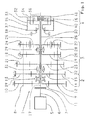
- the Fig. 1 Accordingly, shows a designed as a two-countershaft transmission 1 automated multi-group transmission with two parallel rotatably mounted countershafts 8, 9 and three consecutively arranged transmission groups 2, 3 and 4, as may be provided for example in the drive train of a commercial vehicle.
- a load switching means 16 is arranged for switching an intermediate passage.
- such a transmission in which an intermediate clutch is arranged between an input group and a main group or between a starting clutch and an input group, is per se from the above-mentioned DE 10 2006 024 370 A1 the applicant known.
- a comparable group transmission with an intermediate transmission clutch arranged on the transmission output, but with only one countershaft, is also known from the already mentioned DE 10 2005 046 894 A1 the applicant known.
- the invention therefore relates generally to load switching devices 42, 48, 54 and 59, 61, 63 for assisting the intermediate clutch 16 in a gear change.
- a drive shaft 6 of a drive motor 5 can be connected to a transmission input shaft 17 via a conventional starting element 7 in the form of a friction clutch, for example.
- the first, input-side transmission group 2 is designed as a two-speed splitter gear.
- the second, central transmission group 3 is formed by a three-speed main or basic transmission.
- the splitter gearbox 2 has two gear constants i k1 , i k2 , each of which comprises a fixed wheel 10, 12 or 13, 15 arranged in a rotationally fixed manner on the first countershaft 8 and on the second countershaft 9, which mesh with a loose wheel 11 or 14.
- the first gear constant i k1 faces the starting element 7 and the second gear constant i k2 faces the main gear 3.
- a switching device 39 advantageously with synchronization, arranged over which the idler gears 11 and 14 are selectively rotatably connected to the transmission input shaft 17.
- the main transmission 3 has three forward gear sets i 1 , i 2 and i 3 and a reverse gear i R.
- the first main gear i 1 and the second main gear i 2 each comprise two fixed wheels 18, 20 or 21, 23 and one idler gear 19 and 22, respectively.
- the third main gear i 3 is together with the second gear constant i k2 of the splitter gear 2 realized.
- the reverse gearset i R comprises two fixed wheels 24, 28, a loose wheel 26 and two rotatably mounted intermediate wheels 25, 27 for reversing the direction of rotation, on the one hand with the respective associated fixed gear 24 and 28 and on the other hand with the idler gear 26 mesh.
- the unsynchronized jaw switching device 29 is provided, via which the associated idler gears 19 and 26 selectively rotatably connected to a trained as a hollow shaft main group output shaft 30 can be connected.
- the unsynchronized jaw switching device 31 is further arranged, via which the associated idler gears 22 and 14 are selectively rotatably connected to the main group output shaft 30.
- the gears i 1 , i 2 , i 3 , i R of the main transmission 3 transmit the power flow from the countershafts 8, 9 to the main group output shaft 30 and from there to the transmission output.
- the downstream range transmission 4 is designed as a planetary gear.
- a planetary gear set 32 is guided by a planet carrier 33.
- the planetary gears not explicitly shown mesh on the one hand with a central sun gear 34 and on the other hand with an outer ring gear 35.
- the sun gear 34 is connected to the main group output shaft 30.
- the planet carrier 33 is in turn connected to a transmission output shaft 36.
- a switching device 37 For switching the range gear 4, a switching device 37, advantageously with synchronization, is arranged.
- This switching device 37 connects in a first switching position the ring gear 35 with a housing 38, so that the planet gears between ring gear 35 and sun gear 34 rotate and the transmission output shaft 36, according to a translation of the planetary gear, via the planetary gear 33 in the same direction with the main group output shaft 30 is driven.
- the ring gear 35 is locked to the planet carrier 33, so that the planetary gear 4 and thus the transmission output shaft 36 rotates directly with the speed of the main group output shaft 30.
- a friction clutch intermediate clutch 16 Between the sun gear 34 and the transmission output shaft 36 designed as a friction clutch intermediate clutch 16 is positioned. An inner input part 40 of the intermediate clutch 16 is connected to the end of the extended transmission input shaft 17. An outer, pot-like output part 41 is frontally connected to the planet carrier 33 and thus to the transmission output shaft 36. About conventional input-side and output-side cooperating friction surfaces is a frictional direct connection between the drive, ie transmission input shaft 17 and output, that is, the transmission output shaft 36, produced, the intermediate clutch 16 is controlled via a clutch and transmission control, not shown for a slip operation.
- the shift sequence could also be changed so that even the 10th gear occupies this shift position, so the direct gear is.
- the direct ratio i 1 also corresponds to the intermediate.
- the extended transmission input shaft 17 via the intermediate clutch 16 directly to the transmission output shaft 36 connectable the frictional direct gear, in contrast to the above positive direct gear, via the intermediate clutch 16 in the slip is controllable.
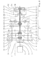
- the Fig. 2 shows a comparable transmission scheme 1 'with a splitter group 2' and a main group 3 ', the power switchable switching means 42, 48, 54 for switching the forward gear sets i 1 , i 2 , i 3 , i instead of the conventional switching devices 29, 31, 39 k1 , i k2 .
- the load switching device 42 of the splitter group 2 ' comprises two coaxial friction clutches 43 and 44, wherein a common outer input part 45 is connected to the transmission input shaft 17.
- the input part 45 engages around an output part 46 connected to the idler gear 11 of the motor-related gear constant i k1 and an opposite output part 47 connected to the idler gear 14 of the motor-independent gear constant i k2 .
- the friction clutches 43 and 44 can be controlled in such a way that switching of the gear constants i k1 , i k2 up to a predetermined Maximum permissible speed difference between the input side and the output side, ie under partial load is possible.
- the load switching device 48 of the main group 3 comprises two coaxial friction clutches 49 and 50, wherein a common outer output part 51 is connected to the main group output shaft 30.
- the output part 51 surrounds a connected to the idler gear 14 of the 3rd main gear i 3 or the gear constants i k2 input part 52 and connected to the idler gear 22 of the 2nd main gear i 2 opposite input part 53.
- This load switching device 48 allows switching operations of the assigned wheelsets i 2 and i 3 under partial load.
- the first main gear i 1 is associated with a third load switching device 54.
- This load switching device 54 comprises a friction clutch 55, wherein an outer output part 56 is connected to the main group output shaft 30 and an inner input part 57 with the idler gear 19 of the gear i 1 .
- a conventional claw switching device 58 is provided for the reverse gear i R.
- FIG. 3 Another transmission diagram 1 "shows Fig. 3 , Therein are arranged in a splitter group 2 "and in a main group 3" load switching devices 59, 61, 63 with unspecified power shift claws 60, 62, 64.
- the two first Lastschaltklauen 60, 62 are alternately effective on two sides, each with a load switching claw 60, 62 in a similar manner, the functions of two friction clutches 43, 44 and 49, 50 from Fig. 2 Fulfills.
- the load shift claw 64 is also on both sides load switchable. However, this load shift claw 64 may also be formed on the reverse gear side i R as a simple shift claw.
- An inventive method for operating a multi-group transmission is based essentially on the fact that in a gear change to Switzerlandkrafterigen with closed start-up element 7 via an intermediate clutch 16, an intermediate passage is switched, with the aid of load or partial load switchable switching devices 42, 48, 54 and 59, 61, 63 on the wheelsets i 1 , i 2 , i 3 , i k1 , i k2 reduced switching times are achieved and thus the gear change is shortened in time.
- the intermediate clutch 16 of the intermediate gear When initiated by the driver or a transmission control shift request is connected via the intermediate clutch 16 of the intermediate gear, ie a direct connection between the transmission input shaft 17 and the transmission output shaft 36 made. While the engine speed in slip mode of the intermediate clutch 16 approximates the requested target gear, the gearshift change can be carried out even before a complete rotational speed equality of the corresponding shafts is reached, ie the main gearbox 3 ', 3 "is displaced as a result of the support of the engine torque. ie the original gear is released and the target gear is engaged via the corresponding load shifting devices 42, 48, 54 or 59, 61, 63.
- the starting element 7 remains closed during the entire shifting process Gear jump, the traction-assisted gear change alternatively or additionally include switching the gear constants i k1 , i k2 of the splitter gear 2 ', 2 ", also with power shift support, and / or a gear range switching of the range gear 4.
Landscapes
- Engineering & Computer Science (AREA)
- General Engineering & Computer Science (AREA)
- Mechanical Engineering (AREA)
- Structure Of Transmissions (AREA)
Applications Claiming Priority (1)
| Application Number | Priority Date | Filing Date | Title |
|---|---|---|---|
| DE102008002750A DE102008002750A1 (de) | 2008-06-30 | 2008-06-30 | Mehrgruppengetriebe eines Kraftfahrzeuges |
Publications (1)
| Publication Number | Publication Date |
|---|---|
| EP2141386A1 true EP2141386A1 (fr) | 2010-01-06 |
Family
ID=41120034
Family Applications (1)
| Application Number | Title | Priority Date | Filing Date |
|---|---|---|---|
| EP09159730A Withdrawn EP2141386A1 (fr) | 2008-06-30 | 2009-05-08 | Boîte de vitesse à plusieurs groupes d'un véhicule automobile |
Country Status (3)
| Country | Link |
|---|---|
| US (1) | US20090325763A1 (fr) |
| EP (1) | EP2141386A1 (fr) |
| DE (1) | DE102008002750A1 (fr) |
Cited By (2)
| Publication number | Priority date | Publication date | Assignee | Title |
|---|---|---|---|---|
| CN102207173A (zh) * | 2010-03-31 | 2011-10-05 | 通用汽车环球科技运作有限责任公司 | 八速行星齿轮副轴变速器 |
| WO2012062654A1 (fr) * | 2010-11-10 | 2012-05-18 | Ford Global Technologies, Llc | Transmission à plusieurs rapports |
Families Citing this family (7)
| Publication number | Priority date | Publication date | Assignee | Title |
|---|---|---|---|---|
| DE102010041303A1 (de) * | 2010-09-24 | 2012-03-29 | Zf Friedrichshafen Ag | Verfahren zur Kennlinienadaption von Kupplungen in einem Teildoppelkupplungsgetriebe eines Fahrzeugs |
| DE102010042656B4 (de) * | 2010-10-20 | 2022-06-23 | Zf Friedrichshafen Ag | Lastschaltbares Getriebe |
| DE102011076391A1 (de) * | 2011-05-24 | 2012-11-29 | Zf Friedrichshafen Ag | Parallelschaltgetriebe |
| DE102012213667A1 (de) * | 2012-08-02 | 2014-02-06 | Zf Friedrichshafen Ag | Übersetzungsstufe eines Stufengetriebes, sowie Stufengetriebe |
| US10393230B2 (en) | 2016-08-03 | 2019-08-27 | Cnh Industrial America Llc | Transmission system for a work vehicle |
| DE102016223016A1 (de) * | 2016-11-22 | 2018-05-24 | Zf Friedrichshafen Ag | Verfahren zur Schaltsteuerung eines automatisierten Gruppengetriebes |
| DE102018217829A1 (de) * | 2018-10-18 | 2020-04-23 | Zf Friedrichshafen Ag | Getriebe und Antriebssystem eines Kraftfahrzeugs |
Citations (6)
| Publication number | Priority date | Publication date | Assignee | Title |
|---|---|---|---|---|
| US3542176A (en) * | 1968-10-28 | 1970-11-24 | Ford Motor Co | Multiple range power transmission mechanism |
| DE1950914A1 (de) * | 1969-10-09 | 1971-04-22 | Kloeckner Humboldt Deutz Ag | Verfahren und Einrichtung zum Schalten eines mehrstufigen Zahnradwechselgetriebes |
| EP1293695A2 (fr) * | 2001-09-13 | 2003-03-19 | GETRAG Getriebe- und Zahnradfabrik Hermann Hagenmeyer GmbH & Cie KG | Embrayage à liason positive et transmission robotisée |
| WO2006123166A2 (fr) * | 2005-05-18 | 2006-11-23 | Zeroshift Limited | Agencement de transmission |
| DE102005046894A1 (de) | 2005-09-30 | 2007-05-03 | Zf Friedrichshafen Ag | Automatisiertes Kfz-Schaltgetriebe und Verfahren zur Schaltsteuerung eines automatisierten Kfz-Schaltgetriebes |
| DE102006024370A1 (de) | 2006-05-24 | 2007-12-13 | Zf Friedrichshafen Ag | Mehrgruppengetriebe und Verfahren zum Gangwechsel bei einem Mehrgruppengetriebe |
Family Cites Families (1)
| Publication number | Priority date | Publication date | Assignee | Title |
|---|---|---|---|---|
| US7470206B2 (en) * | 2006-07-24 | 2008-12-30 | General Motors Corporation | Multi-speed countershaft transmission with a planetary gear set |
-
2008
- 2008-06-30 DE DE102008002750A patent/DE102008002750A1/de not_active Withdrawn
-
2009
- 2009-05-08 EP EP09159730A patent/EP2141386A1/fr not_active Withdrawn
- 2009-06-24 US US12/490,499 patent/US20090325763A1/en not_active Abandoned
Patent Citations (6)
| Publication number | Priority date | Publication date | Assignee | Title |
|---|---|---|---|---|
| US3542176A (en) * | 1968-10-28 | 1970-11-24 | Ford Motor Co | Multiple range power transmission mechanism |
| DE1950914A1 (de) * | 1969-10-09 | 1971-04-22 | Kloeckner Humboldt Deutz Ag | Verfahren und Einrichtung zum Schalten eines mehrstufigen Zahnradwechselgetriebes |
| EP1293695A2 (fr) * | 2001-09-13 | 2003-03-19 | GETRAG Getriebe- und Zahnradfabrik Hermann Hagenmeyer GmbH & Cie KG | Embrayage à liason positive et transmission robotisée |
| WO2006123166A2 (fr) * | 2005-05-18 | 2006-11-23 | Zeroshift Limited | Agencement de transmission |
| DE102005046894A1 (de) | 2005-09-30 | 2007-05-03 | Zf Friedrichshafen Ag | Automatisiertes Kfz-Schaltgetriebe und Verfahren zur Schaltsteuerung eines automatisierten Kfz-Schaltgetriebes |
| DE102006024370A1 (de) | 2006-05-24 | 2007-12-13 | Zf Friedrichshafen Ag | Mehrgruppengetriebe und Verfahren zum Gangwechsel bei einem Mehrgruppengetriebe |
Cited By (4)
| Publication number | Priority date | Publication date | Assignee | Title |
|---|---|---|---|---|
| CN102207173A (zh) * | 2010-03-31 | 2011-10-05 | 通用汽车环球科技运作有限责任公司 | 八速行星齿轮副轴变速器 |
| CN102207173B (zh) * | 2010-03-31 | 2014-04-02 | 通用汽车环球科技运作有限责任公司 | 八速行星齿轮副轴变速器 |
| WO2012062654A1 (fr) * | 2010-11-10 | 2012-05-18 | Ford Global Technologies, Llc | Transmission à plusieurs rapports |
| US20130217534A1 (en) * | 2010-11-10 | 2013-08-22 | Ford Global Technologies, Llc | Multispeed transmission |
Also Published As
| Publication number | Publication date |
|---|---|
| DE102008002750A1 (de) | 2009-12-31 |
| US20090325763A1 (en) | 2009-12-31 |
Similar Documents
| Publication | Publication Date | Title |
|---|---|---|
| EP2356352B1 (fr) | Boîte de vitesses automatisée multigroupe pour véhicule à moteur et procédé de fonctionnement d'une boîte de vitesses automatisée multigroupe | |
| EP2128495B1 (fr) | Boîte de vitesse à plusieurs groupes d'un véhicule automobile | |
| EP2133592B1 (fr) | Boîte de vitesse à plusieurs groupes d'un véhicule automobile | |
| EP2019939B1 (fr) | Boîte de vitesses à plusieurs groupes et procédé pour changer de vitesses avec une boîte de vitesses à plusieurs groupes | |
| EP2123941B1 (fr) | Boîte de vitesse à plusieurs groupes d'un véhicule automobile | |
| EP1728006B1 (fr) | Transmission planetaire, en particulier transmission planetaire a embrayage double | |
| EP2110581A2 (fr) | Boîte de vitesse à plusieurs groupes d'un véhicule automobile | |
| EP2118527B1 (fr) | Procédé destiné à faire fonctionner la chaîne cinématique d'un véhicule | |
| EP2141386A1 (fr) | Boîte de vitesse à plusieurs groupes d'un véhicule automobile | |
| WO2009149993A1 (fr) | Boîte de vitesses multigroupe d’un véhicule à moteur | |
| DE102005050067A1 (de) | Automatisiertes Schaltgetriebe und Verfahren zur Schaltsteuerung eines solchen Schaltgetriebes | |
| WO2006056325A2 (fr) | Mecanisme de changement de vitesse a variation discontinue pour automobile | |
| WO2009127473A1 (fr) | Transmission à groupes multiples pour véhicule automobile | |
| DE19924501A1 (de) | Lastschaltbares Stufenwechselgetriebe | |
| EP2113686A2 (fr) | Boîte de vitesse à plusieurs groupes d'un véhicule automobile | |
| EP3303880A1 (fr) | Groupe-relais pour un véhicule à moteur et procédé pour faire fonctionner un groupe-relais de ce type | |
| WO2015149823A1 (fr) | Boîte de changement de vitesse pour un véhicule automobile | |
| AT512917B1 (de) | Verfahren zum Betreiben eines Doppelkupplungsgetriebes | |
| EP3669100B1 (fr) | Dispositif de train d'engrenages | |
| DE10347273B4 (de) | Parallelstranggetriebe für ein Kraftfahrzeug und Verfahren zum Betreiben | |
| EP1028270B1 (fr) | Train d'entraínement automatisable pour véhicule | |
| DE102019216464A1 (de) | Automatisches Schaltgetriebe für Kraftfahrzeuge | |
| EP2123940A1 (fr) | Boîte de vitesse à plusieurs groupes d'un véhicule automobile | |
| DE102008001689A1 (de) | Mehrgruppengetriebe eines Kraftfahrzeuges | |
| DE10149173A1 (de) | Verbindungsglied (Kupplungselement)zur torsionsmomentenunterbrechungsfreien Übersetzungsumschaltung in Getrieben |
Legal Events
| Date | Code | Title | Description |
|---|---|---|---|
| PUAI | Public reference made under article 153(3) epc to a published international application that has entered the european phase |
Free format text: ORIGINAL CODE: 0009012 |
|
| AK | Designated contracting states |
Kind code of ref document: A1 Designated state(s): AT BE BG CH CY CZ DE DK EE ES FI FR GB GR HR HU IE IS IT LI LT LU LV MC MK MT NL NO PL PT RO SE SI SK TR |
|
| 17P | Request for examination filed |
Effective date: 20100702 |
|
| 17Q | First examination report despatched |
Effective date: 20100726 |
|
| STAA | Information on the status of an ep patent application or granted ep patent |
Free format text: STATUS: THE APPLICATION IS DEEMED TO BE WITHDRAWN |
|
| 18D | Application deemed to be withdrawn |
Effective date: 20110817 |