EP2834413B1 - Rail fastening element for a fixed slab track - Google Patents
Rail fastening element for a fixed slab track Download PDFInfo
- Publication number
- EP2834413B1 EP2834413B1 EP13726273.9A EP13726273A EP2834413B1 EP 2834413 B1 EP2834413 B1 EP 2834413B1 EP 13726273 A EP13726273 A EP 13726273A EP 2834413 B1 EP2834413 B1 EP 2834413B1
- Authority
- EP
- European Patent Office
- Prior art keywords
- rail
- cut
- outs
- track
- elements
- Prior art date
- Legal status (The legal status is an assumption and is not a legal conclusion. Google has not performed a legal analysis and makes no representation as to the accuracy of the status listed.)
- Active
Links
Images

Classifications
-
- E—FIXED CONSTRUCTIONS
- E01—CONSTRUCTION OF ROADS, RAILWAYS, OR BRIDGES
- E01B—PERMANENT WAY; PERMANENT-WAY TOOLS; MACHINES FOR MAKING RAILWAYS OF ALL KINDS
- E01B1/00—Ballastway; Other means for supporting the sleepers or the track; Drainage of the ballastway
- E01B1/002—Ballastless track, e.g. concrete slab trackway, or with asphalt layers
-
- E—FIXED CONSTRUCTIONS
- E01—CONSTRUCTION OF ROADS, RAILWAYS, OR BRIDGES
- E01B—PERMANENT WAY; PERMANENT-WAY TOOLS; MACHINES FOR MAKING RAILWAYS OF ALL KINDS
- E01B2/00—General structure of permanent way
- E01B2/003—Arrangement of tracks on bridges or in tunnels
-
- E—FIXED CONSTRUCTIONS
- E01—CONSTRUCTION OF ROADS, RAILWAYS, OR BRIDGES
- E01B—PERMANENT WAY; PERMANENT-WAY TOOLS; MACHINES FOR MAKING RAILWAYS OF ALL KINDS
- E01B9/00—Fastening rails on sleepers, or the like
- E01B9/02—Fastening rails, tie-plates, or chairs directly on sleepers or foundations; Means therefor
- E01B9/28—Fastening on wooden or concrete sleepers or on masonry with clamp members
Definitions
- the invention relates to a rail fastening element for rails of a fixed slab track according to the preamble of claim 1 and, furthermore, is directed to a fixed slab track for rail vehicles according to the preamble of claim 5, comprising the rail fastening element of the type according to the invention.
- the track After the underfilling of the sleeper framework, the track cannot be driven along or can only be driven along to a restricted extent for a comparatively long time, because the construction materials which are used for underfilling, as a rule concrete, partly require several days, in order to achieve sufficient strength to allow the track to be driven along.
- the principle is therefore preferably used, in particular, where supplying material from the sides is not possible, for example via the neighbouring track.
- the disadvantage of this method of construction is that it is comparatively imprecise and that a subsequent positional and, above all, vertical adaptation of the running rails to the rail fastening elements therefore has to be performed in most cases despite great efforts and production accuracy.
- These adaptations are not only complicated, but lead to the possibilities of subsequent adjustment of the track position, which are required by the constructor for the later operating phase, already having to be utilized during the initial adjustment and then later not being available or no longer being available to the required extent.
- a rail fastening element comprising a mounting base body and a rail holder which interacts with the mounting base body on the upper side thereof.
- the monting base body has bores which constitute receptacles for fastening bolts which are palced in studholes provided in a supporting layer underneath the mounting base body. Synthetic resin is filled inbetween the lower parts of the bolts and the surrounding stud holes.
- EP 0 676 504 A1 discloses a similar fixed slab track for rail vehicles having a base layer formed by an underlying substrate, and a plurality of support elements mounted theron, which are secured in their position on the substarte by means of fastening elementswhich are secured in cut-outs in the substrate by means of a pourable concrete which is pured underneath the support elements.
- DE 44 15 363 C discloses a rail fastening element for a fixed slab track according to the preamble of claim 1.
- this object is achieved by a rail fastening element for a fixed slab track for rail vehicles according to independent claim 1 and a fixed slab track comprising such rail fastening element according to claim 5.
- the combination according to the invention combines in a particularly advantageous way the installation principles firstly of bottom-up and secondly of top-down, by the base layer first of all being set up on the rail track substrate in the bottom-up construction principle, which base layer can preferably be an asphalt layer or else a hydraulically bound support layer.
- the support elements are mounted next to one another or behind one another on the said base layer, likewise in the bottom-up construction principle, it being possible for both working steps to be carried out with comparatively large tolerances.
- the main requirement of the base layer namely consists principally in ensuring the required load-bearing capability for the track, which is achieved by the asphalt or concrete which is preferably introduced for the base layer, without the layer being set up in a millimetre-precise manner.
- the support elements which are mounted on the base layer also do not have to be produced with the very highest dimensional accuracy, but principally have to have a required strength, to which end they can be produced as prefabricated components under consideration of the required material qualities, but actually with comparatively large tolerances with regard to their dimensions.
- the lower base layer and the support elements which are placed onto it can have a positional and vertical accuracy with comparatively large tolerances which lie in the centimetre range
- the required high final accuracy is not achieved until the end of the works to be carried out, after all rough work has been ended, with comparatively low effort, by the rail fastening elements namely then being inserted according to the construction principle from the top to the bottom into the cut-outs in the support elements, being oriented in the desired vertical and lateral position and then being fixed in this position, by a hardening sealing compound being introduced below and/or around the rail fastening elements and into the cut-outs.
- the quantity of the sealing compound to be used is also considerably less than in cases, in which an entire sleeper framework comprising rails and sleepers is underpoured completely with site-mixed concrete, as is regularly the case in known "top-down" construction methods.
- the comparatively low quantity of sealing compound which is used it is economically justifiable to also use expensive materials for this purpose which can have the advantage of higher strengths and more rapid hardening in comparison with conventional site-mixed concrete.
- At least part of the support elements is formed by sleeper-like transverse support elements which are oriented transversely with respect to the longitudinal direction of the rail track and are provided on their upper side with cut-outs which are intended in pairs for rail fastening elements of a right-hand and a left-hand rail of the track.
- at least part of the support elements is formed by longitudinal support elements which are oriented in the longitudinal direction of the rail track and are arranged below a right-hand or a left-hand rail of the track, each of the longitudinal support elements having a plurality of cut-outs for rail fastening elements for fastening the left-hand or the right-hand rail. Both transverse support elements and longitudinal support elements will frequently be used as support elements for a fixed slab track according to the invention.
- the rail fastening elements have a mounting base body which is arranged or can be arranged in the cut-outs or above the latter and at least one rail holder which interacts with the said mounting base body on the base-body upper side in a positively locking manner.
- the mounting base body is provided with at least one filling channel which penetrates it substantially vertically, the sealing compound can be filled through the said filling channel and, as a result, can be filled particularly reliably into the intermediate space between the mounting base body and the support element which lies below it or the cut-out which is provided in it, whereby it becomes possible to limit the quantity of sealing compound which is used to a minimum.
- the mounting base body can be provided with reinforcing ribs which, between themselves, delimit at least one chamber which can be filled from below at least partially with sealing compound, the ribs preferably being enclosed on all sides by the sealing compound after hardening of the latter, and a particularly firm connection between the mounting base body and the support element which lies below it being ensured as a result.
- the mounting base body On the base-body upper side, the mounting base body has a holder guide which receives the rail holder or holders in a positively locking manner, preferably transversely with respect to the rail longitudinal direction, which holder guide ensures that the transverse forces which act on the rails which are fastened to the rail fastening elements are dissipated reliably into the mounting base body and, from the latter, into the support elements and the further track substructure.
- the rail fastening elements are provided with downwardly projecting anchor elements which engage into the cut-outs from above.
- the arrangement is preferably provided in such a way that the anchor elements are formed substantially by anchor sleeves for sleeper bolts which penetrate the rail holders and mounting base body.
- connection reinforcements which are provided in the cut-outs serve for a further increase in the strength of the connection between the support elements and the rail fastening elements, which connection reinforcements are enclosed by the sealing compound after the track is finished.
- the cut-outs are divided into a plurality of, preferably two chambers, with the result that the entire volume to be filled can be limited to a minimum quantity.
- the latter can be provided with pouring bevels on at least one edge side.
- a holder guide is formed on the base-body upper side of the mounting base body and receives the rail holder or holders in a positively locking manner transversely with respect to the rail longitudinal direction. It preferably tapers in a downward direction in one preferred refinement and is delimited laterally by oblique guide faces, whereas the rail holder or holders is/are provided with corresponding oblique faces, the inclination of which is adapted to the guide faces. This achieves a self-centring action of the rail holders during their mounting on the holder guide when the rail holders are tightened by means of the sleeper bolts or the like in order to fasten the rail.
- the holder guide can have at least one guide groove which is formed on the base-body upper side, runs in the rail longitudinal direction, and into which an adapted guide projection which is formed on the rail holder engages in a positively locking manner.
- Each of the rail fastening elements can preferably have two rail holders which, between themselves, leave a receptacle exposed for the rail foot of the rail and optionally for setting and/or compensating plates which are to be arranged below the rail foot on the base-body upper side.
- a method for setting up a track in a fixed slab track is shown, according to the method first of all a base layer being provided which is preferably arranged as an asphalt layer on an underlying substrate or is formed by the underlying substrate which is configured, for example, as a hydraulically bound support layer.
- a multiplicity of support elements which have in each case at least one cut-out on their upper side are mounted on the base layer.
- the said support elements which can be configured as sleeper-like transverse support elements which are oriented transversely with respect to the longitudinal direction of the rail track or else as longitudinal support elements which are oriented in the longitudinal direction of the rail track and are arranged below a right-hand or left-hand rail of the track are preferably prefabricated components, the dimensional tolerances of which do not have to be subjected to any particularly high requirements.
- a sleeper framework which can comprise the two running rails, (possibly temporary) gauge tie bars which connect them to one another and rail fastening elements which are connected to the rails can then be oriented in its vertical and lateral position on the said track substructure which is therefore set up from the bottom to the top (bottom-up), in such a way that the rail fastening elements are situated above the cut-outs in the support elements and engage at least partially from above into the latter.
- the rail fastening elements are locked by introduction of a hardening sealing compound into the intermediate spaces which remain between the rail fastening elements and the support elements and into the cut-outs.
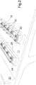
- Fig. 1 shows a perspective illustration of a section of a fixed slab track for rail vehicles which is denoted in its entirety by 10, as can also be used, in particular, for high-speed lines.
- the rail track 10 has a base layer 12 which is arranged on an underlying substrate 11, which can be, for example, a hydraulically bound support layer, and is produced as an asphalt surface which is manufactured without joints in the preferred exemplary embodiment which is shown.
- this is an asphalt support layer (B70/100) which is approximately 15 cm thick and 270 cm wide, is applied on the underlying substrate 11 by way of a conventional asphalt road finishing machine according to the bottom-up construction principle, and is rolled if required in order to achieve an increased strength.
- a multiplicity of support elements 13 are mounted on the asphalt base layer 12 which can already be loaded a few hours after it is installed.
- the said support elements 13 comprise transverse support elements 15 which are oriented transversely with respect to the longitudinal direction 14 of the rail track 10, are of sleeper-like design and are produced as concrete prefabricated parts.
- the said concrete prefabricated parts can also be produced with comparatively large tolerances, for example can be produced vertically with ⁇ 6 mm, as long as they meet the requirements made of them with regard to their concrete quality/strength.
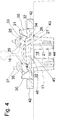
- Each of the transverse support elements is provided with two cut-outs 17 ( Fig. 4 ) which are arranged in pairs on the left and right in the region below the rails 16, each of the cut-outs 17 having two chambers 19 which are separated by a dividing wall 18.
- Rail fastening elements for the rails 16 are situated above the cut-outs 17, which rail fastening elements are denoted in their entirety by 20, are inserted from above with downwardly projecting anchor elements 21 into the chambers 19 of the cut-outs 17, and are locked on the support elements 13, as will still be described in the following text, by means of a hardening sealing compound 22.
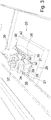
- the second embodiment (shown in Fig. 2 ) of the fixed slab track according to the invention differs from the first embodiment initially in the fact that the underlying substrate 11 is formed by an artificial edifice, in the present case a reinforced concrete bridge 23.
- the transverse support elements 15 in the first embodiment are laid in a more or less floating manner, longitudinal support elements 24 which are connected fixedly by means of underpoured site-mixed concrete 25 to the underlying substrate 11 which is formed by the reinforced concrete bridge 23 are used in the second embodiment.
- each of the longitudinal support elements 24 has three cut-outs 17 for rail fastening elements 20 which are arranged one behind another in the longitudinal direction 14 of the rails 16 and in each case serve to fasten one of the two rails.
- the rail fastening elements 20 in each case have a mounting base body 26 which is arranged above the cut-outs 17 and from which the anchor elements 21 project downwards and engage into the two chambers 19 of the associated cut-out 17.
- a holder guide 28 which serves to interact in a positively locking manner with two rail holders 29 of the rail fastening element 20 and to fix the latter transversely with respect to the rail longitudinal direction 14.
- the holder guide 28 has two upwardly projecting guide flanges 30 with downwardly converging, oblique guide faces 31 which taper into guide grooves 32 which are formed on the base-body upper side 27 and run in the rail longitudinal direction 14.
- the rail holders 29 are provided with corresponding oblique faces 13, the inclination of which is adapted to the guide faces 31, and, on their underside, have a guide projection 34, with which they engage in each case into one of the guide grooves 32.
- the rails 16 are fixed on the rail fastening elements 20 in a substantially known way by means of holding clips 35 which engage over the rail foot 36 and are pressed by sleeper bolts 37 against the rail foot 36 and the rail holders 29, which sleeper bolts 37 penetrate the rail fastening elements 20 and are screwed into the anchor sleeves 21 which project below the rail fastening elements 20 into the cut-outs 17 in the support elements 13.
- Filling channels 38 which penetrate the mounting base bodies 26 vertically from top to bottom are provided in the guide flanges 30 of the said mounting base bodies 26, through which filling channels 38 the sealing compound 22 can be filled for underfilling the fastening elements and for locking purposes, as is indicated by the arrow 39 in Fig. 3 , after the orientation of the rail fastening elements or the rail, to which the former are attached.
- the mounting base body 26 On its underside, the mounting base body 26 is provided with a plurality of anchor ribs 40 which, after the underfilling of the base body with the sealing compound 22, are enclosed completely by the latter, with the result that the anchor ribs 40 lock the mounting base body in the hardened sealing compound in a positively locking manner transversely with respect to the rail longitudinal direction.
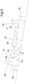
- the mounting base body 26 has, on the underside, a ribbed structure 41 which can be seen satisfactorily in the sectional illustration in Fig. 5 and which is likewise enclosed partially by sealing compound.
- connection reinforcements 44 which project from the bottom to the top and give the filled sealing compound even higher strength are provided in the chambers of the cut-outs 17.
- the rail fastening elements 20 are not oriented individually in each case on their own before pouring, but rather for this purpose are connected to the sleeper framework which is formed by the rails 16 and gauge tie rods (not shown), as is known. Readjustment of the rail position even after hardening of the sealing compound, for example after relatively long travel operation, is possible without problems by way of the exchange of setting or compensating plates 46 which can be arranged between the two rail holders 29 below the rail foot 36 on the base-body upper side 27, as can be seen best in Fig. 4 .
- the transverse forces which are exerted on the rails by the rail vehicles during travel operation and occur transversely with respect to the longitudinal direction 14 of the rails are dissipated by the rail holders which are guided in a positively locking manner in the holder guide 28 into the base body 26 and from the latter via the downwardly projecting anchor ribs 40 and the hardened sealing compound 22 which encloses them uniformly over the entire underpoured foundation.
- the anchor elements 21 which project deeply into the transverse support elements and are poured at the same time in the cut-outs ensure that the sleeper bolts 27 can be loaded with high tightening strengths and therefore fix the rails reliably and permanently to the rail fastening elements.
Landscapes
- Engineering & Computer Science (AREA)
- Architecture (AREA)
- Civil Engineering (AREA)
- Structural Engineering (AREA)
- Mechanical Engineering (AREA)
- Machines For Laying And Maintaining Railways (AREA)
- Railway Tracks (AREA)
Priority Applications (1)
| Application Number | Priority Date | Filing Date | Title |
|---|---|---|---|
| PL13726273T PL2834413T3 (pl) | 2012-04-05 | 2013-04-04 | Element mocujący szynę dla stałych torów bezpodsypkowych |
Applications Claiming Priority (2)
| Application Number | Priority Date | Filing Date | Title |
|---|---|---|---|
| DE102012103001A DE102012103001A1 (de) | 2012-04-05 | 2012-04-05 | Feste Fahrbahn für Schienenfahrzeuge sowie Schienenbefestigungselement für eine feste Fahrbahn |
| PCT/IB2013/052705 WO2013150482A1 (en) | 2012-04-05 | 2013-04-04 | Fixed slab track for rail vehicles, and rail fastening element therefore |
Publications (2)
| Publication Number | Publication Date |
|---|---|
| EP2834413A1 EP2834413A1 (en) | 2015-02-11 |
| EP2834413B1 true EP2834413B1 (en) | 2020-10-14 |
Family
ID=48539308
Family Applications (1)
| Application Number | Title | Priority Date | Filing Date |
|---|---|---|---|
| EP13726273.9A Active EP2834413B1 (en) | 2012-04-05 | 2013-04-04 | Rail fastening element for a fixed slab track |
Country Status (6)
| Country | Link |
|---|---|
| EP (1) | EP2834413B1 (pl) |
| DE (1) | DE102012103001A1 (pl) |
| DK (1) | DK2834413T3 (pl) |
| ES (1) | ES2841068T3 (pl) |
| PL (1) | PL2834413T3 (pl) |
| WO (1) | WO2013150482A1 (pl) |
Families Citing this family (3)
| Publication number | Priority date | Publication date | Assignee | Title |
|---|---|---|---|---|
| WO2014037838A1 (en) | 2012-09-04 | 2014-03-13 | Rte Technologie Gmbh | Locating pin arrangement for aligning railway slabs on a base plate |
| CN114808557B (zh) * | 2022-03-22 | 2023-09-01 | 上海市城市建设设计研究总院(集团)有限公司 | 有轨电车防迷流钢筋网的固定结构及施工方法 |
| WO2026062168A1 (de) * | 2024-09-20 | 2026-03-26 | Voestalpine Railway Systems GmbH | Schalungselement zur herstellung eines schienenstützkörpers |
Citations (1)
| Publication number | Priority date | Publication date | Assignee | Title |
|---|---|---|---|---|
| DE4415363C1 (de) * | 1994-05-02 | 1995-09-28 | Walter Bau Ag | Eine feste Fahrbahn bildender Oberbau für Schienenbahnen, insb. für Brücken und Verfahren zu seiner Herstellung |
Family Cites Families (15)
| Publication number | Priority date | Publication date | Assignee | Title |
|---|---|---|---|---|
| DE2659161A1 (de) * | 1976-12-28 | 1978-07-06 | Zueblin Ag | Schotterloser eisenbahnoberbau |
| US4616395A (en) * | 1983-06-30 | 1986-10-14 | Perini Corporation | Railroad track fixation method and apparatus |
| DE4411889A1 (de) * | 1994-04-07 | 1995-10-12 | Hochtief Ag Hoch Tiefbauten | Schotterloses Oberbausystem für zumindest ein Eisenbahngleis und Verfahren zur Herstellung |
| DE4419877C1 (de) * | 1994-06-07 | 1995-11-02 | Zueblin Ag | Schwellenlose Oberbaukonstruktion für Schienenbahnen, insb. für Brücken |
| DE19517112A1 (de) * | 1994-12-22 | 1996-07-04 | Heilit & Woerner Bau Ag | Gleisoberbau mit durchgehender Tragplatte und Einzel-Befestigungsvorrichtungen für die Schienen |
| DE19620731A1 (de) * | 1996-05-23 | 1997-11-27 | Strabag Hoch Und Ingenieurbau | Feste Fahrbahn für schienengebundene Fahrzeuge auf Brücken und Verfahren zu ihrer Herstellung |
| DE19824395C1 (de) * | 1998-05-30 | 1999-07-22 | Hochtief Ag Hoch Tiefbauten | Verfahren zum Herstellen eines schotterlosen Oberbausystems für zumindest ein Eisenbahngleis aus zwei Eisenbahnschienen, insbesondere für Hochgeschwindigkeitsstrecken und dabei verwendbare Vorrichtung |
| DE19944783A1 (de) * | 1999-02-08 | 2000-08-10 | Hochtief Ag Hoch Tiefbauten | Feste-Fahrbahn-System |
| DE29902595U1 (de) * | 1999-02-13 | 1999-04-29 | Friedrich Hagans, Plastverarbeitung, 99099 Erfurt | Schwingungsdämpfende Zwischenlage für Schienenunterstützung auf festem Unterbau |
| DE19919506A1 (de) * | 1999-04-29 | 2000-11-30 | Thyssen Krupp Materials & Serv | Federnde Schienenbefestigung |
| DE19932991A1 (de) * | 1999-07-14 | 2000-06-21 | Friedrich Hagans Plastverarbei | Schwingungsdämpfende Einzelstütze aus elastischem Kunststoff |
| DE10248037B3 (de) * | 2002-10-15 | 2004-05-06 | Walter - Heilit Verkehrswegebau Gmbh | Verfahren zur Nachbehandlung einer Schienenfahrbahn |
| DE10328895A1 (de) * | 2003-06-26 | 2005-01-20 | Rte Technologie Gmbh | Verfahren zum Herstellen einer Gleisfahrbahn für Schienenfahrzeuge |
| PL1709249T3 (pl) * | 2004-01-29 | 2014-03-31 | Wirthwein Ag | Punkt podparcia szyny o wysokiej sprężystości i izolacji elektrycznej |
| AT12185U1 (de) * | 2010-08-09 | 2011-12-15 | Naumov Boris Vladimilenovich | Unterschienenstütze und oberbau eines schienengleises |
-
2012
- 2012-04-05 DE DE102012103001A patent/DE102012103001A1/de not_active Withdrawn
-
2013
- 2013-04-04 PL PL13726273T patent/PL2834413T3/pl unknown
- 2013-04-04 EP EP13726273.9A patent/EP2834413B1/en active Active
- 2013-04-04 DK DK13726273.9T patent/DK2834413T3/da active
- 2013-04-04 ES ES13726273T patent/ES2841068T3/es active Active
- 2013-04-04 WO PCT/IB2013/052705 patent/WO2013150482A1/en not_active Ceased
Patent Citations (1)
| Publication number | Priority date | Publication date | Assignee | Title |
|---|---|---|---|---|
| DE4415363C1 (de) * | 1994-05-02 | 1995-09-28 | Walter Bau Ag | Eine feste Fahrbahn bildender Oberbau für Schienenbahnen, insb. für Brücken und Verfahren zu seiner Herstellung |
Also Published As
| Publication number | Publication date |
|---|---|
| WO2013150482A1 (en) | 2013-10-10 |
| PL2834413T3 (pl) | 2021-05-17 |
| DK2834413T3 (da) | 2021-01-04 |
| ES2841068T3 (es) | 2021-07-07 |
| EP2834413A1 (en) | 2015-02-11 |
| DE102012103001A1 (de) | 2013-10-10 |
Similar Documents
| Publication | Publication Date | Title |
|---|---|---|
| US9157192B2 (en) | Method for producing a slab trackway | |
| RU2148685C1 (ru) | Способ изготовления системы верхнего строения пути без щебеночного балласта (варианты) | |
| CZ295073B6 (cs) | Železobetonový panel, jeho použití k výrobě deskové spřažené konstrukce a postup výroby konstrukce z těchto panelů | |
| CA2279638C (en) | Method for installing a steady rail track | |
| HUP0401337A2 (en) | Method for the continuous laying of a rail on a rigid track, in addition to an alignment device and a rigid track | |
| ZA200705820B (en) | Concrete track for rail vehicles | |
| PL212892B1 (pl) | Sposób budowania toru szynowego na podkladowej plycie betonowej | |
| KR20190055392A (ko) | 궤도지지말뚝용 프리캐스트 거푸집 및 이를 이용한 콘크리트 궤도시공방법 | |
| RU2377361C2 (ru) | Твердое дорожное полотно для рельсовых транспортных средств | |
| WO2013150482A1 (en) | Fixed slab track for rail vehicles, and rail fastening element therefore | |
| CN1296560C (zh) | 用于铁路运输的固定轨道及其制造方法 | |
| DE4007710A1 (de) | Verfahren zum herstellen eines eisenbahnoberbaus im tunnel | |
| WO2017187461A1 (en) | Slab track, arranged in an overlapping manner on a slab foundation | |
| ES2258804T3 (es) | Procedimiento para la construccion de una bancada de via fija para trafico guiado sobre railes, asi como una bancada de via fija para llevar a cabo el procedimiento. | |
| HU210631B (en) | Railway body | |
| PL213301B1 (pl) | Sposób modernizacji nawierzchni kolejowej dla utworzenia stalej nawierzchni kolejowej duzych predkosci oraz stala nawierzchnia kolejowa duzych predkosci, utworzona ze zmodernizowanej nawierzchni kolejowej | |
| EP1216326B1 (de) | Verfahren zur herstellung eines schallgedämmten gleises | |
| JP7712225B2 (ja) | 防護柵、防護柵の設置方法及び床版の架け替え工法 | |
| JP7772991B1 (ja) | 鋼製枠を用いた床版設置工法及びコンクリート床版の補強構造 | |
| AT413551B (de) | Verfahren zum herstellen einer festen fahrbahn für schienenfahrzeuge | |
| JP3791719B2 (ja) | 工事桁を利用した直結軌道化工法及び軌道構造 | |
| RU19842U1 (ru) | Верхнее строение пути метрополитена | |
| DE10227801B3 (de) | Verfahren zur Errichtung eines Gleiskörpers | |
| AU2003267001A1 (en) | Method for production of a fixed railway track, fixed railway track and concrete support bed | |
| WO2004005619A1 (de) | Fahrweg für eine magnetschwebebahn |
Legal Events
| Date | Code | Title | Description |
|---|---|---|---|
| PUAI | Public reference made under article 153(3) epc to a published international application that has entered the european phase |
Free format text: ORIGINAL CODE: 0009012 |
|
| 17P | Request for examination filed |
Effective date: 20141105 |
|
| AK | Designated contracting states |
Kind code of ref document: A1 Designated state(s): AL AT BE BG CH CY CZ DE DK EE ES FI FR GB GR HR HU IE IS IT LI LT LU LV MC MK MT NL NO PL PT RO RS SE SI SK SM TR |
|
| AX | Request for extension of the european patent |
Extension state: BA ME |
|
| RIN1 | Information on inventor provided before grant (corrected) |
Inventor name: AL-THUWAINY, TARIA Inventor name: KNITTEL, STEFAN Inventor name: KOWALSKI, MARTIN |
|
| RIN1 | Information on inventor provided before grant (corrected) |
Inventor name: KOWALSKI, MARTIN Inventor name: AL-THUWAINY, TARIQ Inventor name: KNITTEL, STEFAN |
|
| DAX | Request for extension of the european patent (deleted) | ||
| 17Q | First examination report despatched |
Effective date: 20160323 |
|
| STAA | Information on the status of an ep patent application or granted ep patent |
Free format text: STATUS: EXAMINATION IS IN PROGRESS |
|
| GRAP | Despatch of communication of intention to grant a patent |
Free format text: ORIGINAL CODE: EPIDOSNIGR1 |
|
| STAA | Information on the status of an ep patent application or granted ep patent |
Free format text: STATUS: GRANT OF PATENT IS INTENDED |
|
| INTG | Intention to grant announced |
Effective date: 20200703 |
|
| GRAS | Grant fee paid |
Free format text: ORIGINAL CODE: EPIDOSNIGR3 |
|
| GRAA | (expected) grant |
Free format text: ORIGINAL CODE: 0009210 |
|
| STAA | Information on the status of an ep patent application or granted ep patent |
Free format text: STATUS: THE PATENT HAS BEEN GRANTED |
|
| AK | Designated contracting states |
Kind code of ref document: B1 Designated state(s): AL AT BE BG CH CY CZ DE DK EE ES FI FR GB GR HR HU IE IS IT LI LT LU LV MC MK MT NL NO PL PT RO RS SE SI SK SM TR |
|
| REG | Reference to a national code |
Ref country code: GB Ref legal event code: FG4D |
|
| REG | Reference to a national code |
Ref country code: AT Ref legal event code: REF Ref document number: 1323678 Country of ref document: AT Kind code of ref document: T Effective date: 20201015 Ref country code: CH Ref legal event code: EP |
|
| REG | Reference to a national code |
Ref country code: DE Ref legal event code: R096 Ref document number: 602013073261 Country of ref document: DE |
|
| REG | Reference to a national code |
Ref country code: IE Ref legal event code: FG4D |
|
| REG | Reference to a national code |
Ref country code: DK Ref legal event code: T3 Effective date: 20201223 |
|
| REG | Reference to a national code |
Ref country code: CH Ref legal event code: NV Representative=s name: VALIPAT S.A. C/O BOVARD SA NEUCHATEL, CH |
|
| REG | Reference to a national code |
Ref country code: NL Ref legal event code: FP |
|
| REG | Reference to a national code |
Ref country code: SE Ref legal event code: TRGR |
|
| REG | Reference to a national code |
Ref country code: NO Ref legal event code: T2 Effective date: 20201014 |
|
| PG25 | Lapsed in a contracting state [announced via postgrant information from national office to epo] |
Ref country code: GR Free format text: LAPSE BECAUSE OF FAILURE TO SUBMIT A TRANSLATION OF THE DESCRIPTION OR TO PAY THE FEE WITHIN THE PRESCRIBED TIME-LIMIT Effective date: 20210115 Ref country code: PT Free format text: LAPSE BECAUSE OF FAILURE TO SUBMIT A TRANSLATION OF THE DESCRIPTION OR TO PAY THE FEE WITHIN THE PRESCRIBED TIME-LIMIT Effective date: 20210215 Ref country code: RS Free format text: LAPSE BECAUSE OF FAILURE TO SUBMIT A TRANSLATION OF THE DESCRIPTION OR TO PAY THE FEE WITHIN THE PRESCRIBED TIME-LIMIT Effective date: 20201014 Ref country code: FI Free format text: LAPSE BECAUSE OF FAILURE TO SUBMIT A TRANSLATION OF THE DESCRIPTION OR TO PAY THE FEE WITHIN THE PRESCRIBED TIME-LIMIT Effective date: 20201014 |
|
| REG | Reference to a national code |
Ref country code: LT Ref legal event code: MG4D |
|
| PG25 | Lapsed in a contracting state [announced via postgrant information from national office to epo] |
Ref country code: IS Free format text: LAPSE BECAUSE OF FAILURE TO SUBMIT A TRANSLATION OF THE DESCRIPTION OR TO PAY THE FEE WITHIN THE PRESCRIBED TIME-LIMIT Effective date: 20210214 Ref country code: LV Free format text: LAPSE BECAUSE OF FAILURE TO SUBMIT A TRANSLATION OF THE DESCRIPTION OR TO PAY THE FEE WITHIN THE PRESCRIBED TIME-LIMIT Effective date: 20201014 Ref country code: BG Free format text: LAPSE BECAUSE OF FAILURE TO SUBMIT A TRANSLATION OF THE DESCRIPTION OR TO PAY THE FEE WITHIN THE PRESCRIBED TIME-LIMIT Effective date: 20210114 |
|
| PG25 | Lapsed in a contracting state [announced via postgrant information from national office to epo] |
Ref country code: HR Free format text: LAPSE BECAUSE OF FAILURE TO SUBMIT A TRANSLATION OF THE DESCRIPTION OR TO PAY THE FEE WITHIN THE PRESCRIBED TIME-LIMIT Effective date: 20201014 |
|
| REG | Reference to a national code |
Ref country code: ES Ref legal event code: FG2A Ref document number: 2841068 Country of ref document: ES Kind code of ref document: T3 Effective date: 20210707 |
|
| REG | Reference to a national code |
Ref country code: DE Ref legal event code: R097 Ref document number: 602013073261 Country of ref document: DE |
|
| PG25 | Lapsed in a contracting state [announced via postgrant information from national office to epo] |
Ref country code: SK Free format text: LAPSE BECAUSE OF FAILURE TO SUBMIT A TRANSLATION OF THE DESCRIPTION OR TO PAY THE FEE WITHIN THE PRESCRIBED TIME-LIMIT Effective date: 20201014 Ref country code: RO Free format text: LAPSE BECAUSE OF FAILURE TO SUBMIT A TRANSLATION OF THE DESCRIPTION OR TO PAY THE FEE WITHIN THE PRESCRIBED TIME-LIMIT Effective date: 20201014 Ref country code: LT Free format text: LAPSE BECAUSE OF FAILURE TO SUBMIT A TRANSLATION OF THE DESCRIPTION OR TO PAY THE FEE WITHIN THE PRESCRIBED TIME-LIMIT Effective date: 20201014 Ref country code: EE Free format text: LAPSE BECAUSE OF FAILURE TO SUBMIT A TRANSLATION OF THE DESCRIPTION OR TO PAY THE FEE WITHIN THE PRESCRIBED TIME-LIMIT Effective date: 20201014 Ref country code: CZ Free format text: LAPSE BECAUSE OF FAILURE TO SUBMIT A TRANSLATION OF THE DESCRIPTION OR TO PAY THE FEE WITHIN THE PRESCRIBED TIME-LIMIT Effective date: 20201014 Ref country code: SM Free format text: LAPSE BECAUSE OF FAILURE TO SUBMIT A TRANSLATION OF THE DESCRIPTION OR TO PAY THE FEE WITHIN THE PRESCRIBED TIME-LIMIT Effective date: 20201014 |
|
| PLBE | No opposition filed within time limit |
Free format text: ORIGINAL CODE: 0009261 |
|
| STAA | Information on the status of an ep patent application or granted ep patent |
Free format text: STATUS: NO OPPOSITION FILED WITHIN TIME LIMIT |
|
| 26N | No opposition filed |
Effective date: 20210715 |
|
| PG25 | Lapsed in a contracting state [announced via postgrant information from national office to epo] |
Ref country code: AL Free format text: LAPSE BECAUSE OF FAILURE TO SUBMIT A TRANSLATION OF THE DESCRIPTION OR TO PAY THE FEE WITHIN THE PRESCRIBED TIME-LIMIT Effective date: 20201014 |
|
| PG25 | Lapsed in a contracting state [announced via postgrant information from national office to epo] |
Ref country code: SI Free format text: LAPSE BECAUSE OF FAILURE TO SUBMIT A TRANSLATION OF THE DESCRIPTION OR TO PAY THE FEE WITHIN THE PRESCRIBED TIME-LIMIT Effective date: 20201014 Ref country code: MC Free format text: LAPSE BECAUSE OF FAILURE TO SUBMIT A TRANSLATION OF THE DESCRIPTION OR TO PAY THE FEE WITHIN THE PRESCRIBED TIME-LIMIT Effective date: 20201014 |
|
| PG25 | Lapsed in a contracting state [announced via postgrant information from national office to epo] |
Ref country code: LU Free format text: LAPSE BECAUSE OF NON-PAYMENT OF DUE FEES Effective date: 20210404 |
|
| PG25 | Lapsed in a contracting state [announced via postgrant information from national office to epo] |
Ref country code: FR Free format text: LAPSE BECAUSE OF NON-PAYMENT OF DUE FEES Effective date: 20210430 |
|
| PG25 | Lapsed in a contracting state [announced via postgrant information from national office to epo] |
Ref country code: IS Free format text: LAPSE BECAUSE OF FAILURE TO SUBMIT A TRANSLATION OF THE DESCRIPTION OR TO PAY THE FEE WITHIN THE PRESCRIBED TIME-LIMIT Effective date: 20210214 |
|
| REG | Reference to a national code |
Ref country code: AT Ref legal event code: UEP Ref document number: 1323678 Country of ref document: AT Kind code of ref document: T Effective date: 20201014 |
|
| PG25 | Lapsed in a contracting state [announced via postgrant information from national office to epo] |
Ref country code: HU Free format text: LAPSE BECAUSE OF FAILURE TO SUBMIT A TRANSLATION OF THE DESCRIPTION OR TO PAY THE FEE WITHIN THE PRESCRIBED TIME-LIMIT; INVALID AB INITIO Effective date: 20130404 |
|
| P01 | Opt-out of the competence of the unified patent court (upc) registered |
Effective date: 20230522 |
|
| PG25 | Lapsed in a contracting state [announced via postgrant information from national office to epo] |
Ref country code: CY Free format text: LAPSE BECAUSE OF FAILURE TO SUBMIT A TRANSLATION OF THE DESCRIPTION OR TO PAY THE FEE WITHIN THE PRESCRIBED TIME-LIMIT Effective date: 20201014 |
|
| PG25 | Lapsed in a contracting state [announced via postgrant information from national office to epo] |
Ref country code: MK Free format text: LAPSE BECAUSE OF FAILURE TO SUBMIT A TRANSLATION OF THE DESCRIPTION OR TO PAY THE FEE WITHIN THE PRESCRIBED TIME-LIMIT Effective date: 20201014 |
|
| PG25 | Lapsed in a contracting state [announced via postgrant information from national office to epo] |
Ref country code: MT Free format text: LAPSE BECAUSE OF FAILURE TO SUBMIT A TRANSLATION OF THE DESCRIPTION OR TO PAY THE FEE WITHIN THE PRESCRIBED TIME-LIMIT Effective date: 20201014 |
|
| PGFP | Annual fee paid to national office [announced via postgrant information from national office to epo] |
Ref country code: SE Payment date: 20250311 Year of fee payment: 13 |
|
| PGFP | Annual fee paid to national office [announced via postgrant information from national office to epo] |
Ref country code: TR Payment date: 20250326 Year of fee payment: 13 |
|
| PGFP | Annual fee paid to national office [announced via postgrant information from national office to epo] |
Ref country code: NL Payment date: 20250422 Year of fee payment: 13 |
|
| PGFP | Annual fee paid to national office [announced via postgrant information from national office to epo] |
Ref country code: DE Payment date: 20250220 Year of fee payment: 13 |
|
| PGFP | Annual fee paid to national office [announced via postgrant information from national office to epo] |
Ref country code: ES Payment date: 20250519 Year of fee payment: 13 Ref country code: DK Payment date: 20250423 Year of fee payment: 13 |
|
| PGFP | Annual fee paid to national office [announced via postgrant information from national office to epo] |
Ref country code: NO Payment date: 20250422 Year of fee payment: 13 |
|
| PGFP | Annual fee paid to national office [announced via postgrant information from national office to epo] |
Ref country code: BE Payment date: 20250422 Year of fee payment: 13 Ref country code: IT Payment date: 20250430 Year of fee payment: 13 |
|
| PGFP | Annual fee paid to national office [announced via postgrant information from national office to epo] |
Ref country code: CH Payment date: 20250501 Year of fee payment: 13 |
|
| PGFP | Annual fee paid to national office [announced via postgrant information from national office to epo] |
Ref country code: AT Payment date: 20250416 Year of fee payment: 13 |
|
| PGFP | Annual fee paid to national office [announced via postgrant information from national office to epo] |
Ref country code: IE Payment date: 20250428 Year of fee payment: 13 |
|
| PGFP | Annual fee paid to national office [announced via postgrant information from national office to epo] |
Ref country code: GB Payment date: 20260324 Year of fee payment: 14 |
|
| PGFP | Annual fee paid to national office [announced via postgrant information from national office to epo] |
Ref country code: PL Payment date: 20260324 Year of fee payment: 14 |
|
| REG | Reference to a national code |
Ref country code: CH Ref legal event code: U11 Free format text: ST27 STATUS EVENT CODE: U-0-0-U10-U11 (AS PROVIDED BY THE NATIONAL OFFICE) Effective date: 20260501 |