EP2833367A2 - Installation et procédé destinés au traitement de résidus - Google Patents
Installation et procédé destinés au traitement de résidus Download PDFInfo
- Publication number
- EP2833367A2 EP2833367A2 EP14179429.7A EP14179429A EP2833367A2 EP 2833367 A2 EP2833367 A2 EP 2833367A2 EP 14179429 A EP14179429 A EP 14179429A EP 2833367 A2 EP2833367 A2 EP 2833367A2
- Authority
- EP
- European Patent Office
- Prior art keywords
- waste
- contaminated
- dust
- concrete
- processing
- Prior art date
- Legal status (The legal status is an assumption and is not a legal conclusion. Google has not performed a legal analysis and makes no representation as to the accuracy of the status listed.)
- Granted
Links
Images


Classifications
-
- B—PERFORMING OPERATIONS; TRANSPORTING
- B07—SEPARATING SOLIDS FROM SOLIDS; SORTING
- B07B—SEPARATING SOLIDS FROM SOLIDS BY SIEVING, SCREENING, SIFTING OR BY USING GAS CURRENTS; SEPARATING BY OTHER DRY METHODS APPLICABLE TO BULK MATERIAL, e.g. LOOSE ARTICLES FIT TO BE HANDLED LIKE BULK MATERIAL
- B07B11/00—Arrangement of accessories in apparatus for separating solids from solids using gas currents
- B07B11/02—Arrangement of air or material conditioning accessories
-
- B—PERFORMING OPERATIONS; TRANSPORTING
- B07—SEPARATING SOLIDS FROM SOLIDS; SORTING
- B07B—SEPARATING SOLIDS FROM SOLIDS BY SIEVING, SCREENING, SIFTING OR BY USING GAS CURRENTS; SEPARATING BY OTHER DRY METHODS APPLICABLE TO BULK MATERIAL, e.g. LOOSE ARTICLES FIT TO BE HANDLED LIKE BULK MATERIAL
- B07B13/00—Grading or sorting solid materials by dry methods, not otherwise provided for; Sorting articles otherwise than by indirectly controlled devices
- B07B13/14—Details or accessories
-
- E—FIXED CONSTRUCTIONS
- E04—BUILDING
- E04H—BUILDINGS OR LIKE STRUCTURES FOR PARTICULAR PURPOSES; SWIMMING OR SPLASH BATHS OR POOLS; MASTS; FENCING; TENTS OR CANOPIES, IN GENERAL
- E04H5/00—Buildings or groups of buildings for industrial or agricultural purposes
- E04H5/02—Buildings or groups of buildings for industrial purposes, e.g. for power-plants or factories
-
- G—PHYSICS
- G21—NUCLEAR PHYSICS; NUCLEAR ENGINEERING
- G21D—NUCLEAR POWER PLANT
- G21D1/00—Details of nuclear power plant
- G21D1/003—Nuclear facilities decommissioning arrangements
-
- G—PHYSICS
- G21—NUCLEAR PHYSICS; NUCLEAR ENGINEERING
- G21F—PROTECTION AGAINST X-RADIATION, GAMMA RADIATION, CORPUSCULAR RADIATION OR PARTICLE BOMBARDMENT; TREATING RADIOACTIVELY CONTAMINATED MATERIAL; DECONTAMINATION ARRANGEMENTS THEREFOR
- G21F7/00—Shielded cells or rooms
-
- G—PHYSICS
- G21—NUCLEAR PHYSICS; NUCLEAR ENGINEERING
- G21F—PROTECTION AGAINST X-RADIATION, GAMMA RADIATION, CORPUSCULAR RADIATION OR PARTICLE BOMBARDMENT; TREATING RADIOACTIVELY CONTAMINATED MATERIAL; DECONTAMINATION ARRANGEMENTS THEREFOR
- G21F9/00—Treating radioactively contaminated material; Decontamination arrangements therefor
- G21F9/001—Decontamination of contaminated objects, apparatus, clothes, food; Preventing contamination thereof
-
- G—PHYSICS
- G21—NUCLEAR PHYSICS; NUCLEAR ENGINEERING
- G21F—PROTECTION AGAINST X-RADIATION, GAMMA RADIATION, CORPUSCULAR RADIATION OR PARTICLE BOMBARDMENT; TREATING RADIOACTIVELY CONTAMINATED MATERIAL; DECONTAMINATION ARRANGEMENTS THEREFOR
- G21F9/00—Treating radioactively contaminated material; Decontamination arrangements therefor
- G21F9/28—Treating solids
- G21F9/30—Processing
-
- G—PHYSICS
- G21—NUCLEAR PHYSICS; NUCLEAR ENGINEERING
- G21F—PROTECTION AGAINST X-RADIATION, GAMMA RADIATION, CORPUSCULAR RADIATION OR PARTICLE BOMBARDMENT; TREATING RADIOACTIVELY CONTAMINATED MATERIAL; DECONTAMINATION ARRANGEMENTS THEREFOR
- G21F3/00—Shielding characterised by its physical form, e.g. granules, or shape of the material
-
- Y—GENERAL TAGGING OF NEW TECHNOLOGICAL DEVELOPMENTS; GENERAL TAGGING OF CROSS-SECTIONAL TECHNOLOGIES SPANNING OVER SEVERAL SECTIONS OF THE IPC; TECHNICAL SUBJECTS COVERED BY FORMER USPC CROSS-REFERENCE ART COLLECTIONS [XRACs] AND DIGESTS
- Y02—TECHNOLOGIES OR APPLICATIONS FOR MITIGATION OR ADAPTATION AGAINST CLIMATE CHANGE
- Y02E—REDUCTION OF GREENHOUSE GAS [GHG] EMISSIONS, RELATED TO ENERGY GENERATION, TRANSMISSION OR DISTRIBUTION
- Y02E30/00—Energy generation of nuclear origin
- Y02E30/30—Nuclear fission reactors
Definitions
- the invention relates to a system for processing activated, contaminated and / or non-contaminated residues according to the features of the first claim and a method for processing said residues.
- the plant and the method can be used anywhere where metallic and mineral residues and combustible and non-combustible waste from the decommissioning of a nuclear facility should be processed so that with flexible modular design of the individual processing stations and low radiation exposure and low transport costs contaminated residues a separation and decontamination on the one hand reuse and on the other hand a landfill or a repository to be supplied.
- EP 0 638 516 A1 a method for removing lead and cadmium from phosphoric acid. This method is useful when a chemical or electrochemical decontamination takes place and the spent phosphoric acid from the purification of contaminated parts must be regenerated.
- WO 2013/175089 A1 describes a chemical process for the decontamination of steel parts with phosphoric acid solution.
- a disadvantage of the known method is that the waste treatment is not decoupled from the dismantling of the nuclear facilities, but directly on site. Thus, a plant for the processing of contaminated residues can be used only for the dismantling of a single plant and their capacity and space.
- the solution according to the invention provides a plant for the treatment of contaminated residues, in which these residues are processed in such a way that as far as possible a high proportion of the residues is recycled.
- the plant consists of a contact area with a building with an input and output for personnel, a lock for contaminated parts and an outlet for decontaminated material, wherein on the contact surface processing stations are arranged, which are separated by flexible walls. On the contact surface there are transport containers, means of transport and storage rooms. The processing stations, which experience high dose rates, are located in a high dose rate area, which is located far from personnel input and output and the disposable material exit.
- a cleaning, a service room, an office and measuring rooms and an oil and a liquid storage room are arranged on the contact surface.
- the walls of the building are provided with a readily decontaminable coating.
- the solid walls are walls made of bricks, concrete or other components.
- the solid walls are arranged around the processing areas or stations whose surface does not change.
- the flexible walls may be plastic sheets, tarpaulins, tents, movable walls or other adjustable walls. Due to the flexible walls, the processing stations can be enlarged, reduced or possibly converted according to the required throughput. The processing stations meet the different processing requirements with regard to the required surface area and the process of contaminated residues to be carried out.
- This may include a cutting area for large components, a concrete or concrete surface treatment, a blasting agent preparation, a cable processing or conditioning, a thermal decomposition, a sorting for radioactive and non-radioactive waste, a kegging and measuring system, a sorting system, a car wash, a Drying, a high-pressure press, a melt container optimization, a manual disassembly, a wet-chemical decontamination, a blast wheel system, a blast machine, an ultrasonic bath, a box washing system, a thin sheet processing, an asbestos conditioning or hazard system, a container filling or an evaporation plant.
- the transport containers used can be barrels, small or large containers, lattice boxes, repository containers, in particular Konrad containers, or containers.
- E-stackers, forklift trucks, gantry cranes, slewing cranes, conveyors or monorails are used as means of transport, which are used selectively in the various areas.
- the decommissioning of nuclear power plants generates a large amount of contaminated material, mainly metal and concrete.
- the mined, contaminated material must be split or separated into released material treated with decontamination methods and radioactive waste for long-term storage.
- State inspection bodies set the limit up to which free measurement of contaminated material is permitted.
- the limit for example, up to which a clearance measurement of material from a reactor that has been dismantled is possible, may be 0.1 becquerel / gram (Bq / g).
- Bq / g becquerel / gram
- the radioisotope content of the waste is determined by radiochemical nuclide vectors taken from samples of the contaminated material.
- the nuclide vectors are determined from the ratio of the radioactive radionuclides to be measured, e.g. Cobalt-60 and cesium-137 to each other. It is then assumed that the radioisotopes each have the same dispersion within the individual areas of each dismantled nuclear power plant. For example, a decommissioned nuclear power plant can be divided into 10 areas, each with its own nuclide vectors. Then a radioisotope is measured and it is assumed that the remaining radioisotopes of the waste are distributed as determined in the nuclide vector of the corresponding area of the nuclear power plant. In the current presentation, this is Cobalt-60. In particular, large components, metallic residues, concrete slabs, concrete debris and other residues must be disposed of.
- At least one band saw, at least one hydraulic shears or at least one hacksaw in the cutting area for large components.
- at least one core drill, at least one concrete cutter, at least one circular saw for large or small concrete bars to arrange at least one wire saw or at least one concrete shredder in the concrete processing.
- the thermal decomposition takes place in caissons.
- a caisson is an enclosure made of mobile walls with a roof covering. Access for the staff is via locks. Material transports take place through door, gate or roof openings. A lock function does not necessarily have to be fulfilled here. Material transports are carried out with crane systems, lifting or fork-lift trucks. In these, a welding table and a parking space for grid boxes can be arranged. In the system three caissons are advantageously arranged for the thermal decomposition.
- a trough blasting installation a blasting box and / or a blast wheel installation and a blasting agent preparation can be arranged.
- Cables can be processed or processed in a cable processing or preparation by means of cable shredders, plastic shredders and cable peelers.
- a box washing system can be arranged.
- a thin sheet processing may be arranged. Furthermore, it is advantageous to arrange in the waste sorting a container for radioactive, combustible material, a sorting for non-radioactive, combustible material and its storage, a waste sorting for radioactive waste and to arrange a binding machine and a baler and an orbital press. Furthermore, it is advantageous to arrange a drying oven, a cobalt-Coincidence (C.C.) measuring system, a controller for the operating devices and a drum measurement in a drying plant.
- C.C. cobalt-Coincidence
- the measuring room shall be provided with instruments for measuring and recording dose rates, such as for the identification of measured containers. Furthermore, it is advantageous to provide the wet decontamination with hot and cold high-pressure water and to arrange a bias band filter, a pump filter for a first intermediate container and a pump filter for a second intermediate container in this area.
- a bias band filter In the asbestos treatment or the asbestos conditioning an orifice press can be arranged.
- the plant for processing contaminated waste has the advantage that the waste treatment is decoupled from the dismantling and independent of a specific power plant. Mutual influence through transport routes is not possible in this appendix.
- the modular principle allows easy tailoring of the equipment to the needs of dismantling, whereby the equipment can be adapted to the required processing capacity during dismantling.
- the plant Since the plant is designed so that the processing stations are arranged on the contact surface according to the dose rate, the burden on the environment and people remains low.
- the plant makes it possible to recycle the largest possible amount of contaminated waste.
- the system also makes it possible to avoid unnecessary radioactive transports, especially on national territory.
- the inventive method for processing activated, contaminated and / or non-contaminated residues from the decommissioning of nuclear facilities provides largely to recycle the residues, which are processed in one or more processing stations, after which a decision measurement takes place and the decontaminated waste recycling, the contaminated waste from a landfill and the radioactive waste are sent to a repository.
- the processing of metallic residues provides for first a manual, thermal and / or mechanical decomposition, then a decontamination by high-pressure cleaning or chemical surface treatment or a dry blasting method, after which a preliminary or decision measurement takes place.
- the wet-chemical surface treatment can take place by a process such as this in WO 2012/175098 A1 describe is. After the pre- and decision measurement, it can be seen whether the decontamination by the mentioned methods was successful and the metallic residue can be recycled or whether a repetition of the decontamination steps has to be carried out.
- the metallic residue can leave the plant or, in exceptional cases, must be treated repeatedly.
- Mineral residues such as concrete parts and structures are first disassembled. This disassembly can be done by wire or circular saw or pneumatic or hydraulic hammers or other suitable equipment. Parts, such as As offset parts or other cast in the concrete steel parts that prevent decontamination are removed. The contaminated surface of concrete slabs is milled off. The treated in this way concrete slabs and parts are fed to a pre- and decision measurement, with an assignment to conventional or radioactive waste takes place and then these parts leave the plant on the way.
- Residues such as concrete parts are processed by a concrete surface treatment by means of a concrete cutter which removes the contaminated waste to a necessary depth.
- the resulting dust particles are sucked by vacuum and fed to a dust collector, such as a cyclone.
- the negative pressure is generated by a vacuum pump above the cyclone.
- Between cyclone or dust collector at least one filter for separating fine dust particles is arranged. It is also advantageous to arrange a police filter after a first filter.
- the filter after the cyclone is cleaned by emptying the filter cake down over the cyclone.
- the dust collected in the filter is monitored by means of a detector for its radioactive constituents and cleaned if the limit value is exceeded.
- the dust-like particles are deposited, leaving the separator down, where they are collected in a suitable container.
- the radioactivity is continuously measured by an activity meter.
- it is disposed of as freely measurable dust or sent to a repository as contaminated dust.
- Non-contaminated dust can be used.
- the separation of contaminated and non-contaminated dust occurs after the activity measurement by means of two-way flap.
- the transport of dust particles can be done by means of suitable containers such as barrels.
- the device for processing concrete parts and the method for processing these concrete parts are described in detail in one embodiment. Devices and methods can also be used independently of the present overall system, ie separately.
- the processing of mineral residues such as building rubble takes place in such a way that it is first pre-measured, after which a division into conventional or radioactive waste takes place.
- Radioactive as well as conventional waste are subjected separately to a sieve classification, wherein the coarse fraction is comminuted in each case a subsequent coarse crushing in a crusher such as a jaw crusher to a designated grain size.
- conventional residues in other classification and crushing units are treated as radioactive waste, that is, conventional waste and radioactive waste are each fed separately to a classification and comminution.
- the shredded residues are then returned to a decision measurement, after which conventional waste is packaged and fed to a landfill and radioactive waste filled in known manner in Konrad container or pressed and then leave in this the plant to a repository.
- Residues such as cables are first subjected to decontamination by wiping or other suitable method, after which a peeling of the cable takes place and in a further process step, the shredding of the cable.
- the peeled plastic parts of the cable can also be shredded. It is advantageous to shred the cables and the separated plastic parts separately.
- the peeled and shredded cable parts are fed after crushing a decision measurement, which is followed by packaging and recycling of reusable waste or, if contaminated parts are present, a filling in a waste container with subsequent transport to a storage in a known manner.
- the processing of waste is carried out in such a way that they are first sorted in the plant in conventional and radioactive waste, which can be done on the basis of a decision measurement.
- the conventional combustible wastes are pressed and subjected to a preliminary and final measurement, after which the unloaded waste is fed to an external conventional combustion.
- the radioactive waste is separated into combustible and non-combustible waste, the combustible radioactive waste is pressed and fed to a dose rate and contamination measurement with subsequent external combustion.
- the radioactive non-combustible waste is fed to a high pressure press and drying.
- the radioactive burned and pressed and dried waste is sent to storage, possibly barrels or containers, and transported away.
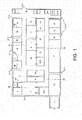
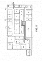
- FIG. 1 shows the plant according to the invention for processing contaminated residues in a schematic representation consisting of the building 27, in which the contact surface is, the locks 1.1, 1.2, through the contaminated parts such as a steam generator 32 or small contaminated parts individually or in a 20 ' -Container enter the building 27.
- the contact surface is, the locks 1.1, 1.2
- the contaminated parts such as a steam generator 32 or small contaminated parts individually or in a 20 ' -Container enter the building 27.
- an entrance and exit 27.2 for persons on the top right and emergency exits 27.3 are arranged.
- Decontaminated material may exit the building 27 through the decontaminated material exit 27.4 on the upper right.
- Contaminated material can leave the building 27 through the locks 1.1, 1.2 again.
- On the contact surface 29 different processing stations are arranged, which are designated.
- the processing station flexible walls 28 are arranged.
- these flexible walls may be a tent or other suitable device represent.
- processing stations on the plant surface 29 may be the cutting area for large components (large component treatment) 15, a concrete surface treatment 22, a band saw 16, a thermal decomposition 12, a concrete crusher 21, a manual decomposition 13 with thin sheet processing 14, a mechanical-thermal decomposition, a load optimization, a CC measurement 25.2, a wet chemical contamination 10 or a high-pressure water jet 8, a cable processing 17, a nonradioactive waste sorting tent 20, a radioactive waste sorting tent 19, an asbestos conditioning 18, a drying / cask measuring plant 3, a high pressure press 2, an ultrasonic bath 9, a Konrad container loading 4, act.
- large components large component treatment
- a concrete surface treatment 22 As processing stations on the plant surface 29 may be the cutting area for large components (large component treatment) 15, a concrete surface treatment 22, a band saw 16, a thermal decomposition 12, a concrete crusher 21, a manual decomposition 13 with thin sheet processing 14, a mechanical-thermal decomposition, a load optimization, a CC measurement 25.2, a wet
- the contact area on the right side has an area with low dose rate processing stations, in the middle an area with medium dose rate processing stations and on the left one area with high dose rate processing stations.
- This has the advantage that heavily contaminated parts are in one area and less heavily contaminated parts are in the other area.
- the high dose rate area is located opposite the entrance and exit 27.2 for persons and the exit 27.4 for decontaminated material. Parts with a high dose rate are in the high dose rate range and can also leave the contact area in this area without entering the other areas.
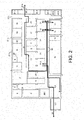
- FIG. 2 shows the way of contaminated and decontaminated metal or steel parts 30, 31 through the plant according to the invention.
- the delivery takes place through the inner and the outer lock 1.1, 1.2 in a 20 'container.
- the metal parts 30, 31 are removed therefrom by a suitable transport device and fed to the manual dismantling 13 of the thin sheet metal processing 14 or the thermal decomposition 12.
- the metal parts 30, 31 can be unscrewed and provided with eyebolts.
- the parts can be disassembled for example by sawing or cutting. This decomposition can be done automatically. Thereafter, the metal parts through the plant to Transported decontamination.
- the decontamination can be carried out in a known manner by means of high-pressure cleaning, a dry steel method, a shot blast method, a blast wheel method or a blasting box method.
- the decontamination by means of phosphoric acid at a contact time of 5 to 6 hours takes place in the plant and in FIG. 2 in a wet decontamination 10.
- the treated parts are stored on a buffer surface 24 and fed to a pre-measuring region 26 for a preliminary and final measurement, whereupon decontaminated metallic steel parts 31 leave the plant.
- Contaminated steel parts 30 are transported after the contamination measurement 25.2 on the locks 1.1, 1.2, if necessary by means of containers from the building 27 or again subjected to decontamination.
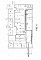
- the FIG. 3 shows the plant for the processing of residues and the way of waste through this plant.
- waste such as contaminated residues 33 through the locks 1.1, 1.2 in the system, in the present case by a 20 'container.
- This is transported to the sorting tent for radioactive waste 19 and sorted into conventional and radioactive waste.
- Uncontaminated waste is sent to conventional incineration.
- the radioactive waste is separated into flammable and non-flammable waste, the combustible radioactive waste being pressed and subsequently sent to incineration and the radioactive non-flammable waste from a high-pressure press 2 and a drying 3, after which the radioactive waste is sent to repository (Konrad) container 4 filled and fed through the locks 1.1, 1.2 a repository.
- repository Konrad
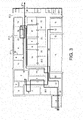
- FIG. 4 shows the plant for processing waste and the way a steam generator 32 through this system.
- the steam generator 32 and its parts are first disassembled in the large-component decomposition 15.
- band saws 16 are arranged, which break the steam generator 32 into easily transportable parts.
- a further decomposition takes place as a thermal decomposition 12, in which the steam generator 32 or individual parts is separated into smaller parts by means of separating welding.
- the individual parts of the steam generator 32 are then supplied to a measurement of the dose rate 25.2.
- Contaminated steel parts 30 leave the plant via the locks 1.1, 1.2.
- Decontaminated parts are fed to the wet decontamination plant 10, in which a decontamination takes place.
- the machined parts are stored on a buffer surface 24. Parts that correspond to the decision measurement in the pre-measurement area 26 are decontaminated, they can leave the plant via the exit for decontaminated material 27.4 for recycling.
- the FIG. 5 shows the plant for the processing of residues and the way of mineral residues 37 like concrete parts through this plant.
- the mineral residues such as concrete parts, such as concrete slabs, which represent components in a power plant building, are delivered by container through the outer and inner sluice 1.1, 1.2, unloaded and transported by gantry crane in the concrete surface processing 22.
- the contaminated surfaces may then be abraded in the concrete surface treatment 22, with the contaminated abraded surfaces being fed to the (Konrad) container shipping 4, while the decontaminated concrete bars or plates 38 again pass through the concrete surface processing 22 and the decontaminated material exit 27.4 Leave the plant.
- FIG. 6 shows the cross section of a nuclear power plant 50, which is to be dismantled.
- Various nuclide vectors can be assigned to the individual groups of metal parts within the containment 51.
- Another nuclide vector may be associated with the z-shaped concrete cover bars 52 that form the cover of the containment 51.
- Another nuclide vector may be associated with the pumping space 53, in which there are machines and vessels with which water is pumped through the secondary cooling system.
- a common cause of radioactive contamination is leakage in the secondary cooling system, such as repair or replacement of the pumps 54.
- Contaminated water runs on the floor 55 of the pump room 53 and runs under the pumps, into the corners and into cracks and voids of the concrete floor
- FIG. 6 shows a conceptual cross section of a nuclear power plant 50, which is being dismantled.
- the floors 55, walls and z-shaped concrete cover bars 52 of the nuclear power plant 50 are typically provided with a two component epoxy coating or urethane coating.
- the walls are usually coated up to a few meters high. After a leak, for example, the floor can be wiped off. In the concrete, however, cracks can form and depressions can occur due to falling parts. Contamination can not always be removed from gaps and cracks.
- FIG. 7 shows a cross section of the concrete floor 56 in which a crack has formed after the bottom was originally provided with a decontamination varnish 58.
- a decontamination varnish 58 After the formation of the crack 57 in the soil, radioactive liquid leaked out into the crack 57. Although the contaminated site was almost completely cleaned, the contamination at the deepest point of the crack 57 could not be removed.
- the concrete floor 56 has been provided with a new coating 60 to seal the contamination and to ensure future cleaning.
- several coatings were applied to the concrete floor 56 including the cover layer 61.
- the walls and z-shaped concrete cover bars 52 of the nuclear power plant 50 are similarly coated.
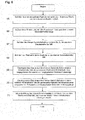
- FIG. 8 shows in a flow chart of steps 65-71 a method in which dust that exceeds the threshold is separated from the dust that is below the threshold.
- the limit to which the material is released for conventional waste disposal is 0.1 Bq / g (for Co-60).
- the concrete contaminated with radioactive particles is processed into dust by grinding or chipping.
- This dust is produced e.g. when the coating 60-61 is removed from the concrete surface of the concrete floor 56 or z-shaped concrete cover bar 52 when a nuclear power plant 50 is being dismantled.
- the dust contains both concrete and color particles.
- a negative pressure is built up, which sucks the dust first into a hose 87 and then into a dust separator 81.
- the negative pressure is generated for example by a vacuum pump 72, which is arranged spatially separated at the other end of the vacuum line. The dust is sucked off during the grinding of the coating.
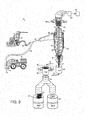
- FIG. 9 shows a system for the separation of radioactively contaminated material 73 and illustrates the machines used to carry out the in FIG. 8 described method can be used.
- a manual, 74 shown which removes the top layer of the concrete floor with the help of three diamond-ground, conically shaped cup wheels.
- a Husqvarna PG820 is used.
- a trenched concrete milling machine called The Moose, 76, manufactured by Fa. Pentek, is used.
- the concrete milling machine with chassis 76 removes the top layer of a concrete floor with the help of oscillating, Carbide tipped chisels 77.
- the floor can be sanded or chiselled into strips of 30cm width.
- the resulting dust is drawn into a vacuum hose 78, the suction opening 79 is positioned close to the point of grinding or chiselling.
- the dust passes through the vacuum hose 78 into the inlet dust separator 80 of the dust collector 81.
- the dust collector 81 is a cyclone separator or filter.
- FIG. 9 shows a sectional view of a Staubabscheiders 81 with a cylindrical attachment 82, which protrudes from the upper end of the separator. The sucked air flows through the inlet dust collector 80 into the dust collector 81 and exits through the cylindrical cap 82.
- the dust collector 81 has a cylindrical shell 84, a conical lower part 85 and no moving parts. Due to the centrifugal force created by the tangential velocity of the air in the downward movement along the inner walls of the dust collector 81, the dust particles 87 are separated from the air stream 83.
- a worm-shaped baffle is mounted around the outside of the cylindrical cap 82 in the upper end of the cylindrical shell 84 to direct the flow of the incoming air stream 83 into a downward spiral.
- the dust 87 is then passed through the bottom opening in the conical bottom, while the air stream 83 rises through the center of the dust collector 81 and leaves it through the cylindrical attachment 82.
- the dust collector 81 has a lower conical collecting container 86 with a narrower bottom opening, through which the dust 87 falls into one of the two small collecting containers 88/89.
- the dust collector 81 is well suited to filter the contaminated concrete dust from the air stream 83, since the dust collector 81 has no filter membrane that needs to be emptied or clogged. Since the dust collector 81 has no moving parts, it can be operated for a long period without maintenance. Although the dust collector 81 filters most of the dust 87 from the air stream 83, many dust particles smaller than 0.5mm in diameter travel upwardly with the air stream 83 and through the cylindrical cap 82.
- a filter such as a ceramic candle blower filter 90, is arranged above the cylindrical attachment 82 and is used to filter out dust particles with a diameter smaller than 0.5 mm.
- the airflow 83 flows in through the bottom of the ceramic inflatable candle filter 90 and out through the sides of the cylinder. Thus, the small particles of the dust 87 remain on the inside of the cylinder.
- a fine particle cake builds up on the filter element. As the cake thickens, lumps 91 break off and fall back through the dust collector 81 and into the small reservoirs 88/89 filled with the larger dust particles.
- the inflatable candle filter 90 is cleaned by an opposite surge of air pressure. This process removes the entire fine particle cake from the filter element.
- the cake consisting of dust lumps 91, falls to the bottom of the dust collector 81 and into the small collection containers 88/89.
- the filter cleaning is performed periodically to keep the ceramic inflatable candle filter 90 clean.
- step 67 of the flowchart ( FIG. 8 ) a small header 88 or 89 is filled with the dust 87 and 91 falling from the dust collector 81.
- both small collecting containers 88 and 89 are positioned below the dust collector 81 by means of a conveyor 75.
- Each small container 88 and 89 has a capacity of about 10 l, which corresponds to about 7 kg of concrete dust. This in turn has a density of about 700kg / m 3 . It takes just over 2 minutes to fill the two 10-liter containers 88 and 89 when using a concrete cutter with chassis 76 or a manual 74, which produces about 200 kg of concrete dust per hour.
- the other small reservoir 89 is placed under the dust separator 81 in position so that its filling can begin.
- the small collection container 89 is filled with dust and was placed in the activity meter 92.
- the small collecting container 88 is filled with dust 87 and 91.
- step 68 of the flowchart is measured by means of the activity meter 92, the radioactivity of the dust in the small collection container 89.
- the measuring device 92 uses the coincidence method to determine the activity of the radionuclide cobalt-60 in the dust 87 and 91.
- FIG. 10 illustrates the coincidence-based cobalt coincidence meter 92 in more detail.
- the activity meter 92 has two oppositely disposed sets of gamma detectors 90 degrees offset from each other.
- a gamma ray detector consists of a plastic scintillation detector 93 combined with a fast photomultiplier tube (PMT) 94 which amplifies the light emitted by the plastic scintillation detector 93.
- the plastic scintillation detector 93 is equipped with a crystal that emits light as soon as gamma rays arrive. The intensity of the light is proportional to the strength of the gamma radiation.
- the plastic scintillation detector 93 is coupled to the fast photomultiplier 94, which converts the light into electrons and then amplifies the electrical impulses generated by the electrons.
- a second gamma detector is located directly opposite the first gamma detector and is equipped with another plastic scintillation detector 95 and another fast one Photomultiplier 96 equipped.
- the second set of gamma detectors is oriented 90 degrees off the axis of the first set of gamma detectors to provide wider coverage of the 360 degree emission range.
- the activity meter 92 is a modified version of the large capacity monitor (LAM12) manufactured by Thermo Scientific of Er GmbH.
- the activity meter 92 measures activity by counting and determining the angular correlations of two consecutive gamma rays emitted from each cobalt 60 isotope present in the dust.
- the coincidence method registers gamma radiation ( ⁇ 1) from the decay of a cobalt-60 isotope in the plastic scintillation detector 93 and another gamma radiation ( ⁇ 2) from the same decay in the plastic scintillation detector 95.
- the activity meter 92 then counts only the coincidences , which were also registered simultaneously by the two opposite plastic scintillation detectors 93, 95. In this way, the background radiation can be detected and calculated out accordingly in the evaluation.
- the number of cobalt-60 isotopes per second is recorded and named in Becquerel (number in the second).
- the cobalt-coincidence method for measuring radioactivity is faster than other methods and may determine during filling of the small collection container 88 whether the dust in the first filled small collection container 89 can be released for general disposal because the dust is nuclear decay below the Release limit of 0.1 Bq / g or 100 Bq / kg.
- Each of the small reservoirs 88 and 89 has a capacity of approximately 7 kg of dust so that the release limit is exceeded when the activity meter 92 determines a probabilistic equivalent of more than 700 actual hits per second or 7,000 hits per 10 seconds.
- the activity measurement can be performed within the 10-second interval, in good time before the small sump 89 must be returned to the position below the dust collector 81 for the next quantum of dust 87 and 91 record.
- the dust 87 and 91 is transferred from the small collection container 89 into a waste container 97 when the activity detected within a predetermined period of time exceeds a predetermined limit.
- the time is set at 10 seconds
- the predetermined limit is 0.1 Bq / g or 7000 hits within that 10 seconds for 7 kg of dust in the small reservoir 89.
- the predetermined time is 1 second
- the default limit is 700 hits per second for 7 kg of dust in the small reservoir 89.
- the activity measurement is performed ten times and the predetermined limit is exceeded if the actual hits during the average ten predetermined time periods exceed 700 lie.
- the waste container 97 is a 200 liter capacity metal drum that can hold the volume of 20 small storage containers 88 and 89 with radioactive dust.
- FIG. 9 shows the case that the activity meter 92 has detected an activity value in the dust of the small collecting container 89 exceeding the predetermined limit value.
- the dust is directed by means of a two-way flap 98 into the waste container 97.
- the valve in the two-way valve 98 directs the dust from the small collection container 89 in the waste container 97.
- the two-way valve 98 by the company EMDE, Zierenberg, Germany, manufactured. By passing only the lesser amount of dust having higher activity into the waste container 97, only a lesser total amount of more activated dust is produced, which can be stored more safely and economically. This more activated dust will later be packed in Konrad containers and transported to final disposal.
- step 70 of the flowchart the dust 87 and 91 from the small collection container 89 is loaded into a waste container 99, if the measured activity value within the predetermined time does not exceed the predetermined limit.
- This waste container 99 is provided for released material that can be disposed of together with general construction waste.
- the two-way door 98 transports the dust sorted out of the small reservoir 89 into the waste container 99, provided that the activity meter 92 detects a probability of less than 7,000 actual hits in the 7 kg of dust from the small reservoir 89 during the 10 second duration measurement interval.
- step 71 of the flowchart the small sump 89 is again filled with dust 87 and 91 which falls from the dust collector 81 after the dust has been transferred to either the waste bin 97 or the waste bin 99 in steps 69-70 of the flowchart.
- Each of the small receptacles 88 and 89 is introduced into the activity meter 92 after it has been filled with dust.
- the dust can fall through the bottom of the small collection container in the two-way valve 98 through which the dust falls into either the waste container 97 or into the waste container 99.
- the bottom of the small collection container may be opened to allow the dust to fall through the opening in the bottom of the activity meter 92 and into the 98.
- the radioactively contaminated material removal system 73 includes a second detector 100 surrounding the ceramic, inflatable candle filter 90.
- the smaller dust particles that accumulate on the inner wall of the ceramic, inflatable candle filter 90 arrive from the suction port 79 in the ceramic, inflatable candle filter 90 before the larger dust particles fall out of the bottom opening of the dust collector 81 and well before the small reservoir 88-89 fills and the activity of the small collection container is measured.
- the activity measurement of the dust 91 on the ceramic inflatable candle filter 90 provides an early indication that radioactively contaminated dust arrives in the dust collector 81 and falls into the small reservoir 88-89. It is believed that at least 100 grams of dust accumulate on the ceramic candle blow-back filter 90, ie the predetermined limit of 0.1 Bq / g for detection of radioactively contaminated dust corresponds to an actual hit rate of at least 600 within the predetermined period of 60 seconds , In one embodiment, all cobalt 60 decays are counted within a continuous 60 second period of time. In another embodiment, the predetermined time period is a time window of 60 seconds. Every second, the second detector 100 determines if at least 600 actual hits have occurred during the last 60 seconds.
- the dust filled small receptacle 88 or 89 is immediately emptied into the radioactive waste receptacle 97 without completion to wait for the filling of the small collection container. Then, the filling of the small collection container begins again and will continue as long as the predetermined limit is not exceeded within a corresponding predetermined period of time.
- the activity measurement of the detector 100 is periodically interrupted during the blow-back phase while the ceramic blow-back candle filter 90 is being cleaned.
- the radioactively contaminated material removal system 73 also includes a police filter 101 disposed after the ceramic candle blow-back filter 90 to scavenge the particles that may be carrying the ceramic candle blow-back filter 90 have happened.
- the police or emergency filter 101 rarely needs to be changed and can be disposed of in the waste bin 97 without significantly increasing the amount of radioactive waste.
- the fixed period of time during which the activity meter 92 measures the activity of the dust 87 and 91 is reduced to 1 second to allow more constant flow and separation of the contaminated dust from released dust.
- the release limit remains at 0.1 Bq / g.
- the release threshold is increased if the activity meter 92 detects more than 700 actual hits from the 7 kg of dust in the small collection bin 88-89 within the predetermined time period of 1 second determined.
Landscapes
- Engineering & Computer Science (AREA)
- Physics & Mathematics (AREA)
- General Engineering & Computer Science (AREA)
- High Energy & Nuclear Physics (AREA)
- Architecture (AREA)
- Plasma & Fusion (AREA)
- Civil Engineering (AREA)
- Structural Engineering (AREA)
- Life Sciences & Earth Sciences (AREA)
- Food Science & Technology (AREA)
- Processing Of Solid Wastes (AREA)
- Measurement Of Radiation (AREA)
Priority Applications (1)
| Application Number | Priority Date | Filing Date | Title |
|---|---|---|---|
| SI201431416T SI2833367T1 (sl) | 2013-08-02 | 2014-08-01 | Obrat in postopek za obdelavo preostalih materialov |
Applications Claiming Priority (1)
| Application Number | Priority Date | Filing Date | Title |
|---|---|---|---|
| DE102013215250 | 2013-08-02 |
Publications (3)
| Publication Number | Publication Date |
|---|---|
| EP2833367A2 true EP2833367A2 (fr) | 2015-02-04 |
| EP2833367A3 EP2833367A3 (fr) | 2015-04-29 |
| EP2833367B1 EP2833367B1 (fr) | 2019-10-30 |
Family
ID=51260701
Family Applications (1)
| Application Number | Title | Priority Date | Filing Date |
|---|---|---|---|
| EP14179429.7A Revoked EP2833367B1 (fr) | 2013-08-02 | 2014-08-01 | Installation et procédé destinés au traitement de résidus |
Country Status (6)
| Country | Link |
|---|---|
| US (1) | US9302294B2 (fr) |
| EP (1) | EP2833367B1 (fr) |
| ES (1) | ES2758707T3 (fr) |
| HU (1) | HUE046950T2 (fr) |
| LT (1) | LT2833367T (fr) |
| SI (1) | SI2833367T1 (fr) |
Cited By (9)
| Publication number | Priority date | Publication date | Assignee | Title |
|---|---|---|---|---|
| US9302294B2 (en) | 2013-08-02 | 2016-04-05 | Babcock Noell Gmbh | Separating radioactive contaminated materials from cleared materials resulting from decommissioning a power plant |
| DE102017123426A1 (de) | 2017-10-09 | 2019-04-11 | Rwe Power Aktiengesellschaft | Verfahren zum Rückbau einer kerntechnischen Anlage |
| AT520938B1 (de) * | 2018-04-12 | 2019-09-15 | Braun Maschf Gmbh | Fass-Zerlegeanlage |
| CN110469161A (zh) * | 2019-08-14 | 2019-11-19 | 安徽巢湖路桥建设集团有限公司 | 用于桥梁施工的装配式预制厂及其施工方法 |
| DE102018216680B3 (de) * | 2018-09-28 | 2019-12-05 | Siemens Aktiengesellschaft | Verfahren zum Rückbau einer großtechnischen Anlage und mobiles Leittechniksystem für den Rückbau derselben |
| DE102019121004A1 (de) * | 2019-08-02 | 2021-02-04 | RWE Nuclear GmbH | Verfahren zum Errichten einer Vorrichtung zum Rückbau einer Industrieanlage |
| WO2021129989A1 (fr) * | 2019-12-23 | 2021-07-01 | Ald Vacuum Technologies Gmbh | Nettoyage de gaz de dégagement pour installations de frittage de mox à séparateur à cyclone intégré |
| FR3131065A1 (fr) * | 2021-12-21 | 2023-06-23 | Electricite De France | Procédé de gestion d’un déchet nucléaire |
| FR3130955A1 (fr) * | 2021-12-21 | 2023-06-23 | Electricite De France | Procédé de caractérisation d’un déchet nucléaire |
Families Citing this family (15)
| Publication number | Priority date | Publication date | Assignee | Title |
|---|---|---|---|---|
| CN105823707B (zh) * | 2016-05-09 | 2018-11-13 | 北京华夏力鸿商品检验有限公司 | 一种煤炭堆密度测定装置及方法 |
| US11794141B2 (en) * | 2021-01-25 | 2023-10-24 | Omachron Intellectual Property Inc. | Multiuse home station |
| CN108288511A (zh) * | 2017-06-19 | 2018-07-17 | 中国工程物理研究院材料研究所 | 放射性废过滤器的前处理方法及前处理装置 |
| JP6914165B2 (ja) * | 2017-10-27 | 2021-08-04 | 株式会社日立製作所 | シンチレータユニット、放射線測定装置及び放射線測定方法 |
| KR102061287B1 (ko) * | 2018-04-17 | 2019-12-31 | 한국수력원자력 주식회사 | 가압 경수로형 원자력 발전소의 생체 보호 콘크리트의 해체 및 제염 시스템및 방법 |
| JP7092621B2 (ja) * | 2018-08-31 | 2022-06-28 | 三菱重工業株式会社 | 原子力機器処理施設、原子力機器の処理方法 |
| DE102021000011A1 (de) | 2021-01-06 | 2022-07-07 | Lean Corporation GmbH | Mobiles und digitales Bearbeitungszentrum für die Bearbeitung, Bemessung, Prüfung und Freigabe von aktivierten, kontaminierten und/oder nicht kontaminierten, nuklearen Reststoffen, bestehend aus dafür speziell entwickelten und per LKW transportierbaren Containern |
| KR102286978B1 (ko) * | 2021-02-03 | 2021-08-06 | 주식회사 이건 | 건식 절단 공법으로 절단하여 발생한 이물질을 집진하기 위한 와이어쏘 장치 |
| FI131121B1 (en) * | 2021-06-28 | 2024-10-14 | Teknologian Tutkimuskeskus Vtt Oy | A method for sampling a solid body, and a system configured to sample a solid body |
| JP7731271B2 (ja) * | 2021-11-26 | 2025-08-29 | 富士電機株式会社 | 廃ケーブル処理システム |
| KR102737203B1 (ko) * | 2022-11-16 | 2024-12-03 | (주)나일프렌트 | 슬러지 수집장치 |
| KR102838066B1 (ko) * | 2023-04-27 | 2025-07-24 | 주식회사 오르비텍 | 중수로 원전 해체물량 평가 방법 |
| DE102023115174B3 (de) | 2023-06-09 | 2023-11-09 | Dornier Nuclear Services GmbH | Verfahren zur Bearbeitung aktivierter und/oder kontaminierter metallischer Reststoffe und Verwendung von Big Bags |
| DE102023115175B3 (de) | 2023-06-09 | 2023-11-09 | Dornier Nuclear Services GmbH | Verfahren zur Bearbeitung aktivierter und/oder kontaminierter metallischer Reststoffe und Verwendung von Big Bags |
| CN117671497B (zh) * | 2023-12-04 | 2024-05-28 | 广东筠诚建筑科技有限公司 | 一种基于数字图像的工程建筑废料分类方法及装置 |
Citations (7)
| Publication number | Priority date | Publication date | Assignee | Title |
|---|---|---|---|---|
| DE2638174A1 (de) | 1976-08-25 | 1978-03-02 | Steinmueller Gmbh L & C | Verfahren zur entsorgung eines kernkraftwerkes |
| US5037159A (en) | 1988-12-30 | 1991-08-06 | Nutter Victor H | Apparatus for collecting and packaging hazardous particulate materials |
| EP0638516A1 (fr) | 1993-08-14 | 1995-02-15 | Hoechst Aktiengesellschaft | Procédé pour l'élimination du plomb et du cadmium contenus dans l'acide phosphorique |
| DE19549302A1 (de) | 1995-12-22 | 1997-06-26 | Gustav Pegel & Sohn Gmbh & Co | Verfahren zur Konditionierung von Asbest |
| EP1794297A1 (fr) | 2004-09-21 | 2007-06-13 | Novozymes A/S | Subtilases |
| WO2012175098A1 (fr) | 2011-06-23 | 2012-12-27 | Babcock Noell Gmbh | Procédé et installation de décontamination d'une solution d'acide phosphorique |
| WO2013175089A1 (fr) | 2012-05-24 | 2013-11-28 | Air Liquide Sante (International) | Conditionnement à haute pression d'un mélange gazeux no/azote |
Family Cites Families (37)
| Publication number | Priority date | Publication date | Assignee | Title |
|---|---|---|---|---|
| DE1546682A1 (de) | 1965-02-17 | 1970-10-08 | Siemens Ag | Verfahren zur Filterung von mit radioaktiven Stoffen verunreinigten Gasen |
| JPS5932960Y2 (ja) | 1980-05-02 | 1984-09-14 | 動力炉・核燃料開発事業団 | 放射性汚染物体解体用グリ−ンハウス |
| FR2515408A1 (fr) | 1981-10-22 | 1983-04-29 | Delta Protection | Dispositif de sas destine a la communication avec une enceinte contaminee |
| US4646978A (en) | 1984-09-10 | 1987-03-03 | Westinghouse Electric Corp. | Method for sorting radioactive waste |
| JPS6269181A (ja) | 1985-09-24 | 1987-03-30 | Toshiba Corp | 物品搬出モニタ |
| FR2630856B1 (fr) | 1988-04-28 | 1990-08-31 | Poujaud Robert | Dispositif de mur modulable de protection biologique anti-radiations |
| WO1989012305A1 (fr) | 1988-06-07 | 1989-12-14 | Nutech, Inc. | Procede de decontamination en particulier de materiaux plastiques selectionnes et classiques qui ont ete contamines par radioactivite, et articles |
| US4855080A (en) | 1988-06-07 | 1989-08-08 | Nutech, Inc. | Method for decontaminating specially selected plastic materials which have become radioactively contaminated, and articles |
| JPH0278989A (ja) | 1988-09-14 | 1990-03-19 | Nippon Atom Ind Group Co Ltd | 放射性廃棄物の放射能レベル選別装置 |
| DE68926493T2 (de) | 1988-12-21 | 1996-09-19 | Hitachi Ltd | System zum Unterscheiden von durch Strahlung verseuchten Bruchstücken und Gerät, um die Radioaktivität der Bruchstücke zu messen |
| DE3903320A1 (de) | 1989-02-04 | 1990-08-16 | Kernforschungsz Karlsruhe | Verfahren zur entsorgung und wiederverwertung von teilweise schwachkontaminierten kabeln aus kerntechnischen anlagen |
| JPH034191A (ja) * | 1989-06-01 | 1991-01-10 | Hitachi Plant Eng & Constr Co Ltd | 放射能汚染密度の測定方法 |
| JP3127313B2 (ja) | 1991-09-13 | 2001-01-22 | 大成建設株式会社 | 放射能拡散防止ハウス |
| US5301388A (en) | 1992-12-04 | 1994-04-12 | Zeren Joseph D | Critically safe vacuum pickup for use in wet or dry cleanup of radioactive materials |
| DE4319095C2 (de) | 1993-06-08 | 1995-04-20 | Siemens Ag | Vorrichtung zur Dekontamination einer radioaktiv kontaminierten Oberfläche |
| US5601479A (en) * | 1994-09-28 | 1997-02-11 | Santos; Eugene W. | Method and apparatus for decontaminating structures |
| JP2928738B2 (ja) | 1995-02-02 | 1999-08-03 | 核燃料サイクル開発機構 | グローブボックスとグリーンハウスの気密接続・分離方法 |
| DE19625464C2 (de) | 1996-06-26 | 2002-02-21 | Kernkraftwerke Gundremmingen | Verfahren zur Entsorgung und Vorbereitung der Wiederverwendung von radioaktiv kontaminiertem Kabelmaterial und Anlage zur Durchführung des Verfahrens |
| DE29622583U1 (de) * | 1996-12-31 | 1997-03-20 | Buchen Gmbh Richard | Mobile Dekontaminationsanlage in Modulbauweise zur Dekontamination von radioaktiven und sonstigen gesundheitsgefährdenden Materialien und Stoffen |
| US6438191B1 (en) | 1998-03-31 | 2002-08-20 | Sandia Corporation | Explosive scabbling of structural materials |
| DE19824039B4 (de) | 1998-05-29 | 2004-07-15 | Nukem Hanau Gmbh | Verfahren und Vorrichtung zur Prüfung von Schüttmaterial, insbesondere von Bauschutt und/oder Bodenaushub, auf den Gehalt an Radionukliden |
| DE19854430A1 (de) | 1998-11-25 | 2000-06-08 | Esm Eberline Instr Strahlen Un | Verfahren und Einrichtung zum Messen der radioaktiven Kontamination eines Meßobjektes |
| WO2000077793A1 (fr) | 1999-06-14 | 2000-12-21 | Paul Scherrer Institut | Elimination de materiaux radioactifs |
| AU2003251880A1 (en) * | 2002-07-08 | 2004-01-23 | Global Solutions Systems, Llc | Method of converting waste to soil/feed modifiers |
| JP2004069400A (ja) | 2002-08-05 | 2004-03-04 | Achilles Corp | 除染テント |
| GB0222341D0 (en) | 2002-09-26 | 2002-11-06 | British Nuclear Fuels Plc | Surface treatment of concrete |
| RU31049U1 (ru) | 2003-01-08 | 2003-07-10 | Федеральное государственное унитарное предприятие научно-исследовательское, проектно-технологическое бюро "Онега" | Модульный комплекс по переработке радиоактивных отходов |
| US6833016B2 (en) * | 2003-03-27 | 2004-12-21 | Oneida Air Systems, Inc | Dust collection system |
| US7511292B2 (en) | 2004-10-28 | 2009-03-31 | Nfs-Radiation Protection Systems, Inc. | Radiation protection shield |
| KR100665508B1 (ko) | 2005-07-01 | 2007-01-09 | 한국원자력안전기술원 | 액체 혼합베타핵종 자동 방사능분석장치 |
| JP4960064B2 (ja) | 2005-11-04 | 2012-06-27 | 株式会社東芝 | 放射性金属廃棄物の処理方法および処理設備 |
| FR2902127B1 (fr) | 2006-06-12 | 2011-07-22 | Vladimir Grcevic | Unite mobile de decontamination de masse |
| JP5640318B2 (ja) | 2009-03-03 | 2014-12-17 | 東京電力株式会社 | 原子力発電所 |
| CN102852375B (zh) | 2011-04-19 | 2016-05-11 | 比利格核股份有限公司 | 保护性且一次性的封套状干预帐篷 |
| JP2013096959A (ja) | 2011-11-04 | 2013-05-20 | Shiyouichi Yoshino | 放射能除染方法 |
| JP5850494B2 (ja) * | 2011-11-18 | 2016-02-03 | 太平洋セメント株式会社 | 放射性セシウムの除去方法及び除去装置 |
| US9302294B2 (en) | 2013-08-02 | 2016-04-05 | Babcock Noell Gmbh | Separating radioactive contaminated materials from cleared materials resulting from decommissioning a power plant |
-
2014
- 2014-07-15 US US14/332,343 patent/US9302294B2/en not_active Expired - Fee Related
- 2014-08-01 ES ES14179429T patent/ES2758707T3/es active Active
- 2014-08-01 EP EP14179429.7A patent/EP2833367B1/fr not_active Revoked
- 2014-08-01 HU HUE14179429A patent/HUE046950T2/hu unknown
- 2014-08-01 LT LT14179429T patent/LT2833367T/lt unknown
- 2014-08-01 SI SI201431416T patent/SI2833367T1/sl unknown
Patent Citations (7)
| Publication number | Priority date | Publication date | Assignee | Title |
|---|---|---|---|---|
| DE2638174A1 (de) | 1976-08-25 | 1978-03-02 | Steinmueller Gmbh L & C | Verfahren zur entsorgung eines kernkraftwerkes |
| US5037159A (en) | 1988-12-30 | 1991-08-06 | Nutter Victor H | Apparatus for collecting and packaging hazardous particulate materials |
| EP0638516A1 (fr) | 1993-08-14 | 1995-02-15 | Hoechst Aktiengesellschaft | Procédé pour l'élimination du plomb et du cadmium contenus dans l'acide phosphorique |
| DE19549302A1 (de) | 1995-12-22 | 1997-06-26 | Gustav Pegel & Sohn Gmbh & Co | Verfahren zur Konditionierung von Asbest |
| EP1794297A1 (fr) | 2004-09-21 | 2007-06-13 | Novozymes A/S | Subtilases |
| WO2012175098A1 (fr) | 2011-06-23 | 2012-12-27 | Babcock Noell Gmbh | Procédé et installation de décontamination d'une solution d'acide phosphorique |
| WO2013175089A1 (fr) | 2012-05-24 | 2013-11-28 | Air Liquide Sante (International) | Conditionnement à haute pression d'un mélange gazeux no/azote |
Non-Patent Citations (15)
| Title |
|---|
| "Genehmigung nach § 3StrlSchV (a.F.) zur Konditionierung und Zwischenlagerung von radioaktiven Reststoffen/Abfällen im Zwischenlager Nord (ZLN) in Rubenow", INNENMINISTERIUM MECKLENBURG-VORPOMMERN, 20 February 1998 (1998-02-20), XP055402342 |
| "Genehmigung ZLN Zwischenlager Nord", BUNDESAMT FÜR STRAHLENSCHUTZ, 5 November 1999 (1999-11-05), pages 1 - 115, XP055402253, Retrieved from the Internet <URL:URL:http://www.bfe.bund.de/DE/ne/zwischenlager/zentral/nord/nord_node.html> |
| "Schleuderrad", WIKIPEDIA, 9 September 2012 (2012-09-09), pages 1, XP055403558, Retrieved from the Internet <URL:https://de.wikipedia.org/wiki/Schleuderrad> |
| "SynergiePark Lubmin - Visionen werden Wirklichkeit", 2010, article "4. Pionierleistung ohne Beispiel", pages: 58 - 77, XP055582454 |
| CARSTEN F. ET AL: "15 years practical decommissioning experiences at Greifswald NPP", CEE DECOMMISSIONING & WASTE COOPERATION, - 19 June 2008 (2008-06-19), Berlin, XP055404456 |
| HELFRIED LIEBSCH ET AL: "SynergiePark Lubmin - Visionen werden Wirklichkeit", 2010, EDITION KLAGEO, pages: 58 - 77, XP055404453 |
| ICC-HOFMANN: "Ausschreibungen Dekontaminationseinrichtungen - D-Philippsburg", DOKURNENT NR: 195896-2006, - 27 September 2006 (2006-09-27), pages 1 - 2, XP055404460, Retrieved from the Internet <URL:http://www.icc-hofmann.de> |
| INNENMINISTERIUM MECKLENBURG-VORPOMMERN: "Genehmigung nach § 3StrlSchV (a.F.) zur Konditionierung und Zwischenlagerung von radioaktiven Reststoffen/Abfällen im Zwischenlager Nord (ZLN), Rubenow vom 20.02.1998", 11 December 2007, XP055402342 |
| JACOBS P. ET AL: "Die zweite Chance - Abbau und Aufbruch am KKW-Standort Lubmin", 15 October 2004, W&M, pages: 47,58-61,64 - 65,72-73, XP055403566 |
| MASCIALE M.: "Manual on Maintenance Coatings for Nuclear Power Plants", vol. 8, December 1990, ASTM, article "Coating Materials", pages: 18 - 22, XP055404455 |
| RITTSCHER D ET AL: "Kernkraftwerke Greifswald und Rheinsberg: Stilllegung, Abbau und Aufbau", INTERNATIONALE ZEITSCHRIFT FÜR KERNENERGIE, vol. 47, no. 4, April 2002 (2002-04-01), pages 235 - 243, XP055402261 |
| RITTSCHER D. ET AL.: "Kernkraftwerke Greifswald und Rheinsberg: Stilllegung, Abbau und Aufbau", INTERNATIONALE ZEITSCHRIFT FÜR KERNENERGIE, vol. 47, no. 4, April 2002 (2002-04-01), pages 235 - 243, XP055402261 |
| RITTSCHER D; KRAUSE F: "Kernkraftwerke Greifswald und Rheinsberg: Stillegung, Abbau und Aufbau", NTERNATIONALE ZEITSCHRIFT FÜR KERNENERGIE, vol. 47, no. 4, - April 2002 (2002-04-01), pages 235 - 243, XP055402261 |
| S. THIERFELD: "Stilllegung und Rückbau kerntechnischer Anlagen", 30 September 2012, pages: 74 - 145, XP055419577 |
| THIERFELDT S. ET AL.: "Stilllegung und Rückbau kerntechnischer Anlagen. 4 Auflage", September 2012, pages: 74-77,80-81,86 - 89,96,109,128-145, XP055404452 |
Cited By (13)
| Publication number | Priority date | Publication date | Assignee | Title |
|---|---|---|---|---|
| US9302294B2 (en) | 2013-08-02 | 2016-04-05 | Babcock Noell Gmbh | Separating radioactive contaminated materials from cleared materials resulting from decommissioning a power plant |
| DE102017123426A1 (de) | 2017-10-09 | 2019-04-11 | Rwe Power Aktiengesellschaft | Verfahren zum Rückbau einer kerntechnischen Anlage |
| AT520938B1 (de) * | 2018-04-12 | 2019-09-15 | Braun Maschf Gmbh | Fass-Zerlegeanlage |
| AT520938A4 (de) * | 2018-04-12 | 2019-09-15 | Braun Maschf Gmbh | Fass-Zerlegeanlage |
| DE102018216680B3 (de) * | 2018-09-28 | 2019-12-05 | Siemens Aktiengesellschaft | Verfahren zum Rückbau einer großtechnischen Anlage und mobiles Leittechniksystem für den Rückbau derselben |
| DE102019121004A1 (de) * | 2019-08-02 | 2021-02-04 | RWE Nuclear GmbH | Verfahren zum Errichten einer Vorrichtung zum Rückbau einer Industrieanlage |
| WO2021023491A1 (fr) | 2019-08-02 | 2021-02-11 | RWE Nuclear GmbH | Procédé de montage d'un appareil de démantèlement d'une installation industrielle |
| EP4008012B1 (fr) | 2019-08-02 | 2022-11-30 | RWE Nuclear GmbH | Procédé de montage d'un appareil de démantèlement d'une installation industrielle |
| CN110469161A (zh) * | 2019-08-14 | 2019-11-19 | 安徽巢湖路桥建设集团有限公司 | 用于桥梁施工的装配式预制厂及其施工方法 |
| WO2021129989A1 (fr) * | 2019-12-23 | 2021-07-01 | Ald Vacuum Technologies Gmbh | Nettoyage de gaz de dégagement pour installations de frittage de mox à séparateur à cyclone intégré |
| EP3842152B1 (fr) * | 2019-12-23 | 2023-03-08 | ALD Vacuum Technologies GmbH | Épuration des gaz résiduels pour les installations de frittage de mox à cyclone intégré |
| FR3131065A1 (fr) * | 2021-12-21 | 2023-06-23 | Electricite De France | Procédé de gestion d’un déchet nucléaire |
| FR3130955A1 (fr) * | 2021-12-21 | 2023-06-23 | Electricite De France | Procédé de caractérisation d’un déchet nucléaire |
Also Published As
| Publication number | Publication date |
|---|---|
| SI2833367T1 (sl) | 2020-01-31 |
| EP2833367A3 (fr) | 2015-04-29 |
| EP2833367B1 (fr) | 2019-10-30 |
| LT2833367T (lt) | 2019-12-10 |
| ES2758707T3 (es) | 2020-05-06 |
| HUE046950T2 (hu) | 2020-04-28 |
| US20150034531A1 (en) | 2015-02-05 |
| US9302294B2 (en) | 2016-04-05 |
Similar Documents
| Publication | Publication Date | Title |
|---|---|---|
| EP2833367B1 (fr) | Installation et procédé destinés au traitement de résidus | |
| DE4332743A1 (de) | Verfahren und Anlage für die Aufarbeitung von metallbeschichteten Katalysatoren | |
| US8502179B1 (en) | Amalgam of crushed hazardous radioactive waste, such as spent nuclear fuel rods, mixed with copious amounts of lead pellets, also granulated, to form a mixture in which lead granules overwhelm | |
| DE4107982A1 (de) | Verfahren und vorrichtung zum beseitigen von tritium aus verseuchten objekten | |
| DE102023115175B3 (de) | Verfahren zur Bearbeitung aktivierter und/oder kontaminierter metallischer Reststoffe und Verwendung von Big Bags | |
| DE102023115174B3 (de) | Verfahren zur Bearbeitung aktivierter und/oder kontaminierter metallischer Reststoffe und Verwendung von Big Bags | |
| AT507022A1 (de) | Profilverlagerung neutroneninduzierter 60co-verteilung und schichtweise reduktion an einem primärkreis zum beschleunigten abbruch eines ausgedienten kernkraftwerks | |
| EP4008012B1 (fr) | Procédé de montage d'un appareil de démantèlement d'une installation industrielle | |
| Ponomarev-Stepnoi et al. | Extraction of radioactive wastes and liquidation of old repositories at the Russian Science Center Kurchatov Institute | |
| EP0106207B1 (fr) | Procédé de manipulation de déchets radioactifs | |
| DE3002697A1 (de) | Verfahren zum lagern radioaktiven abfalls | |
| DE3901783A1 (de) | Verfahren zum endlagern von schwachkontaminiertem bauschutt aus dem abriss kerntechnischer anlagen | |
| DE3414409A1 (de) | Einrichtung zur abtastung von radioaktiven ansammlungen in einer muellverbrennungsanlage | |
| KR20100079879A (ko) | 패들형 회전충격기를 구비한 방사성 콘크리트 폐기물의 감용 및 핵종제거 설비 | |
| Braehler et al. | Abrasive Blasting Unit (ABU) | |
| DE4437276A1 (de) | Verfahren und Vorrichtung zur Entsorgung einer aktivierten und/oder radioaktiv kontaminierten metallischen Komponente eines Kernkraftwerkes | |
| DE2847747A1 (de) | Einrichtung zum sammeln von radioaktiven, staub- oder pulverfoermigen stoffen | |
| DE102021000011A1 (de) | Mobiles und digitales Bearbeitungszentrum für die Bearbeitung, Bemessung, Prüfung und Freigabe von aktivierten, kontaminierten und/oder nicht kontaminierten, nuklearen Reststoffen, bestehend aus dafür speziell entwickelten und per LKW transportierbaren Containern | |
| Kunze et al. | Occupational exposure in radioactive waste management in Germany | |
| DE102016117703A1 (de) | Vorrichtung zur Behandlung von radioaktiv kontaminierten Abwässern | |
| Bodin et al. | COGEMA Experience on Retrieving and Automatically Remote Cutting Large Metallic Structures Using Special Saw During Nuclear Decommissioning Operations | |
| Volkov et al. | Main results of the second stage of liquidation of temporary radwaste repositories and rehabilitation of the radwaste disposal site at the Russian Research Center Kurchatov Institute | |
| Quade et al. | Release of Residues from Melting NORM-Contaminated Steel Scrap-A German Approach | |
| Nascimento Viana et al. | Use of segregation techniques to reduce stored low level waste | |
| fei; WANG Jian-xin; SHAO Yan-jiang; DU Hong-ming | Annual Treatment Operation Report of Radioactive Liquid Waste in Temporary Storage in 2015 |
Legal Events
| Date | Code | Title | Description |
|---|---|---|---|
| 17P | Request for examination filed |
Effective date: 20140801 |
|
| AK | Designated contracting states |
Kind code of ref document: A2 Designated state(s): AL AT BE BG CH CY CZ DE DK EE ES FI FR GB GR HR HU IE IS IT LI LT LU LV MC MK MT NL NO PL PT RO RS SE SI SK SM TR |
|
| AX | Request for extension of the european patent |
Extension state: BA ME |
|
| PUAI | Public reference made under article 153(3) epc to a published international application that has entered the european phase |
Free format text: ORIGINAL CODE: 0009012 |
|
| PUAL | Search report despatched |
Free format text: ORIGINAL CODE: 0009013 |
|
| AK | Designated contracting states |
Kind code of ref document: A3 Designated state(s): AL AT BE BG CH CY CZ DE DK EE ES FI FR GB GR HR HU IE IS IT LI LT LU LV MC MK MT NL NO PL PT RO RS SE SI SK SM TR |
|
| AX | Request for extension of the european patent |
Extension state: BA ME |
|
| RIC1 | Information provided on ipc code assigned before grant |
Ipc: G21F 7/00 20060101ALI20150325BHEP Ipc: G21D 1/00 20060101AFI20150325BHEP Ipc: G21F 9/00 20060101ALI20150325BHEP Ipc: E04B 1/00 20060101ALI20150325BHEP Ipc: G21F 3/00 20060101ALN20150325BHEP Ipc: G21F 9/30 20060101ALI20150325BHEP |
|
| R17P | Request for examination filed (corrected) |
Effective date: 20151028 |
|
| RBV | Designated contracting states (corrected) |
Designated state(s): AL AT BE BG CH CY CZ DE DK EE ES FI FR GB GR HR HU IE IS IT LI LT LU LV MC MK MT NL NO PL PT RO RS SE SI SK SM TR |
|
| 17Q | First examination report despatched |
Effective date: 20160812 |
|
| STAA | Information on the status of an ep patent application or granted ep patent |
Free format text: STATUS: EXAMINATION IS IN PROGRESS |
|
| GRAP | Despatch of communication of intention to grant a patent |
Free format text: ORIGINAL CODE: EPIDOSNIGR1 |
|
| STAA | Information on the status of an ep patent application or granted ep patent |
Free format text: STATUS: GRANT OF PATENT IS INTENDED |
|
| RIC1 | Information provided on ipc code assigned before grant |
Ipc: B07B 13/14 20060101ALI20170404BHEP Ipc: E04H 5/02 20060101ALI20170404BHEP Ipc: G21F 9/30 20060101ALI20170404BHEP Ipc: G21D 1/00 20060101AFI20170404BHEP Ipc: G21F 7/00 20060101ALI20170404BHEP Ipc: G21F 9/00 20060101ALI20170404BHEP Ipc: E04B 1/00 20060101ALI20170404BHEP Ipc: B07B 11/02 20060101ALI20170404BHEP Ipc: G21F 3/00 20060101ALN20170404BHEP |
|
| INTG | Intention to grant announced |
Effective date: 20170508 |
|
| GRAJ | Information related to disapproval of communication of intention to grant by the applicant or resumption of examination proceedings by the epo deleted |
Free format text: ORIGINAL CODE: EPIDOSDIGR1 |
|
| STAA | Information on the status of an ep patent application or granted ep patent |
Free format text: STATUS: EXAMINATION IS IN PROGRESS |
|
| TPAC | Observations filed by third parties |
Free format text: ORIGINAL CODE: EPIDOSNTIPA |
|
| RIN1 | Information on inventor provided before grant (corrected) |
Inventor name: PINGEL, SOENKE Inventor name: BOLLES, FRANK Inventor name: EDLER, GERD Inventor name: STARKE, HOLGER Inventor name: HEPPER, DR. RONALD |
|
| INTC | Intention to grant announced (deleted) | ||
| GRAP | Despatch of communication of intention to grant a patent |
Free format text: ORIGINAL CODE: EPIDOSNIGR1 |
|
| STAA | Information on the status of an ep patent application or granted ep patent |
Free format text: STATUS: GRANT OF PATENT IS INTENDED |
|
| RIC1 | Information provided on ipc code assigned before grant |
Ipc: G21F 3/00 20060101ALN20170831BHEP Ipc: B07B 13/14 20060101ALI20170831BHEP Ipc: G21F 9/30 20060101ALI20170831BHEP Ipc: G21F 7/00 20060101ALI20170831BHEP Ipc: G21D 1/00 20060101AFI20170831BHEP Ipc: B07B 11/02 20060101ALI20170831BHEP Ipc: E04B 1/00 20060101ALI20170831BHEP Ipc: E04H 5/02 20060101ALI20170831BHEP Ipc: G21F 9/00 20060101ALI20170831BHEP |
|
| TPAA | Information related to observations by third parties modified |
Free format text: ORIGINAL CODE: EPIDOSCTIPA |
|
| RIC1 | Information provided on ipc code assigned before grant |
Ipc: E04H 5/02 20060101ALI20170914BHEP Ipc: G21F 9/30 20060101ALI20170914BHEP Ipc: E04B 1/00 20060101ALI20170914BHEP Ipc: G21F 3/00 20060101ALN20170914BHEP Ipc: B07B 11/02 20060101ALI20170914BHEP Ipc: G21F 7/00 20060101ALI20170914BHEP Ipc: B07B 13/14 20060101ALI20170914BHEP Ipc: G21D 1/00 20060101AFI20170914BHEP Ipc: G21F 9/00 20060101ALI20170914BHEP |
|
| GRAJ | Information related to disapproval of communication of intention to grant by the applicant or resumption of examination proceedings by the epo deleted |
Free format text: ORIGINAL CODE: EPIDOSDIGR1 |
|
| STAA | Information on the status of an ep patent application or granted ep patent |
Free format text: STATUS: EXAMINATION IS IN PROGRESS |
|
| INTG | Intention to grant announced |
Effective date: 20171004 |
|
| GRAJ | Information related to disapproval of communication of intention to grant by the applicant or resumption of examination proceedings by the epo deleted |
Free format text: ORIGINAL CODE: EPIDOSDIGR1 |
|
| INTG | Intention to grant announced |
Effective date: 20170508 |
|
| INTC | Intention to grant announced (deleted) | ||
| RAP1 | Party data changed (applicant data changed or rights of an application transferred) |
Owner name: BABCOCK NOELL GMBH Owner name: ENBW ENERGIE BADEN-WUERTTEMBERG AG |
|
| TPAA | Information related to observations by third parties modified |
Free format text: ORIGINAL CODE: EPIDOSCTIPA |
|
| TPAC | Observations filed by third parties |
Free format text: ORIGINAL CODE: EPIDOSNTIPA |
|
| TPAC | Observations filed by third parties |
Free format text: ORIGINAL CODE: EPIDOSNTIPA |
|
| GRAP | Despatch of communication of intention to grant a patent |
Free format text: ORIGINAL CODE: EPIDOSNIGR1 |
|
| STAA | Information on the status of an ep patent application or granted ep patent |
Free format text: STATUS: GRANT OF PATENT IS INTENDED |
|
| RIC1 | Information provided on ipc code assigned before grant |
Ipc: G21F 9/30 20060101ALI20190402BHEP Ipc: G21D 1/00 20060101AFI20190402BHEP Ipc: B07B 13/14 20060101ALI20190402BHEP Ipc: G21F 7/00 20060101ALI20190402BHEP Ipc: E04H 5/02 20060101ALI20190402BHEP Ipc: B07B 11/02 20060101ALI20190402BHEP Ipc: E04B 1/00 20060101ALI20190402BHEP Ipc: G21F 3/00 20060101ALN20190402BHEP Ipc: G21F 9/00 20060101ALI20190402BHEP |
|
| INTG | Intention to grant announced |
Effective date: 20190502 |
|
| GRAS | Grant fee paid |
Free format text: ORIGINAL CODE: EPIDOSNIGR3 |
|
| TPAC | Observations filed by third parties |
Free format text: ORIGINAL CODE: EPIDOSNTIPA |
|
| GRAA | (expected) grant |
Free format text: ORIGINAL CODE: 0009210 |
|
| STAA | Information on the status of an ep patent application or granted ep patent |
Free format text: STATUS: THE PATENT HAS BEEN GRANTED |
|
| RAP1 | Party data changed (applicant data changed or rights of an application transferred) |
Owner name: BILFINGER NOELL GMBH Owner name: ENBW ENERGIE BADEN-WUERTTEMBERG AG |
|
| AK | Designated contracting states |
Kind code of ref document: B1 Designated state(s): AL AT BE BG CH CY CZ DE DK EE ES FI FR GB GR HR HU IE IS IT LI LT LU LV MC MK MT NL NO PL PT RO RS SE SI SK SM TR |
|
| REG | Reference to a national code |
Ref country code: GB Ref legal event code: FG4D Free format text: NOT ENGLISH |
|
| REG | Reference to a national code |
Ref country code: CH Ref legal event code: EP |
|
| REG | Reference to a national code |
Ref country code: CH Ref legal event code: NV Representative=s name: SCHMAUDER AND PARTNER AG PATENT- UND MARKENANW, CH Ref country code: AT Ref legal event code: REF Ref document number: 1197025 Country of ref document: AT Kind code of ref document: T Effective date: 20191115 |
|
| REG | Reference to a national code |
Ref country code: DE Ref legal event code: R096 Ref document number: 502014012941 Country of ref document: DE |
|
| REG | Reference to a national code |
Ref country code: NL Ref legal event code: FP Ref country code: IE Ref legal event code: FG4D Free format text: LANGUAGE OF EP DOCUMENT: GERMAN |
|
| REG | Reference to a national code |
Ref country code: SE Ref legal event code: TRGR |
|
| REG | Reference to a national code |
Ref country code: SK Ref legal event code: T3 Ref document number: E 32826 Country of ref document: SK |
|
| REG | Reference to a national code |
Ref country code: HU Ref legal event code: AG4A Ref document number: E046950 Country of ref document: HU |
|
| PG25 | Lapsed in a contracting state [announced via postgrant information from national office to epo] |
Ref country code: LV Free format text: LAPSE BECAUSE OF FAILURE TO SUBMIT A TRANSLATION OF THE DESCRIPTION OR TO PAY THE FEE WITHIN THE PRESCRIBED TIME-LIMIT Effective date: 20191030 Ref country code: NO Free format text: LAPSE BECAUSE OF FAILURE TO SUBMIT A TRANSLATION OF THE DESCRIPTION OR TO PAY THE FEE WITHIN THE PRESCRIBED TIME-LIMIT Effective date: 20200130 Ref country code: GR Free format text: LAPSE BECAUSE OF FAILURE TO SUBMIT A TRANSLATION OF THE DESCRIPTION OR TO PAY THE FEE WITHIN THE PRESCRIBED TIME-LIMIT Effective date: 20200131 Ref country code: PL Free format text: LAPSE BECAUSE OF FAILURE TO SUBMIT A TRANSLATION OF THE DESCRIPTION OR TO PAY THE FEE WITHIN THE PRESCRIBED TIME-LIMIT Effective date: 20191030 Ref country code: PT Free format text: LAPSE BECAUSE OF FAILURE TO SUBMIT A TRANSLATION OF THE DESCRIPTION OR TO PAY THE FEE WITHIN THE PRESCRIBED TIME-LIMIT Effective date: 20200302 |
|
| REG | Reference to a national code |
Ref country code: ES Ref legal event code: FG2A Ref document number: 2758707 Country of ref document: ES Kind code of ref document: T3 Effective date: 20200506 |
|
| PG25 | Lapsed in a contracting state [announced via postgrant information from national office to epo] |
Ref country code: HR Free format text: LAPSE BECAUSE OF FAILURE TO SUBMIT A TRANSLATION OF THE DESCRIPTION OR TO PAY THE FEE WITHIN THE PRESCRIBED TIME-LIMIT Effective date: 20191030 Ref country code: RS Free format text: LAPSE BECAUSE OF FAILURE TO SUBMIT A TRANSLATION OF THE DESCRIPTION OR TO PAY THE FEE WITHIN THE PRESCRIBED TIME-LIMIT Effective date: 20191030 Ref country code: IS Free format text: LAPSE BECAUSE OF FAILURE TO SUBMIT A TRANSLATION OF THE DESCRIPTION OR TO PAY THE FEE WITHIN THE PRESCRIBED TIME-LIMIT Effective date: 20200229 |
|
| PG25 | Lapsed in a contracting state [announced via postgrant information from national office to epo] |
Ref country code: AL Free format text: LAPSE BECAUSE OF FAILURE TO SUBMIT A TRANSLATION OF THE DESCRIPTION OR TO PAY THE FEE WITHIN THE PRESCRIBED TIME-LIMIT Effective date: 20191030 |
|
| REG | Reference to a national code |
Ref country code: DE Ref legal event code: R026 Ref document number: 502014012941 Country of ref document: DE |
|
| PLBI | Opposition filed |
Free format text: ORIGINAL CODE: 0009260 |
|
| PG25 | Lapsed in a contracting state [announced via postgrant information from national office to epo] |
Ref country code: DK Free format text: LAPSE BECAUSE OF FAILURE TO SUBMIT A TRANSLATION OF THE DESCRIPTION OR TO PAY THE FEE WITHIN THE PRESCRIBED TIME-LIMIT Effective date: 20191030 Ref country code: EE Free format text: LAPSE BECAUSE OF FAILURE TO SUBMIT A TRANSLATION OF THE DESCRIPTION OR TO PAY THE FEE WITHIN THE PRESCRIBED TIME-LIMIT Effective date: 20191030 |
|
| PGFP | Annual fee paid to national office [announced via postgrant information from national office to epo] |
Ref country code: RO Payment date: 20200623 Year of fee payment: 7 Ref country code: LT Payment date: 20200623 Year of fee payment: 7 Ref country code: CZ Payment date: 20200625 Year of fee payment: 7 |
|
| PLBI | Opposition filed |
Free format text: ORIGINAL CODE: 0009260 |
|
| PLAX | Notice of opposition and request to file observation + time limit sent |
Free format text: ORIGINAL CODE: EPIDOSNOBS2 |
|
| REG | Reference to a national code |
Ref country code: FI Ref legal event code: MDE Opponent name: PREUSSENELEKTRA GMBH Ref country code: FI Ref legal event code: MDE Opponent name: E.ON SE Ref country code: FI Ref legal event code: MDE Opponent name: ELECTRICITA DE FRANCE Ref country code: FI Ref legal event code: MDE Opponent name: GNS GESELLSCHAFT FA R NUKLEAR-SERVICE MBH Ref country code: FI Ref legal event code: MDE Opponent name: RWE NUCLEAR GMBH Ref country code: FI Ref legal event code: MDE Opponent name: NUKEM TECHNOLOGIES ENGINEERING SERVICES GMBH Ref country code: FI Ref legal event code: MDE Opponent name: KERNTECHNISCHE ENTSORGUNG KARLSRUHE GMBH Ref country code: FI Ref legal event code: MDE Opponent name: EWN ENTSORGUNGSWERK FA R NUKLEARANLAGEN GMBH |
|
| 26 | Opposition filed |
Opponent name: RWE NUCLEAR GMBH Effective date: 20200716 Opponent name: GNS GESELLSCHAFT FUER NUKLEAR-SERVICE MBH Effective date: 20200723 |
|
| PG25 | Lapsed in a contracting state [announced via postgrant information from national office to epo] |
Ref country code: SM Free format text: LAPSE BECAUSE OF FAILURE TO SUBMIT A TRANSLATION OF THE DESCRIPTION OR TO PAY THE FEE WITHIN THE PRESCRIBED TIME-LIMIT Effective date: 20191030 |
|
| PGFP | Annual fee paid to national office [announced via postgrant information from national office to epo] |
Ref country code: SK Payment date: 20200625 Year of fee payment: 7 |
|
| REG | Reference to a national code |
Ref country code: FI Ref legal event code: MDE Opponent name: RWE NUCLEAR GMBH Ref country code: FI Ref legal event code: MDE Opponent name: GNS GESELLSCHAFT FUER NUKLEAR-SERVICE MBH Ref country code: FI Ref legal event code: MDE Opponent name: EWN ENTSORGUNGSWERK FUER NUKLEARANLAGEN GMBH Ref country code: FI Ref legal event code: MDE Opponent name: PREUSSENELEKTRA GMBH Ref country code: FI Ref legal event code: MDE Opponent name: E.ON SE Ref country code: FI Ref legal event code: MDE Opponent name: ELECTRICITE DE FRANCE Ref country code: FI Ref legal event code: MDE Opponent name: KERNTECHNISCHE ENTSORGUNG KARLSRUHE GMBH Ref country code: FI Ref legal event code: MDE Opponent name: NUKEM TECHNOLOGIES ENGINEERING SERVICES GMBH |
|
| 26 | Opposition filed |
Opponent name: KERNTECHNISCHE ENTSORGUNG KARLSRUHE GMBH Effective date: 20200728 Opponent name: PREUSSENELEKTRA GMBH Effective date: 20200727 Opponent name: NUKEM TECHNOLOGIES ENGINEERING SERVICES GMBH Effective date: 20200729 Opponent name: E.ON SE Effective date: 20200727 Opponent name: EWN ENTSORGUNGSWERK FUER NUKLEARANLAGEN GMBH Effective date: 20200727 Opponent name: ELECTRICITE DE FRANCE Effective date: 20200727 |
|
| PGFP | Annual fee paid to national office [announced via postgrant information from national office to epo] |
Ref country code: NL Payment date: 20200820 Year of fee payment: 7 |
|
| PGFP | Annual fee paid to national office [announced via postgrant information from national office to epo] |
Ref country code: FR Payment date: 20200821 Year of fee payment: 7 Ref country code: DE Payment date: 20200820 Year of fee payment: 7 Ref country code: ES Payment date: 20200922 Year of fee payment: 7 Ref country code: GB Payment date: 20200820 Year of fee payment: 7 Ref country code: FI Payment date: 20200821 Year of fee payment: 7 |
|
| PGFP | Annual fee paid to national office [announced via postgrant information from national office to epo] |
Ref country code: SE Payment date: 20200820 Year of fee payment: 7 Ref country code: IT Payment date: 20200821 Year of fee payment: 7 Ref country code: BG Payment date: 20200723 Year of fee payment: 7 Ref country code: SI Payment date: 20200722 Year of fee payment: 7 Ref country code: CH Payment date: 20200820 Year of fee payment: 7 Ref country code: BE Payment date: 20200824 Year of fee payment: 7 Ref country code: HU Payment date: 20200630 Year of fee payment: 7 |
|
| PLBB | Reply of patent proprietor to notice(s) of opposition received |
Free format text: ORIGINAL CODE: EPIDOSNOBS3 |
|
| PG25 | Lapsed in a contracting state [announced via postgrant information from national office to epo] |
Ref country code: MC Free format text: LAPSE BECAUSE OF FAILURE TO SUBMIT A TRANSLATION OF THE DESCRIPTION OR TO PAY THE FEE WITHIN THE PRESCRIBED TIME-LIMIT Effective date: 20191030 |
|
| RDAF | Communication despatched that patent is revoked |
Free format text: ORIGINAL CODE: EPIDOSNREV1 |
|
| PG25 | Lapsed in a contracting state [announced via postgrant information from national office to epo] |
Ref country code: LU Free format text: LAPSE BECAUSE OF NON-PAYMENT OF DUE FEES Effective date: 20200801 |
|
| REG | Reference to a national code |
Ref country code: DE Ref legal event code: R064 Ref document number: 502014012941 Country of ref document: DE Ref country code: DE Ref legal event code: R103 Ref document number: 502014012941 Country of ref document: DE |
|
| RDAG | Patent revoked |
Free format text: ORIGINAL CODE: 0009271 |
|
| STAA | Information on the status of an ep patent application or granted ep patent |
Free format text: STATUS: PATENT REVOKED |
|
| REG | Reference to a national code |
Ref country code: CH Ref legal event code: PL |
|
| REG | Reference to a national code |
Ref country code: LT Ref legal event code: MM9A Effective date: 20340801 |
|
| PG25 | Lapsed in a contracting state [announced via postgrant information from national office to epo] |
Ref country code: IE Free format text: LAPSE BECAUSE OF NON-PAYMENT OF DUE FEES Effective date: 20200801 |
|
| REG | Reference to a national code |
Ref country code: FI Ref legal event code: MGE |
|
| 27W | Patent revoked |
Effective date: 20210506 |
|
| GBPR | Gb: patent revoked under art. 102 of the ep convention designating the uk as contracting state |
Effective date: 20210506 |
|
| REG | Reference to a national code |
Ref country code: SK Ref legal event code: MC4A Ref document number: E 32826 Country of ref document: SK Effective date: 20210506 |
|
| REG | Reference to a national code |
Ref country code: AT Ref legal event code: MM01 Ref document number: 1197025 Country of ref document: AT Kind code of ref document: T Effective date: 20200801 |
|
| PG25 | Lapsed in a contracting state [announced via postgrant information from national office to epo] |
Ref country code: AT Free format text: LAPSE BECAUSE OF NON-PAYMENT OF DUE FEES Effective date: 20200801 |
|
| REG | Reference to a national code |
Ref country code: AT Ref legal event code: MA03 Ref document number: 1197025 Country of ref document: AT Kind code of ref document: T Effective date: 20210506 |
|
| REG | Reference to a national code |
Ref country code: SE Ref legal event code: ECNC |
|
| PG25 | Lapsed in a contracting state [announced via postgrant information from national office to epo] |
Ref country code: TR Free format text: LAPSE BECAUSE OF FAILURE TO SUBMIT A TRANSLATION OF THE DESCRIPTION OR TO PAY THE FEE WITHIN THE PRESCRIBED TIME-LIMIT Effective date: 20191030 |
|
| PG25 | Lapsed in a contracting state [announced via postgrant information from national office to epo] |
Ref country code: MK Free format text: LAPSE BECAUSE OF FAILURE TO SUBMIT A TRANSLATION OF THE DESCRIPTION OR TO PAY THE FEE WITHIN THE PRESCRIBED TIME-LIMIT Effective date: 20191030 |
|
| PG25 | Lapsed in a contracting state [announced via postgrant information from national office to epo] |
Ref country code: CY Free format text: LAPSE BECAUSE OF FAILURE TO SUBMIT A TRANSLATION OF THE DESCRIPTION OR TO PAY THE FEE WITHIN THE PRESCRIBED TIME-LIMIT Effective date: 20191030 |
|
| PG25 | Lapsed in a contracting state [announced via postgrant information from national office to epo] |
Ref country code: MT Free format text: LAPSE BECAUSE OF FAILURE TO SUBMIT A TRANSLATION OF THE DESCRIPTION OR TO PAY THE FEE WITHIN THE PRESCRIBED TIME-LIMIT Effective date: 20191030 |