EP2832962B1 - Particulate filter - Google Patents
Particulate filter Download PDFInfo
- Publication number
- EP2832962B1 EP2832962B1 EP12872470.5A EP12872470A EP2832962B1 EP 2832962 B1 EP2832962 B1 EP 2832962B1 EP 12872470 A EP12872470 A EP 12872470A EP 2832962 B1 EP2832962 B1 EP 2832962B1
- Authority
- EP
- European Patent Office
- Prior art keywords
- coat layer
- partition walls
- passages
- particulate filter
- ash
- Prior art date
- Legal status (The legal status is an assumption and is not a legal conclusion. Google has not performed a legal analysis and makes no representation as to the accuracy of the status listed.)
- Not-in-force
Links
- 238000005192 partition Methods 0.000 claims description 111
- 239000011148 porous material Substances 0.000 claims description 62
- 239000002245 particle Substances 0.000 claims description 55
- 238000011144 upstream manufacturing Methods 0.000 claims description 25
- 229910052751 metal Inorganic materials 0.000 claims description 23
- 239000002184 metal Substances 0.000 claims description 23
- 239000006185 dispersion Substances 0.000 claims description 16
- 239000003054 catalyst Substances 0.000 claims description 9
- 230000001590 oxidative effect Effects 0.000 claims description 9
- 230000003247 decreasing effect Effects 0.000 claims 1
- 239000013618 particulate matter Substances 0.000 description 45
- 239000007789 gas Substances 0.000 description 33
- 238000000034 method Methods 0.000 description 17
- 239000000463 material Substances 0.000 description 15
- 238000010586 diagram Methods 0.000 description 13
- 239000002002 slurry Substances 0.000 description 13
- 239000011575 calcium Substances 0.000 description 12
- 239000011164 primary particle Substances 0.000 description 11
- 230000008021 deposition Effects 0.000 description 8
- BASFCYQUMIYNBI-UHFFFAOYSA-N platinum Chemical compound [Pt] BASFCYQUMIYNBI-UHFFFAOYSA-N 0.000 description 8
- 229910052788 barium Inorganic materials 0.000 description 7
- 238000002485 combustion reaction Methods 0.000 description 7
- 229910052700 potassium Inorganic materials 0.000 description 7
- 239000011163 secondary particle Substances 0.000 description 7
- OSGAYBCDTDRGGQ-UHFFFAOYSA-L calcium sulfate Chemical compound [Ca+2].[O-]S([O-])(=O)=O OSGAYBCDTDRGGQ-UHFFFAOYSA-L 0.000 description 6
- CSNNHWWHGAXBCP-UHFFFAOYSA-L Magnesium sulfate Chemical compound [Mg+2].[O-][S+2]([O-])([O-])[O-] CSNNHWWHGAXBCP-UHFFFAOYSA-L 0.000 description 4
- 229910052925 anhydrite Inorganic materials 0.000 description 4
- 239000000919 ceramic Substances 0.000 description 4
- 230000007423 decrease Effects 0.000 description 4
- 238000001035 drying Methods 0.000 description 4
- 238000010304 firing Methods 0.000 description 4
- 239000007788 liquid Substances 0.000 description 4
- 239000002923 metal particle Substances 0.000 description 4
- 239000002904 solvent Substances 0.000 description 4
- QORWJWZARLRLPR-UHFFFAOYSA-H tricalcium bis(phosphate) Chemical compound [Ca+2].[Ca+2].[Ca+2].[O-]P([O-])([O-])=O.[O-]P([O-])([O-])=O QORWJWZARLRLPR-UHFFFAOYSA-H 0.000 description 4
- 239000011248 coating agent Substances 0.000 description 3
- 238000000576 coating method Methods 0.000 description 3
- 239000011777 magnesium Substances 0.000 description 3
- 229910052698 phosphorus Inorganic materials 0.000 description 3
- 229910052717 sulfur Inorganic materials 0.000 description 3
- 229910000391 tricalcium phosphate Inorganic materials 0.000 description 3
- VYPSYNLAJGMNEJ-UHFFFAOYSA-N Silicium dioxide Chemical compound O=[Si]=O VYPSYNLAJGMNEJ-UHFFFAOYSA-N 0.000 description 2
- GWEVSGVZZGPLCZ-UHFFFAOYSA-N Titan oxide Chemical compound O=[Ti]=O GWEVSGVZZGPLCZ-UHFFFAOYSA-N 0.000 description 2
- MCMNRKCIXSYSNV-UHFFFAOYSA-N Zirconium dioxide Chemical compound O=[Zr]=O MCMNRKCIXSYSNV-UHFFFAOYSA-N 0.000 description 2
- 229910052791 calcium Inorganic materials 0.000 description 2
- 150000001875 compounds Chemical class 0.000 description 2
- 239000000470 constituent Substances 0.000 description 2
- 239000002612 dispersion medium Substances 0.000 description 2
- 229910052943 magnesium sulfate Inorganic materials 0.000 description 2
- 239000002609 medium Substances 0.000 description 2
- 239000005416 organic matter Substances 0.000 description 2
- 239000000126 substance Substances 0.000 description 2
- 238000012795 verification Methods 0.000 description 2
- XLYOFNOQVPJJNP-UHFFFAOYSA-N water Substances O XLYOFNOQVPJJNP-UHFFFAOYSA-N 0.000 description 2
- OYPRJOBELJOOCE-UHFFFAOYSA-N Calcium Chemical compound [Ca] OYPRJOBELJOOCE-UHFFFAOYSA-N 0.000 description 1
- FYYHWMGAXLPEAU-UHFFFAOYSA-N Magnesium Chemical compound [Mg] FYYHWMGAXLPEAU-UHFFFAOYSA-N 0.000 description 1
- OAICVXFJPJFONN-UHFFFAOYSA-N Phosphorus Chemical compound [P] OAICVXFJPJFONN-UHFFFAOYSA-N 0.000 description 1
- ZLMJMSJWJFRBEC-UHFFFAOYSA-N Potassium Chemical compound [K] ZLMJMSJWJFRBEC-UHFFFAOYSA-N 0.000 description 1
- 229910052581 Si3N4 Inorganic materials 0.000 description 1
- NINIDFKCEFEMDL-UHFFFAOYSA-N Sulfur Chemical compound [S] NINIDFKCEFEMDL-UHFFFAOYSA-N 0.000 description 1
- JFBZPFYRPYOZCQ-UHFFFAOYSA-N [Li].[Al] Chemical compound [Li].[Al] JFBZPFYRPYOZCQ-UHFFFAOYSA-N 0.000 description 1
- PNEYBMLMFCGWSK-UHFFFAOYSA-N aluminium oxide Inorganic materials [O-2].[O-2].[O-2].[Al+3].[Al+3] PNEYBMLMFCGWSK-UHFFFAOYSA-N 0.000 description 1
- QVGXLLKOCUKJST-UHFFFAOYSA-N atomic oxygen Chemical compound [O] QVGXLLKOCUKJST-UHFFFAOYSA-N 0.000 description 1
- DSAJWYNOEDNPEQ-UHFFFAOYSA-N barium atom Chemical compound [Ba] DSAJWYNOEDNPEQ-UHFFFAOYSA-N 0.000 description 1
- 230000015572 biosynthetic process Effects 0.000 description 1
- 230000003197 catalytic effect Effects 0.000 description 1
- 229910052878 cordierite Inorganic materials 0.000 description 1
- JSKIRARMQDRGJZ-UHFFFAOYSA-N dimagnesium dioxido-bis[(1-oxido-3-oxo-2,4,6,8,9-pentaoxa-1,3-disila-5,7-dialuminabicyclo[3.3.1]nonan-7-yl)oxy]silane Chemical compound [Mg++].[Mg++].[O-][Si]([O-])(O[Al]1O[Al]2O[Si](=O)O[Si]([O-])(O1)O2)O[Al]1O[Al]2O[Si](=O)O[Si]([O-])(O1)O2 JSKIRARMQDRGJZ-UHFFFAOYSA-N 0.000 description 1
- KZHJGOXRZJKJNY-UHFFFAOYSA-N dioxosilane;oxo(oxoalumanyloxy)alumane Chemical compound O=[Si]=O.O=[Si]=O.O=[Al]O[Al]=O.O=[Al]O[Al]=O.O=[Al]O[Al]=O KZHJGOXRZJKJNY-UHFFFAOYSA-N 0.000 description 1
- 238000005516 engineering process Methods 0.000 description 1
- 239000000446 fuel Substances 0.000 description 1
- 239000002816 fuel additive Substances 0.000 description 1
- 239000000314 lubricant Substances 0.000 description 1
- 229910052749 magnesium Inorganic materials 0.000 description 1
- 235000019341 magnesium sulphate Nutrition 0.000 description 1
- 238000002156 mixing Methods 0.000 description 1
- 239000010705 motor oil Substances 0.000 description 1
- 229910052863 mullite Inorganic materials 0.000 description 1
- 229910052760 oxygen Inorganic materials 0.000 description 1
- 239000001301 oxygen Substances 0.000 description 1
- 239000011574 phosphorus Substances 0.000 description 1
- 229910052697 platinum Inorganic materials 0.000 description 1
- 239000011591 potassium Substances 0.000 description 1
- 239000000843 powder Substances 0.000 description 1
- 230000002035 prolonged effect Effects 0.000 description 1
- HBMJWWWQQXIZIP-UHFFFAOYSA-N silicon carbide Chemical compound [Si+]#[C-] HBMJWWWQQXIZIP-UHFFFAOYSA-N 0.000 description 1
- 229910010271 silicon carbide Inorganic materials 0.000 description 1
- 239000000377 silicon dioxide Substances 0.000 description 1
- HQVNEWCFYHHQES-UHFFFAOYSA-N silicon nitride Chemical compound N12[Si]34N5[Si]62N3[Si]51N64 HQVNEWCFYHHQES-UHFFFAOYSA-N 0.000 description 1
- 239000012798 spherical particle Substances 0.000 description 1
- 239000011593 sulfur Substances 0.000 description 1
- 229910000166 zirconium phosphate Inorganic materials 0.000 description 1
- LEHFSLREWWMLPU-UHFFFAOYSA-B zirconium(4+);tetraphosphate Chemical compound [Zr+4].[Zr+4].[Zr+4].[O-]P([O-])([O-])=O.[O-]P([O-])([O-])=O.[O-]P([O-])([O-])=O.[O-]P([O-])([O-])=O LEHFSLREWWMLPU-UHFFFAOYSA-B 0.000 description 1
Images


Classifications
-
- F—MECHANICAL ENGINEERING; LIGHTING; HEATING; WEAPONS; BLASTING
- F01—MACHINES OR ENGINES IN GENERAL; ENGINE PLANTS IN GENERAL; STEAM ENGINES
- F01N—GAS-FLOW SILENCERS OR EXHAUST APPARATUS FOR MACHINES OR ENGINES IN GENERAL; GAS-FLOW SILENCERS OR EXHAUST APPARATUS FOR INTERNAL COMBUSTION ENGINES
- F01N3/00—Exhaust or silencing apparatus having means for purifying, rendering innocuous, or otherwise treating exhaust
- F01N3/02—Exhaust or silencing apparatus having means for purifying, rendering innocuous, or otherwise treating exhaust for cooling, or for removing solid constituents of, exhaust
- F01N3/021—Exhaust or silencing apparatus having means for purifying, rendering innocuous, or otherwise treating exhaust for cooling, or for removing solid constituents of, exhaust by means of filters
- F01N3/033—Exhaust or silencing apparatus having means for purifying, rendering innocuous, or otherwise treating exhaust for cooling, or for removing solid constituents of, exhaust by means of filters in combination with other devices
- F01N3/035—Exhaust or silencing apparatus having means for purifying, rendering innocuous, or otherwise treating exhaust for cooling, or for removing solid constituents of, exhaust by means of filters in combination with other devices with catalytic reactors, e.g. catalysed diesel particulate filters
-
- B—PERFORMING OPERATIONS; TRANSPORTING
- B01—PHYSICAL OR CHEMICAL PROCESSES OR APPARATUS IN GENERAL
- B01D—SEPARATION
- B01D46/00—Filters or filtering processes specially modified for separating dispersed particles from gases or vapours
- B01D46/24—Particle separators, e.g. dust precipitators, using rigid hollow filter bodies
- B01D46/2403—Particle separators, e.g. dust precipitators, using rigid hollow filter bodies characterised by the physical shape or structure of the filtering element
- B01D46/2418—Honeycomb filters
- B01D46/2425—Honeycomb filters characterized by parameters related to the physical properties of the honeycomb structure material
- B01D46/2429—Honeycomb filters characterized by parameters related to the physical properties of the honeycomb structure material of the honeycomb walls or cells
-
- B—PERFORMING OPERATIONS; TRANSPORTING
- B01—PHYSICAL OR CHEMICAL PROCESSES OR APPARATUS IN GENERAL
- B01D—SEPARATION
- B01D46/00—Filters or filtering processes specially modified for separating dispersed particles from gases or vapours
- B01D46/24—Particle separators, e.g. dust precipitators, using rigid hollow filter bodies
- B01D46/2403—Particle separators, e.g. dust precipitators, using rigid hollow filter bodies characterised by the physical shape or structure of the filtering element
- B01D46/2418—Honeycomb filters
- B01D46/2425—Honeycomb filters characterized by parameters related to the physical properties of the honeycomb structure material
- B01D46/24492—Pore diameter
-
- B—PERFORMING OPERATIONS; TRANSPORTING
- B01—PHYSICAL OR CHEMICAL PROCESSES OR APPARATUS IN GENERAL
- B01D—SEPARATION
- B01D46/00—Filters or filtering processes specially modified for separating dispersed particles from gases or vapours
- B01D46/24—Particle separators, e.g. dust precipitators, using rigid hollow filter bodies
- B01D46/2403—Particle separators, e.g. dust precipitators, using rigid hollow filter bodies characterised by the physical shape or structure of the filtering element
- B01D46/2418—Honeycomb filters
- B01D46/2451—Honeycomb filters characterized by the geometrical structure, shape, pattern or configuration or parameters related to the geometry of the structure
- B01D46/2474—Honeycomb filters characterized by the geometrical structure, shape, pattern or configuration or parameters related to the geometry of the structure of the walls along the length of the honeycomb
-
- B—PERFORMING OPERATIONS; TRANSPORTING
- B01—PHYSICAL OR CHEMICAL PROCESSES OR APPARATUS IN GENERAL
- B01D—SEPARATION
- B01D46/00—Filters or filtering processes specially modified for separating dispersed particles from gases or vapours
- B01D46/24—Particle separators, e.g. dust precipitators, using rigid hollow filter bodies
- B01D46/2403—Particle separators, e.g. dust precipitators, using rigid hollow filter bodies characterised by the physical shape or structure of the filtering element
- B01D46/2418—Honeycomb filters
- B01D46/2451—Honeycomb filters characterized by the geometrical structure, shape, pattern or configuration or parameters related to the geometry of the structure
- B01D46/2482—Thickness, height, width, length or diameter
-
- F—MECHANICAL ENGINEERING; LIGHTING; HEATING; WEAPONS; BLASTING
- F01—MACHINES OR ENGINES IN GENERAL; ENGINE PLANTS IN GENERAL; STEAM ENGINES
- F01N—GAS-FLOW SILENCERS OR EXHAUST APPARATUS FOR MACHINES OR ENGINES IN GENERAL; GAS-FLOW SILENCERS OR EXHAUST APPARATUS FOR INTERNAL COMBUSTION ENGINES
- F01N3/00—Exhaust or silencing apparatus having means for purifying, rendering innocuous, or otherwise treating exhaust
- F01N3/02—Exhaust or silencing apparatus having means for purifying, rendering innocuous, or otherwise treating exhaust for cooling, or for removing solid constituents of, exhaust
- F01N3/021—Exhaust or silencing apparatus having means for purifying, rendering innocuous, or otherwise treating exhaust for cooling, or for removing solid constituents of, exhaust by means of filters
- F01N3/022—Exhaust or silencing apparatus having means for purifying, rendering innocuous, or otherwise treating exhaust for cooling, or for removing solid constituents of, exhaust by means of filters characterised by specially adapted filtering structure, e.g. honeycomb, mesh or fibrous
- F01N3/0222—Exhaust or silencing apparatus having means for purifying, rendering innocuous, or otherwise treating exhaust for cooling, or for removing solid constituents of, exhaust by means of filters characterised by specially adapted filtering structure, e.g. honeycomb, mesh or fibrous the structure being monolithic, e.g. honeycombs
-
- F—MECHANICAL ENGINEERING; LIGHTING; HEATING; WEAPONS; BLASTING
- F01—MACHINES OR ENGINES IN GENERAL; ENGINE PLANTS IN GENERAL; STEAM ENGINES
- F01N—GAS-FLOW SILENCERS OR EXHAUST APPARATUS FOR MACHINES OR ENGINES IN GENERAL; GAS-FLOW SILENCERS OR EXHAUST APPARATUS FOR INTERNAL COMBUSTION ENGINES
- F01N3/00—Exhaust or silencing apparatus having means for purifying, rendering innocuous, or otherwise treating exhaust
- F01N3/02—Exhaust or silencing apparatus having means for purifying, rendering innocuous, or otherwise treating exhaust for cooling, or for removing solid constituents of, exhaust
- F01N3/021—Exhaust or silencing apparatus having means for purifying, rendering innocuous, or otherwise treating exhaust for cooling, or for removing solid constituents of, exhaust by means of filters
- F01N3/023—Exhaust or silencing apparatus having means for purifying, rendering innocuous, or otherwise treating exhaust for cooling, or for removing solid constituents of, exhaust by means of filters using means for regenerating the filters, e.g. by burning trapped particles
- F01N3/0232—Exhaust or silencing apparatus having means for purifying, rendering innocuous, or otherwise treating exhaust for cooling, or for removing solid constituents of, exhaust by means of filters using means for regenerating the filters, e.g. by burning trapped particles removing incombustible material from a particle filter, e.g. ash
-
- F—MECHANICAL ENGINEERING; LIGHTING; HEATING; WEAPONS; BLASTING
- F01—MACHINES OR ENGINES IN GENERAL; ENGINE PLANTS IN GENERAL; STEAM ENGINES
- F01N—GAS-FLOW SILENCERS OR EXHAUST APPARATUS FOR MACHINES OR ENGINES IN GENERAL; GAS-FLOW SILENCERS OR EXHAUST APPARATUS FOR INTERNAL COMBUSTION ENGINES
- F01N2330/00—Structure of catalyst support or particle filter
- F01N2330/06—Ceramic, e.g. monoliths
-
- F—MECHANICAL ENGINEERING; LIGHTING; HEATING; WEAPONS; BLASTING
- F01—MACHINES OR ENGINES IN GENERAL; ENGINE PLANTS IN GENERAL; STEAM ENGINES
- F01N—GAS-FLOW SILENCERS OR EXHAUST APPARATUS FOR MACHINES OR ENGINES IN GENERAL; GAS-FLOW SILENCERS OR EXHAUST APPARATUS FOR INTERNAL COMBUSTION ENGINES
- F01N2330/00—Structure of catalyst support or particle filter
- F01N2330/60—Discontinuous, uneven properties of filter material, e.g. different material thickness along the longitudinal direction; Higher filter capacity upstream than downstream in same housing
-
- F—MECHANICAL ENGINEERING; LIGHTING; HEATING; WEAPONS; BLASTING
- F01—MACHINES OR ENGINES IN GENERAL; ENGINE PLANTS IN GENERAL; STEAM ENGINES
- F01N—GAS-FLOW SILENCERS OR EXHAUST APPARATUS FOR MACHINES OR ENGINES IN GENERAL; GAS-FLOW SILENCERS OR EXHAUST APPARATUS FOR INTERNAL COMBUSTION ENGINES
- F01N2510/00—Surface coverings
- F01N2510/06—Surface coverings for exhaust purification, e.g. catalytic reaction
- F01N2510/068—Surface coverings for exhaust purification, e.g. catalytic reaction characterised by the distribution of the catalytic coatings
- F01N2510/0682—Surface coverings for exhaust purification, e.g. catalytic reaction characterised by the distribution of the catalytic coatings having a discontinuous, uneven or partially overlapping coating of catalytic material, e.g. higher amount of material upstream than downstream or vice versa
-
- F—MECHANICAL ENGINEERING; LIGHTING; HEATING; WEAPONS; BLASTING
- F01—MACHINES OR ENGINES IN GENERAL; ENGINE PLANTS IN GENERAL; STEAM ENGINES
- F01N—GAS-FLOW SILENCERS OR EXHAUST APPARATUS FOR MACHINES OR ENGINES IN GENERAL; GAS-FLOW SILENCERS OR EXHAUST APPARATUS FOR INTERNAL COMBUSTION ENGINES
- F01N3/00—Exhaust or silencing apparatus having means for purifying, rendering innocuous, or otherwise treating exhaust
- F01N3/08—Exhaust or silencing apparatus having means for purifying, rendering innocuous, or otherwise treating exhaust for rendering innocuous
- F01N3/10—Exhaust or silencing apparatus having means for purifying, rendering innocuous, or otherwise treating exhaust for rendering innocuous by thermal or catalytic conversion of noxious components of exhaust
- F01N3/103—Oxidation catalysts for HC and CO only
Definitions
- the invention relates to a particulate filter that is disposed in an exhaust gas passage of an internal combustion engine.
- Conventional particulate filters for trapping particulate matter (PM) that is present in exhaust gas of an internal combustion engine include wall-flow particulate filters wherein first passages, the upstream end of which is blocked by plugs, and second passages, the downstream end of which is blocked by plugs, are disposed alternately, and wherein porous partition walls are disposed between the first passages and the second passages.
- Wall-flow particulate filters that have been proposed include wall-flow particulate filters provided with through-holes in plug portions of the second passages (see, for instance, Patent literature 1).
- Other wall-flow particulate filters that have been proposed include wall-flow particulate filters that support a metal of lower electronegativity than that of calcium (Ca) (see, for instance, Patent literature 2).
- Further instances of proposed wall-flow particulate filters include filters in which a catalyst support layer is formed in part of the upstream side of the wall faces of passages (see, for instance, Patent literature 3).
- JP 2004239199 A discloses a particulate filter having a catalyst integrated into the ceramic filter material; and a pore size that is enlarged towards the outlet side of the particulate filter walls compared to the pore diameter of the inlet side of the respective wall.
- US2012058019 A discloses a ceramic honeycomb particulate filter with a catalytic coating being provided only on part of the walls of the upstream channels with increasing thickness along the flow direction of the exhaust gas.
- ash is herein a compound such as calcium sulfate (CaSO 4 ) or calcium phosphate (Ca 3 (PO 4 ) 2 ), or magnesium sulfate (MgSO 4 ).
- CaSO 4 calcium sulfate
- Ca 3 (PO 4 ) 2 calcium phosphate
- MgSO 4 magnesium sulfate
- Conceivable methods for addressing this issue may involve, for instance, increasing the pore size of the partition walls, or providing through-holes in plug portions of the second passages, as disclosed in Patent literature 1.
- the above approach may lead to a situation where PM having a particle size comparable to or smaller than that of ash and ash aggregates slips through the particulate filter together with ash.
- the invention is a wall-flow particulate filter having a plurality of passages delimited by porous partition walls that have pores of a size that allows ash and ash aggregates to pass therethrough, such that a coat layer having pores smaller than the pores of the partition walls is provided, at a region of the partition walls, from an upstream end thereof up to the front of a downstream end thereof.
- the particulate filter according to the invention is configured to have a plurality of first passages ends of which, on an upstream side in a flow direction of exhaust gas, are blocked; a plurality of second passages ends of which, on a downstream side in the flow direction of exhaust gas, are blocked; porous partition walls, which are members separating the first passages from the second passages, and which have pores of a size that allows ash to pass therethrough; and a porous coat layer, which is provided on part of a region of the partition walls, from an upstream end thereof up to a position before a downstream end thereof, and which has pores smaller than the pores of the partition walls.
- ash and ash aggregates are generated or deposited readily at the vicinity of the downstream ends of the second passages of the wall-flow particulate filter.
- PM passes readily through the partition walls upstream of the sites, in the second passages, at which ash is readily generated or deposited.
- the particulate filter of the invention is configured to have a coat layer having pores, smaller than those of the partition walls, at part of a region of the partition walls, from the upstream end thereof up to a position before the downstream end.
- the coat layer is provided at least at the partition walls that enclose the second passages, from among the partition walls that enclose the first passages and the partition walls that enclose the second passages.
- the greater part of the PM is trapped in the pores of the coat layer, while the greater part of the ash passes through the pores of the partition walls on which the coat layer is not provided. As a result, it becomes possible to suppress deposition of ash while curtailing drops in the trapping rate of PM.
- the coat layer may be a dispersion in which particles are dispersed substantially homogeneously.
- a large number of gaps (pores) is formed between particles, and hence yet more PM can be trapped in the coat layer.
- the amount of PM that reaches the region in the vicinity of the downstream end of the partition walls i.e. the region of partition walls on which the coat layer is not provided
- the particulate filter of the invention may be configured such that a metal having oxidizing ability (for instance, a metal of the platinum (Pt) group) is provided at the region in the vicinity of the downstream end of the partition walls i.e. the region of the partition walls on which the coat layer is not provided.
- a metal having oxidizing ability for instance, a metal of the platinum (Pt) group
- the greater part of the PM is trapped in the pores of the coat layer at a region of the partition walls, from the upstream end up to the front of the downstream end (region of the partition walls on which the coat layer is provided).
- the remaining small amount of PM may in some instances reach the vicinity of the downstream end of the partition walls. In this case, a small amount of PM may slip through the pores of the partition walls and flow out of the particulate filter.
- the coat layer of the invention may be configured to have a metal, the ionization tendency of which, is greater than that of a main component of the ash.
- ash is generated readily at the partition walls in the vicinity of the downstream ends of the second passages, i.e. at portions of the partition walls on which the coat layer is not provided.
- a small amount of ash may be generated or become deposited at the partition walls in the vicinity of the upstream ends of the second passages, i.e. at the portions of the partition walls on which the coat layer is provided. Accordingly, the pores of the coat layer may be clogged by ash when the particulate filter is used over long periods of time.
- the coat layer has a metal, the ionization tendency of which, is greater than that of the main component of the ash, by contrast, other components in the exhaust gas are adsorbed to or taken up into the coat layer in preference to that main component.
- the main component of the ash does not bond readily to other components in the exhaust gas at the surface of the coat layer. That is, generation and deposition of ash at the surface of the coat layer are suppressed.
- Ca is the main component of the ash.
- the coat layer may be configured to have a metal such as potassium (K) or barium (Ba), the ionization tendency of which, is greater than that of Ca.
- Sulfur (S), phosphorus (P) or the like in exhaust gas becomes adsorbed to the coat layer in preference to Ca, in a case where the coat layer has K or Ba.
- ash such as CaSO 4 or Ca 3 (PO 4 ) 2 is not generated readily at the surface of the coat layer.
- the partition walls of the invention may be formed in such a manner that the average pore size of the pores thereof ranges from 25 ⁇ m to 50 ⁇ m.
- the coat layer may be a dispersion of particles (powder) having an average particle size ranging from 1 ⁇ m to 10 ⁇ m.
- ash and ash aggregates can slip through the pores of the partition walls when the average pore size of the partition walls is about 25 ⁇ m or greater. In other words, ash and ash aggregates may slip through the pores of the partition walls when the average pore size of the partition walls is about 250 or more times the particle size of ash.
- the strength of the base material that makes up the partition walls may decrease when the average pore size is greater than 50 ⁇ m. Therefore, it becomes possible to suppress deposition of ash, while curtailing drops in the strength of the base material, when the partition walls are formed in such a manner that the average pore size thereof ranges from 25 ⁇ m to 50 ⁇ m.
- the method for forming the coat layer (dispersion) at the surface of the partition walls is not particularly limited.
- a method can be resorted to that involves coating the surface of the partition walls with a slurry having primary particles, followed by drying and firing.
- the pore size of the coat layer (dispersion) can be adjusted on the basis of the particle size of the primary particles in the slurry.
- the particle size of the secondary particles that make up the dispersion can be adjusted on the basis of the particle size of the primary particles in the slurry.
- the average pore size of the coat layer can be brought to a desired size (i.e. a size suitable for PM trapping) by establishing the particle size of primary particles in such a manner that the average particle size of the secondary particles ranges from 1 ⁇ m to 10 ⁇ m.
- the particle size of the primary particles is smaller than the particle size of the secondary particles, and the particle size of the secondary particles is smaller than the pore size of the partition walls.
- the primary particles may in some instances intrude into the pores of the partition walls when the partition walls are coated with the slurry.
- the coat layer may therefore be formed in accordance with a method that involves applying the slurry after the pores of the partition walls have been filled with a substance that can be burned off, a method that involves hydrophobizing the partition walls, and using a liquid that has water or a water-soluble organic matter as a medium liquid of the slurry, or a method that involves causing a volatile solvent to be held in the pores of the partition walls, and applying thereafter the slurry having the volatile solvent as a main dispersion medium.
- the invention allows suppressing deposition of ash in a wall-flow particulate filter while curtailing drops in the trapping rate of PM.
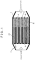
- FIG. 1 is a longitudinal cross-sectional diagram of a particulate filter in which the invention is used
- FIG. 2 is a transversal cross-sectional diagram of a particulate filter in which the invention is used.
- a particulate filter 1 illustrated in FIGS. 1 and 2 is disposed in an exhaust gas passage of an internal combustion engine, and traps PM that is present in the exhaust gas of the internal combustion engine.
- a columnar base material 3 is provided in the interior of a cylindrical case 2 of the particulate filter 1.
- a plurality of passages 4, 5 that extend in the axial direction (direction of flow of the exhaust gas) is formed in the base material 3. These plurality of passages 4, 5 are disposed in the form of a honeycomb. In other words, the base material 3 is formed in such a way so as to define the plurality of passages 4, 5 that are disposed in the form of a honeycomb.
- the number of the passages 4, 5 illustrated in FIGS. 1 and 2 is merely exemplary, and may be established, as needed, in accordance with the specifications of the vehicle or the internal combustion engine.
- the upstream ends of the passages 4, in the flow direction of the exhaust gas are blocked with plugs 40.
- the downstream ends of the remaining passages 5, in the flow direction of the exhaust gas are blocked with plugs 50.
- the passages 4 and the passages 5 are disposed alternately.
- the passages 4 will be referred to as first passages 4, and the passages 5 as second passages 5.
- Sites (partition walls) 30 of the base material 3 that are positioned between the first passages 4 and the second passages 5 are formed of a porous body. Only the partition walls 30 of the base material 3 may be formed of a porous body; alternatively, the entirety of the base material 3 may be formed of a porous body.
- Conventional materials that are appropriate for trapping of PM in exhaust gas can be used herein as the material of the porous body.
- a ceramic is preferably used, as represented by, for instance, silicon carbide, silicon nitride, cordierite, zirconia, titania, alumina, silica, mullite, lithium aluminum silicate, and zirconium phosphate.
- the partition walls 30 are shaped in such a manner that the average pore size of the pores formed on the partition walls 30 is greater than ash and ash aggregates. Specifically, the partition walls 30 are shaped in such a manner that the average pore ranges from 25 ⁇ m to 50 ⁇ m.
- 25 ⁇ m is the minimum value that allows the greater part of ash and ash aggregates to slip through
- 50 ⁇ m is the minimum value of pore size that is deemed to compromise the strength and durability of the base material 3.
- a porous coat layer 300 is provided on the surface of the partition walls 30 that enclose the second passages 5.
- the coat layer 300 is provided at a region, of the partition walls 30, from the upstream end thereof in the flow direction of the exhaust gas up to a position before the downstream end. That is, the position of the upstream end of the coat layer 300 in the flow direction of the exhaust gas coincides with that of the upstream ends of the partition walls 30, but the downstream end of the coat layer 300 is positioned further toward the front (upstream) side than the downstream ends of the partition walls 30.
- the coat layer 300 is a solid-state dispersion in which substantially spherical particles 301 are homogeneously dispersed and layered, as illustrated in FIG. 3 .
- Gaps 302 become formed between particles 301 and particles 301, as illustrated in FIG. 4 in a case where the coat layer 300 is composed of such a dispersion. These gaps 302 function as pores for trapping PM.
- Particles of a ceramic identical to that of the base material 3 may be used as the particles 301 that make up the dispersion, but preferably there are used particles of a metal (for instance, a metal of the Pt group) having oxidizing ability.
- a metal for instance, a metal of the Pt group
- the dispersion is made of metal particles of the Pt group, the PM trapped in the gaps 302 is quickly oxidized and removed in a case where high-temperature exhaust gas, or exhaust gas having an unburned fuel component, flows into the particulate filter 1.
- the average particle size of the particles 301 that make up the dispersion ranges preferably from 1 ⁇ m to 10 ⁇ m. That is because the amount of PM that slips through the particulate filter 1 is large in a case where the average particle size of the particles is smaller than 1 ⁇ m, while the pressure loss in the particulate filter 1 is greater in a case where the average particle size is greater than 10 ⁇ m, as illustrated in FIG. 5 . Therefore, PM can be trapped, while suppressing increases in pressure loss, when the coat layer (dispersion) is made up of particles having an average particle size ranging from 1 ⁇ m to 10 ⁇ m.
- the passage cross-sectional area of the portion of the second passages 5 at which the coat layer 300 is provided is equal to the passage cross-sectional area of the portion at which the coat layer 300 is not provided. Accordingly, the thickness of the sites at which the coat layer 300 is provided may be smaller than the thickness of the sites at which the coat layer 300 is not provided, on the partition walls 30 that enclose the second passages 5, as illustrated in FIG. 3 described above.
- a diameter A1 of the second passages 5 at a portion where the coat layer 300 is to be provided may be set to be greater, in a state where the coat layer 300 is not provided on the second passages 5, than a diameter A2 of the second passages 5 at a portion where the coat layer 300 is not to be provided, as illustrated in FIG. 6 .
- the method for forming the coat layer 300 is not particularly limited, but, as an example, a method can be resorted to that involves coating the surface of the partition walls 30 with a slurry that includes metal particles of the Pt group, followed by drying and firing.
- a method can be resorted to that involves coating the surface of the partition walls 30 with a slurry that includes metal particles of the Pt group, followed by drying and firing.
- the average particle size of the metal particles (primary particles) be smaller than that of the particles 301 (secondary particles) after formation of the coat layer 300, and that the average particle size of the secondary particles lie in a range from 1 ⁇ m to 10 ⁇ m.
- the average particle size of the primary particles in the slurry is smaller than the average pore size of the partition walls 30 when the average pore size of the partition walls 30 is set to range from 25 ⁇ m to 50 ⁇ m and the average particle size of the particles 301 is set to range from 1 ⁇ m to 10 ⁇ m. Accordingly, primary particles may in some instances intrude into the pores of the partition walls 30 when the partition walls 30 are coated with the slurry. When drying and/or firing is performed in a state where primary particles have intruded into the pores of the partition walls 30, the pore size of the partition walls 30 may decrease, and the pores of the partition walls 30 may become blocked. The pressure loss in the particulate filter 1 may increase unnecessarily in such a case.
- the coat layer 300 is preferably formed by resorting to a method that involves applying the slurry after the pores of the partition walls 30 have been filled with a substance that burns off in a drying process or a firing process, a method that involves hydrophobizing the partition walls 30, and using a liquid that has water or a water-soluble organic matter as a medium liquid of the slurry, or a method that involves causing a volatile solvent to be held in the pores of the partition walls 30, and applying thereafter the slurry having the volatile solvent as a main dispersion medium.
- the exhaust gas that flows into the particulate filter 1 flows firstly into the second passages 5.
- the exhaust gas that has flowed into the second passages 5 flows then into the first passages 4 via the gaps 302 of the coat layer 300 and the pores of the partition walls 30.
- most of the PM in the exhaust gas becomes trapped in the coat layer 300.
- the ash in the exhaust gas and the ash that is formed in the second passages 5 flow into the first passages 4 via the pores of the region (region in the vicinity of the downstream end) of the partition walls 30 at which the coat layer 300 is not provided.
- the exhaust gas and ash that have flowed into the first passages 4 are discharged downstream of the particulate filter 1, through the openings at the downstream ends of the first passages 4.
- FIG. 7 to FIG. 8 A second working example of the invention will be explained next on the basis of FIG. 7 to FIG. 8 .
- Features that are different from those of the first working example described above will be explained herein, while explanation of identical features will be omitted.
- the first working example described above and the working example differ in that now the coat layer 300 has a metal the ionization tendency is greater than that of Ca.
- ash is generated and becomes deposited readily on the partition walls 30 in the vicinity of the downstream ends of the second passages 5, i.e. at the portions of the partition walls 30 at which the coat layer 300 is not provided.
- a small amount of ash may be generated at the partition walls 30 in the vicinity of the upstream ends of the second passages 5 i.e. at portions where the coat layer 300 is provided on the partition walls 30. Accordingly, ash may become deposited on the coat layer 300, and the gaps 302 of the coat layer 300 may become blocked, when the usage time of the particulate filter 1 is prolonged.
- the coat layer 300 has a metal, the ionization tendency of which, is greater than that of the main component of the ash, by contrast, other components in the exhaust gas are adsorbed to or taken up into the coat layer 300 in preference to that main component. As a result, the main component of the ash does not bond readily to other components in the exhaust gas at the surface of the coat layer 300. That is, generation of ash at the surface of the coat layer 300 is suppressed.
- Ca is herein deemed to be the main component of the ash.
- the coat layer 300 includes a metal such as K, Ba or the like having a greater ionization tendency than that of Ca, then, S, P or the like in the exhaust gas bond to K or Ba in preference to Ca. As a result, ash such as CaSO 4 or Ca 3 (PO 4 ) 2 is not generated readily at the surface of the coat layer 300.
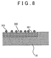
- a method for incorporating K or Ba into the coat layer 300 may involve for instance mixing, into the particles 301 that make up the coat layer 300, particles 303 of K or Ba having an average particle size identical to that of the particles 301, as illustrated in FIG. 7 . Particles 303 of K or Ba may be caused to be supported on the surface of the coat layer 300, as illustrated in FIG. 8 .
- the working example as described above allows suppressing yet more reliably generation and deposition of ash at the coat layer 300.
- the PM trapping capability of the coat layer 300 can be maintained over long periods of time.
- the coat layer 300 has a metal, the ionization tendency of which, is greater than that of Ca, but the coat layer 300 may be set to have a metal, the ionization tendency of which, is greater than that of magnesium (Mg); alternatively, the coat layer 300 may be set to have both a metal, the ionization tendency of which, is greater than that of Ca and a metal, the ionization tendency of which, is greater than that of Mg.
- Mg magnesium
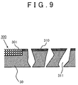
- FIG. 9 A third working example of the invention will be explained next on the basis of FIG. 9 to FIG. 10 .
- Features that are different from those of the first working example described above will be explained herein, while explanation of identical features will be omitted.
- the first working example described above and the working example differ in that herein a metal having oxidizing ability is supported at those regions, of the partition walls 30 that enclose the second passages 5, where the coat layer 300 is not provided.
- the greater part of the PM that flows into the particulate filter 1 (second passages 5) is trapped in the pores of the coat layer 300 at the region that extends from the upstream end up to the front of the downstream ends of the second passages 5.
- a small amount of PM may reach the partition walls 30 in the vicinity of the downstream ends of the second passages 5 (i.e. the portions of the partition walls 30 at which the coat layer 300 is not provided). In this case, a small amount of PM may slip through the pores of the partition walls 30 and flow out of the particulate filter 1.
- Methods that can be resorted to for causing the metal having oxidizing ability to be supported at a region of the partition walls 30 at which the coat layer 300 is not provided may involve, for instance, providing a coat layer that has metal particles of the Pt group, typified by Pt (hereafter referred to as "catalyst coat layer”) 310 on the surface of the partition walls 30, as illustrated in FIG. 9 .
- a method may also be resorted to wherein a catalyst coat layer 310 is provided also on the inner wall surface of pores 311 of the partition walls 30, in addition to on the surface of the partition walls 30, as illustrated in FIG. 10 .
- the average pore size of the partition walls 30 and the thickness of the catalyst coat layer 310 are established in such a manner that the average pore size after the catalyst coat layer 310 has been provided ranges from 25 ⁇ m to 50 ⁇ m.
- the catalyst coat layer 310 described in the working example may be provided only on the partition walls 30 at the portion where the coat layer 300 is not provided, or may be provided over the entirety of the partition walls 30.
- the PM that is not trapped in the coat layer 300 from among the PM that flows into the particulate filter 1 (i.e. the PM that flows into the second passages 5), is oxidized at the partition walls 30 in the vicinity of the downstream ends of the second passages 5. As a result, it becomes possible to keep down the amount of PM that slips through the particulate filter 1 yet smaller.
- a metal having a greater ionization tendency than that of the main component of the ash may be incorporated into the coat layer 300, and a metal having oxidizing ability may be caused to be supported on the partition walls 30, at a region at which the coat layer 300 is not provided.
- generation and deposition of ash at the coat layer 300 can be suppressed yet more reliably while suppressing slipping of PM through the partition walls 30 at portions where the coat layer 300 is not provided.
- the thickness of the coat layer 300 is substantially constant in the flow direction of the exhaust gas, but the thickness upstream may be set to be greater than the thickness downstream.
- the thickness of the coat layer 300 may be set to decrease gradually from the upstream side towards the downstream side, as illustrated in FIG. 11 .
- the PM in the exhaust gas is trapped more readily at sites, in the coat layer 300, that lie close to the upstream end than at sites distant therefrom. Accordingly, most of the PM in the exhaust gas can be trapped even if the thickness of the coat layer 300 decreases from the upstream side towards the downstream side. Further, pressure loss is smaller when the thickness of the coat layer 300 on the downstream side is smaller. It becomes thus possible to keep to a minimum increases in pressure loss caused by coat layer 300.
- the coat layer 300 is provided only on the partition walls 30 that enclose the second passages 5, but the coat layer 300 may be provided also on the partition walls 30 that enclose the first passages 4.
- pressure loss in the particulate filter 1 may increase significantly when the coat layer 300 is provided on both the partition walls 30 that enclose the second passages 5 and the partition walls 30 that enclose the first passages 4.
- the coat layer 300 may be provided at both partition walls 30, so long as the pressure loss in the particulate filter 1 lies within an allowable range.
Landscapes
- Engineering & Computer Science (AREA)
- Chemical & Material Sciences (AREA)
- Chemical Kinetics & Catalysis (AREA)
- Physics & Mathematics (AREA)
- Geometry (AREA)
- Mechanical Engineering (AREA)
- Combustion & Propulsion (AREA)
- General Engineering & Computer Science (AREA)
- Processes For Solid Components From Exhaust (AREA)
- Filtering Materials (AREA)
- Filtering Of Dispersed Particles In Gases (AREA)
- Catalysts (AREA)
- Exhaust Gas After Treatment (AREA)
Applications Claiming Priority (1)
| Application Number | Priority Date | Filing Date | Title |
|---|---|---|---|
| PCT/JP2012/058620 WO2013145266A1 (ja) | 2012-03-30 | 2012-03-30 | パティキュレートフィルタ |
Publications (3)
| Publication Number | Publication Date |
|---|---|
| EP2832962A1 EP2832962A1 (en) | 2015-02-04 |
| EP2832962A4 EP2832962A4 (en) | 2015-05-20 |
| EP2832962B1 true EP2832962B1 (en) | 2016-08-17 |
Family
ID=49258630
Family Applications (1)
| Application Number | Title | Priority Date | Filing Date |
|---|---|---|---|
| EP12872470.5A Not-in-force EP2832962B1 (en) | 2012-03-30 | 2012-03-30 | Particulate filter |
Country Status (9)
| Country | Link |
|---|---|
| US (1) | US9394816B2 (ja) |
| EP (1) | EP2832962B1 (ja) |
| JP (1) | JP5787031B2 (ja) |
| KR (1) | KR20140131964A (ja) |
| CN (1) | CN104204433B (ja) |
| AU (1) | AU2012374854B2 (ja) |
| BR (1) | BR112014024072B8 (ja) |
| IN (1) | IN2014DN08076A (ja) |
| WO (1) | WO2013145266A1 (ja) |
Families Citing this family (22)
| Publication number | Priority date | Publication date | Assignee | Title |
|---|---|---|---|---|
| US9669359B2 (en) * | 2012-07-06 | 2017-06-06 | Denso International America, Inc. | Catalytic converter substrate |
| WO2014076767A1 (ja) * | 2012-11-13 | 2014-05-22 | トヨタ自動車株式会社 | 内燃機関の排気浄化装置 |
| US9718026B2 (en) | 2012-11-28 | 2017-08-01 | Toyota Jidosha Kabushiki Kaisha | Exhaust gas purification filter |
| WO2014087472A1 (ja) * | 2012-12-03 | 2014-06-12 | トヨタ自動車株式会社 | 排気浄化フィルタ |
| JP6007864B2 (ja) * | 2013-06-10 | 2016-10-12 | トヨタ自動車株式会社 | 排気浄化フィルタ |
| JP6028710B2 (ja) * | 2013-10-22 | 2016-11-16 | トヨタ自動車株式会社 | 内燃機関の排気浄化装置 |
| RU2664036C2 (ru) * | 2013-12-25 | 2018-08-14 | Федеральное государственное унитарное предприятие "Центральный ордена Трудового Красного Знамени научно-исследовательский автомобильный и автомоторный институт "НАМИ" | Фильтрующий элемент для улавливания твердых частиц |
| JP6690379B2 (ja) * | 2016-04-14 | 2020-04-28 | いすゞ自動車株式会社 | Pmセンサ |
| CN105833620A (zh) * | 2016-04-22 | 2016-08-10 | 南京柯瑞特种陶瓷股份有限公司 | 一种半通式蜂窝陶瓷颗粒物过滤器及其制备方法 |
| JP6605522B2 (ja) | 2017-03-09 | 2019-11-13 | 株式会社キャタラー | 排ガス浄化用触媒 |
| WO2019065741A1 (ja) * | 2017-09-27 | 2019-04-04 | 三井金属鉱業株式会社 | パティキュレートフィルタ |
| EP3501647A1 (de) * | 2017-12-19 | 2019-06-26 | Umicore Ag & Co. Kg | Katalytisch aktives partikelfilter |
| EP3505245B1 (de) | 2017-12-19 | 2019-10-23 | Umicore Ag & Co. Kg | Katalytisch aktives partikelfilter |
| EP3501648B1 (de) | 2017-12-19 | 2023-10-04 | Umicore Ag & Co. Kg | Katalytisch aktives partikelfilter |
| JP7049155B2 (ja) * | 2018-03-30 | 2022-04-06 | 日本碍子株式会社 | ハニカムフィルタ |
| JP7037985B2 (ja) * | 2018-03-30 | 2022-03-17 | 日本碍子株式会社 | ハニカムフィルタ |
| JP7097210B2 (ja) * | 2018-03-30 | 2022-07-07 | 日本碍子株式会社 | ハニカムフィルタ |
| JP7243972B2 (ja) * | 2018-09-11 | 2023-03-22 | 株式会社キャタラー | ファインバブルの製造装置及びファインバブルの製造方法 |
| JP6712732B2 (ja) * | 2018-09-11 | 2020-06-24 | 株式会社キャタラー | ファインバブルを用いた反応装置及び反応方法 |
| DE102018127953A1 (de) | 2018-11-08 | 2020-05-14 | Umicore Ag & Co. Kg | Wandflussfilter mit hoher Filtrationseffizienz |
| DE102018127955A1 (de) | 2018-11-08 | 2020-05-14 | Umicore Ag & Co. Kg | Katalytisch aktiver Partikelfilter mit hoher Filtrationseffizienz |
| JP7271610B2 (ja) * | 2021-06-17 | 2023-05-11 | 株式会社キャタラー | パティキュレートフィルタ |
Family Cites Families (18)
| Publication number | Priority date | Publication date | Assignee | Title |
|---|---|---|---|---|
| JP3344371B2 (ja) | 1999-06-23 | 2002-11-11 | トヨタ自動車株式会社 | 内燃機関の排気浄化装置 |
| JP2002295228A (ja) * | 2001-03-30 | 2002-10-09 | Ibiden Co Ltd | 排気ガス浄化フィルタ |
| EP1829595A1 (en) * | 2002-03-29 | 2007-09-05 | Ibiden Co., Ltd. | Ceramic filter and exhaust gas decontamination unit |
| JP3874270B2 (ja) * | 2002-09-13 | 2007-01-31 | トヨタ自動車株式会社 | 排ガス浄化フィルタ触媒及びその製造方法 |
| JP4172986B2 (ja) | 2002-10-10 | 2008-10-29 | 日本碍子株式会社 | ハニカム構造体及びその製造方法並びに当該ハニカム構造体を用いた排ガス浄化システム |
| JP2004239199A (ja) * | 2003-02-07 | 2004-08-26 | Hino Motors Ltd | パティキュレートフィルタ |
| JP2004251245A (ja) | 2003-02-21 | 2004-09-09 | Toyota Motor Corp | 触媒付きフィルタ及びそのフィルタを用いた排気浄化装置 |
| ZA200600757B (en) * | 2003-08-29 | 2007-05-30 | Dow Global Technologies Inc | Improved diesel exhaust filter |
| JP2005305417A (ja) * | 2004-03-26 | 2005-11-04 | Ngk Insulators Ltd | 触媒機能を有するハニカムフィルタとその製造方法 |
| JP4926868B2 (ja) | 2007-02-09 | 2012-05-09 | イビデン株式会社 | ハニカム構造体および排気ガス処理装置 |
| JP5063604B2 (ja) | 2007-03-30 | 2012-10-31 | イビデン株式会社 | ハニカムフィルタ |
| JP4845795B2 (ja) * | 2007-04-09 | 2011-12-28 | トヨタ自動車株式会社 | 排ガス浄化フィルタとその製造方法 |
| EP2065575B1 (en) * | 2007-11-29 | 2012-08-15 | Corning Incorporated | Wall-flow honeycomb filter having high-storage capacity and low backpressure |
| JP5208886B2 (ja) * | 2008-09-03 | 2013-06-12 | 日本碍子株式会社 | 触媒担持フィルタ |
| JP5349108B2 (ja) * | 2009-03-26 | 2013-11-20 | 日本碍子株式会社 | ハニカムフィルタ |
| FR2944052B1 (fr) * | 2009-04-03 | 2011-04-22 | Saint Gobain Ct Recherches | Structure de filtration d'un gaz et de reduction des nox. |
| EP2556872B1 (en) * | 2010-03-31 | 2019-05-15 | NGK Insulators, Ltd. | Honeycomb filter |
| EP2556871B1 (en) * | 2010-03-31 | 2016-09-07 | NGK Insulators, Ltd. | Honeycomb filter |
-
2012
- 2012-03-30 JP JP2014507228A patent/JP5787031B2/ja not_active Expired - Fee Related
- 2012-03-30 IN IN8076DEN2014 patent/IN2014DN08076A/en unknown
- 2012-03-30 AU AU2012374854A patent/AU2012374854B2/en not_active Ceased
- 2012-03-30 US US14/388,315 patent/US9394816B2/en active Active
- 2012-03-30 WO PCT/JP2012/058620 patent/WO2013145266A1/ja active Application Filing
- 2012-03-30 CN CN201280072115.0A patent/CN104204433B/zh not_active Expired - Fee Related
- 2012-03-30 KR KR1020147025869A patent/KR20140131964A/ko not_active Application Discontinuation
- 2012-03-30 EP EP12872470.5A patent/EP2832962B1/en not_active Not-in-force
- 2012-03-30 BR BR112014024072A patent/BR112014024072B8/pt not_active IP Right Cessation
Also Published As
| Publication number | Publication date |
|---|---|
| BR112014024072B1 (pt) | 2021-05-04 |
| AU2012374854A1 (en) | 2014-10-16 |
| IN2014DN08076A (ja) | 2015-05-01 |
| EP2832962A1 (en) | 2015-02-04 |
| CN104204433A (zh) | 2014-12-10 |
| EP2832962A4 (en) | 2015-05-20 |
| WO2013145266A1 (ja) | 2013-10-03 |
| KR20140131964A (ko) | 2014-11-14 |
| BR112014024072B8 (pt) | 2022-03-15 |
| US20150059321A1 (en) | 2015-03-05 |
| CN104204433B (zh) | 2016-08-31 |
| AU2012374854B2 (en) | 2016-05-12 |
| JPWO2013145266A1 (ja) | 2015-08-03 |
| US9394816B2 (en) | 2016-07-19 |
| JP5787031B2 (ja) | 2015-09-30 |
Similar Documents
| Publication | Publication Date | Title |
|---|---|---|
| EP2832962B1 (en) | Particulate filter | |
| US7578864B2 (en) | Ceramic honeycomb filter and its production method | |
| KR100944133B1 (ko) | 허니컴 필터 | |
| EP1375849B1 (en) | Ceramic honeycomb filter | |
| US20050011186A1 (en) | Exhaust gas cleaner for internal combustion engine with particulate filter having heat-absorbing area | |
| US10294838B2 (en) | Exhaust purification filter | |
| US10625195B2 (en) | Honeycomb filter | |
| JP6007864B2 (ja) | 排気浄化フィルタ | |
| JP5975111B2 (ja) | 排気浄化フィルタ | |
| US11421570B2 (en) | Particulate filter and canning structure | |
| US10525394B2 (en) | Honeycomb filter | |
| JP5869407B2 (ja) | 複合ハニカム構造体 | |
| JP2006000685A (ja) | ハニカム構造体及びその製造方法 | |
| RU2575520C1 (ru) | Фильтр для твердых частиц | |
| CN111749761A (zh) | 蜂窝过滤器 | |
| JP6314783B2 (ja) | 排ガス浄化フィルタ |
Legal Events
| Date | Code | Title | Description |
|---|---|---|---|
| PUAI | Public reference made under article 153(3) epc to a published international application that has entered the european phase |
Free format text: ORIGINAL CODE: 0009012 |
|
| 17P | Request for examination filed |
Effective date: 20140926 |
|
| AK | Designated contracting states |
Kind code of ref document: A1 Designated state(s): AL AT BE BG CH CY CZ DE DK EE ES FI FR GB GR HR HU IE IS IT LI LT LU LV MC MK MT NL NO PL PT RO RS SE SI SK SM TR |
|
| AX | Request for extension of the european patent |
Extension state: BA ME |
|
| RA4 | Supplementary search report drawn up and despatched (corrected) |
Effective date: 20150421 |
|
| RIC1 | Information provided on ipc code assigned before grant |
Ipc: F01N 3/02 20060101ALI20150415BHEP Ipc: F01N 3/023 20060101ALI20150415BHEP Ipc: B01D 46/24 20060101ALI20150415BHEP Ipc: F01N 3/022 20060101AFI20150415BHEP Ipc: F01N 3/035 20060101ALI20150415BHEP |
|
| DAX | Request for extension of the european patent (deleted) | ||
| GRAP | Despatch of communication of intention to grant a patent |
Free format text: ORIGINAL CODE: EPIDOSNIGR1 |
|
| INTG | Intention to grant announced |
Effective date: 20160309 |
|
| GRAS | Grant fee paid |
Free format text: ORIGINAL CODE: EPIDOSNIGR3 |
|
| GRAA | (expected) grant |
Free format text: ORIGINAL CODE: 0009210 |
|
| AK | Designated contracting states |
Kind code of ref document: B1 Designated state(s): AL AT BE BG CH CY CZ DE DK EE ES FI FR GB GR HR HU IE IS IT LI LT LU LV MC MK MT NL NO PL PT RO RS SE SI SK SM TR |
|
| REG | Reference to a national code |
Ref country code: GB Ref legal event code: FG4D |
|
| REG | Reference to a national code |
Ref country code: CH Ref legal event code: EP |
|
| REG | Reference to a national code |
Ref country code: IE Ref legal event code: FG4D |
|
| REG | Reference to a national code |
Ref country code: AT Ref legal event code: REF Ref document number: 821320 Country of ref document: AT Kind code of ref document: T Effective date: 20160915 |
|
| REG | Reference to a national code |
Ref country code: DE Ref legal event code: R096 Ref document number: 602012022071 Country of ref document: DE |
|
| REG | Reference to a national code |
Ref country code: NL Ref legal event code: MP Effective date: 20160817 |
|
| REG | Reference to a national code |
Ref country code: DE Ref legal event code: R084 Ref document number: 602012022071 Country of ref document: DE |
|
| REG | Reference to a national code |
Ref country code: LT Ref legal event code: MG4D |
|
| REG | Reference to a national code |
Ref country code: AT Ref legal event code: MK05 Ref document number: 821320 Country of ref document: AT Kind code of ref document: T Effective date: 20160817 |
|
| REG | Reference to a national code |
Ref country code: GB Ref legal event code: 746 Effective date: 20161228 |
|
| PG25 | Lapsed in a contracting state [announced via postgrant information from national office to epo] |
Ref country code: RS Free format text: LAPSE BECAUSE OF FAILURE TO SUBMIT A TRANSLATION OF THE DESCRIPTION OR TO PAY THE FEE WITHIN THE PRESCRIBED TIME-LIMIT Effective date: 20160817 Ref country code: HR Free format text: LAPSE BECAUSE OF FAILURE TO SUBMIT A TRANSLATION OF THE DESCRIPTION OR TO PAY THE FEE WITHIN THE PRESCRIBED TIME-LIMIT Effective date: 20160817 Ref country code: FI Free format text: LAPSE BECAUSE OF FAILURE TO SUBMIT A TRANSLATION OF THE DESCRIPTION OR TO PAY THE FEE WITHIN THE PRESCRIBED TIME-LIMIT Effective date: 20160817 Ref country code: LT Free format text: LAPSE BECAUSE OF FAILURE TO SUBMIT A TRANSLATION OF THE DESCRIPTION OR TO PAY THE FEE WITHIN THE PRESCRIBED TIME-LIMIT Effective date: 20160817 Ref country code: NO Free format text: LAPSE BECAUSE OF FAILURE TO SUBMIT A TRANSLATION OF THE DESCRIPTION OR TO PAY THE FEE WITHIN THE PRESCRIBED TIME-LIMIT Effective date: 20161117 Ref country code: IT Free format text: LAPSE BECAUSE OF FAILURE TO SUBMIT A TRANSLATION OF THE DESCRIPTION OR TO PAY THE FEE WITHIN THE PRESCRIBED TIME-LIMIT Effective date: 20160817 Ref country code: NL Free format text: LAPSE BECAUSE OF FAILURE TO SUBMIT A TRANSLATION OF THE DESCRIPTION OR TO PAY THE FEE WITHIN THE PRESCRIBED TIME-LIMIT Effective date: 20160817 |
|
| REG | Reference to a national code |
Ref country code: FR Ref legal event code: PLFP Year of fee payment: 6 |
|
| PG25 | Lapsed in a contracting state [announced via postgrant information from national office to epo] |
Ref country code: GR Free format text: LAPSE BECAUSE OF FAILURE TO SUBMIT A TRANSLATION OF THE DESCRIPTION OR TO PAY THE FEE WITHIN THE PRESCRIBED TIME-LIMIT Effective date: 20161118 Ref country code: SE Free format text: LAPSE BECAUSE OF FAILURE TO SUBMIT A TRANSLATION OF THE DESCRIPTION OR TO PAY THE FEE WITHIN THE PRESCRIBED TIME-LIMIT Effective date: 20160817 Ref country code: PT Free format text: LAPSE BECAUSE OF FAILURE TO SUBMIT A TRANSLATION OF THE DESCRIPTION OR TO PAY THE FEE WITHIN THE PRESCRIBED TIME-LIMIT Effective date: 20161219 Ref country code: PL Free format text: LAPSE BECAUSE OF FAILURE TO SUBMIT A TRANSLATION OF THE DESCRIPTION OR TO PAY THE FEE WITHIN THE PRESCRIBED TIME-LIMIT Effective date: 20160817 Ref country code: ES Free format text: LAPSE BECAUSE OF FAILURE TO SUBMIT A TRANSLATION OF THE DESCRIPTION OR TO PAY THE FEE WITHIN THE PRESCRIBED TIME-LIMIT Effective date: 20160817 Ref country code: LV Free format text: LAPSE BECAUSE OF FAILURE TO SUBMIT A TRANSLATION OF THE DESCRIPTION OR TO PAY THE FEE WITHIN THE PRESCRIBED TIME-LIMIT Effective date: 20160817 Ref country code: AT Free format text: LAPSE BECAUSE OF FAILURE TO SUBMIT A TRANSLATION OF THE DESCRIPTION OR TO PAY THE FEE WITHIN THE PRESCRIBED TIME-LIMIT Effective date: 20160817 |
|
| PG25 | Lapsed in a contracting state [announced via postgrant information from national office to epo] |
Ref country code: RO Free format text: LAPSE BECAUSE OF FAILURE TO SUBMIT A TRANSLATION OF THE DESCRIPTION OR TO PAY THE FEE WITHIN THE PRESCRIBED TIME-LIMIT Effective date: 20160817 Ref country code: EE Free format text: LAPSE BECAUSE OF FAILURE TO SUBMIT A TRANSLATION OF THE DESCRIPTION OR TO PAY THE FEE WITHIN THE PRESCRIBED TIME-LIMIT Effective date: 20160817 |
|
| REG | Reference to a national code |
Ref country code: DE Ref legal event code: R097 Ref document number: 602012022071 Country of ref document: DE |
|
| PG25 | Lapsed in a contracting state [announced via postgrant information from national office to epo] |
Ref country code: BG Free format text: LAPSE BECAUSE OF FAILURE TO SUBMIT A TRANSLATION OF THE DESCRIPTION OR TO PAY THE FEE WITHIN THE PRESCRIBED TIME-LIMIT Effective date: 20161117 Ref country code: CZ Free format text: LAPSE BECAUSE OF FAILURE TO SUBMIT A TRANSLATION OF THE DESCRIPTION OR TO PAY THE FEE WITHIN THE PRESCRIBED TIME-LIMIT Effective date: 20160817 Ref country code: DK Free format text: LAPSE BECAUSE OF FAILURE TO SUBMIT A TRANSLATION OF THE DESCRIPTION OR TO PAY THE FEE WITHIN THE PRESCRIBED TIME-LIMIT Effective date: 20160817 Ref country code: SM Free format text: LAPSE BECAUSE OF FAILURE TO SUBMIT A TRANSLATION OF THE DESCRIPTION OR TO PAY THE FEE WITHIN THE PRESCRIBED TIME-LIMIT Effective date: 20160817 Ref country code: SK Free format text: LAPSE BECAUSE OF FAILURE TO SUBMIT A TRANSLATION OF THE DESCRIPTION OR TO PAY THE FEE WITHIN THE PRESCRIBED TIME-LIMIT Effective date: 20160817 Ref country code: BE Free format text: LAPSE BECAUSE OF FAILURE TO SUBMIT A TRANSLATION OF THE DESCRIPTION OR TO PAY THE FEE WITHIN THE PRESCRIBED TIME-LIMIT Effective date: 20160817 |
|
| PLBE | No opposition filed within time limit |
Free format text: ORIGINAL CODE: 0009261 |
|
| STAA | Information on the status of an ep patent application or granted ep patent |
Free format text: STATUS: NO OPPOSITION FILED WITHIN TIME LIMIT |
|
| 26N | No opposition filed |
Effective date: 20170518 |
|
| PG25 | Lapsed in a contracting state [announced via postgrant information from national office to epo] |
Ref country code: SI Free format text: LAPSE BECAUSE OF FAILURE TO SUBMIT A TRANSLATION OF THE DESCRIPTION OR TO PAY THE FEE WITHIN THE PRESCRIBED TIME-LIMIT Effective date: 20160817 |
|
| REG | Reference to a national code |
Ref country code: CH Ref legal event code: PL |
|
| PG25 | Lapsed in a contracting state [announced via postgrant information from national office to epo] |
Ref country code: MC Free format text: LAPSE BECAUSE OF FAILURE TO SUBMIT A TRANSLATION OF THE DESCRIPTION OR TO PAY THE FEE WITHIN THE PRESCRIBED TIME-LIMIT Effective date: 20160817 |
|
| REG | Reference to a national code |
Ref country code: IE Ref legal event code: MM4A |
|
| PG25 | Lapsed in a contracting state [announced via postgrant information from national office to epo] |
Ref country code: LU Free format text: LAPSE BECAUSE OF NON-PAYMENT OF DUE FEES Effective date: 20170330 |
|
| REG | Reference to a national code |
Ref country code: FR Ref legal event code: PLFP Year of fee payment: 7 |
|
| PG25 | Lapsed in a contracting state [announced via postgrant information from national office to epo] |
Ref country code: LI Free format text: LAPSE BECAUSE OF NON-PAYMENT OF DUE FEES Effective date: 20170331 Ref country code: CH Free format text: LAPSE BECAUSE OF NON-PAYMENT OF DUE FEES Effective date: 20170331 Ref country code: IE Free format text: LAPSE BECAUSE OF NON-PAYMENT OF DUE FEES Effective date: 20170330 |
|
| PG25 | Lapsed in a contracting state [announced via postgrant information from national office to epo] |
Ref country code: MT Free format text: LAPSE BECAUSE OF NON-PAYMENT OF DUE FEES Effective date: 20170330 |
|
| PG25 | Lapsed in a contracting state [announced via postgrant information from national office to epo] |
Ref country code: AL Free format text: LAPSE BECAUSE OF FAILURE TO SUBMIT A TRANSLATION OF THE DESCRIPTION OR TO PAY THE FEE WITHIN THE PRESCRIBED TIME-LIMIT Effective date: 20160817 |
|
| PG25 | Lapsed in a contracting state [announced via postgrant information from national office to epo] |
Ref country code: HU Free format text: LAPSE BECAUSE OF FAILURE TO SUBMIT A TRANSLATION OF THE DESCRIPTION OR TO PAY THE FEE WITHIN THE PRESCRIBED TIME-LIMIT; INVALID AB INITIO Effective date: 20120330 |
|
| PG25 | Lapsed in a contracting state [announced via postgrant information from national office to epo] |
Ref country code: CY Free format text: LAPSE BECAUSE OF FAILURE TO SUBMIT A TRANSLATION OF THE DESCRIPTION OR TO PAY THE FEE WITHIN THE PRESCRIBED TIME-LIMIT Effective date: 20160817 |
|
| PG25 | Lapsed in a contracting state [announced via postgrant information from national office to epo] |
Ref country code: MK Free format text: LAPSE BECAUSE OF FAILURE TO SUBMIT A TRANSLATION OF THE DESCRIPTION OR TO PAY THE FEE WITHIN THE PRESCRIBED TIME-LIMIT Effective date: 20160817 |
|
| PG25 | Lapsed in a contracting state [announced via postgrant information from national office to epo] |
Ref country code: TR Free format text: LAPSE BECAUSE OF FAILURE TO SUBMIT A TRANSLATION OF THE DESCRIPTION OR TO PAY THE FEE WITHIN THE PRESCRIBED TIME-LIMIT Effective date: 20160817 |
|
| PG25 | Lapsed in a contracting state [announced via postgrant information from national office to epo] |
Ref country code: IS Free format text: LAPSE BECAUSE OF FAILURE TO SUBMIT A TRANSLATION OF THE DESCRIPTION OR TO PAY THE FEE WITHIN THE PRESCRIBED TIME-LIMIT Effective date: 20161217 |
|
| PGFP | Annual fee paid to national office [announced via postgrant information from national office to epo] |
Ref country code: GB Payment date: 20220203 Year of fee payment: 11 Ref country code: DE Payment date: 20220203 Year of fee payment: 11 |
|
| PGFP | Annual fee paid to national office [announced via postgrant information from national office to epo] |
Ref country code: FR Payment date: 20220209 Year of fee payment: 11 |
|
| P01 | Opt-out of the competence of the unified patent court (upc) registered |
Effective date: 20230427 |
|
| REG | Reference to a national code |
Ref country code: DE Ref legal event code: R119 Ref document number: 602012022071 Country of ref document: DE |
|
| GBPC | Gb: european patent ceased through non-payment of renewal fee |
Effective date: 20230330 |
|
| PG25 | Lapsed in a contracting state [announced via postgrant information from national office to epo] |
Ref country code: GB Free format text: LAPSE BECAUSE OF NON-PAYMENT OF DUE FEES Effective date: 20230330 |
|
| PG25 | Lapsed in a contracting state [announced via postgrant information from national office to epo] |
Ref country code: GB Free format text: LAPSE BECAUSE OF NON-PAYMENT OF DUE FEES Effective date: 20230330 Ref country code: FR Free format text: LAPSE BECAUSE OF NON-PAYMENT OF DUE FEES Effective date: 20230331 Ref country code: DE Free format text: LAPSE BECAUSE OF NON-PAYMENT OF DUE FEES Effective date: 20231003 |