EP2832339A1 - Vorrichtung zum Herstellen einer Lösung, insbesondere in/an einer Dialysemaschine - Google Patents
Vorrichtung zum Herstellen einer Lösung, insbesondere in/an einer Dialysemaschine Download PDFInfo
- Publication number
- EP2832339A1 EP2832339A1 EP14178790.3A EP14178790A EP2832339A1 EP 2832339 A1 EP2832339 A1 EP 2832339A1 EP 14178790 A EP14178790 A EP 14178790A EP 2832339 A1 EP2832339 A1 EP 2832339A1
- Authority
- EP
- European Patent Office
- Prior art keywords
- cavity
- support element
- outlet
- inlet
- outer shell
- Prior art date
- Legal status (The legal status is an assumption and is not a legal conclusion. Google has not performed a legal analysis and makes no representation as to the accuracy of the status listed.)
- Granted
Links
Images


Classifications
-
- A—HUMAN NECESSITIES
- A61—MEDICAL OR VETERINARY SCIENCE; HYGIENE
- A61M—DEVICES FOR INTRODUCING MEDIA INTO, OR ONTO, THE BODY; DEVICES FOR TRANSDUCING BODY MEDIA OR FOR TAKING MEDIA FROM THE BODY; DEVICES FOR PRODUCING OR ENDING SLEEP OR STUPOR
- A61M1/00—Suction or pumping devices for medical purposes; Devices for carrying-off, for treatment of, or for carrying-over, body-liquids; Drainage systems
- A61M1/14—Dialysis systems; Artificial kidneys; Blood oxygenators ; Reciprocating systems for treatment of body fluids, e.g. single needle systems for hemofiltration or pheresis
-
- B—PERFORMING OPERATIONS; TRANSPORTING
- B01—PHYSICAL OR CHEMICAL PROCESSES OR APPARATUS IN GENERAL
- B01F—MIXING, e.g. DISSOLVING, EMULSIFYING OR DISPERSING
- B01F35/00—Accessories for mixers; Auxiliary operations or auxiliary devices; Parts or details of general application
- B01F35/50—Mixing receptacles
- B01F35/513—Flexible receptacles, e.g. bags supported by rigid containers
-
- A—HUMAN NECESSITIES
- A61—MEDICAL OR VETERINARY SCIENCE; HYGIENE
- A61M—DEVICES FOR INTRODUCING MEDIA INTO, OR ONTO, THE BODY; DEVICES FOR TRANSDUCING BODY MEDIA OR FOR TAKING MEDIA FROM THE BODY; DEVICES FOR PRODUCING OR ENDING SLEEP OR STUPOR
- A61M1/00—Suction or pumping devices for medical purposes; Devices for carrying-off, for treatment of, or for carrying-over, body-liquids; Drainage systems
- A61M1/14—Dialysis systems; Artificial kidneys; Blood oxygenators ; Reciprocating systems for treatment of body fluids, e.g. single needle systems for hemofiltration or pheresis
- A61M1/16—Dialysis systems; Artificial kidneys; Blood oxygenators ; Reciprocating systems for treatment of body fluids, e.g. single needle systems for hemofiltration or pheresis with membranes
- A61M1/1654—Dialysates therefor
- A61M1/1656—Apparatus for preparing dialysates
-
- A—HUMAN NECESSITIES
- A61—MEDICAL OR VETERINARY SCIENCE; HYGIENE
- A61M—DEVICES FOR INTRODUCING MEDIA INTO, OR ONTO, THE BODY; DEVICES FOR TRANSDUCING BODY MEDIA OR FOR TAKING MEDIA FROM THE BODY; DEVICES FOR PRODUCING OR ENDING SLEEP OR STUPOR
- A61M1/00—Suction or pumping devices for medical purposes; Devices for carrying-off, for treatment of, or for carrying-over, body-liquids; Drainage systems
- A61M1/14—Dialysis systems; Artificial kidneys; Blood oxygenators ; Reciprocating systems for treatment of body fluids, e.g. single needle systems for hemofiltration or pheresis
- A61M1/16—Dialysis systems; Artificial kidneys; Blood oxygenators ; Reciprocating systems for treatment of body fluids, e.g. single needle systems for hemofiltration or pheresis with membranes
- A61M1/1654—Dialysates therefor
- A61M1/1656—Apparatus for preparing dialysates
- A61M1/1666—Apparatus for preparing dialysates by dissolving solids
-
- A—HUMAN NECESSITIES
- A61—MEDICAL OR VETERINARY SCIENCE; HYGIENE
- A61M—DEVICES FOR INTRODUCING MEDIA INTO, OR ONTO, THE BODY; DEVICES FOR TRANSDUCING BODY MEDIA OR FOR TAKING MEDIA FROM THE BODY; DEVICES FOR PRODUCING OR ENDING SLEEP OR STUPOR
- A61M1/00—Suction or pumping devices for medical purposes; Devices for carrying-off, for treatment of, or for carrying-over, body-liquids; Drainage systems
- A61M1/14—Dialysis systems; Artificial kidneys; Blood oxygenators ; Reciprocating systems for treatment of body fluids, e.g. single needle systems for hemofiltration or pheresis
- A61M1/16—Dialysis systems; Artificial kidneys; Blood oxygenators ; Reciprocating systems for treatment of body fluids, e.g. single needle systems for hemofiltration or pheresis with membranes
- A61M1/1654—Dialysates therefor
- A61M1/1656—Apparatus for preparing dialysates
- A61M1/1668—Details of containers
-
- A—HUMAN NECESSITIES
- A61—MEDICAL OR VETERINARY SCIENCE; HYGIENE
- A61M—DEVICES FOR INTRODUCING MEDIA INTO, OR ONTO, THE BODY; DEVICES FOR TRANSDUCING BODY MEDIA OR FOR TAKING MEDIA FROM THE BODY; DEVICES FOR PRODUCING OR ENDING SLEEP OR STUPOR
- A61M1/00—Suction or pumping devices for medical purposes; Devices for carrying-off, for treatment of, or for carrying-over, body-liquids; Drainage systems
- A61M1/14—Dialysis systems; Artificial kidneys; Blood oxygenators ; Reciprocating systems for treatment of body fluids, e.g. single needle systems for hemofiltration or pheresis
- A61M1/16—Dialysis systems; Artificial kidneys; Blood oxygenators ; Reciprocating systems for treatment of body fluids, e.g. single needle systems for hemofiltration or pheresis with membranes
- A61M1/1654—Dialysates therefor
- A61M1/1656—Apparatus for preparing dialysates
- A61M1/1668—Details of containers
- A61M1/167—Flexible packaging for solid concentrates
-
- B—PERFORMING OPERATIONS; TRANSPORTING
- B65—CONVEYING; PACKING; STORING; HANDLING THIN OR FILAMENTARY MATERIAL
- B65D—CONTAINERS FOR STORAGE OR TRANSPORT OF ARTICLES OR MATERIALS, e.g. BAGS, BARRELS, BOTTLES, BOXES, CANS, CARTONS, CRATES, DRUMS, JARS, TANKS, HOPPERS, FORWARDING CONTAINERS; ACCESSORIES, CLOSURES, OR FITTINGS THEREFOR; PACKAGING ELEMENTS; PACKAGES
- B65D85/00—Containers, packaging elements or packages, specially adapted for particular articles or materials
- B65D85/70—Containers, packaging elements or packages, specially adapted for particular articles or materials for materials not otherwise provided for
- B65D85/804—Disposable containers or packages with contents which are mixed, infused or dissolved in situ, i.e. without having been previously removed from the package
- B65D85/8043—Packages adapted to allow liquid to pass through the contents
- B65D85/8049—Details of the inlet
-
- B—PERFORMING OPERATIONS; TRANSPORTING
- B65—CONVEYING; PACKING; STORING; HANDLING THIN OR FILAMENTARY MATERIAL
- B65D—CONTAINERS FOR STORAGE OR TRANSPORT OF ARTICLES OR MATERIALS, e.g. BAGS, BARRELS, BOTTLES, BOXES, CANS, CARTONS, CRATES, DRUMS, JARS, TANKS, HOPPERS, FORWARDING CONTAINERS; ACCESSORIES, CLOSURES, OR FITTINGS THEREFOR; PACKAGING ELEMENTS; PACKAGES
- B65D85/00—Containers, packaging elements or packages, specially adapted for particular articles or materials
- B65D85/70—Containers, packaging elements or packages, specially adapted for particular articles or materials for materials not otherwise provided for
- B65D85/804—Disposable containers or packages with contents which are mixed, infused or dissolved in situ, i.e. without having been previously removed from the package
- B65D85/8043—Packages adapted to allow liquid to pass through the contents
- B65D85/8052—Details of the outlet
-
- A—HUMAN NECESSITIES
- A61—MEDICAL OR VETERINARY SCIENCE; HYGIENE
- A61M—DEVICES FOR INTRODUCING MEDIA INTO, OR ONTO, THE BODY; DEVICES FOR TRANSDUCING BODY MEDIA OR FOR TAKING MEDIA FROM THE BODY; DEVICES FOR PRODUCING OR ENDING SLEEP OR STUPOR
- A61M2205/00—General characteristics of the apparatus
- A61M2205/75—General characteristics of the apparatus with filters
- A61M2205/7545—General characteristics of the apparatus with filters for solid matter, e.g. microaggregates
-
- A—HUMAN NECESSITIES
- A61—MEDICAL OR VETERINARY SCIENCE; HYGIENE
- A61M—DEVICES FOR INTRODUCING MEDIA INTO, OR ONTO, THE BODY; DEVICES FOR TRANSDUCING BODY MEDIA OR FOR TAKING MEDIA FROM THE BODY; DEVICES FOR PRODUCING OR ENDING SLEEP OR STUPOR
- A61M2206/00—Characteristics of a physical parameter; associated device therefor
- A61M2206/10—Flow characteristics
-
- A—HUMAN NECESSITIES
- A61—MEDICAL OR VETERINARY SCIENCE; HYGIENE
- A61M—DEVICES FOR INTRODUCING MEDIA INTO, OR ONTO, THE BODY; DEVICES FOR TRANSDUCING BODY MEDIA OR FOR TAKING MEDIA FROM THE BODY; DEVICES FOR PRODUCING OR ENDING SLEEP OR STUPOR
- A61M2206/00—Characteristics of a physical parameter; associated device therefor
- A61M2206/10—Flow characteristics
- A61M2206/20—Flow characteristics having means for promoting or enhancing the flow, actively or passively
-
- A—HUMAN NECESSITIES
- A61—MEDICAL OR VETERINARY SCIENCE; HYGIENE
- A61M—DEVICES FOR INTRODUCING MEDIA INTO, OR ONTO, THE BODY; DEVICES FOR TRANSDUCING BODY MEDIA OR FOR TAKING MEDIA FROM THE BODY; DEVICES FOR PRODUCING OR ENDING SLEEP OR STUPOR
- A61M2207/00—Methods of manufacture, assembly or production
-
- B—PERFORMING OPERATIONS; TRANSPORTING
- B01—PHYSICAL OR CHEMICAL PROCESSES OR APPARATUS IN GENERAL
- B01F—MIXING, e.g. DISSOLVING, EMULSIFYING OR DISPERSING
- B01F2101/00—Mixing characterised by the nature of the mixed materials or by the application field
- B01F2101/2202—Mixing compositions or mixers in the medical or veterinary field
-
- B—PERFORMING OPERATIONS; TRANSPORTING
- B65—CONVEYING; PACKING; STORING; HANDLING THIN OR FILAMENTARY MATERIAL
- B65D—CONTAINERS FOR STORAGE OR TRANSPORT OF ARTICLES OR MATERIALS, e.g. BAGS, BARRELS, BOTTLES, BOXES, CANS, CARTONS, CRATES, DRUMS, JARS, TANKS, HOPPERS, FORWARDING CONTAINERS; ACCESSORIES, CLOSURES, OR FITTINGS THEREFOR; PACKAGING ELEMENTS; PACKAGES
- B65D2231/00—Means for facilitating the complete expelling of the contents
- B65D2231/001—Means for facilitating the complete expelling of the contents the container being a bag
- B65D2231/004—Means for facilitating the complete expelling of the contents the container being a bag comprising rods or tubes provided with radial openings, ribs or the like, e.g. dip-tubes, spiral rods
Definitions
- the invention relates to a device for producing a solution, in particular for use in / on an extracorporeal blood treatment machine, such as dialysis machine, according to the preamble of claim 1.
- a dialysis fluid is prepared by dissolving a salt in a cartridge (bicarbonate) or diluting a liquid concentrate with a cartridge-stored fluid.
- the cartridge is held on the outside in a special cartridge holder of the machine over which the cartridge contents are tapped as needed. That The cartridge holder usually has two functions: holding the cartridge and tapping the cartridge contents.
- Cartridge holders for dialysis machines which include a lower clamp jaw and an upper jaw clamp having integrated ports for a cartridge.
- cartridges so-called fixed container cartridges are used with stable cartridge wall, which are made in particular as a PP injection-molded part.
- the at least cylindrical cartridges have at their opposite end faces an inlet and a drain and are equipped with inserted or molded sieve elements to prevent the escape of powder or other suspended matter.
- the connections of the cartridge are arranged axially opposite one another and held by the rigid / rigid cartridge body at a fixed distance. Thereby, the cartridge can be connected by arranged on the dialysis machine connections, axially on the Connections (possibly spring-loaded) are pressed. Bag-shaped containers can not be used in the said connection system due to their lack of shape stability.
- the object underlying the invention is therefore to provide a container which can be used in today's conventional extracorporeal blood treatment machines, such as dialysis machines with cartridge connection systems, eliminates the disadvantages of the prior art and is inexpensive to manufacture.
- a (flexible) bag is equipped with an inner support tube element for the device for producing a solution, wherein the support tube element on the one hand allows the connection to the dialysis machine, ie provided with preferably frontal connections and on the other hand at the same time the inflow and outflow element for bag inner fluids the carrier (jig) of the bag is.
- the (flexible) bag may consist of two individual superimposed films, which are closed by an all-round weld. As a result of this weld, the tube which emerges through the bag thus formed and protrudes up and down from the bag for connection purposes also becomes Media-tight (fluid-tight) connected to the bag.
- Another embodiment of the bag may have a tubular film as a base.
- the device according to the invention has i.a. the following advantages:
- the device Due to the fact that the support element is surrounded by the container medium in a protective / impact-damping manner and the container itself is flexible, the device is extremely resistant to fracture ("unbreakable"), so that increased transport safety is achieved.
- the device is also underpressure resistant due to the flexibility of the container (it does not need to take clamping forces). In the manufacture of the device is inexpensive.
- the device can be connected to standard dialysis machine, since the inner support member u. a. the function of the known from the prior art rigid container wall takes over.
- Fig. 1 shows a first preferred embodiment of the device according to the invention with a flexible container or bag 1, which encloses a cavity 2.
- the cavity 2 is completely or partially filled with an active substance 3, which is usually in granular consistency or in powder form.
- the outer skin of the bag 1 is a flexible outer shell 4, which surrounds the cavity 2 depending on the extent of a balloon or tubular.
- the outer shell 4 is supported by an inner (columnar) support member 5 connected to the flexible outer shell 4 near its first axial end and near its second axial end.
- the support element 5 protrudes with its first end through the outer shell 4, so that the protruding part of the support member 5 serves as an inlet 6 for solvent 7 in the cavity 2 of the device.
- the support element 5 also projects with its second end through the flexible outer shell 4, so that this protruding part of the support element 5 serves as an outlet 8 for the finished solution 9.
- the support member 5 is constructed substantially tubular.
- at least one tube closure 10 is provided in the tubular support member 5. In this way, it is ensured that the solvent 7 has to spread on pre-defined solvent paths 11 through the active substance 3 into the vicinity of the outlet 8, where the solution 9 is collected and transported via the outlet 8 to the outside.
- the tube closure 10 is preferably a hot-stamped tube closure which leaves the static strength of the support element (tube) 5 unchanged. Alternatively, a closure plug can be pressed.
- Inlet 6 and outlet 8 are the same on both axial sides of the container 1 and therefore can be installed arbitrarily.
- the support member 5 For the introduction of the liquid via the inlet into the container-internal medium and for the discharge of the solution to the outlet distributor or collecting openings are provided in the support member 5, wherein the collecting openings for the finished solution 9 just above (upstream) of the actual outlet. 8 can be slotted in the support element 5 and, for example be produced by laser cutting processes or fine blanking.
- the filling of the bag 1 according to the invention with pulverulent substances preferably takes place through an opening at the top (in the region of the inlet 6) in the bag.
- the inner support member 5 is pushed aside, and the active ingredient is introduced dry.
- the bag 1 is welded close to the filling opening 23.
- the opening may be located at the top, laterally from the inlet 6 and welded or may have a separate closure.
- Fig. 2 shows a further embodiment of the bag 1 with the flexible outer shell 4, in which the powdery active substance 3 is located.
- the liquid flow of the solvent 7 reaches the active substance 3 in a predetermined distribution or spraying manner.
- the support element 5 is composed in this embodiment of a tube 12 and two end pieces over in each case a pipe fixing dowel 13 are connected to the tube 12.
- the inlet and outlet connections 6 and 8 are attached to the (support and Distanzhalte-) tube 12.
- the connecting pieces 6 and 8, in particular the inlet region of the inlet 6, are directly behind (downstream) the distribution / collection openings in the support member 5 with a disc-shaped distributor plate 14 (flow control) equipped, which prevents direct run-down of the supplied liquid on the support tube and such a nucleate rinsing of the powdery active substance about the central axis prevents. At the same time a good mixing of liquid and solids is promoted. This is due to the solvent paths 11 in Fig. 2 indicated.
- connecting pieces 6 and 8 can in particular be provided with bars or a sieve-like surface, so that granular active substances are retained.
- This screen element 15 is preferably located immediately before / upstream of the outlet 8.
- the outer shell 4 of the bag 1 is welded fluid-tight with the carrier element 5 and the connecting pieces 6 and 8, respectively. Further embodiments provide on the tube 12 by injection molding or welding integrally formed flange plate on which the perforated outer shell 4 can be welded / glued. Furthermore, the connection between the support element 5 and bag 1 can be done by boat-shaped projections on the tube 12, which are welded to the outer shell 4.
- the outer shell 4 of the bag 1 in the embodiment according to Fig. 1 and 2 is shown in one piece tubular. Instead of a tubular outer shell 4, however, an outer shell 4 composed of two foils can also be used for the pouch 1. Such an outer shell is in Fig. 3 shown.
- the outer shell 4 is composed of a first film 16 and a second film 17.
- the first film 16 assumes a trough shape in its maximum expanded state. Through the trough extends the support member 5, which occurs at the two end faces of the trough with its first end 19 and its second end 20 through the first sheet 16 to the outside.
- the first film 16, together with the second film 17, forms a closed cavity 2.
- the first film 16 and the second film 17 are connected to one another via a weld 18.
- the support member 5 is composed of a tube 12 and a first feedthrough flange 21 as well a second feedthrough flange 22 together.
- the two passage flanges 21, 22 are substantially similar. They have the required tubular connection to a dialysis machine that acts as an inlet or outlet as in Fig. 1 shown serves. Below or above the terminal one or more sieve-like inlets and outlets (distribution / collection openings) are provided.
- the passage flanges 21, 22 can be round or ship-shaped and represent the connection area with the bag. At the end opposite the connection opening, they are each provided with a pipe fixing plug (dummy plug) 13.
- the pipe fixing dowel 13 is a pipe receptacle in the tube 12 (tube interior) pressed axially (pressed) and thus connected to the tube 12 to the support element 5 according to the invention.
- the pipe fixing plug 13 is preferably not continuous, so that at the same time a pipe closure 10 is formed, which prevents liquid from flowing through the pipe 12.
- the passage flanges 21, 22 are both preferably equipped with a liquid distribution plate 14, as they are also in Fig. 2 is shown.
- the filling of the bag 1 can be done via an open side or partial seam, which is closed after the filling. This will be explained below by means of Fig. 5 explained.
- a bag 1 with an outer shell 4 of two sheets 16 and 17 is shown.
- the films 16, 17 are connected to each other at their lower side via a weld 18.
- the opposite upper weld is not yet closed, so that there is a filling opening 23 for the active ingredient 3 to be filled.
- This filling opening 23 can be chosen as a function of the length of the weld 18 so wide that the filling is easy to carry out and on the other hand, a sufficient stability of the bag 1 is ensured during filling.
- the two films 16, 17 are connected to one another via a side part 24.
- the side part 24 is a bellows-shaped film between the sheets 16, 17. Mit the side part 24, the support member 5 is connected, and the support member 5 pierces with its end portions 19 and 20 each have a side part 24, wherein the transition between the support member 5 and side member 24 is sealed by the respective flange 21, 22.
- the implementation of the support member 5 by a film is not limited to substantially flat or bellows-shaped films.
- An alternative embodiment shows Fig. 6 , Due to a stable bushing flange 25, the support element 5 can also be guided through a more curved outer shell 4.
- the structure of the bushing flange 25 is again in Fig. 7 shown.
- the flange 25 serves with its integrated liquid channel as an inlet 6 and outlet 8.
- About a dowel 13 of the feedthrough flange 25 is connected to the tube 12 of the support element 5 according to the invention, with no liquid from the flange 25 enters the tube 12.
- a sieve element 15 is arranged below the flange, through which the supplied liquid flows into the bag 1 and thus wets the active substance contained therein.
- the screen element 15 can serve in particular in connection with the liquid distribution plate 14 already described above as Zulaufverteiler of the solvent.
- Such a distributor element 26 with a sieve function is in 8 and 9 shown in plan view. It is assumed that below the liquid inlet as in Fig. 2 and 4 shown a distributor plate 14 is formed. This distribution plate serves to distribute the influx to a larger powder surface and at the same time prevents the premature rinsing of the powdery active substance along the central axis, which can lead to a reduced concentration of the solution to be formed.
- a distributor element 26 is equipped for flow guidance with distributor channels 27 or guide vanes 28 in a straight or even curved shape. This can then achieve optimum wetting of the existing in the bag 1 active ingredient.
- a multilayer or monofilm may be used as the material become.
- a film of the layers PE / PA / PE coextruded with a total thickness of 200 microns or a film of the layers PP / PA / PE coextruded with a total thickness of 150 microns or a monofilm is suitable made of PP with a layer thickness of up to 900 microns.
- the film wall thicknesses used can be between 150 Mircon and 900 Micron. All these films are also suitable with appropriate wall thicknesses for use as thermoforming film.
- a tear-off foil with a handling tab can be welded onto the inlet and outlet connecting pieces 1, which are removed by pulling before use.
- plugged-on and locked with the container connections break or Abwindkappen conceivable as tamper-evident.
- the invention relates in summary to an apparatus for producing a solution, comprising: a container (1) forming a cavity (2) for receiving at least one active substance (3) to be dissolved, at least one inlet (6) into the cavity (2) for feeding at least one solvent (7) into the cavity (2) and at least one outlet (8) from the cavity (2) for discharging the liquid solution (9) from the at least one active substance (3) and the at least one solvent (7) from the cavity (2).
- the invention proposes that the cavity (2) or the container (1) comprises: a flexible outer shell (4) for enclosing the cavity (2) and a columnar, inner support element (5) for clamping the flexible outer shell (4) between at least two points, wherein the support element (5) at its first end (19) comprises the at least one inlet (6) and at its second end (20) the at least one outlet (8) and surrounded by the flexible outer shell (4) becomes.
Landscapes
- Health & Medical Sciences (AREA)
- Heart & Thoracic Surgery (AREA)
- Urology & Nephrology (AREA)
- Engineering & Computer Science (AREA)
- Vascular Medicine (AREA)
- General Health & Medical Sciences (AREA)
- Emergency Medicine (AREA)
- Veterinary Medicine (AREA)
- Public Health (AREA)
- Anesthesiology (AREA)
- Biomedical Technology (AREA)
- Hematology (AREA)
- Life Sciences & Earth Sciences (AREA)
- Animal Behavior & Ethology (AREA)
- Mechanical Engineering (AREA)
- Chemical & Material Sciences (AREA)
- Chemical Kinetics & Catalysis (AREA)
- External Artificial Organs (AREA)
Abstract
Eine flexible Außenhülle (4) zum Umschließen des Hohlraums (2) und ein säulenartiges, inneres Stützelement (5) zum Aufspannen der flexiblen Außenhülle (4) zwischen wenigstens zwei Punkten, wobei das Stützelement (5) an seinem ersten Ende (19) den wenigstens einen Einlass (6) und an seinem zweiten Ende (20) den wenigstens einen Auslass (8) umfasst und von der flexiblen Außenhülle (4) umschlossen wird.
Description
- Die Erfindung betrifft eine Vorrichtung zum Herstellen einer Lösung, insbesondere für den Einsatz in/an einer extrakorporealen Blutbehandlungsmaschine, wie Dialysemaschine, nach dem Oberbegriff von Anspruch 1.
- In Dialysemaschinen wird eine Dialysierflüssigkeit durch Auflösen eines in einer Kartusche befindlichen Salzes (Bicarbonat) oder durch Verdünnen eines flüssigen Konzentrats unter Beimischung einer Kartuschen-gespeicherten Flüssigkeit hergestellt. Die Kartusche wird dabei in einem speziellen Kartuschenhalter der Maschine außenseitig gehalten, über den der Kartuscheninhalt bedarfsgerecht abgezapft wird. D.h. dem Kartuschenhalter kommen in der Regel zwei Funktionen zu: das Halten der Kartusche sowie das Abzapfen des Kartuscheninhalts.
- Im Stand der Technik sind beispielsweise aus
DE 198 52 982 C1 Kartuschenhalter für Dialysemaschinen bekannt, die einen unteren Einspann-/Klemm-Backen und einen oberen Einspann-/Klemm-Backen aufweisen, welche integrierte Anschlüsse für eine Kartusche enthalten. Als Kartuschen werden sogenannte Festbehälter-Kartuschen verwendet mit stabiler Kartuschenwand, die insbesondere als PP-Spritzgussteil hergestellt werden. Die zumeinst zylinderförmigen Kartuschen weisen an ihren gegenüberliegenden Stirnseiten einen Zu- und einen Ablauf auf und sind mit eingelegten oder angeformten Siebelementen ausgestattet zur Verhinderung des Austretens von Pulver oder anderen Schwebstoffen. Hierbei sind die Anschlüsse der Kartusche axial gegenüberliegend angeordnet und durch den steifen/starren Kartuschenkörper auf einem fixen Abstand gehalten. Dadurch kann die Kartusche durch an der Dialysemaschine angeordnete Anschlüsse konnektiert werden, die axial auf die Anschlüsse (ggf. federvorgespannt) aufgedrückt werden. Beutelförmige Behältnisse können aufgrund ihrer mangelnden Form-Stabilität in dem genannten Anschluss-System nicht verwendet werden. - Nachteile der bisherigen Behälter bestehen darin, dass die festen PP-Spritzguss-Kartuschen sehr bruchempfindlich sind und häufig Transportschäden aufweisen. Ferner sind die Siebelemente für das Zurückhalten des Pulvers separate Teile, die besonders befestigt werden müssen. Außerdem neigen feste Kartuschen bei Unterdruck zum Implodieren.
- Bei beutelförmigen Behältnissen hingegen, wie sie in der Medizin für andere Zwecke eingesetzt werden (etwa zu Infusionszwecken) gibt es keine Anschlussmöglichkeit an die o.g. Dialysemaschinentypen, und es sind aufwändige Zu- und Ableitungen mit Siebelementen erforderlich.
- Die der Erfindung zugrundeliegende Aufgabe ist daher die Schaffung eines Behältnisses, welches in den heute gebräuchlichen extrakorporealen Blutbehandlungsmaschinen, wie Dialysemaschinen mit Kartuschen-Anschlusssystemen verwendet werden kann, die Nachteile im Stand der Technik beseitigt und darüber kostengünstig herzustellen ist.
- Diese Aufgabe wird durch die Vorrichtung gemäß Anspruch 1 gelöst. Bevorzugte Ausführungsformen der Erfindung sind Gegenstand der Unteransprüche.
- Erfindungsgemäß wird für die Vorrichtung zum Herstellen einer Lösung ein (flexibler) Beutel mit einem innenliegenden Stützrohrelement ausgestattet, wobei das Stützrohrelement einerseits das Anschließen an die Dialysemaschine gestattet, d.h. mit vorzugsweise stirnseitigen Anschlüssen versehen ist und andererseits zugleich das Zu- und Abflusselement für beutelinnere Fluide sowie der Träger (Aufspanneinrichtung) des Beutels ist. Der (flexible) Beutel kann aus zwei einzelnen aufeinandergelegten Folien bestehen, die durch eine rundum verlaufende Schweißnaht verschlossen werden. Durch diese Schweißnaht wird ebenfalls das durch den so entstanden Beutel führende, oben und unten zu Anschlusszwecken aus dem Beutel herausragende Rohr mediendicht (fluiddicht) mit dem Beutel verbunden. Eine weitere Ausführungsform des Beutels kann eine Schlauchfolie als Basis haben.
- Die gattungsgemäße Vorrichtung zum Herstellen einer Lösung hat:
- Ein einen Hohlraum bildendes Behältnis, das zum Aufnehmen von wenigstens einem aufzulösenden Wirkstoff angepasst ist,
- wenigstens einen Einlass in den Hohlraum, der zum Zuführen von wenigstens einem Lösungsmittel in den Hohlraum angepasst ist und
- wenigstens einen Auslass aus dem Hohlraum, der zum Ableiten der flüssigen Lösung aus dem wenigstens einen Wirkstoff und dem wenigstens einen Lösungsmittel aus dem Hohlraum angepasst ist.
- Die Vorrichtung ist erfindungsgemäß dadurch weiterentwickelt, dass das Behältnis aufweist:
- eine flexible Außenhülle zum Umschließen des Hohlraums und
- ein inneres, vorzugsweise streben- oder säulenartiges Stützelement zum Aufspannen der flexiblen Außenhülle zwischen zwei Punkten,
- wobei das innere Stützelement an seinem ersten (axialen) Ende den wenigstens einen Einlass und an seinem zweiten (axialen) Ende den wenigstens einen Auslass umfasst und von der flexiblen Außenhülle umschlossen wird.
- Bevorzugte Ausführungsformen der erfindungsgemäßen Vorrichtung weisen eines oder mehrere der folgenden Merkmale unabhängig oder in Kombination miteinander auf, nach denen
- die flexible Außenhülle eine Schlauchfolie ist, die an ihren beidseitigen Öffnungen mit dem Stützelement dicht verschweißt ist;
- die flexible Außenhülle aus einer ersten und einer zweiten Folie gebildet wird, die an ihrem jeweiligen Rand durch eine Schweißnaht miteinander und mit dem Stützelement verbunden sind, so dass dieses zu Anschlusszwecken oben und unten aus der Außenhülle herausragt;
- das Stützelement und die Außenhülle durch Durchführungsflansche verbunden ist;
- das Stützelement ein Rohr ist, das unterhalb (stromab) von dem wenigstens einen Einlass und oberhalb (stromauf) von dem wenigstens einen Auslass einen Rohrverschluss aufweist;
- das Stützelement ein Rohr ist, in das unterhalb (stromab) von dem wenigstens einen Einlass und oberhalb (stromauf) von dem wenigstens einen Auslass ein Verschlussstopfen eingepresst ist;
- das Stützelement einstückig mit dem wenigstens einen Einlass und dem wenigstens einen Auslass verbunden/ausgebildet ist;
- das Stützelement jeweils wenigstens ein Siebelement nach (stromab zu) dem wenigstens einen Einlass bzw. vor (stromauf zu) dem wenigstens einen Auslass aufweist;
- das Stützelement jeweils wenigstens ein Verteilerelement mit mehreren Verteilerkanälen und/oder mehreren Leitschaufeln nach (stromab zu) dem wenigstens einen Einlass bzw. vor (stromauf zu) dem wenigstens einen Auslass aufweist, um ein einströmendes Lösungsmittel (Fluid) in vorbestimmter Weise (vorzugsweise gleichmäßig) in den Hohlraum zu verteilen.
- Die erfindungsgemäße Vorrichtung weist u.a. die folgenden Vorteile auf:
- Die Vorrichtung ist aufgrund der Tatsache, dass das Stützelement von dem Behältermedium schützend/schlagdämpfend umgeben ist und der Behälter selbst flexibel ist, äußerst bruchstabil ("bruchunempfindlich"), so dass eine erhöhte Transportsicherheit erreicht wird. Die Vorrichtung ist aufgrund der Flexibilität des Behälters (dieser muss keine Einspannkräfte aufnehmen) außerdem unterdruckfest. In der Herstellung ist die Vorrichtung preisgünstig. Ferner ist die Vorrichtung an gängige Dialysemaschine konnektierbar, da das innere Stützelement u. a. die Funktion der aus dem Stand der Technik bekannten starren Behälterwand übernimmt.
- Weitere Merkmale und Vorteile der Erfindung ergeben sich aus der folgenden Beschreibung von bevorzugten Ausführungsformen, bei der Bezug genommen wird auf die beigefügten Zeichnungen.
-
Fig. 1 zeigt eine erste bevorzugte Ausführungsform der erfindungsgemäßen Vorrichtung im Querschnitt. -
Fig. 2 zeigt eine zweite bevorzugte Ausführungsform der erfindungsgemäßen Vorrichtung im Querschnitt. -
Fig. 3 zeigt eine dritte bevorzugte Ausführungsform der erfindungsgemäßen Vorrichtung im Querschnitt. -
Fig. 4 zeigt eine bevorzugte Ausführungsform des erfindungsgemäßen Stützelements in perspektivischer Ansicht. -
Fig. 5 zeigt schematisch eine weitere bevorzugte Ausführungsform der erfindungsgemäßen Vorrichtung in perspektivischer Ansicht. -
Fig. 6 zeigt schematisch einen Ausschnitt einer weiteren bevorzugten Ausführungsform der erfindungsgemäßen Vorrichtung in perspektivischer Ansicht. -
Fig. 7 zeigt schematisch eine bevorzugte Ausführungsform des Endes des erfindungsgemäßen Stützelements im Querschnitt. -
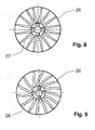
Fig. 8 und 9 zeigen schematisch jeweils eine bevorzugte Ausführungsform eines Verteilerelements, das in das erfindungsgemäße Stützelement integriert ist, in Draufsicht. -
Fig. 1 zeigt eine erste bevorzugte Ausführungsform der erfindungsgemäßen Vorrichtung mit einem flexiblen Behältnis oder Beutel 1, der einen Hohlraum 2 umschließt. Der Hohlraum 2 ist ganz oder teilweise mit einem Wirkstoff 3 gefüllt, der in der Regel in körniger Konsistenz oder pulverförmig vorliegt. Die Außenhaut des Beutels 1 ist eine flexible Außenhülle 4, die je nach Ausdehnung ballonförmig oder schlauchförmig den Hohlraum 2 umgibt. Gestützt wird die Außenhülle 4 durch ein inneres (säulenartiges) Stützelement 5, das in der Nähe seines ersten axialen Endes und in der Nähe seines zweiten axialen Endes mit der flexiblen Außenhülle 4 verbunden ist. Das Stützelement 5 ragt mit seinem ersten Ende durch die Außenhülle 4 hindurch, so dass der überstehende Teil des Stützelements 5 als ein Einlass 6 für Lösungsmittel 7 in den Hohlraum 2 der Vorrichtung dient. Das Stützelement 5 ragt außerdem mit seinem zweiten Ende durch die flexible Außenhülle 4 hindurch, so dass dieser überstehende Teil des Stützelements 5 als Auslass 8 für die fertige Lösung 9 dient. - In der gezeigten Ausführungsform ist das Stützelement 5 im wesentlichen rohrförmig aufgebaut. Um die Verbindung zwischen dem ersten Ende des Stützelements 5 und dem zweiten Ende des Stützelements 5 innerhalb des Rohrkörpers zu unterbrechen und damit das Lösungsmittel 7 zwangsläufig in dem Hohlraum 2 zu verteilen, ist wenigstens ein Rohrverschluss 10 in dem rohrförmigen Stützelement 5 vorgesehen. Auf diese Art wird sichergestellt, dass sich das Lösungsmittel 7 auf vordefinierten Lösungsmittelpfaden 11 durch den Wirkstoff 3 ausbreiten muss bis in die Nähe des Auslasses 8, wo die Lösung 9 aufgefangen wird und über den Auslass 8 nach außen transportiert wird. Der Rohrverschluss 10 ist vorzugsweise ein heißverprägter Rohrverschluss, der die statische Festigkeit des Stützelements (Rohres) 5 unverändert lässt. Alternativ kann ein Verschluss-Stopfen eingepresst werden.
- Einlass 6 und Auslass 8 sind auf beiden axialen Seiten des Behälters 1 gleich und daher beliebig einbaubar. Für das Einleiten der Flüssigkeit über den Einlass in das Behälter-innere Medium sowie für das Ausleiten der Lösung zum Auslass sind Verteiler- bzw. Sammelöffnungen im Stützelement 5 vorgesehen, wobei die Sammelöffnungen für die fertige Lösung 9 kurz oberhalb (stromauf) des eigentlichen Auslasses 8 schlitzförmig im Stützelement 5 angelegt sein können und z.B. durch Laser-Schneidprozesse oder Feinstanzen erzeugt werden.
- Das Befüllen des erfindungsgemäßen Beutels 1 mit pulverförmigen Stoffen erfolgt vorzugsweise durch eine Öffnung oben (im Bereich des Einlasses 6) im Beutel. Zum Befüllen wird das innere Stützelement 5 beiseite gedrückt, und der Wirkstoff wird trocken eingefüllt. Anschließend wird der Beutel 1 dicht an der Einfüllöffnung 23 verschweißt. Alternativ kann die Öffnung oben seitlich vom Einlass 6 angeordnet sein und verschweißt werden oder einen separaten Verschluss aufweisen.
- Ein solches, in
Fig. 1 gezeigtes beutelförmiges Behältnis 1 für pulverförmige Wirkstoffe (z.B. Bicarbonat) mit zentralem Stütz- und Anschlussrohr ist besonders geeignet für die Verwendung in Dialysemaschinen, bei denen das Behältnis 1 zwischen zwei (nicht gezeigten) festgelegten Zu- und Ablaufanschlüssen eingespannt wird. Der flexible Beutel 1 mit dem axialstabilen Stützelement 5 als Zentralelement vereinigt alle erforderlichen Funktionen in sich: - Anschlussmöglichkeit an Dialysemaschinen führender Hersteller,
- Zu- und Ablauffunktion von Lösungsmittel 7 bzw. fertiger Lösung 9,
- Verhindern einer direkten Verbindung von Zu- und Ablauf, so dass eine homogene Durchmischung gewährleistet ist,
- Siebfunktion gegen das Austreten von Pulver durch entsprechende, weiter unten erläuterte Maßnahmen,
- Verbindungsbereiche des Stützelements 5 zum vereinfachten Verschweißen mit dem Beutel 1,
- Sicherheit gegen Implosion bei Unterdruck.
-
Fig. 2 zeigt eine weitere Ausführungsform des Beutels 1 mit der flexiblen Außenhülle 4, in der sich der pulverförmige Wirkstoff 3 befindet. Über ein oberes, am Stützelement angeordnetes Träger- und Verteilerelement als Einlass 6 gelangt der Flüssigkeitszustrom des Lösungsmittels 7 in vorbestimmter Verteilungs- oder Versprühweise zu dem Wirkstoff 3. Das Stützelement 5 setzt sich in dieser Ausführungsform aus einem Rohr 12 und zwei Endstücken zusammen, die über jeweils einen Rohrbefestigungsdübel 13 mit dem Rohr 12 verbunden sind. Mit anderen Worten, die Zu- und Ablaufanschlüsse 6 und 8 sind auf das (Träger- und Distanzhalte-) Rohr 12 aufgesteckt. - Die Anschlussstücke 6 bzw. 8, insbesondere der Zulaufbereich des Einlasses 6, sind direkt hinter (stromab) den Verteiler-/Sammelöffnungen in dem Stützelement 5 mit einer scheibenförmigen Verteilerplatte 14 (Strömungsleitelement) ausgestattet, die ein direktes Herunterlaufen der zugeführten Flüssigkeit am Trägerrohr verhindert und so einer kernförmigen Ausspülung des pulverförmigen Wirkstoffes um die Mittelachse vorbeugt. Gleichzeitig wird eine gute Vermischung von Flüssigkeit und Feststoffen gefördert. Dies ist durch die Lösungsmittelpfade 11 in
Fig. 2 angedeutet. - Die Anschlussstücke 6 bzw. 8 können darüber hinaus insbesondere mit Gitterstäben oder einer siebartigen Oberfläche versehen sein, so dass körnige Wirkstoffe zurückgehalten werden. Dieses Siebelement 15 befindet sich vorzugsweise unmittelbar vor /stromauf zu) dem Auslass 8.
- Die Außenhülle 4 des Beutels 1 ist mit dem Trägerelement 5 und den Anschluss-Stücken 6 bzw. 8 fluiddicht verschweißt. Weitere Ausführungsformen sehen am Rohr 12 durch Spritzgießen oder Schweißen angeformte flanschartige Teller vor, auf die die gelochte Außenhülle 4 aufgeschweißt/aufgeklebt werden kann. Weiterhin kann die Verbindung zwischen Stützelement 5 und Beutel 1 durch schiffchenförmige Ansätze am Rohr 12 erfolgen, die mit der Außenhülle 4 verschweißt werden.
- Die Außenhülle 4 des Beutels 1 in der Ausführungsform nach
Fig. 1 und2 ist einstückig schlauchförmig dargestellt. Anstelle einer schlauchförmigen Außenhülle 4 kann aber auch eine aus zwei Folien zusammengesetzte Außenhülle 4 für den Beutel 1 verwendet werden. Eine derartige Außenhülle ist inFig. 3 gezeigt. Die Außenhülle 4 setzt sich aus einer ersten Folie 16 und einer zweiten Folie 17 zusammen. In der dargestellten Ausführungsform nimmt die erste Folie 16 in maximal ausgedehntem Zustand eine Trogform an. Durch den Trog verläuft das Stützelement 5, das an den zwei Stirnseiten des Trogs mit seinem ersten Ende 19 und seinem zweiten Ende 20 durch die erste Folie 16 nach außen tritt. Die erste Folie 16 bildet zusammen mit der zweiten Folie 17 einen abgeschlossenen Hohlraum 2. Die erste Folie 16 und die zweite Folie 17 werden über eine Schweißnaht 18 miteinander verbunden. - Die in
Fig. 3 gezeigte Ausführungsform mit der trogförmigen ersten Folie 16 bietet den Vorteil einer großen Einfüllöffnung 23 für den aufzulösenden Wirkstoff im Beutel 1. - In
Fig. 4 ist eine Ausführungsform des erfindungsgemäßen Stützelements 5 in perspektivischer Darstellung gezeigt. In dieser Ausführungsform setzt sich das Stützelement 5 aus einem Rohr 12 und einem ersten Durchführungsflansch 21 sowie einem zweiten Durchführungsflansch 22 zusammen. Die beiden Durchführungsflansche 21, 22 sind im wesentlichen gleichartig. Sie verfügen über den erforderlichen rohrförmigen Anschluss an eine Dialysemaschine, der als Einlass oder Auslass wie inFig. 1 gezeigt dient. Unterhalb bzw. oberhalb des Anschlusses sind ein oder mehrere siebförmige Ein- bzw. Auslässe (Verteiler-/Sammelöffnungen) vorgesehen. Die Durchführungsflansche 21, 22 können rund oder schiffchenförmig sein und stellen den Verbindungsbereich mit dem Beutel dar. An dem der Anschlussöffnung gegenüberliegenden Ende sind sie jeweils mit einem Rohrbefestigungsdübel (Blindstopfen) 13 versehen. Der Rohrbefestigungsdübel 13 wird eine Rohraufnahme in dem Rohr 12 (Rohrinnenraum) axial eingedrückt (eingepresst) und so mit dem Rohr 12 zu dem erfindungsgemäßen Stützelement 5 verbunden. Der Rohrbefestigungsdübel 13 ist vorzugsweise nicht durchgängig, so dass gleichzeitig ein Rohrverschluss 10 gebildet wird, der verhindert, dass Flüssigkeit durch das Rohr 12 fließt. - Durch Aufstecken der Durchführungsflansche 21, 22 auf das jeweilige Ende des z.B. extrudierten Rohres 12 wird so das tragende Stützelement 5 des Beutels 1 gebildet. Das Stützrohr 12 wird dann durch Schweißen mit dem Beutel 1 verbunden.
- Die Durchführungsflansche 21, 22 sind insbesondere beide vorzugsweise mit einer Flüssigkeitsverteilerplatte 14 ausgestattet, wie sie auch in
Fig. 2 gezeigt ist. - Die Befüllung des Beutels 1 kann über eine offene Seiten- oder auch Teil-Naht erfolgen, die nach dem Befüllvorgang verschlossen wird. Dies wird im folgenden anhand von
Fig. 5 erläutert. InFig. 5 ist ein Beutel 1 mit einer Außenhülle 4 aus zwei Folien 16 und 17 gezeigt. Die Folien 16, 17 sind an ihrer unteren Seite über eine Schweißnaht 18 miteinander verbunden. Die gegenüberliegende obere Schweißnaht ist noch nicht geschlossen, so dass sich eine Einfüllöffnung 23 für den einzufüllenden Wirkstoff 3 ergibt. Diese Einfüllöffnung 23 kann in Abhängigkeit von der Länge der Schweißnaht 18 so breit gewählt werden, dass das Einfüllen leicht durchführbar ist und andererseits bereits beim Einfüllen eine ausreichende Stabilität des Beutels 1 gewährleistet ist. - An ihrer Seite sind die beiden Folien 16, 17 über ein Seitenteil 24 miteinander verbunden. Das Seitenteil 24 ist eine balgförmige Folie zwischen den Folien 16, 17. Mit dem Seitenteil 24 ist das Stützelement 5 verbunden, und das Stützelement 5 durchstößt mit seinen Endabschnitten 19 und 20 jeweils einen Seitenteil 24, wobei der Übergang zwischen Stützelement 5 und Seitenteil 24 durch den jeweiligen Flansch 21, 22 abgedichtet wird.
- Die Durchführung des Stützelements 5 durch eine Folie ist nicht auf im wesentlichen ebene oder balgförmige Folien beschränkt. Eine alternative Ausführungsform zeigt
Fig. 6 . Aufgrund eines stabilen Durchführungsflansches 25 kann das Stützelement 5 auch durch eine stärker gekrümmte Außenhülle 4 hindurch geführt werden. - Der Aufbau des Durchführungsflansches 25 ist nochmals in
Fig. 7 dargestellt. Der Flansch 25 dient mit seinem integrierten Flüssigkeitskanal als Einlass 6 bzw. Auslass 8. Über einen Dübel 13 ist der Durchführungsflansch 25 mit dem Rohr 12 des erfindungsgemäßen Stützelements 5 verbunden, wobei keine Flüssigkeit von dem Flansch 25 in das Rohr 12 gelangt. Stattdessen ist unterhalb des Flansches ein Siebelement 15 angeordnet, durch das die zugeführte Flüssigkeit in den Beutel 1 strömt und damit den darin enthaltenen Wirkstoff benetzt. Das Siebelement 15 kann insbesondere in Zusammenhang mit der oben bereits beschriebenen Flüssigkeitsverteilerplatte 14 als Zulaufverteiler des Lösungsmittels dienen. - Ein solches Verteilerelement 26 mit Siebfunktion ist in
Fig. 8 und 9 in Draufsicht gezeigt. Dabei wird davon ausgegangen, dass unterhalb des Flüssigkeitszulaufes wie inFig. 2 und4 gezeigt eine Verteilerplatte 14 angeformt ist. Diese Verteilerplatte dient der Verteilung des Zustromes auf eine größere Pulveroberfläche und verhindert gleichzeitig das vorzeitige Ausspülen des pulverförmigen Wirkstoffes entlang der Mittelachse, welches zu einer verminderten Konzentration der zu bildenden Lösung führen kann. Ein Verteilerelement 26 ist zur Strömungslenkung mit Verteilerkanälen 27 oder Leitschaufeln 28 in gerader oder auch gekrümmter Form ausgestattet. Damit lässt sich dann eine optimale Benetzung des im Beutel 1 vorhandenen Wirkstoffes erreichen. - Die erfindungsgemäße Vorrichtung ist nicht auf die dargestellten Ausführungsformen beschränkt. Insbesondere kann bei dem Folienbehälter für pulverförmige Wirkstoffe für den geschweißten Beutel eine Mehrschicht- oder auch Monofolie als Material eingesetzt werden. Es eignet sich z.B. eine Folie aus den Schichten PE/PA/PE, die mit einer Gesamtstärke von 200 Micron koextrudiert ist, oder eine Folie aus den Schichten PP/PA/PE, die mit einer Gesamtstärke von 150 Micron koextrudiert ist, oder eine Monofolie aus PP mit einer Schichtstärke von bis zu 900 Micron. Die verwendeten Folien-Wandstärken können zwischen 150 Mircon und 900 Micron liegen. Alle genannten Folien sind auch mit entsprechenden Wandstärken für den Einsatz als Tiefziehfolie verwendbar. Diese Folien zeichnen sich durch hohe Reißfestigkeiten aus, was wiederum für eine Unterdruckfestigkeit und Unterdruckdichtigkeit des daraus hergestellten Beutels 1 bei den Betriebsarten des Unterdruckleersaugens des Behältnisses sehr vorteilhaft ist, da die Gefahr des Implodierens, wie sie bei starren Kartuschenkörpern gegeben ist, stark verringert werden kann. Innendruckbelastungen des Beutels von bis zu 3 bar sind mit den vorgenannten Materialien durchaus realisierbar.
- Außerdem können auf die Zu- und Ablauf-Anschlussstutzen nach dem Befüllen des Behältnisses 1 mit Wirkstoff 3 zwecks hygienischer Versiegelung und gg. auch als Originalitätsverschluss jeweils eine Abreißfolie mit Handhabungslasche aufgeschweißt werden, welche vor der Benutzung durch Abziehen entfernt werden. Ebenso sind aufgesteckte und mit den Behälter-Anschlüssen verriegelte Abbrech- oder Abdrehkappen als Originalitätsverschluss denkbar.
- Die Erfindung betrifft zusammenfassend eine Vorrichtung zum Herstellen einer Lösung, die umfasst: Ein einen Hohlraum (2) bildendes Behältnis (1) zum Aufnehmen von wenigstens einem aufzulösenden Wirkstoff (3), wenigstens einen Einlass (6) in den Hohlraum (2)zum Zuführen von wenigstens einem Lösungsmittel (7) in den Hohlraum (2) und wenigstens einen Auslass (8) aus dem Hohlraum (2) zum Ableiten der flüssigen Lösung (9) aus dem wenigstens einen Wirkstoff (3) und dem wenigstens einen Lösungsmittel (7) aus dem Hohlraum (2). Zur Schaffung einer axial starren Kartusche, welche in den heute gebräuchlichen Dialysemaschinen mit Kartuschen-Anschlusssystemen verwendet werden kann und kostengünstig herzustellen ist, wird erfindungsgemäß vorgeschlagen, dass der Hohlraum (2) bzw. das Behältnis (1) aufweist: eine flexible Außenhülle (4) zum Umschließen des Hohlraums (2) und ein säulenartiges, inneres Stützelement (5) zum Aufspannen der flexiblen Außenhülle (4) zwischen wenigstens zwei Punkten, wobei das Stützelement (5) an seinem ersten Ende (19) den wenigstens einen Einlass (6) und an seinem zweiten Ende (20) den wenigstens einen Auslass (8) umfasst und von der flexiblen Außenhülle (4) umschlossen wird.
-
- 1
- Behälter, Beutel, Behältnis
- 2
- Hohlraum
- 3
- Wirkstoff
- 4
- flexible Außenhülle, Schlauchfolie
- 5
- Stützelement
- 6
- Einlass
- 7
- Lösungsmittel
- 8
- Auslass
- 9
- Lösung
- 10
- Rohrverschluss
- 11
- Lösungsmittelpfade
- 12
- Rohr
- 13
- Rohrbefestigungsdübel
- 14
- Flüssigkeitsverteilerplatte
- 15
- Siebelement
- 16
- erste Folie
- 17
- zweite Folie
- 18
- Schweißnaht
- 19
- erstes Ende von Stützelement
- 20
- zweites Ende von Stützelement
- 21
- erster Durchführungsflansch
- 22
- zweiter Durchführungsflansch
- 23
- Einfüllöffnung
- 24
- Seitenteil
- 25
- Durchführungsflansch
- 26
- Verteilerelement
- 27
- Verteilerkanäle
- 28
- Leitschaufeln
Claims (8)
- Vorrichtung zum Herstellen einer Lösung (9), die folgende Teile hat:Ein einen Hohlraum (2) ausbildendes Behältnis (1) zum Aufnehmen von wenigstens einem aufzulösenden Wirkstoff (3),wenigstens einen Einlass (6) in den Hohlraum (2) zum Zuführen von wenigstens einem Lösungsmittel (7) in den Hohlraum (2) undwenigstens einen Auslass (8) aus dem Hohlraum (2) zum Ableiten der flüssigen Lösung (9) aus dem wenigstens einen Wirkstoff (3) und dem wenigstens einen Lösungsmittel (7) aus dem Hohlraum (2),dadurch gekennzeichnet, dassdas Behältnis (1) aufweist:eine flexible Außenhülle (4) zum Umschließen des Hohlraums (2) undein inneres vorzugsweise säulenartiges Stützelement (5) zum Aufspannen der flexiblen Außenhülle (4) zwischen zumindest zwei Punkten,wobei das Stützelement (5) an seinem ersten Ende (19) den wenigstens einen Einlass (6) und an seinem zweiten Ende (20) den wenigstens einen Auslass (8) aufweist und von der flexiblen Außenhülle (4) umschlossen wird und wobei das Stützelement (5) einstückig mit dem wenigstens einen Einlass (6) und dem wenigstens einen Auslass (8) verbunden/ausgebildet ist.
- Vorrichtung nach Anspruch 1, bei der die flexible Außenhülle (4) eine Schlauchfolie ist, die an ihren beidseitigen Öffnungen mit dem Stützelement (5) dicht verschweißt ist.
- Vorrichtung nach Anspruch 1, bei der die flexible Außenhülle (4) aus einer ersten (16) und einer zweiten Folie (17) gebildet wird, die an ihrem jeweiligen Rand durch eine Schweißnaht (18) miteinander und mit dem Stützelement (5) verbunden sind, so dass dieses zu Anschlusszwecken oben und unten aus der Außenhülle (4) stutzenförmig herausragt.
- Vorrichtung nach einem der vorangehenden Ansprüche, bei der das Stützelement (5) und die Außenhülle (4) durch Durchführungsflansche (21, 22; 25) verbunden ist.
- Vorrichtung nach einem der vorangehenden Ansprüche, bei der das Stützelement (5) ein Rohr (12) hat/ist, das unterhalb von dem wenigstens einen Einlass (6) und oberhalb von dem wenigstens einen Auslass (8) einen fluiddichten Rohrverschluss oder Pfropfen (10) aufweist.
- Vorrichtung nach einem der Ansprüche 1 bis 4, bei der das Stützelement (5) ein Rohr (12) hat/ist, in das unterhalb von dem wenigstens einen Einlass (6) und oberhalb von dem wenigstens einen Auslass (8) ein Verschlussstopfen eingepresst ist.
- Vorrichtung nach einem der vorangehenden Ansprüche, bei der das Stützelement (5) jeweils wenigstens ein Siebelement (15) nach dem wenigstens einen Einlass (6) und/oder vor dem wenigstens einen Auslass (8) aufweist.
- Vorrichtung nach einem der vorangehenden Ansprüche, bei der das Stützelement (5) jeweils wenigstens ein Verteilerelement (26) mit mehreren Verteilerkanälen (27) und/oder mehreren Leitschaufeln (28) nach dem wenigstens einen Einlass (6) und/oder vor dem wenigstens einen Auslass (8) aufweist, um einströmendes Lösungsmittel (7) vorbestimmt in den Hohlraum (2) zu verteilen und/oder fertige Lösung (9) vorbestimmt in den Auslass (8) zu leiten.
Applications Claiming Priority (1)
| Application Number | Priority Date | Filing Date | Title |
|---|---|---|---|
| DE102013108082.0A DE102013108082A1 (de) | 2013-07-29 | 2013-07-29 | Vorrichtung zum Herstellen einer Lösung, inbesondere in/an einer Dialysemaschine |
Publications (2)
| Publication Number | Publication Date |
|---|---|
| EP2832339A1 true EP2832339A1 (de) | 2015-02-04 |
| EP2832339B1 EP2832339B1 (de) | 2017-02-01 |
Family
ID=51225380
Family Applications (1)
| Application Number | Title | Priority Date | Filing Date |
|---|---|---|---|
| EP14178790.3A Active EP2832339B1 (de) | 2013-07-29 | 2014-07-28 | Vorrichtung zum herstellen einer lösung, insbesondere in/an einer dialysemaschine |
Country Status (4)
| Country | Link |
|---|---|
| US (1) | US9993784B2 (de) |
| EP (1) | EP2832339B1 (de) |
| CN (2) | CN104338188B (de) |
| DE (1) | DE102013108082A1 (de) |
Cited By (2)
| Publication number | Priority date | Publication date | Assignee | Title |
|---|---|---|---|---|
| EP3085399A1 (de) * | 2015-04-24 | 2016-10-26 | D_MED Consulting AG | Dialysetrockenkonzentrat-Kartusche |
| EP3290068A1 (de) * | 2016-08-30 | 2018-03-07 | B. Braun Avitum AG | Siebartige filtereinrichtung für einen kartuschenförmigen behälter |
Families Citing this family (18)
| Publication number | Priority date | Publication date | Assignee | Title |
|---|---|---|---|---|
| DE102013108082A1 (de) * | 2013-07-29 | 2015-01-29 | B. Braun Avitum Ag | Vorrichtung zum Herstellen einer Lösung, inbesondere in/an einer Dialysemaschine |
| JP6912387B2 (ja) * | 2015-05-27 | 2021-08-04 | トリオメド エービーTriomed Ab | 吸着透析を実行するためのカートリッジ、方法、および、装置 |
| US9814819B2 (en) * | 2015-06-15 | 2017-11-14 | Fresenius Medical Care Holdings, Inc. | Dialysis machines with integral salt solution chambers and related methods |
| WO2017051773A1 (ja) * | 2015-09-25 | 2017-03-30 | 二プロ株式会社 | 透析用容器 |
| ES2908601T3 (es) | 2016-08-19 | 2022-05-03 | Outset Medical Inc | Sistema y métodos de diálisis peritoneal |
| EP3562528A1 (de) * | 2016-12-29 | 2019-11-06 | Fresenius Medical Care Holdings, Inc. | Flüssigkeitsbehälter für ein hämodialysesystem |
| CN106818695A (zh) * | 2017-02-27 | 2017-06-13 | 四川雷神空天科技有限公司 | 容纳装置 |
| US11452803B2 (en) | 2017-05-12 | 2022-09-27 | Medtronic, Inc. | Infusate containers |
| WO2018228608A2 (zh) * | 2017-06-12 | 2018-12-20 | 谢华南 | 密闭式透析粉容器 |
| CN107224623B (zh) * | 2017-06-12 | 2019-11-12 | 谢华南 | 密闭式透析粉容器 |
| EP3703774B1 (de) | 2017-11-01 | 2024-06-19 | Baxter International Inc | Mischung zum online-erzeugung von medizinische flüssigkeiten |
| US10456107B2 (en) * | 2018-02-20 | 2019-10-29 | General Electric Company | Ultrasound imaging device and method for transmitting audible sounds |
| US11419791B2 (en) | 2018-07-05 | 2022-08-23 | Fresenius Medical Care Holdings, Inc. | Flexible container systems and nozzles, and related methods |
| BR112021021836A2 (pt) * | 2019-04-30 | 2022-01-04 | Outset Medical Inc | Métodos para calcular a pressão arterial, para criar dialisato em um sistema de diálise, para medir a porcentagem de rejeição em um sistema de diálise, para coletar e analisar plasma sanguíneo, para remover gás de um circuito extracorpóreo de um sistema de diálise, para inferir uma pressão de linha em um circuito extracorpóreo de um sistema de diálise, para prover terapia de diálise extracorpórea e intracorpórea, para montar um conjunto de tubos de paciente no estilo cartucho em uma máquina de diálise e para preparar uma máquina de diálise para terapia de diálise, câmaras de fluxo e de remoção de ar, sistema de diálise, subsistema de dispensação de dialisato, filtro de micróbio/endotoxina de uso único, dialisador, dispositivo para medir pressão de um sistema de diálise, e, conjunto de tubos de sangue |
| CN110627921A (zh) * | 2019-10-24 | 2019-12-31 | 海雅美生物技术(珠海)有限公司 | 一种交联透明质酸透析装置 |
| WO2021087870A1 (en) * | 2019-11-07 | 2021-05-14 | Fresenius Medical Care Deutschland Gmbh | Container, cartridge, corresponding combination, corresponding receiving base, corresponding medical device and corresponding methods |
| CN112915289A (zh) * | 2021-03-31 | 2021-06-08 | 广州骐骥生物科技有限公司 | 血液透析用干粉筒及其制备方法 |
| DE102023115358A1 (de) * | 2023-06-13 | 2024-12-19 | B.Braun Avitum Ag | Bikarbonat-Kartusche |
Citations (6)
| Publication number | Priority date | Publication date | Assignee | Title |
|---|---|---|---|---|
| DE19801107A1 (de) * | 1998-01-15 | 1999-07-22 | Haas Medizintechnik Gmbh | Kartusche zur On-Line-Aufbereitung einer Flüssigkeit |
| DE19852982C1 (de) | 1998-11-17 | 2000-03-16 | Braun Melsungen Ag | Kartuschenhalter für eine Dialysemaschine |
| DE10100549A1 (de) * | 2001-01-08 | 2002-07-18 | Franz Peter Ritter | Salzbehältersystem für Dialysegeräte |
| WO2007144427A2 (en) * | 2006-06-15 | 2007-12-21 | As Ldiamon | Container, system and method for providing a solution |
| WO2011161064A1 (en) * | 2010-06-23 | 2011-12-29 | Gambro Lundia Ab | Preparation of medical solutions from powdery material |
| DE102011017048A1 (de) * | 2011-04-14 | 2012-10-18 | Fresenius Medical Care Deutschland Gmbh | Mehrkammercontainer zur Herstellung medizinischer Lösungen |
Family Cites Families (6)
| Publication number | Priority date | Publication date | Assignee | Title |
|---|---|---|---|---|
| DE4422100C1 (de) * | 1994-06-24 | 1995-12-14 | Fresenius Ag | Flexible medizinische Verpackungseinheit für die Hämodialyse zur Herstellung eines Dialysierflüssigkeit-Konzentrats sowie Vorrichtung hierfür |
| FR2766797B1 (fr) * | 1997-07-30 | 1999-09-17 | Smad | Conditionnement pour au moins une matiere solide, notamment sous forme granuleuse ou pulverulente |
| DE602004022075D1 (de) * | 2003-10-21 | 2009-08-27 | Novo Nordisk As | Reservoirvorrichtung mit integriertem befestigungsmittel |
| EP2537541A1 (de) | 2011-06-23 | 2012-12-26 | Metpro AB | Behälter und Anschluss zur Bereitstellung einer medizinischen Lösung |
| JP2013081538A (ja) | 2011-10-06 | 2013-05-09 | Jms Co Ltd | 2液混合型輸液バッグ |
| DE102013108082A1 (de) | 2013-07-29 | 2015-01-29 | B. Braun Avitum Ag | Vorrichtung zum Herstellen einer Lösung, inbesondere in/an einer Dialysemaschine |
-
2013
- 2013-07-29 DE DE102013108082.0A patent/DE102013108082A1/de not_active Withdrawn
-
2014
- 2014-07-28 EP EP14178790.3A patent/EP2832339B1/de active Active
- 2014-07-28 US US14/444,494 patent/US9993784B2/en active Active
- 2014-07-29 CN CN201410367102.7A patent/CN104338188B/zh active Active
- 2014-07-29 CN CN201420422993.7U patent/CN204446743U/zh not_active Expired - Lifetime
Patent Citations (6)
| Publication number | Priority date | Publication date | Assignee | Title |
|---|---|---|---|---|
| DE19801107A1 (de) * | 1998-01-15 | 1999-07-22 | Haas Medizintechnik Gmbh | Kartusche zur On-Line-Aufbereitung einer Flüssigkeit |
| DE19852982C1 (de) | 1998-11-17 | 2000-03-16 | Braun Melsungen Ag | Kartuschenhalter für eine Dialysemaschine |
| DE10100549A1 (de) * | 2001-01-08 | 2002-07-18 | Franz Peter Ritter | Salzbehältersystem für Dialysegeräte |
| WO2007144427A2 (en) * | 2006-06-15 | 2007-12-21 | As Ldiamon | Container, system and method for providing a solution |
| WO2011161064A1 (en) * | 2010-06-23 | 2011-12-29 | Gambro Lundia Ab | Preparation of medical solutions from powdery material |
| DE102011017048A1 (de) * | 2011-04-14 | 2012-10-18 | Fresenius Medical Care Deutschland Gmbh | Mehrkammercontainer zur Herstellung medizinischer Lösungen |
Cited By (3)
| Publication number | Priority date | Publication date | Assignee | Title |
|---|---|---|---|---|
| EP3085399A1 (de) * | 2015-04-24 | 2016-10-26 | D_MED Consulting AG | Dialysetrockenkonzentrat-Kartusche |
| EP3290068A1 (de) * | 2016-08-30 | 2018-03-07 | B. Braun Avitum AG | Siebartige filtereinrichtung für einen kartuschenförmigen behälter |
| US10569235B2 (en) | 2016-08-30 | 2020-02-25 | B. Braun Avitum Ag | Sieve-like filter unit for cartridge-shaped receptacle |
Also Published As
| Publication number | Publication date |
|---|---|
| US20150029817A1 (en) | 2015-01-29 |
| DE102013108082A1 (de) | 2015-01-29 |
| CN104338188B (zh) | 2018-10-12 |
| CN104338188A (zh) | 2015-02-11 |
| CN204446743U (zh) | 2015-07-08 |
| US9993784B2 (en) | 2018-06-12 |
| EP2832339B1 (de) | 2017-02-01 |
Similar Documents
| Publication | Publication Date | Title |
|---|---|---|
| EP2832339B1 (de) | Vorrichtung zum herstellen einer lösung, insbesondere in/an einer dialysemaschine | |
| DE69812600T2 (de) | Stopfen und formveränderlicher behälter mit einem solchen stopfen | |
| DE2612518C3 (de) | Doppelkammerbehälter zur Aufnahme von Blut o.dgl | |
| EP0574410B1 (de) | Blutbeutelanordnung | |
| EP1140259B1 (de) | Mehrkammer-ampulle zum ausgeben eines aus mehreren substanzen bestehenden gemisches | |
| EP0700280B1 (de) | Peelfähige polymere mehrschichtfolie für einen medizinischen mehrkammerbeutel und verfahren zu dessen herstellung | |
| DE4107223C1 (de) | ||
| EP2025355B1 (de) | Behältnis zur Verwendung in der Dialyse | |
| EP2419257A1 (de) | Vorrichtung zum verschweissen von thermoplastischen schläuchen | |
| EP0535688A1 (de) | Spornbestücktes Verpackungssystem | |
| EP2332610A1 (de) | Anschlusssystem für Nahrungsbehälter zur enteralen Ernährung | |
| DE4432993C1 (de) | Mischeinrichtung für mittels einer Spritze zu verabreichende Mittel | |
| EP2384822A1 (de) | Kartuschenverschluss und Kartusche mit einem solchen Verschluss | |
| DE3627231C2 (de) | Überleitungsgerät zum Mischen von in unterschiedlichen Behältern befindlichen Medikamenten | |
| DE60119136T2 (de) | Beutel zum verpacken einer substanz mit integrierter kanüle und band aus solchen beuteln | |
| EP3549572A1 (de) | Behältnis und set zur bereitstellung parenteraler nahrung | |
| WO2013034575A1 (de) | Einfüllstutzen für einen flüssigkeitsvorratsbehälter eines kraftfahrzeugs mit einem integrierten entlüftungskanal | |
| DE20200689U1 (de) | Einschweiß-Schiffchen für einen Beutel | |
| DE10041295A1 (de) | Verfahren zur Herstellung einer Zweikammer-Anordnung und Zweikammer-Anordnung | |
| EP3297701A1 (de) | Dialysekonzentratbehälter | |
| DE102008053131A1 (de) | Verfahren und Anordnung zum Sterilisieren, insbesondere zum Sterilisieren eines Adsorbers | |
| DE2422433A1 (de) | Mit einem bypasskanal versehene anzapfvorrichtung | |
| WO2005006983A1 (de) | Fluidsystem mit sicherungseinrichtung | |
| EP3200849B1 (de) | Vorrichtung mit einem beutelförmigen behältnis sowie verfahren zum gasblasenfreien befüllen eines pumpenbetriebenen, hohlleitungsgestützten flüssigkeitskreislaufes mittels der vorrichtung | |
| EP3661631A1 (de) | Filtrationsvorrichtung mit integriertem flussminderer und verfahren zur vollständigen benetzung einer filtermembran |
Legal Events
| Date | Code | Title | Description |
|---|---|---|---|
| 17P | Request for examination filed |
Effective date: 20140728 |
|
| AK | Designated contracting states |
Kind code of ref document: A1 Designated state(s): AL AT BE BG CH CY CZ DE DK EE ES FI FR GB GR HR HU IE IS IT LI LT LU LV MC MK MT NL NO PL PT RO RS SE SI SK SM TR |
|
| AX | Request for extension of the european patent |
Extension state: BA ME |
|
| PUAI | Public reference made under article 153(3) epc to a published international application that has entered the european phase |
Free format text: ORIGINAL CODE: 0009012 |
|
| R17P | Request for examination filed (corrected) |
Effective date: 20150611 |
|
| RBV | Designated contracting states (corrected) |
Designated state(s): AL AT BE BG CH CY CZ DE DK EE ES FI FR GB GR HR HU IE IS IT LI LT LU LV MC MK MT NL NO PL PT RO RS SE SI SK SM TR |
|
| 17Q | First examination report despatched |
Effective date: 20150831 |
|
| GRAP | Despatch of communication of intention to grant a patent |
Free format text: ORIGINAL CODE: EPIDOSNIGR1 |
|
| INTG | Intention to grant announced |
Effective date: 20160809 |
|
| GRAS | Grant fee paid |
Free format text: ORIGINAL CODE: EPIDOSNIGR3 |
|
| GRAA | (expected) grant |
Free format text: ORIGINAL CODE: 0009210 |
|
| AK | Designated contracting states |
Kind code of ref document: B1 Designated state(s): AL AT BE BG CH CY CZ DE DK EE ES FI FR GB GR HR HU IE IS IT LI LT LU LV MC MK MT NL NO PL PT RO RS SE SI SK SM TR |
|
| REG | Reference to a national code |
Ref country code: GB Ref legal event code: FG4D Free format text: NOT ENGLISH |
|
| REG | Reference to a national code |
Ref country code: CH Ref legal event code: EP Ref country code: AT Ref legal event code: REF Ref document number: 864948 Country of ref document: AT Kind code of ref document: T Effective date: 20170215 |
|
| REG | Reference to a national code |
Ref country code: IE Ref legal event code: FG4D Free format text: LANGUAGE OF EP DOCUMENT: GERMAN |
|
| REG | Reference to a national code |
Ref country code: DE Ref legal event code: R096 Ref document number: 502014002591 Country of ref document: DE |
|
| REG | Reference to a national code |
Ref country code: NL Ref legal event code: MP Effective date: 20170201 |
|
| REG | Reference to a national code |
Ref country code: LT Ref legal event code: MG4D |
|
| REG | Reference to a national code |
Ref country code: FR Ref legal event code: PLFP Year of fee payment: 4 |
|
| PG25 | Lapsed in a contracting state [announced via postgrant information from national office to epo] |
Ref country code: HR Free format text: LAPSE BECAUSE OF FAILURE TO SUBMIT A TRANSLATION OF THE DESCRIPTION OR TO PAY THE FEE WITHIN THE PRESCRIBED TIME-LIMIT Effective date: 20170201 Ref country code: IS Free format text: LAPSE BECAUSE OF FAILURE TO SUBMIT A TRANSLATION OF THE DESCRIPTION OR TO PAY THE FEE WITHIN THE PRESCRIBED TIME-LIMIT Effective date: 20170601 Ref country code: NO Free format text: LAPSE BECAUSE OF FAILURE TO SUBMIT A TRANSLATION OF THE DESCRIPTION OR TO PAY THE FEE WITHIN THE PRESCRIBED TIME-LIMIT Effective date: 20170501 Ref country code: FI Free format text: LAPSE BECAUSE OF FAILURE TO SUBMIT A TRANSLATION OF THE DESCRIPTION OR TO PAY THE FEE WITHIN THE PRESCRIBED TIME-LIMIT Effective date: 20170201 Ref country code: LT Free format text: LAPSE BECAUSE OF FAILURE TO SUBMIT A TRANSLATION OF THE DESCRIPTION OR TO PAY THE FEE WITHIN THE PRESCRIBED TIME-LIMIT Effective date: 20170201 Ref country code: GR Free format text: LAPSE BECAUSE OF FAILURE TO SUBMIT A TRANSLATION OF THE DESCRIPTION OR TO PAY THE FEE WITHIN THE PRESCRIBED TIME-LIMIT Effective date: 20170502 |
|
| PG25 | Lapsed in a contracting state [announced via postgrant information from national office to epo] |
Ref country code: BG Free format text: LAPSE BECAUSE OF FAILURE TO SUBMIT A TRANSLATION OF THE DESCRIPTION OR TO PAY THE FEE WITHIN THE PRESCRIBED TIME-LIMIT Effective date: 20170501 Ref country code: RS Free format text: LAPSE BECAUSE OF FAILURE TO SUBMIT A TRANSLATION OF THE DESCRIPTION OR TO PAY THE FEE WITHIN THE PRESCRIBED TIME-LIMIT Effective date: 20170201 Ref country code: ES Free format text: LAPSE BECAUSE OF FAILURE TO SUBMIT A TRANSLATION OF THE DESCRIPTION OR TO PAY THE FEE WITHIN THE PRESCRIBED TIME-LIMIT Effective date: 20170201 Ref country code: PT Free format text: LAPSE BECAUSE OF FAILURE TO SUBMIT A TRANSLATION OF THE DESCRIPTION OR TO PAY THE FEE WITHIN THE PRESCRIBED TIME-LIMIT Effective date: 20170601 Ref country code: LV Free format text: LAPSE BECAUSE OF FAILURE TO SUBMIT A TRANSLATION OF THE DESCRIPTION OR TO PAY THE FEE WITHIN THE PRESCRIBED TIME-LIMIT Effective date: 20170201 Ref country code: PL Free format text: LAPSE BECAUSE OF FAILURE TO SUBMIT A TRANSLATION OF THE DESCRIPTION OR TO PAY THE FEE WITHIN THE PRESCRIBED TIME-LIMIT Effective date: 20170201 Ref country code: NL Free format text: LAPSE BECAUSE OF FAILURE TO SUBMIT A TRANSLATION OF THE DESCRIPTION OR TO PAY THE FEE WITHIN THE PRESCRIBED TIME-LIMIT Effective date: 20170201 Ref country code: SE Free format text: LAPSE BECAUSE OF FAILURE TO SUBMIT A TRANSLATION OF THE DESCRIPTION OR TO PAY THE FEE WITHIN THE PRESCRIBED TIME-LIMIT Effective date: 20170201 |
|
| PG25 | Lapsed in a contracting state [announced via postgrant information from national office to epo] |
Ref country code: EE Free format text: LAPSE BECAUSE OF FAILURE TO SUBMIT A TRANSLATION OF THE DESCRIPTION OR TO PAY THE FEE WITHIN THE PRESCRIBED TIME-LIMIT Effective date: 20170201 Ref country code: CZ Free format text: LAPSE BECAUSE OF FAILURE TO SUBMIT A TRANSLATION OF THE DESCRIPTION OR TO PAY THE FEE WITHIN THE PRESCRIBED TIME-LIMIT Effective date: 20170201 Ref country code: RO Free format text: LAPSE BECAUSE OF FAILURE TO SUBMIT A TRANSLATION OF THE DESCRIPTION OR TO PAY THE FEE WITHIN THE PRESCRIBED TIME-LIMIT Effective date: 20170201 Ref country code: SK Free format text: LAPSE BECAUSE OF FAILURE TO SUBMIT A TRANSLATION OF THE DESCRIPTION OR TO PAY THE FEE WITHIN THE PRESCRIBED TIME-LIMIT Effective date: 20170201 |
|
| REG | Reference to a national code |
Ref country code: DE Ref legal event code: R097 Ref document number: 502014002591 Country of ref document: DE |
|
| PG25 | Lapsed in a contracting state [announced via postgrant information from national office to epo] |
Ref country code: SM Free format text: LAPSE BECAUSE OF FAILURE TO SUBMIT A TRANSLATION OF THE DESCRIPTION OR TO PAY THE FEE WITHIN THE PRESCRIBED TIME-LIMIT Effective date: 20170201 Ref country code: DK Free format text: LAPSE BECAUSE OF FAILURE TO SUBMIT A TRANSLATION OF THE DESCRIPTION OR TO PAY THE FEE WITHIN THE PRESCRIBED TIME-LIMIT Effective date: 20170201 |
|
| PLBE | No opposition filed within time limit |
Free format text: ORIGINAL CODE: 0009261 |
|
| STAA | Information on the status of an ep patent application or granted ep patent |
Free format text: STATUS: NO OPPOSITION FILED WITHIN TIME LIMIT |
|
| 26N | No opposition filed |
Effective date: 20171103 |
|
| PG25 | Lapsed in a contracting state [announced via postgrant information from national office to epo] |
Ref country code: SI Free format text: LAPSE BECAUSE OF FAILURE TO SUBMIT A TRANSLATION OF THE DESCRIPTION OR TO PAY THE FEE WITHIN THE PRESCRIBED TIME-LIMIT Effective date: 20170201 |
|
| REG | Reference to a national code |
Ref country code: CH Ref legal event code: PL |
|
| REG | Reference to a national code |
Ref country code: IE Ref legal event code: MM4A |
|
| PG25 | Lapsed in a contracting state [announced via postgrant information from national office to epo] |
Ref country code: LI Free format text: LAPSE BECAUSE OF NON-PAYMENT OF DUE FEES Effective date: 20170731 Ref country code: CH Free format text: LAPSE BECAUSE OF NON-PAYMENT OF DUE FEES Effective date: 20170731 Ref country code: IE Free format text: LAPSE BECAUSE OF NON-PAYMENT OF DUE FEES Effective date: 20170728 |
|
| REG | Reference to a national code |
Ref country code: BE Ref legal event code: MM Effective date: 20170731 |
|
| PG25 | Lapsed in a contracting state [announced via postgrant information from national office to epo] |
Ref country code: LU Free format text: LAPSE BECAUSE OF NON-PAYMENT OF DUE FEES Effective date: 20170728 |
|
| REG | Reference to a national code |
Ref country code: FR Ref legal event code: PLFP Year of fee payment: 5 |
|
| PG25 | Lapsed in a contracting state [announced via postgrant information from national office to epo] |
Ref country code: BE Free format text: LAPSE BECAUSE OF NON-PAYMENT OF DUE FEES Effective date: 20170731 |
|
| PG25 | Lapsed in a contracting state [announced via postgrant information from national office to epo] |
Ref country code: MT Free format text: LAPSE BECAUSE OF FAILURE TO SUBMIT A TRANSLATION OF THE DESCRIPTION OR TO PAY THE FEE WITHIN THE PRESCRIBED TIME-LIMIT Effective date: 20170201 |
|
| GBPC | Gb: european patent ceased through non-payment of renewal fee |
Effective date: 20180728 |
|
| PG25 | Lapsed in a contracting state [announced via postgrant information from national office to epo] |
Ref country code: GB Free format text: LAPSE BECAUSE OF NON-PAYMENT OF DUE FEES Effective date: 20180728 |
|
| PG25 | Lapsed in a contracting state [announced via postgrant information from national office to epo] |
Ref country code: MC Free format text: LAPSE BECAUSE OF FAILURE TO SUBMIT A TRANSLATION OF THE DESCRIPTION OR TO PAY THE FEE WITHIN THE PRESCRIBED TIME-LIMIT Effective date: 20170201 Ref country code: HU Free format text: LAPSE BECAUSE OF FAILURE TO SUBMIT A TRANSLATION OF THE DESCRIPTION OR TO PAY THE FEE WITHIN THE PRESCRIBED TIME-LIMIT; INVALID AB INITIO Effective date: 20140728 |
|
| PG25 | Lapsed in a contracting state [announced via postgrant information from national office to epo] |
Ref country code: CY Free format text: LAPSE BECAUSE OF FAILURE TO SUBMIT A TRANSLATION OF THE DESCRIPTION OR TO PAY THE FEE WITHIN THE PRESCRIBED TIME-LIMIT Effective date: 20170201 |
|
| PG25 | Lapsed in a contracting state [announced via postgrant information from national office to epo] |
Ref country code: MK Free format text: LAPSE BECAUSE OF FAILURE TO SUBMIT A TRANSLATION OF THE DESCRIPTION OR TO PAY THE FEE WITHIN THE PRESCRIBED TIME-LIMIT Effective date: 20170201 |
|
| PG25 | Lapsed in a contracting state [announced via postgrant information from national office to epo] |
Ref country code: TR Free format text: LAPSE BECAUSE OF FAILURE TO SUBMIT A TRANSLATION OF THE DESCRIPTION OR TO PAY THE FEE WITHIN THE PRESCRIBED TIME-LIMIT Effective date: 20170201 |
|
| PG25 | Lapsed in a contracting state [announced via postgrant information from national office to epo] |
Ref country code: AL Free format text: LAPSE BECAUSE OF FAILURE TO SUBMIT A TRANSLATION OF THE DESCRIPTION OR TO PAY THE FEE WITHIN THE PRESCRIBED TIME-LIMIT Effective date: 20170201 |
|
| REG | Reference to a national code |
Ref country code: AT Ref legal event code: MM01 Ref document number: 864948 Country of ref document: AT Kind code of ref document: T Effective date: 20190728 |
|
| PG25 | Lapsed in a contracting state [announced via postgrant information from national office to epo] |
Ref country code: AT Free format text: LAPSE BECAUSE OF NON-PAYMENT OF DUE FEES Effective date: 20190728 |
|
| P01 | Opt-out of the competence of the unified patent court (upc) registered |
Free format text: CASE NUMBER: APP_5268/2025 Effective date: 20250131 |
|
| PGFP | Annual fee paid to national office [announced via postgrant information from national office to epo] |
Ref country code: DE Payment date: 20250722 Year of fee payment: 12 |
|
| PGFP | Annual fee paid to national office [announced via postgrant information from national office to epo] |
Ref country code: IT Payment date: 20250731 Year of fee payment: 12 |
|
| PGFP | Annual fee paid to national office [announced via postgrant information from national office to epo] |
Ref country code: FR Payment date: 20250723 Year of fee payment: 12 |