EP2829808A1 - Hotte aspirante - Google Patents
Hotte aspirante Download PDFInfo
- Publication number
- EP2829808A1 EP2829808A1 EP13003685.8A EP13003685A EP2829808A1 EP 2829808 A1 EP2829808 A1 EP 2829808A1 EP 13003685 A EP13003685 A EP 13003685A EP 2829808 A1 EP2829808 A1 EP 2829808A1
- Authority
- EP
- European Patent Office
- Prior art keywords
- hood
- extractor hood
- air
- air duct
- filter
- Prior art date
- Legal status (The legal status is an assumption and is not a legal conclusion. Google has not performed a legal analysis and makes no representation as to the accuracy of the status listed.)
- Granted
Links
- 239000000284 extract Substances 0.000 claims abstract description 27
- 239000004519 grease Substances 0.000 claims description 33
- 238000004140 cleaning Methods 0.000 claims description 6
- 238000003780 insertion Methods 0.000 claims description 5
- 230000037431 insertion Effects 0.000 claims description 5
- 239000000463 material Substances 0.000 claims description 3
- 238000010411 cooking Methods 0.000 description 6
- OKTJSMMVPCPJKN-UHFFFAOYSA-N Carbon Chemical compound [C] OKTJSMMVPCPJKN-UHFFFAOYSA-N 0.000 description 4
- 239000003517 fume Substances 0.000 description 4
- 239000002184 metal Substances 0.000 description 3
- 230000000630 rising effect Effects 0.000 description 3
- 230000002093 peripheral effect Effects 0.000 description 2
- 238000000926 separation method Methods 0.000 description 2
- 229910001220 stainless steel Inorganic materials 0.000 description 2
- 239000010935 stainless steel Substances 0.000 description 2
- 238000010276 construction Methods 0.000 description 1
- 230000001419 dependent effect Effects 0.000 description 1
- 230000008021 deposition Effects 0.000 description 1
- 238000002845 discoloration Methods 0.000 description 1
- 230000000694 effects Effects 0.000 description 1
- 239000007789 gas Substances 0.000 description 1
- 238000009434 installation Methods 0.000 description 1
- 230000003134 recirculating effect Effects 0.000 description 1
- 239000002356 single layer Substances 0.000 description 1
- 239000013589 supplement Substances 0.000 description 1
- 239000000725 suspension Substances 0.000 description 1
Images


Classifications
-
- F—MECHANICAL ENGINEERING; LIGHTING; HEATING; WEAPONS; BLASTING
- F24—HEATING; RANGES; VENTILATING
- F24C—DOMESTIC STOVES OR RANGES ; DETAILS OF DOMESTIC STOVES OR RANGES, OF GENERAL APPLICATION
- F24C15/00—Details
- F24C15/20—Removing cooking fumes
- F24C15/2078—Removing cooking fumes movable
- F24C15/2092—Removing cooking fumes movable extendable or pivotable
Definitions
- the present invention relates to an extractor hood with a grease filter and a suction system for applying this grease filter under negative pressure to promote gases to be purified, in particular by cooking fumes contaminated air through this grease filter, and with a suction in front of the grease filter, which by Heilleitvorlegien, as in flaps, drawer-like extracts and the like. Is changeable.
- the receiving area of the extractor hood for the cooking fumes at least covers the area of the hob, so that as many as possible of the rising cooking fumes be detected by the extractor hood.
- an extractor hood having an immovable exhaust duct and a hood part with filter elements and an extract, the extract consisting of at least one detachable insert part which alone and / or in cooperation with a frame part has a narrow, pressure-reducing openings and / or Elements largely free air channel between an edge zone of the insert part and the immovable hood part forms with a likewise substantially free entrance gap at the front end of the air duct.
- the air duct is preferably bounded by substantially air-impermeable walls, so that the greatest possible negative pressure in the region of the peripheral entrance gap can be generated.
- the peripheral entrance to the air duct and the air duct itself are kept free of filter elements that could cause a significant pressure gradient in the channel.
- filters are e.g. close-meshed, especially multi-layered grease filters or porous filters such as activated carbon filters.
- Advantageously du4rch the waiver of such elements an effective Randabsaugung can be realized with an extract, which has a very low height.
- This height of the air duct can be a maximum of 5 cm, more preferably a maximum of 3cm.
- the detachable built-in part can in the region of the air duct for the deposition of fat droplets u.ä. coarse filter elements in the form of sieves or gratings, which are oriented transversely or obliquely to the substantially horizontally directed air flow in the air duct in the installed state of the insert part.
- the coarse filter elements preferably touch at least once the upper and lower boundary surfaces of the air duct. More preferably, the coarse filter elements are wave-shaped so as to contact either the upper or the lower boundary surface or both at least twice at positions separated in the horizontal direction.
- the mounting part may also have guide surfaces which deflect the air flow behind the entrance slit, but before entering the hood part in the direction of the lower or upper boundary surface of the air duct.
- the upper and / or the lower boundary surface of the air duct are parts of the detachable insert part.
- the surfaces which define the air gap and the air duct and at which thus deposit more fat residues, can be cleaned with the insert separately from the rest of the hood.
- the material of the insert is preferably dishwasher safe, e.g. made of stainless steel.
- the device also has one or more filter elements which cover a lower inlet opening of the hood part during operation.
- the filter formed by this element or elements primarily serves as a grease separator and is either fixedly mounted on the hood part or movably mounted and coupled to the drawer.
- the filter may be mounted at a height which is below the lower boundary surface of the air channel, so that the extract is in the retracted state above the filter.
- the filter may be stationarily mounted at a height intermediate the levels of the lower and upper boundary surfaces of the air duct. This pushes the filter when inserted into the air duct, so that the filter is in the inserted state between the ceiling and the bottom of the air duct.
- the stationary mounted filter can also be at a level above the upper one Be mounted limiting surface of the air duct.
- the filter is movably mounted to the hood part and coupled to the drawer, it can be mounted with hinges or an abutment and edges so that the trailing edge moves when pulling in or out of the drawer in an oblique or vertical direction in the hood.
- the filter may also be foldable with the folding axis (s) moving in or out of the drawer in an oblique or vertical direction in the hood.
- the extractor hood still has in a known manner in the exhaust duct on a blower for generating a negative pressure. Furthermore, it can also have further filters mounted in the exhaust duct, particularly in recirculation mode. In a likewise known manner, the air sucked in at the lower region of the extractor hood and through the front air gap can either be transported outwards through a line or circulated back into the room in recirculating air mode.
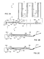
- FIG. 1A and 1B A schematic perspective full view of an extractor hood 10 is in the Figures 1A and 1B shown.
- the hood consists of a vent or chimney 11, a lower, firmly connected to the outlet shaft 11 hood part 12 and an extract 13, which is mounted in the horizontal direction movable in the manner of a drawer in the hood part 12 and / or on the exhaust duct 11.
- An extractor hood of this kind is installed, for example, over a stove.
- the exhaust duct 11 terminates in a port 111, which either opens into a pipeline or in air outlets (not shown), through which filtered air can be circulated back into the space with the cooking hob.
- a port 111 which either opens into a pipeline or in air outlets (not shown), through which filtered air can be circulated back into the space with the cooking hob.
- the fans or fans can be accommodated, suck the air from the bottom of the hood 10 and transport through the exhaust duct upwards.
- hood part 12 On the firmly connected hood part 12, primarily grease filters 121 are mounted, which close off the hood part 12 at least for the substantial part of its base area downwards. As shown, the grease filter may consist of one part or of several parallel part filters.
- the filter 121 is detachably mounted in the rigid hood part 12 and can be solved without tools for cleaning the hood part 12 and used again.
- the hood part may also have other operating and lighting elements 122, as partially in FIG FIG. 1B ande indicated.
- the drawer 13 consists essentially of a grip edge 131, a frame 132 and an insert 133 releasably secured in the frame.
- the insert 133 can be removed from the frame without tools by loosening an anchor 134 and cleaned as a separate part and again without tools be used.
- This insert is preferably designed as dishwasher-safe, eg completely made of stainless steel. It comprises essentially all parts of the drawer, where the haze or vapors are conducted past.
- the insert 133 forms at its front edge a gap 135 through which air is sucked in operation of the fan.
- This gap has substantially the same length as the insert 133.
- the gap 135 is largely free of lattice or sieve-shaped elements. Thereby and through one to possibly coarse grease filters as below with reference to FIG. 2B and 2C also described largely free air duct in the extract can be a strong extractor through the gap 135 reach even at a low overall height of the extract.
- the total height of the extension is 25 mm for extracts with a width of up to 50 cm, 55 cm or 60 cm and 30 mm for extracts from 60 to 90 cm or even up to 120 cm.
- the height of the drawer is determined in an area which excludes the front edge 131 with the handle. In order not to take into account local structures and shapes of the drawer 13, the height of the drawer 13 may be determined, for example, as an average value along the entire width of the insert 133 at about half the depth of the insert or a line parallel to that line.
- filter elements 112 are attached with activated carbon to allow recirculation mode.
- the filter elements are arranged vertically and form in the exhaust duct 11 smaller shafts, which are alternately closed at the bottom or top by plates, so that the air sucked from below flows transversely through the filter elements 112 to continue to rise in the chimney.
- the illustrated filter elements 112 also horizontally arranged or transversely arranged filter plates can be used.
- the exhaust duct 11 goes down into the wider, but also stationary mounted hood part 12, whose underside represents a vent opening, which is covered by a grease filter 121 during operation.
- This filter 121 is detachably but rigidly connected to a bottom plate of the hood part 12.
- the bottom plate also serves as a support for lamp sockets 122 and the stationary part of the suspension for the drawer 13th
- the drawer has a handle edge 131 at the front. This completes the frame 132 from the front.
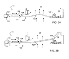
- the removable insert 133 consists of a ceiling portion 136 and a bottom portion 137, which constitute the upper and lower boundary surfaces for an air passage 138. In the example shown, both the ceiling part 136 and the bottom part 137 have no further openings, so that in the region of the air channel 138 itself no air can enter the channel.
- the ceiling part 136 has in the front part a downwardly bent front guide surface 136-1, the vertically rising air into the horizontal air passage 138 passes.
- the distance between the leading edges of the baffle 136-1 and the leading edge of the bottom portion 137 defines a downwardly open air gap 135 for the rim suction function of the hood 10.
- the bottom part 137 has at its trailing edge an obliquely upward rear guide surface 137-1. This improves the suction through the air duct 138 by means of the above the filter elements 112 mounted (and not shown) fan. With the design and surface of this rear guide surface 137-1 can be adjusted at least in an approximate mass, which part of the total suction generated by the suction motor in the exhaust duct 11 the air duct 138 and thus the air gap 135 in the extract 13 and for the intake through the grease filter 121 of the hood part 12 is provided.
- the distance between the ceiling part 136 and the bottom part 137 essentially defines the height of the air duct 138 or, with the restrictions already mentioned above, the height of the drawer 13.
- the extract is stored and dimensioned so that the bottom part 137 is pushed during insertion over the grease filter 121 and the extract 13 is thus in the inserted state thus substantially between the grease filter 121 and the chimney 11.
- the air passage 138 may be free of obstacles such as filter elements, which cause an additional pressure drop.
- the air duct has at least no extended structures between the bottom part 137 and the ceiling part 136, but is formed as smooth as possible.
- FIG. 2 B In the example of a modified drawer 13, the in FIG. 2 B is shown enlarged, however, in the region of the air channel 138, a lattice-shaped expanded metal 139 between the front edge of the ceiling portion 136 and the rear edge of the bottom portion 137 is clamped transversely to the air duct.
- This grid 139 serves to improve the grease separation and can be removed from the frame 132 with the entire insert 133 for cleaning become.
- the grid 139 is formed and mounted so that it restricts the air flow through the air duct 138 only slightly, for example, as expanded metal or simple single-layer perforated plate.
- the grid 139 is an expanded metal in wave form, which touches the ceiling part 136 with the wave crests and the bottom part 137 in the deepest part of the wave troughs.
- the grid 139 may be fixedly connected to the ceiling portion 136 and / or the floor portion 137, e.g. held by a weld or a screwed connection or by elastic action of the grid itself in the air duct.
- the grid may be continuous throughout the width of the drawer 13 or may be divided into segments, e.g. in parallel but staggered orientation or phase-shifted used strips which are parallel to the flow direction of the air in the air passage 138.
- the ceiling portion 136 and / or the bottom portion 137 may also include baffles, which extend only into the air passage 138 without completely bridge it. These baffles change the flow direction of the air sucked through the air duct 138 and thus lead to an improved separation of fat droplets from the intake air.
- the ceiling part 136 is provided with such an additional air guide plate 136-2, which extends obliquely into the air duct 138 and thus directs the air flowing substantially horizontally along the channel downwards in the direction of the bottom part 137.
- the additional air baffle 136-2 need not continuously span the entire width of the insert 133 and the air duct 138, but can also be shorter, for example, in the width and in the Depth staggered arranged Operaleit vom are formed, which taken together, the width at least substantially span, so that no part of the air flow without the desired deflection can pass through the zone with the baffles.
- the shorter in width sections may also be mounted, for example alternately on the ceiling part 136 and the bottom part 137.
- the bottom portion 137 of the insert 133 below the grease filter 121 is the bottom portion 137 of the insert 133 below the grease filter 121.
- the bottom part 137 is formed substantially as a smooth surface without a guide surface.
- the grease filter 121 is mounted on a level which is above the extract 13.
- the level is selected so that the rearward guide surface 137-1, which extends obliquely upwards, abuts against the rear edge of the bottom part 137 with its upper edge on the underside of the grease filter 121.
- the air sucked in through the air duct 138 passes on the way into the exhaust duct 11 a part of the grease filter 121 and is thus further cleaned of grease residues.
- the grease filter is not connected in this case with the bottom plate of the hood part 12, but mounted centrally or at the upper end of the hood part 12.
- the extract 13 and the grease filter 121 are not coupled, ie the grease filter remains stationary or fixed, even if the extract is moved.
- the grease filter is coupled either directly or indirectly to the drawer so that movement of the drape translates into movement of the filter or at least a portion of the filter.
- the grease filter is preferably moved so that it covers the lower opening of the hood in the mass in which it releases the extract during extension and insertion.
- the grease filter 121 is designed foldable.
- the filter 121 folds up during insertion of the drawer 13, in which the folding axis moves upwards along the middle of the filter.
- At the front edge of the filter 121 is pivotally connected to the drawer 13.
- At the rear edge of the filter 121 is connected in just such a manner with the bottom plate of the hood part 12.
- the grease filter 121 moves as a rigid unit when inserting the drawer 13 upwards in the hood part 12 and in the exhaust duct 11. At the front edge of the filter 121 is in turn hinged to the drawer 13. The trailing edge of the filter 121 moves upwardly along a path that may be defined by guide rails 123, for example.
- FIG. 2B or 2C or the additional baffles 136-2 FIG. 2D find application in all variants of the invention. It is therefore to be understood that the invention is not limited to the examples shown and may be practiced otherwise within the scope of the following claims.
Landscapes
- Engineering & Computer Science (AREA)
- Chemical & Material Sciences (AREA)
- Combustion & Propulsion (AREA)
- Mechanical Engineering (AREA)
- General Engineering & Computer Science (AREA)
- Ventilation (AREA)
Priority Applications (4)
| Application Number | Priority Date | Filing Date | Title |
|---|---|---|---|
| EP13003685.8A EP2829808B1 (fr) | 2013-07-23 | 2013-07-23 | Hotte aspirante |
| DK13003685.8T DK2829808T3 (en) | 2013-07-23 | 2013-07-23 | Extractor hood |
| SI201330455A SI2829808T1 (sl) | 2013-07-23 | 2013-07-23 | Napa za odvod pare |
| PL13003685T PL2829808T3 (pl) | 2013-07-23 | 2013-07-23 | Okap wyciągowy |
Applications Claiming Priority (1)
| Application Number | Priority Date | Filing Date | Title |
|---|---|---|---|
| EP13003685.8A EP2829808B1 (fr) | 2013-07-23 | 2013-07-23 | Hotte aspirante |
Publications (2)
| Publication Number | Publication Date |
|---|---|
| EP2829808A1 true EP2829808A1 (fr) | 2015-01-28 |
| EP2829808B1 EP2829808B1 (fr) | 2016-11-02 |
Family
ID=48875472
Family Applications (1)
| Application Number | Title | Priority Date | Filing Date |
|---|---|---|---|
| EP13003685.8A Active EP2829808B1 (fr) | 2013-07-23 | 2013-07-23 | Hotte aspirante |
Country Status (4)
| Country | Link |
|---|---|
| EP (1) | EP2829808B1 (fr) |
| DK (1) | DK2829808T3 (fr) |
| PL (1) | PL2829808T3 (fr) |
| SI (1) | SI2829808T1 (fr) |
Cited By (2)
| Publication number | Priority date | Publication date | Assignee | Title |
|---|---|---|---|---|
| DE102018129117A1 (de) * | 2018-11-20 | 2020-05-20 | Miele & Cie. Kg | Solitäre Wanddunstabzugshaube |
| EP4124800A1 (fr) * | 2021-07-26 | 2023-02-01 | ELICA S.p.A. | Hotte aspirante dotée d'une partie d'extraction |
Citations (8)
| Publication number | Priority date | Publication date | Assignee | Title |
|---|---|---|---|---|
| EP0443301A1 (fr) * | 1990-02-20 | 1991-08-28 | Aktiebolaget Electrolux | Ventilateur de cuisine |
| JPH03271646A (ja) * | 1990-03-19 | 1991-12-03 | Mitsubishi Electric Corp | レンジフード |
| EP0603637A1 (fr) | 1992-12-23 | 1994-06-29 | ZEO-TECH Zeolith Technologie GmbH | Cartouche avec agent de sorption |
| DE20316130U1 (de) * | 2003-10-21 | 2004-04-15 | BSH Bosch und Siemens Hausgeräte GmbH | Satz von Schubladen-Dunstabzugshauben |
| EP1624254A1 (fr) | 2004-08-04 | 2006-02-08 | V-Zug AG | Hotte d'aspiration à placer au-dessus d'un plan de cuisson |
| JP2007192484A (ja) * | 2006-01-20 | 2007-08-02 | Hitachi Appliances Inc | レンジフード |
| JP2007232369A (ja) * | 2007-06-18 | 2007-09-13 | Matsushita Electric Ind Co Ltd | レンジフード |
| EP1842008A1 (fr) | 2005-01-17 | 2007-10-10 | BSH Bosch und Siemens Hausgeräte GmbH | Dispositif d'aspiration pour vapeurs de cuisine |
-
2013
- 2013-07-23 DK DK13003685.8T patent/DK2829808T3/en active
- 2013-07-23 PL PL13003685T patent/PL2829808T3/pl unknown
- 2013-07-23 EP EP13003685.8A patent/EP2829808B1/fr active Active
- 2013-07-23 SI SI201330455A patent/SI2829808T1/sl unknown
Patent Citations (8)
| Publication number | Priority date | Publication date | Assignee | Title |
|---|---|---|---|---|
| EP0443301A1 (fr) * | 1990-02-20 | 1991-08-28 | Aktiebolaget Electrolux | Ventilateur de cuisine |
| JPH03271646A (ja) * | 1990-03-19 | 1991-12-03 | Mitsubishi Electric Corp | レンジフード |
| EP0603637A1 (fr) | 1992-12-23 | 1994-06-29 | ZEO-TECH Zeolith Technologie GmbH | Cartouche avec agent de sorption |
| DE20316130U1 (de) * | 2003-10-21 | 2004-04-15 | BSH Bosch und Siemens Hausgeräte GmbH | Satz von Schubladen-Dunstabzugshauben |
| EP1624254A1 (fr) | 2004-08-04 | 2006-02-08 | V-Zug AG | Hotte d'aspiration à placer au-dessus d'un plan de cuisson |
| EP1842008A1 (fr) | 2005-01-17 | 2007-10-10 | BSH Bosch und Siemens Hausgeräte GmbH | Dispositif d'aspiration pour vapeurs de cuisine |
| JP2007192484A (ja) * | 2006-01-20 | 2007-08-02 | Hitachi Appliances Inc | レンジフード |
| JP2007232369A (ja) * | 2007-06-18 | 2007-09-13 | Matsushita Electric Ind Co Ltd | レンジフード |
Cited By (2)
| Publication number | Priority date | Publication date | Assignee | Title |
|---|---|---|---|---|
| DE102018129117A1 (de) * | 2018-11-20 | 2020-05-20 | Miele & Cie. Kg | Solitäre Wanddunstabzugshaube |
| EP4124800A1 (fr) * | 2021-07-26 | 2023-02-01 | ELICA S.p.A. | Hotte aspirante dotée d'une partie d'extraction |
Also Published As
| Publication number | Publication date |
|---|---|
| DK2829808T3 (en) | 2017-02-06 |
| EP2829808B1 (fr) | 2016-11-02 |
| PL2829808T3 (pl) | 2017-03-31 |
| SI2829808T1 (sl) | 2017-01-31 |
Similar Documents
| Publication | Publication Date | Title |
|---|---|---|
| EP3869107B1 (fr) | Plaque de cuisson | |
| DE102013007722B4 (de) | Muldenlüftung zum Abzug von Kochdampf an einem Kochfeld | |
| EP3475622B1 (fr) | Système de ventilation à courant descendant avec un insert | |
| EP3045824B1 (fr) | Dispositif d'aspiration d'air d'une cuisiniere | |
| EP1194721B1 (fr) | Dispositif d'aspiration d'air pour poste de travail | |
| DE102005030038B4 (de) | Kochfeldabzugsvorrichtung | |
| DE2323596A1 (de) | Verfahren zur filterung von fetthaltigen daempfen und filtereinsatz fuer wrasenabzug | |
| DE102006055001A1 (de) | Dunstabsaugeinrichtung | |
| DE102008020149A1 (de) | Filtereinheit für eine Dunstabzugsvorrichtung und Dunstabzugsvorrichtung | |
| DE202018006721U1 (de) | Dunstabzug zum Abzug von auf einem Kochfeld erzeugter Abluft in vertikal unterhalb einer Kochfeldebene weisender Richtung | |
| DE1924345A1 (de) | Dunstabzugshaube | |
| WO2005100863A1 (fr) | Dispositif d'aspiration de fumees pour systeme de preparation d'aliments | |
| EP2772695B1 (fr) | Hotte aspirante | |
| EP2334988B1 (fr) | Hotte aspirante | |
| EP2210048B1 (fr) | Dispositif d'aspiration de vapeurs | |
| EP2857758A1 (fr) | Dispositif d'aspiration de vapeur | |
| EP2829808B1 (fr) | Hotte aspirante | |
| DE202015104361U1 (de) | Dunstabzugshaube für ein Gargerät sowie Gargerät mit einer solchen Dunstabzugshaube | |
| EP2677242A1 (fr) | Dispositif de déviation d'air | |
| EP1128132B1 (fr) | Hotte aspirant la buée | |
| DE202005010164U1 (de) | Kochfeldabzugsvorrichtung | |
| DE2231845C3 (de) | Dunstabzugshaube | |
| DE19950817A1 (de) | Dunstabzugsvorrichtung | |
| EP2615383B1 (fr) | Hotte aspirante | |
| EP1846699A1 (fr) | Dispositif d'evacuation de fumees pour la cuisine |
Legal Events
| Date | Code | Title | Description |
|---|---|---|---|
| 17P | Request for examination filed |
Effective date: 20130723 |
|
| AK | Designated contracting states |
Kind code of ref document: A1 Designated state(s): AL AT BE BG CH CY CZ DE DK EE ES FI FR GB GR HR HU IE IS IT LI LT LU LV MC MK MT NL NO PL PT RO RS SE SI SK SM TR |
|
| AX | Request for extension of the european patent |
Extension state: BA ME |
|
| PUAI | Public reference made under article 153(3) epc to a published international application that has entered the european phase |
Free format text: ORIGINAL CODE: 0009012 |
|
| R17P | Request for examination filed (corrected) |
Effective date: 20150727 |
|
| RBV | Designated contracting states (corrected) |
Designated state(s): AL AT BE BG CH CY CZ DE DK EE ES FI FR GB GR HR HU IE IS IT LI LT LU LV MC MK MT NL NO PL PT RO RS SE SI SK SM TR |
|
| GRAP | Despatch of communication of intention to grant a patent |
Free format text: ORIGINAL CODE: EPIDOSNIGR1 |
|
| INTG | Intention to grant announced |
Effective date: 20160610 |
|
| GRAS | Grant fee paid |
Free format text: ORIGINAL CODE: EPIDOSNIGR3 |
|
| GRAA | (expected) grant |
Free format text: ORIGINAL CODE: 0009210 |
|
| AK | Designated contracting states |
Kind code of ref document: B1 Designated state(s): AL AT BE BG CH CY CZ DE DK EE ES FI FR GB GR HR HU IE IS IT LI LT LU LV MC MK MT NL NO PL PT RO RS SE SI SK SM TR |
|
| REG | Reference to a national code |
Ref country code: GB Ref legal event code: FG4D Free format text: NOT ENGLISH |
|
| REG | Reference to a national code |
Ref country code: AT Ref legal event code: REF Ref document number: 842238 Country of ref document: AT Kind code of ref document: T Effective date: 20161115 Ref country code: CH Ref legal event code: EP Ref country code: CH Ref legal event code: NV Representative=s name: E. BLUM AND CO. AG PATENT- UND MARKENANWAELTE , CH |
|
| REG | Reference to a national code |
Ref country code: IE Ref legal event code: FG4D Free format text: LANGUAGE OF EP DOCUMENT: GERMAN |
|
| REG | Reference to a national code |
Ref country code: DE Ref legal event code: R096 Ref document number: 502013005139 Country of ref document: DE |
|
| REG | Reference to a national code |
Ref country code: DK Ref legal event code: T3 Effective date: 20170131 |
|
| REG | Reference to a national code |
Ref country code: SE Ref legal event code: TRGR |
|
| PG25 | Lapsed in a contracting state [announced via postgrant information from national office to epo] |
Ref country code: LV Free format text: LAPSE BECAUSE OF FAILURE TO SUBMIT A TRANSLATION OF THE DESCRIPTION OR TO PAY THE FEE WITHIN THE PRESCRIBED TIME-LIMIT Effective date: 20161102 |
|
| REG | Reference to a national code |
Ref country code: NL Ref legal event code: MP Effective date: 20161102 |
|
| REG | Reference to a national code |
Ref country code: LT Ref legal event code: MG4D |
|
| PG25 | Lapsed in a contracting state [announced via postgrant information from national office to epo] |
Ref country code: GR Free format text: LAPSE BECAUSE OF FAILURE TO SUBMIT A TRANSLATION OF THE DESCRIPTION OR TO PAY THE FEE WITHIN THE PRESCRIBED TIME-LIMIT Effective date: 20170203 Ref country code: NL Free format text: LAPSE BECAUSE OF FAILURE TO SUBMIT A TRANSLATION OF THE DESCRIPTION OR TO PAY THE FEE WITHIN THE PRESCRIBED TIME-LIMIT Effective date: 20161102 Ref country code: NO Free format text: LAPSE BECAUSE OF FAILURE TO SUBMIT A TRANSLATION OF THE DESCRIPTION OR TO PAY THE FEE WITHIN THE PRESCRIBED TIME-LIMIT Effective date: 20170202 Ref country code: LT Free format text: LAPSE BECAUSE OF FAILURE TO SUBMIT A TRANSLATION OF THE DESCRIPTION OR TO PAY THE FEE WITHIN THE PRESCRIBED TIME-LIMIT Effective date: 20161102 |
|
| PG25 | Lapsed in a contracting state [announced via postgrant information from national office to epo] |
Ref country code: IS Free format text: LAPSE BECAUSE OF FAILURE TO SUBMIT A TRANSLATION OF THE DESCRIPTION OR TO PAY THE FEE WITHIN THE PRESCRIBED TIME-LIMIT Effective date: 20170302 Ref country code: PT Free format text: LAPSE BECAUSE OF FAILURE TO SUBMIT A TRANSLATION OF THE DESCRIPTION OR TO PAY THE FEE WITHIN THE PRESCRIBED TIME-LIMIT Effective date: 20170302 Ref country code: HR Free format text: LAPSE BECAUSE OF FAILURE TO SUBMIT A TRANSLATION OF THE DESCRIPTION OR TO PAY THE FEE WITHIN THE PRESCRIBED TIME-LIMIT Effective date: 20161102 Ref country code: ES Free format text: LAPSE BECAUSE OF FAILURE TO SUBMIT A TRANSLATION OF THE DESCRIPTION OR TO PAY THE FEE WITHIN THE PRESCRIBED TIME-LIMIT Effective date: 20161102 Ref country code: RS Free format text: LAPSE BECAUSE OF FAILURE TO SUBMIT A TRANSLATION OF THE DESCRIPTION OR TO PAY THE FEE WITHIN THE PRESCRIBED TIME-LIMIT Effective date: 20161102 Ref country code: FI Free format text: LAPSE BECAUSE OF FAILURE TO SUBMIT A TRANSLATION OF THE DESCRIPTION OR TO PAY THE FEE WITHIN THE PRESCRIBED TIME-LIMIT Effective date: 20161102 |
|
| REG | Reference to a national code |
Ref country code: FR Ref legal event code: PLFP Year of fee payment: 5 |
|
| PG25 | Lapsed in a contracting state [announced via postgrant information from national office to epo] |
Ref country code: SK Free format text: LAPSE BECAUSE OF FAILURE TO SUBMIT A TRANSLATION OF THE DESCRIPTION OR TO PAY THE FEE WITHIN THE PRESCRIBED TIME-LIMIT Effective date: 20161102 Ref country code: EE Free format text: LAPSE BECAUSE OF FAILURE TO SUBMIT A TRANSLATION OF THE DESCRIPTION OR TO PAY THE FEE WITHIN THE PRESCRIBED TIME-LIMIT Effective date: 20161102 Ref country code: CZ Free format text: LAPSE BECAUSE OF FAILURE TO SUBMIT A TRANSLATION OF THE DESCRIPTION OR TO PAY THE FEE WITHIN THE PRESCRIBED TIME-LIMIT Effective date: 20161102 Ref country code: RO Free format text: LAPSE BECAUSE OF FAILURE TO SUBMIT A TRANSLATION OF THE DESCRIPTION OR TO PAY THE FEE WITHIN THE PRESCRIBED TIME-LIMIT Effective date: 20161102 |
|
| REG | Reference to a national code |
Ref country code: DE Ref legal event code: R082 Ref document number: 502013005139 Country of ref document: DE Representative=s name: KLUNKER IP PATENTANWAELTE PARTG MBB, DE |
|
| REG | Reference to a national code |
Ref country code: DE Ref legal event code: R097 Ref document number: 502013005139 Country of ref document: DE |
|
| PG25 | Lapsed in a contracting state [announced via postgrant information from national office to epo] |
Ref country code: IT Free format text: LAPSE BECAUSE OF FAILURE TO SUBMIT A TRANSLATION OF THE DESCRIPTION OR TO PAY THE FEE WITHIN THE PRESCRIBED TIME-LIMIT Effective date: 20161102 Ref country code: BG Free format text: LAPSE BECAUSE OF FAILURE TO SUBMIT A TRANSLATION OF THE DESCRIPTION OR TO PAY THE FEE WITHIN THE PRESCRIBED TIME-LIMIT Effective date: 20170202 Ref country code: SM Free format text: LAPSE BECAUSE OF FAILURE TO SUBMIT A TRANSLATION OF THE DESCRIPTION OR TO PAY THE FEE WITHIN THE PRESCRIBED TIME-LIMIT Effective date: 20161102 |
|
| PLBE | No opposition filed within time limit |
Free format text: ORIGINAL CODE: 0009261 |
|
| STAA | Information on the status of an ep patent application or granted ep patent |
Free format text: STATUS: NO OPPOSITION FILED WITHIN TIME LIMIT |
|
| 26N | No opposition filed |
Effective date: 20170803 |
|
| REG | Reference to a national code |
Ref country code: IE Ref legal event code: MM4A |
|
| PG25 | Lapsed in a contracting state [announced via postgrant information from national office to epo] |
Ref country code: IE Free format text: LAPSE BECAUSE OF NON-PAYMENT OF DUE FEES Effective date: 20170723 |
|
| REG | Reference to a national code |
Ref country code: BE Ref legal event code: MM Effective date: 20170731 |
|
| PG25 | Lapsed in a contracting state [announced via postgrant information from national office to epo] |
Ref country code: LU Free format text: LAPSE BECAUSE OF NON-PAYMENT OF DUE FEES Effective date: 20170723 |
|
| REG | Reference to a national code |
Ref country code: FR Ref legal event code: PLFP Year of fee payment: 6 |
|
| PG25 | Lapsed in a contracting state [announced via postgrant information from national office to epo] |
Ref country code: BE Free format text: LAPSE BECAUSE OF NON-PAYMENT OF DUE FEES Effective date: 20170731 |
|
| REG | Reference to a national code |
Ref country code: SI Ref legal event code: SP73 Owner name: V-ZUG AG; CH Effective date: 20180629 |
|
| PG25 | Lapsed in a contracting state [announced via postgrant information from national office to epo] |
Ref country code: MT Free format text: LAPSE BECAUSE OF FAILURE TO SUBMIT A TRANSLATION OF THE DESCRIPTION OR TO PAY THE FEE WITHIN THE PRESCRIBED TIME-LIMIT Effective date: 20161102 |
|
| PG25 | Lapsed in a contracting state [announced via postgrant information from national office to epo] |
Ref country code: MC Free format text: LAPSE BECAUSE OF FAILURE TO SUBMIT A TRANSLATION OF THE DESCRIPTION OR TO PAY THE FEE WITHIN THE PRESCRIBED TIME-LIMIT Effective date: 20161102 Ref country code: HU Free format text: LAPSE BECAUSE OF FAILURE TO SUBMIT A TRANSLATION OF THE DESCRIPTION OR TO PAY THE FEE WITHIN THE PRESCRIBED TIME-LIMIT; INVALID AB INITIO Effective date: 20130723 |
|
| PGFP | Annual fee paid to national office [announced via postgrant information from national office to epo] |
Ref country code: PL Payment date: 20190625 Year of fee payment: 7 |
|
| REG | Reference to a national code |
Ref country code: AT Ref legal event code: MM01 Ref document number: 842238 Country of ref document: AT Kind code of ref document: T Effective date: 20180723 |
|
| PG25 | Lapsed in a contracting state [announced via postgrant information from national office to epo] |
Ref country code: CY Free format text: LAPSE BECAUSE OF FAILURE TO SUBMIT A TRANSLATION OF THE DESCRIPTION OR TO PAY THE FEE WITHIN THE PRESCRIBED TIME-LIMIT Effective date: 20161102 |
|
| PGFP | Annual fee paid to national office [announced via postgrant information from national office to epo] |
Ref country code: DK Payment date: 20190723 Year of fee payment: 7 Ref country code: FR Payment date: 20190719 Year of fee payment: 7 |
|
| PG25 | Lapsed in a contracting state [announced via postgrant information from national office to epo] |
Ref country code: MK Free format text: LAPSE BECAUSE OF FAILURE TO SUBMIT A TRANSLATION OF THE DESCRIPTION OR TO PAY THE FEE WITHIN THE PRESCRIBED TIME-LIMIT Effective date: 20161102 |
|
| PG25 | Lapsed in a contracting state [announced via postgrant information from national office to epo] |
Ref country code: AT Free format text: LAPSE BECAUSE OF NON-PAYMENT OF DUE FEES Effective date: 20180723 |
|
| PGFP | Annual fee paid to national office [announced via postgrant information from national office to epo] |
Ref country code: GB Payment date: 20190719 Year of fee payment: 7 |
|
| PG25 | Lapsed in a contracting state [announced via postgrant information from national office to epo] |
Ref country code: TR Free format text: LAPSE BECAUSE OF FAILURE TO SUBMIT A TRANSLATION OF THE DESCRIPTION OR TO PAY THE FEE WITHIN THE PRESCRIBED TIME-LIMIT Effective date: 20161102 |
|
| PG25 | Lapsed in a contracting state [announced via postgrant information from national office to epo] |
Ref country code: AL Free format text: LAPSE BECAUSE OF FAILURE TO SUBMIT A TRANSLATION OF THE DESCRIPTION OR TO PAY THE FEE WITHIN THE PRESCRIBED TIME-LIMIT Effective date: 20161102 |
|
| REG | Reference to a national code |
Ref country code: DK Ref legal event code: EBP Effective date: 20200731 |
|
| GBPC | Gb: european patent ceased through non-payment of renewal fee |
Effective date: 20200723 |
|
| PG25 | Lapsed in a contracting state [announced via postgrant information from national office to epo] |
Ref country code: FR Free format text: LAPSE BECAUSE OF NON-PAYMENT OF DUE FEES Effective date: 20200731 Ref country code: GB Free format text: LAPSE BECAUSE OF NON-PAYMENT OF DUE FEES Effective date: 20200723 |
|
| PG25 | Lapsed in a contracting state [announced via postgrant information from national office to epo] |
Ref country code: DK Free format text: LAPSE BECAUSE OF NON-PAYMENT OF DUE FEES Effective date: 20200731 |
|
| PG25 | Lapsed in a contracting state [announced via postgrant information from national office to epo] |
Ref country code: PL Free format text: LAPSE BECAUSE OF NON-PAYMENT OF DUE FEES Effective date: 20200723 |
|
| P01 | Opt-out of the competence of the unified patent court (upc) registered |
Effective date: 20230426 |
|
| PGFP | Annual fee paid to national office [announced via postgrant information from national office to epo] |
Ref country code: CH Payment date: 20230801 Year of fee payment: 11 |
|
| PGFP | Annual fee paid to national office [announced via postgrant information from national office to epo] |
Ref country code: SI Payment date: 20230713 Year of fee payment: 11 Ref country code: SE Payment date: 20230719 Year of fee payment: 11 Ref country code: DE Payment date: 20230719 Year of fee payment: 11 |