EP2829226B1 - Canule de perfusion à technique sensorielle intégrée - Google Patents
Canule de perfusion à technique sensorielle intégrée Download PDFInfo
- Publication number
- EP2829226B1 EP2829226B1 EP13003716.1A EP13003716A EP2829226B1 EP 2829226 B1 EP2829226 B1 EP 2829226B1 EP 13003716 A EP13003716 A EP 13003716A EP 2829226 B1 EP2829226 B1 EP 2829226B1
- Authority
- EP
- European Patent Office
- Prior art keywords
- cannula
- sensor
- perfusion
- perfusion cannula
- lumen
- Prior art date
- Legal status (The legal status is an assumption and is not a legal conclusion. Google has not performed a legal analysis and makes no representation as to the accuracy of the status listed.)
- Active
Links
- 230000010412 perfusion Effects 0.000 title claims description 187
- 238000003780 insertion Methods 0.000 claims description 17
- 230000037431 insertion Effects 0.000 claims description 17
- 239000012530 fluid Substances 0.000 claims description 15
- 229920002635 polyurethane Polymers 0.000 claims description 15
- 239000004814 polyurethane Substances 0.000 claims description 15
- 230000002787 reinforcement Effects 0.000 claims description 13
- 229920001296 polysiloxane Polymers 0.000 claims description 6
- 239000000523 sample Substances 0.000 claims description 5
- 239000004020 conductor Substances 0.000 claims description 4
- 239000000835 fiber Substances 0.000 claims description 3
- 230000004087 circulation Effects 0.000 claims description 2
- 239000011527 polyurethane coating Substances 0.000 claims description 2
- 229920000915 polyvinyl chloride Polymers 0.000 claims description 2
- 229910000831 Steel Inorganic materials 0.000 claims 1
- 238000010276 construction Methods 0.000 claims 1
- 239000010959 steel Substances 0.000 claims 1
- 238000005259 measurement Methods 0.000 description 22
- 210000002216 heart Anatomy 0.000 description 15
- 239000008280 blood Substances 0.000 description 11
- 210000004369 blood Anatomy 0.000 description 11
- 241001631457 Cannula Species 0.000 description 10
- 210000001367 artery Anatomy 0.000 description 10
- 238000011156 evaluation Methods 0.000 description 9
- 238000009530 blood pressure measurement Methods 0.000 description 8
- 210000004013 groin Anatomy 0.000 description 7
- 230000036772 blood pressure Effects 0.000 description 6
- 230000035939 shock Effects 0.000 description 6
- 230000000747 cardiac effect Effects 0.000 description 5
- 238000000576 coating method Methods 0.000 description 5
- 210000004072 lung Anatomy 0.000 description 5
- 238000004519 manufacturing process Methods 0.000 description 5
- 239000000463 material Substances 0.000 description 5
- 210000002376 aorta thoracic Anatomy 0.000 description 4
- 239000011248 coating agent Substances 0.000 description 4
- 210000000056 organ Anatomy 0.000 description 4
- 210000003462 vein Anatomy 0.000 description 4
- 241001465754 Metazoa Species 0.000 description 3
- 206010047139 Vasoconstriction Diseases 0.000 description 3
- 238000005452 bending Methods 0.000 description 3
- 229920000642 polymer Polymers 0.000 description 3
- 230000007704 transition Effects 0.000 description 3
- XLYOFNOQVPJJNP-UHFFFAOYSA-N water Substances O XLYOFNOQVPJJNP-UHFFFAOYSA-N 0.000 description 3
- CURLTUGMZLYLDI-UHFFFAOYSA-N Carbon dioxide Chemical compound O=C=O CURLTUGMZLYLDI-UHFFFAOYSA-N 0.000 description 2
- 239000000853 adhesive Substances 0.000 description 2
- 230000001070 adhesive effect Effects 0.000 description 2
- 210000000709 aorta Anatomy 0.000 description 2
- QVGXLLKOCUKJST-UHFFFAOYSA-N atomic oxygen Chemical compound [O] QVGXLLKOCUKJST-UHFFFAOYSA-N 0.000 description 2
- 210000000038 chest Anatomy 0.000 description 2
- 238000007598 dipping method Methods 0.000 description 2
- 230000000694 effects Effects 0.000 description 2
- 238000001125 extrusion Methods 0.000 description 2
- 239000012528 membrane Substances 0.000 description 2
- 238000000034 method Methods 0.000 description 2
- 238000012544 monitoring process Methods 0.000 description 2
- 229910052760 oxygen Inorganic materials 0.000 description 2
- 239000001301 oxygen Substances 0.000 description 2
- 230000002093 peripheral effect Effects 0.000 description 2
- 238000009256 replacement therapy Methods 0.000 description 2
- 230000002792 vascular Effects 0.000 description 2
- 230000025033 vasoconstriction Effects 0.000 description 2
- 210000002620 vena cava superior Anatomy 0.000 description 2
- 206010053567 Coagulopathies Diseases 0.000 description 1
- 208000005189 Embolism Diseases 0.000 description 1
- 230000003187 abdominal effect Effects 0.000 description 1
- 239000002390 adhesive tape Substances 0.000 description 1
- 230000003416 augmentation Effects 0.000 description 1
- 239000000560 biocompatible material Substances 0.000 description 1
- 230000017531 blood circulation Effects 0.000 description 1
- 239000003633 blood substitute Substances 0.000 description 1
- 229910002092 carbon dioxide Inorganic materials 0.000 description 1
- 239000001569 carbon dioxide Substances 0.000 description 1
- 230000001269 cardiogenic effect Effects 0.000 description 1
- 230000035602 clotting Effects 0.000 description 1
- 230000003205 diastolic effect Effects 0.000 description 1
- 239000013013 elastic material Substances 0.000 description 1
- 238000005516 engineering process Methods 0.000 description 1
- 239000007789 gas Substances 0.000 description 1
- 239000011521 glass Substances 0.000 description 1
- 210000002837 heart atrium Anatomy 0.000 description 1
- 230000001771 impaired effect Effects 0.000 description 1
- 238000002847 impedance measurement Methods 0.000 description 1
- 238000001727 in vivo Methods 0.000 description 1
- 238000009434 installation Methods 0.000 description 1
- 230000002452 interceptive effect Effects 0.000 description 1
- 210000002414 leg Anatomy 0.000 description 1
- 239000007788 liquid Substances 0.000 description 1
- 210000004165 myocardium Anatomy 0.000 description 1
- 238000005192 partition Methods 0.000 description 1
- 229920003023 plastic Polymers 0.000 description 1
- 239000004033 plastic Substances 0.000 description 1
- 239000011343 solid material Substances 0.000 description 1
- 229910001220 stainless steel Inorganic materials 0.000 description 1
- 239000010935 stainless steel Substances 0.000 description 1
- 210000002784 stomach Anatomy 0.000 description 1
- 238000002560 therapeutic procedure Methods 0.000 description 1
- 210000000115 thoracic cavity Anatomy 0.000 description 1
- 210000001519 tissue Anatomy 0.000 description 1
- 230000000472 traumatic effect Effects 0.000 description 1
- 230000001960 triggered effect Effects 0.000 description 1
- 210000000689 upper leg Anatomy 0.000 description 1
- 210000000707 wrist Anatomy 0.000 description 1
Images


Classifications
-
- A—HUMAN NECESSITIES
- A61—MEDICAL OR VETERINARY SCIENCE; HYGIENE
- A61B—DIAGNOSIS; SURGERY; IDENTIFICATION
- A61B5/00—Measuring for diagnostic purposes; Identification of persons
- A61B5/68—Arrangements of detecting, measuring or recording means, e.g. sensors, in relation to patient
- A61B5/6846—Arrangements of detecting, measuring or recording means, e.g. sensors, in relation to patient specially adapted to be brought in contact with an internal body part, i.e. invasive
- A61B5/6847—Arrangements of detecting, measuring or recording means, e.g. sensors, in relation to patient specially adapted to be brought in contact with an internal body part, i.e. invasive mounted on an invasive device
- A61B5/6866—Extracorporeal blood circuits, e.g. dialysis circuits
-
- A—HUMAN NECESSITIES
- A61—MEDICAL OR VETERINARY SCIENCE; HYGIENE
- A61B—DIAGNOSIS; SURGERY; IDENTIFICATION
- A61B5/00—Measuring for diagnostic purposes; Identification of persons
- A61B5/24—Detecting, measuring or recording bioelectric or biomagnetic signals of the body or parts thereof
- A61B5/25—Bioelectric electrodes therefor
- A61B5/279—Bioelectric electrodes therefor specially adapted for particular uses
- A61B5/28—Bioelectric electrodes therefor specially adapted for particular uses for electrocardiography [ECG]
- A61B5/283—Invasive
-
- A—HUMAN NECESSITIES
- A61—MEDICAL OR VETERINARY SCIENCE; HYGIENE
- A61B—DIAGNOSIS; SURGERY; IDENTIFICATION
- A61B5/00—Measuring for diagnostic purposes; Identification of persons
- A61B5/02—Detecting, measuring or recording pulse, heart rate, blood pressure or blood flow; Combined pulse/heart-rate/blood pressure determination; Evaluating a cardiovascular condition not otherwise provided for, e.g. using combinations of techniques provided for in this group with electrocardiography or electroauscultation; Heart catheters for measuring blood pressure
- A61B5/021—Measuring pressure in heart or blood vessels
- A61B5/0215—Measuring pressure in heart or blood vessels by means inserted into the body
- A61B5/02154—Measuring pressure in heart or blood vessels by means inserted into the body by optical transmission
-
- A—HUMAN NECESSITIES
- A61—MEDICAL OR VETERINARY SCIENCE; HYGIENE
- A61B—DIAGNOSIS; SURGERY; IDENTIFICATION
- A61B5/00—Measuring for diagnostic purposes; Identification of persons
- A61B5/24—Detecting, measuring or recording bioelectric or biomagnetic signals of the body or parts thereof
- A61B5/25—Bioelectric electrodes therefor
- A61B5/279—Bioelectric electrodes therefor specially adapted for particular uses
- A61B5/28—Bioelectric electrodes therefor specially adapted for particular uses for electrocardiography [ECG]
- A61B5/283—Invasive
- A61B5/287—Holders for multiple electrodes, e.g. electrode catheters for electrophysiological study [EPS]
-
- A—HUMAN NECESSITIES
- A61—MEDICAL OR VETERINARY SCIENCE; HYGIENE
- A61M—DEVICES FOR INTRODUCING MEDIA INTO, OR ONTO, THE BODY; DEVICES FOR TRANSDUCING BODY MEDIA OR FOR TAKING MEDIA FROM THE BODY; DEVICES FOR PRODUCING OR ENDING SLEEP OR STUPOR
- A61M1/00—Suction or pumping devices for medical purposes; Devices for carrying-off, for treatment of, or for carrying-over, body-liquids; Drainage systems
- A61M1/36—Other treatment of blood in a by-pass of the natural circulatory system, e.g. temperature adaptation, irradiation ; Extra-corporeal blood circuits
- A61M1/3621—Extra-corporeal blood circuits
- A61M1/3653—Interfaces between patient blood circulation and extra-corporal blood circuit
- A61M1/3659—Cannulae pertaining to extracorporeal circulation
-
- A—HUMAN NECESSITIES
- A61—MEDICAL OR VETERINARY SCIENCE; HYGIENE
- A61B—DIAGNOSIS; SURGERY; IDENTIFICATION
- A61B2562/00—Details of sensors; Constructional details of sensor housings or probes; Accessories for sensors
- A61B2562/22—Arrangements of medical sensors with cables or leads; Connectors or couplings specifically adapted for medical sensors
- A61B2562/221—Arrangements of sensors with cables or leads, e.g. cable harnesses
- A61B2562/223—Optical cables therefor
-
- A—HUMAN NECESSITIES
- A61—MEDICAL OR VETERINARY SCIENCE; HYGIENE
- A61M—DEVICES FOR INTRODUCING MEDIA INTO, OR ONTO, THE BODY; DEVICES FOR TRANSDUCING BODY MEDIA OR FOR TAKING MEDIA FROM THE BODY; DEVICES FOR PRODUCING OR ENDING SLEEP OR STUPOR
- A61M25/00—Catheters; Hollow probes
- A61M2025/0001—Catheters; Hollow probes for pressure measurement
- A61M2025/0002—Catheters; Hollow probes for pressure measurement with a pressure sensor at the distal end
-
- A—HUMAN NECESSITIES
- A61—MEDICAL OR VETERINARY SCIENCE; HYGIENE
- A61M—DEVICES FOR INTRODUCING MEDIA INTO, OR ONTO, THE BODY; DEVICES FOR TRANSDUCING BODY MEDIA OR FOR TAKING MEDIA FROM THE BODY; DEVICES FOR PRODUCING OR ENDING SLEEP OR STUPOR
- A61M2205/00—General characteristics of the apparatus
- A61M2205/33—Controlling, regulating or measuring
- A61M2205/3331—Pressure; Flow
- A61M2205/3344—Measuring or controlling pressure at the body treatment site
-
- A—HUMAN NECESSITIES
- A61—MEDICAL OR VETERINARY SCIENCE; HYGIENE
- A61M—DEVICES FOR INTRODUCING MEDIA INTO, OR ONTO, THE BODY; DEVICES FOR TRANSDUCING BODY MEDIA OR FOR TAKING MEDIA FROM THE BODY; DEVICES FOR PRODUCING OR ENDING SLEEP OR STUPOR
- A61M2230/00—Measuring parameters of the user
- A61M2230/04—Heartbeat characteristics, e.g. ECG, blood pressure modulation
Definitions
- the invention relates to a perfusion cannula according to the preamble of claim 1 for laying an arterial or venous access, in particular in connection with a circulatory replacement therapy.
- Circulatory replacement therapy can take place, for example, by means of an extracorporeal lung support system, by means of which blood or a fluid replacing the blood is taken from a patient at one point (especially venous) and fed back to another point (especially arterial) after it has been enriched with oxygen and / or the level of carbon dioxide therein has been reduced.
- So-called membrane fans which are also referred to as membrane oxygenators, can be used for this purpose.
- the blood / fluid can be withdrawn or supplied by means of cannulas.
- perfusion refers to the supply of organs with blood. Organ perfusion occurs naturally via arteries and veins, but can also take place artificially, e.g. via bypasses or extracorporeal lines that can be connected to the organism by means of perfusion cannulas. Perfusion cannulas are often used for arterial puncture, but also as venous perfusion cannulas. They provide a supply channel through which a fluid (e.g. blood or a blood substitute) can be supplied or removed. Perfusion cannulas are used, for example, in shock situations in humans or animals. In shock situations, monitoring of the vital status is also of great importance.
- a fluid e.g. blood or a blood substitute
- an electrocardiogram can be created, i.e. a cardiac voltage curve.
- the electrocardiogram is usually recorded via an impedance measurement by means of (adhesive) electrodes attached to the skin of the person / animal (hereinafter “patient”).
- An EKG measurement is made more difficult, for example, by high skin resistance or by adhesive electrodes that do not adhere adequately to the skin (especially due to damp skin). There is also the risk that the skin will be injured by the electrodes.
- the measurement is also made more difficult by the fact that the electrodes can slip, which can be a major problem in the event of resistance or unstable positioning of a patient.
- Blood pressure can be measured in an invasive manner, for example, by using a cannula to record a pressure in one of the patient's peripheral arteries, e.g. an artery in the arm or leg.
- a pressure measurement requires a separate pressure measurement system in which the pressure is recorded via a water column to a pressure measurement system and is fed to a monitoring system for checking vital functions or for diagnosing the patient.
- peripheral vasoconstriction vaconstriction
- the cannulation required for this pressure measurement can usually only be placed with difficulty because the preferred places on the wrists and elbows are severely narrowed, or because inguinal vessels are occupied by extracorporeal procedures.
- U.S. 5,029,585 A discloses electrodes for use with medical catheters.
- the catheter has a cannula wall and a perfusion volume delimited by the cannula wall.
- a sensor lumen is provided.
- U.S. 5,433,742 A describes cardiac catheters that can have adhesive tape electrodes.
- US 2002/111662 A1 describes an implantable medical device that is expandable and may include a pressure sensor. An EKG sensor can be provided.
- US 2011/092955 A1 discloses a perfusion cannula with a cannula wall defining a perfusion lumen.
- a sensor lumen and a sensor device can be provided.
- the document US 2010/0094255 A1 describes a cannulated sensor device having a proximal and a distal end.
- WO 00/57805 A1 describes a cannula with a pressure sensor for measuring the fluid pressure.
- the perfusion cannula should preferably enable safe handling and / or be able to perform functions in a particularly reliable manner. More preferably, the device should also be robust with regard to interfering influences.
- At least one of the aforementioned objects is achieved by a perfusion cannula according to claim 1.
- the invention is based on a perfusion cannula for laying an access with a cannula wall and a perfusion lumen delimited by the cannula wall, in which a fluid stream can flow through the perfusion cannula.
- the perfusion cannula further comprises at least one sensor lumen and at least one sensor device which is at least partially arranged in the sensor lumen.
- vital parameters can also be recorded by means of the sensor device, in particular (blood) pressure and / or a cardiac tension curve, with the vital parameters being able to be recorded within the patient's body, in particular in the immediate vicinity of the heart.
- the vital parameters can thus be reliably recorded even when the patient is in a shock situation in which a narrowing (vasoconstriction) of peripheral, distal vessels of the patient occurs.
- the perfusion cannula can be used, for example, to provide veno-arterial circulatory support, or triggered diastolic augmentation (increase in blood pressure), or, in general, therapy in any kind of shock situation (especially cardiogenic, spetic, traumatic), or resuscitation. Vital functions can be monitored simultaneously.
- the sensor device is preferably positioned in a stationary manner in relation to a (free) distal end of the perfusion cannula in the sensor lumen. As a result, the position of the sensor device relative to the patient is then predetermined by the position of the perfusion cannula, in particular the distal end thereof.
- the sensor device is particularly preferably cast into the cannula wall or embedded therein.
- a perfusion cannula is preferably to be understood as a device which is designed to provide a vascular or organ access for an extracorporeal circuit and through which a fluid can be supplied or removed.
- the access can be an arterial or venous access, preferably a femoral arterial access is made with the perfusion cannula in a groin area of the patient.
- a distal end is preferably to be understood as an end of the perfusion cannula which points away from a surgeon and points to the patient, that is to say the end which has to be introduced into the patient.
- the cannula geometry is preferably designed in such a way that the smallest possible transitions are present at the cannula tip. Transitions smaller than 0.1 mm are preferred.
- the sensor lumen can optionally be designed as a recess, opening, recess or bore extending in a longitudinal direction of the perfusion cannula or it can also be sealed off in the area of a distal end of the perfusion cannula, in particular after a corresponding sensor device has been arranged in a suitable position in the sensor lumen.
- the partition itself can also fix and store the sensor device in the sensor lumen.
- the sensor lumen is preferably designed to be circular in cross section. As a result, a sensor device can be guided through the sensor lumen in a simple manner without colliding with edges or undercuts.
- the sensor lumen is optionally elliptical or round Inner jacket surface with continuous transitions, in particular in accordance with a cross-sectional geometry of a corresponding sensor device.
- One or more sensor lumens can be produced together with the cannula wall by means of a dipping and rotating process. This can be done by applying polymer in layers, comparable to dipping candles, or by means of a metering device on a rotating workpiece carrier. For example, a reinforcement wire, a cable or other components can be incorporated.
- the sensor lumen is formed by a cavity made in the cannula wall in accordance with a placeholder during the manufacturing process (e.g. extrusion).
- a sensor lumen can be provided at a freely selectable position in the cannula wall, and the number of sensor lumens can be freely selected as required, in particular also after the cannula wall of the perfusion cannula has already been produced.
- a sensor lumen can be produced in connection with extrusion, or with a placeholder that is removed after production, or by incorporating prefabricated hollow bodies.
- At least one sensor lumen is integrated into the cannula wall or is arranged on the cannula wall protruding laterally in the radial direction, in particular protruding inward into the perfusion lumen.
- An integrated sensor lumen can ensure that the function of the perfusion cannula for removing or supplying the fluid is not impaired.
- a sensor lumen protruding inward into the perfusion lumen can ensure that sensor devices which are larger in diameter than the wall thickness of the cannula wall can also be used in connection with the persfusion cannula.
- An arrangement laterally on the inside of the cannula has the advantage of being easy to manufacture or also of good flow properties, in particular since the Cannula wall can be made thinner and thus higher flow rates can be achieved with a certain cannula outer diameter.
- a sensor lumen integrated into the cannula wall is to be understood as a lumen which is provided within the cannula wall without the cannula wall being given a special geometry deviating from the actual cannula wall geometry. If the cannula wall is designed as a hollow cylindrical body, for example, the sensor lumen is provided between the two cylindrical outer surfaces without having to deviate from the cylindrical geometry. A sensor lumen integrated into the cannula wall thus has a diameter which is smaller than the thickness of the cannula wall.
- the cannula wall is formed with an at least approximately cylindrical inner side of a circumferential inner jacket surface. Furthermore, the cannula wall is designed with an at least approximately cylindrical outer side of a circumferential outer jacket surface. Since both lateral surfaces are arranged concentrically, this provides direction-independent bending properties and rigidity of the perfusion cannula. With this cross-sectional geometry, the diameter of the perfusion cannula can also be designed to be variable in a simple manner along the longitudinal extent of the perfusion cannula, in particular in the case of a tapering perfusion cannula.
- the perfusion cannula has an insertion length of more than 15 cm, preferably more than 20 cm, more preferably more than 25 cm, in particular in the range from 25 to 50 cm.
- an arterial perfusion cannula can be provided which can also be introduced into a groin area of a patient, and the distal end of which can reach the vicinity of the patient's heart.
- the insertion length is to be understood as the length of the section of the perfusion cannula which can maximally be inserted into a patient.
- the insertion length is preferably significantly greater than 25 cm and is, for example, in the range from 45 to 50 cm.
- the perfusion cannula preferably has a coating with good sliding properties on tissue surfaces.
- the coating can be a polyurethane coating.
- the perfusion cannula preferably has a total length in the range from 20 to 100, more preferably 25 to 75 cm.
- the total length is to be understood as the length of the perfusion cannula from a distal end (cannula tip) to a proximal end, wherein the perfusion cannula can be coupled to a console, in particular an evaluation unit, at the proximal end.
- the total length is greater than the insertion length, so that a surgeon can handle the perfusion cannula in any case, even if it is inserted over the maximum insertion length.
- the total length is preferably at least 10 cm, preferably at least 15 cm, greater than the insertion length.
- the perfusion cannula is preferably designed as an arterial perfusion cannula for introduction into an artery.
- Such an arterial perfusion cannula preferably has no radial recesses or holes in the cannula wall, but only an opening at the distal end through which blood or another fluid can be supplied to a patient.
- Radial recesses or holes in the cannula wall can, however, be provided in venous perfusion cannulas, in particular in order to be able to withdraw a larger amount of blood or fluid from a patient per unit of time (increase of the drainage capacity), in particular to be able to provide a relief effect for the heart.
- ten radial recesses or holes can be provided, in particular in a distal area of the perfusion cannula, in order to be able to withdraw blood / fluid directly from the heart, in particular directly from the atrium of the heart or the superior vena cava (superior vena cava).
- the arterial perfusion cannula also has one or two small radial holes or recesses, but significantly fewer or smaller holes than a venous perfusion cannula.
- the holes preferably have a diameter of 0.5-5 mm, more preferably 1-3 mm.
- the perfusion cannula in the area of a distal end of the perfusion cannula has an outer diameter between 5 and 35 French (Fr) corresponding to about 1.7 and 11.7 mm, preferably between 12 and 25 French (Fr) corresponding to about 4 and 8, 4 mm.
- Fr French
- the patient is not more stressed by means of the perfusion cannula according to the invention than with a conventional cannula, in particular because an incision for introducing the perfusion cannula can remain small despite the additional sensor device (s).
- the area of a distal end is to be understood as a section of the perfusion cannula which extends over a length of at most 5 cm, preferably at most 3 cm, from a distal end of the perfusion cannula in the proximal direction.
- the wall thickness of the perfusion cannula along the entire insertion length is preferably less than 2 mm, preferably less than 1 mm, more preferably less than 0.5 mm. This makes it possible to provide a perfusion cannula, in particular an arterial perfusion cannula, which, despite a considerable length, is flexible and easy to handle and can be advanced from a groin area to the heart of a patient.
- the perfusion cannula preferably has an outer diameter between 5 and 35 French, preferably between 12 and 25 French, in the region of a proximal end of the perfusion cannula. This makes it possible to provide a proximal end which is stable so that a cannula tip can also be pushed through an artery or vein over a greater insertion length.
- the perfusion cannula preferably tapers in the insertion section, in particular continuously over the insertion length.
- the taper is preferably in a connector area the perfusion cannula provided or particularly pronounced.
- the outer diameter is preferably constant in the region of the insertion length.
- a taper is preferably present at the cannula tip.
- At least one of the at least one sensor device is designed as an EKG sensor.
- the (EKG) sensor lumen can have a diameter between 0.05 and 2 mm, preferably 0.2 and 0.5 mm.
- the EKG sensor can essentially be formed by two electrodes and lines that make electrical contact with the electrodes. This allows an EKG measurement to take place using a particularly small sensor that can be guided in the sensor lumen.
- An inner diameter of the sensor lumen which is matched to the outer diameter of the EKG sensor, facilitates the installation of the EKG sensor in the perfusion cannula. For example, it can be prevented that the ECG sensor tilts in the sensor lumen.
- a thin cannula wall with good flexibility (with good elastic properties) can be provided, which has good stability despite the sensor lumen. With a small wall thickness, there is only a slight loss of pressure.
- Such a perfusion cannula with an EKG sensor can be provided for an arterial EKG measurement, that is to say an EKG measurement in which the perfusion cannula is introduced through an artery into the vicinity of the patient's heart, in particular over the groin area, without e.g. a chest or stomach area of the patient needs to be surgically opened.
- the EKG sensor is preferably designed to measure bipolarly.
- the proximal end of the EKG sensor can be connected to an evaluation unit, e.g. via a secure plug connection.
- the at least one of the at least one sensor device is designed as an EKG sensor and has a ring electrode which is arranged around the outside of the cannula wall and is electrically contacted via a passage in the cannula wall by means of an electrical conductor guided in the corresponding sensor lumen.
- a ring electrode which is arranged around the outside of the cannula wall and is electrically contacted via a passage in the cannula wall by means of an electrical conductor guided in the corresponding sensor lumen.
- the measurement is independent of a rotation of the perfusion cannula about a central longitudinal axis of the perfusion cannula, since the ring electrodes are provided circumferentially and can carry out a measurement in all directions of a plane perpendicular to the central longitudinal axis. This makes handling the EKG measurement particularly easy and safe. A reliable measurement can be ensured in any case, regardless of the patient's condition or the orientation of the perfusion cannula.
- the electrode is preferably made of a biocompatible material.
- the ring electrode can be connected directly to an electrical line which is passed through the sensor lumen and can be connected to an evaluation unit.
- the electrical line can be, for example, a 3-5 pole cable.
- the ring electrode can also be coupled to a further part of the EKG sensor device, which in turn is coupled to the evaluation unit, in particular via an electrical line.
- the electrical line can be embedded in the sensor lumen.
- the electrode or ring electrode is preferably a passive electrode which is coupled to a line (a line leading away from the electrode).
- a line a line leading away from the electrode.
- 3-5 pole lines or cables can be provided.
- the perfusion cannula preferably has two electrodes or ring electrodes which are arranged at a predetermined distance from one another, in particular in the range from 5 to 200 mm, preferably from 30 to 80 mm. In this way, a cardiac voltage curve can be recorded with great accuracy, in particular since the electrodes are always arranged at a predefined distance from one another. Incorrect operation, such as sticking electrodes on the chest in non-optimal positions, can be avoided.
- the at least one of the at least one sensor device is designed as an EKG sensor with two electrodes arranged within the sensor lumen.
- the perfusion cannula can be designed with an at least essentially flat outer jacket surface that has no edges, elevations or discontinuities, so that the perfusion cannula has the same bending properties with respect to its central longitudinal axis on the one hand, and is also displaced in an artery or vein with little resistance on the other can be.
- the electrodes or ring electrodes are preferably positioned at a predetermined distance from a distal end of the perfusion cannula. This allows the electrodes to be positioned via a position of the distal end of the perfusion cannula.
- the distal end can be arranged in the aortic arch of the thoracic aorta (in the thoracic area), the distance between the electrodes and the distal end being set in such a way that the electrodes are arranged in a metrologically expedient position in relation to the heart.
- At least one of the at least one sensor device is designed as a pressure sensor. At least two sensor lumens are preferably provided and an EKG sensor is arranged in the other sensor lumen. This enables a number of vital parameters to be recorded quickly and efficiently, and only a single vascular access is required, in particular an arterial access.
- the perfusion cannula can be used both for recording a cardiac voltage curve and a blood pressure. Only a single cannulation is required to record at least two vital parameters. The risk of interference can be reduced, in particular because measurements can be carried out in vivo. Further vital parameters, in particular blood pressure, can also be recorded in the immediate vicinity of the heart.
- the cannula can be used (in particular at the same time) on the one hand for measuring the vital parameters, but on the other hand as a perfusion cannula for the extracorporeal one without any particular restriction Circulation are used.
- the cannula wall is only made somewhat thicker than in the case of a conventional perfusion cannula, and is possibly somewhat stiffer.
- the sensor lumen for receiving the pressure sensor is integrated into the cannula wall. Not only two, but also further sensor lumens can be provided, e.g. three to five sensor lumens.
- the sensor lumens are arranged concentrically around a central longitudinal axis of the perfusion cannula.
- a perfusion cannula can be provided in which the selection of a specific sensor lumen for a specific sensor has no influence on the measurement, that is, during a measurement, an arrangement of the sensor in the cannula relative to the cannula wall does not have to be taken into account, in particular because the lumina are arranged at the same distance from an outer jacket surface of the perfusion cannula.
- This also makes it easier to manufacture the perfusion cannula, especially when there is a large number of sensor lumens, e.g. five sensor lumens.
- the sensor lumens are preferably arranged distributed over the circumference at a constant distance from one another and are arranged symmetrically over the entire circumference.
- a perfusion cannula can be provided which has the same flexural rigidity around its central longitudinal axis in all spatial directions, at least if the sensor lumens have the same (inner) diameter and can therefore be handled more easily.
- the cannula wall is preferably annular in cross section and has a width or wall thickness of less than 2 mm, preferably less than 1 mm, more preferably less than 0.5 mm. In this way, a perfusion cannula can be provided with a cannula wall that is as narrow as possible, which is flexible and can also be bent in the same way in all spatial directions.
- the pressure sensor is designed as a fiber-optic pressure sensor.
- a particularly compact pressure sensor can be provided which is expediently inserted into a small lumen of a Perfusion cannula can be integrated without making handling of the perfusion cannula noticeably difficult.
- the measurement can be carried out without liquids, it can be carried out with high measuring accuracy, and the measurement is not prone to errors.
- a measurement can be made using a water column.
- At least one sensor lumen is preferably provided for a fiber-optic pressure sensor and is designed as a channel that is open on both sides.
- the pressure sensor can, for example, be embedded in an embedding (in particular a transparent polymer), which can also ensure a seal.
- a bulkhead can also be formed solely or in addition by a plug or a wall made of an elastic material such as silicone, wherein the plug or the wall can be provided in the area of the distal end of the sensor device.
- At least one sensor lumen is preferably provided for an optically measuring, fiber-based sensor that is as small as possible, e.g. for a pressure sensor from the Canadian company FISO Technologies.
- Such sensors can have a diameter in the range of only 200 ⁇ m or even less. They do not require a water column or a separate retaining plate. For example, they are made of a glass material and can be made biocompatible.
- the pressure sensor itself is preferably arranged at the tip of the sensor device. Differences in pressure or changes in pressure can be recorded very quickly and with good accuracy.
- the pressure sensor lumen preferably has a diameter in the range from 0.3 to 0.8 mm, preferably 0.4 to 0.7 mm, particularly preferably 0.5 to 0.6 mm, in particular 0.55 mm.
- the fiber-optic pressure sensor has a distal end which is arranged at a distance of a maximum of 5 cm, preferably a maximum of 3 cm, more preferably a maximum of 1 cm from a distal end of the perfusion cannula.
- the pressure measurement can take place at a point that can be predetermined via the position of the distal end of the perfusion cannula.
- a lateral passage through the cannula wall for example as in the case of bushings for the electrical lines to ring electrodes.
- At least one of the at least one sensor device is embedded in a fluid-tight manner in the corresponding sensor lumen, in particular in the area of a distal end of the sensor device, preferably also in the area of a proximal end of the sensor device.
- This can ensure that the sensor device does not slip or twist in the perfusion cannula.
- the sensor lumen (s) do not have to be sterilized before each use.
- the embedding can consist of silicone, silicone-polyurethane copolymer, PVC and / or polyurethane, for example. A seal can be ensured by the embedding itself.
- the perfusion cannula has a wire reinforcement, which is preferably arranged radially outside of the at least one sensor lumen.
- the perfusion cannula can be given greater (kink) stability, and the risk of the perfusion cannula breaking due to excessive bending can be reduced.
- a wire reinforcement is useful for materials or cannulas that are less resistant to kinking.
- the wire reinforcement preferably extends from a proximal end of the perfusion cannula to a ring electrode, or to an electrode arranged within the cannula wall and, from the perspective of the surgeon, first electrode. More preferably, the cannula wall is wrapped with the wire reinforcement and then provided with a coating.
- the wire reinforcement is preferably completely embedded, in particular in a polymer.
- the perfusion cannula is coated with a layer of polyurethane. This can improve the sliding properties of the perfusion cannula in a vessel or an artery or vein.
- the inner surface of a sensor lumen is preferably also provided with a coating, in particular polyurethane.
- the perfusion cannula preferably has a Inner layer of polyurethane, around which a wire reinforcement is provided, which is surrounded by an outer layer of polyurethane.
- the material polyurethane can also be replaced by silicone, silicone-polyurethane copolymer or PVC.
- the perfusion cannula is preferably covered with further layers, in particular polyurethane layers or layers made of silicone, silicone-polyurethane copolymer or PVC.
- a wire reinforcement is preferably also covered with at least one further layer.
- the perfusion cannula consists essentially of silicone, silicone-polyurethane copolymer, PVC, polyurethane (PUR) and / or stainless steel. This ensures good flexibility and durability.
- the cannula wall is preferably constructed in one piece, that is to say from an integral body made of the same material, apart from any coatings. This makes it possible to provide a robust perfusion cannula that can be loaded at least approximately in the same way in all spatial directions. Furthermore, it can be ensured that there are no cavities in which gas could be trapped, which could bring with it the risk of an embolism.
- the perfusion lumen and the sensor lumen (s) are preferably incorporated into solid material and integrated into the cannula wall. In this way, a perfusion cannula can be provided that is easy to handle and can be designed with a cylindrical outer jacket surface.
- the perfusion cannula has a free working lumen in which a working probe, for example a diagnostic device in the form of a diagnostic catheter, can be arranged.
- a working probe for example a diagnostic device in the form of a diagnostic catheter
- a free working lumen is a type of working channel in which a diagnostic device, for example, can optionally be introduced, in particular with a view to certain applications.
- the Working lumen can be provided depending on the needs of a customer and optionally also have a working probe already arranged or embedded therein. Initially, however, the working lumen is free, that is to say empty without any device arranged therein.
- the working lumen preferably has a diameter of 1 to 6 French (Fr) corresponding to 0.35 to 2 mm, more preferably 4 Fr corresponding to 1.35 mm.
- the working lumen can be sealed off from the distal end of the perfusion cannula by means of a valve.
- the working lumen can be designed as a collapsing lumen or have a functionless mandrel.
- a collapsing lumen is a lumen which can be pushed to the side of the cannula when the cannula is inserted through a dilator, and which can unfold when the dilator is removed.
- a mandrel is to be understood as a placeholder which can be arranged in a working lumen in order to close or fill it when the working lumen is not in use.
- the mandrel can thus prevent the working lumen from clotting.
- the mandrel can consist of a long plastic blank which has an outer diameter corresponding to the inner diameter of the working lumen.
- the perfusion cannula preferably has at least three lumens, two of which are designed as sensor lumens with a sensor device arranged therein and one lumen is designed as a working lumen with the working probe that can be arranged therein, the lumens being arranged concentrically and at the same distance from one another around the central longitudinal axis of the perfusion cannula can.
- a perfusion cannula according to the invention can be part of a system which has an evaluation unit.
- a perfusion cannula according to the invention for an arterial access and a drainage cannula are provided, the system having an evaluation unit for evaluating measured values of at least one of the at least one sensor device of the perfusion cannula according to the invention.
- the system preferably has an arterial perfusion cannula for supplying a fluid and a venous perfusion cannula for withdrawing a fluid.
- an EKG measurement can be carried out with one of the perfusion cannulas and a pressure measurement can be carried out with another of the perfusion cannulas.
- a pressure measurement and an EKG measurement can take place in both cases, i.e. at two different points in the patient's body.
- An EKG measurement is preferably carried out arterially.
- the arterial perfusion cannula is preferably designed to be inserted into a groin area of a patient and advanced to the patient's heart and has an insertion length which is in the range from 25 to 60 cm, preferably more than 45 cm.
- the system can also have, for example, an oxygenator by means of which oxygen can be added to a fluid or blood supplied to the patient.
- a patient can be examined and / or treated in the following way in particular: First, an access is made in a groin area of the patient. The perfusion cannula is then inserted through an artery to the patient's heart. The perfusion lumen is then released and a fluid is supplied. A measurement of the EKG and / or a measurement of a blood pressure can take place at the same time as the supply
- the invention is defined by an apparatus according to claim 1.
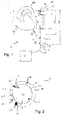
- a lung support system 1 is shown with a perfusion cannula 10, which can be arranged in the area of a heart 30 of a patient, in particular in an aorta 31 near an aortic arch 31a.
- the perfusion cannula 10 is coupled to an evaluation unit 20 via an electrical connection 18 and extends along a central longitudinal axis M. It has a distal end 10a (cannula tip) and a proximal end 10b.
- the perfusion cannula 10 is divided into two sections, a distal insertion section with an insertion length L1, and a proximal section, which are provided together over a total length L2 of the perfusion cannula 10.
- the perfusion cannula 10 has a cannula wall 12 which has a diameter D2 in the region of the proximal end 10b and a diameter D1 in the region of the distal end 10a.
- the diameter D1 is smaller than the diameter D2.
- the perfusion cannula 10 has a sensor lumen 16, indicated by dashed lines, in which an electrical line is routed, via which ring electrodes 17.1, 17.2 are electrically contacted.
- the ring electrodes 17.1, 17.2 are arranged on the outside of the cannula wall 12.
- the distal electrode 17.1 is arranged at a distance x1 from the distal end 10a, the distance x1, for example, in the range of 4 cm and the proximal electrode 17.2 is arranged at a distance x2 from the distal end 10a, so that the electrodes are arranged at a distance x3 of approximately 40 to 60 mm from one another.
- a perfusion cannula 10 is shown with a cannula wall 12, the cannula wall 12 having a cylindrical inner jacket surface 12a and a cylindrical outer jacket surface 12b, and the cylindrical inner jacket surface 12a delimits a perfusion lumen 13.
- the jacket surfaces 12a, 12b are arranged concentrically around a central longitudinal axis M.
- Five sensor lumens 16.1, 16.2, 16.3, 16.4, 16.5, which are arranged concentrically around the central longitudinal axis M, are integrated into the cannula wall 12.
- An EKG sensor 17 is embedded in a first of the sensor lumens 16.1, and a pressure sensor 19 is embedded in a fifth of the sensor lumens 16.5.
- the cannula wall 12 has a wall thickness d which is in the range of 0.75 mm, and the first sensor lumen 16.1 has a diameter d1 which is in the range of 0.25 mm, and the fifth sensor lumen 16.5 has a diameter d5 which is in the range of 0.55 mm.
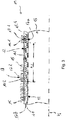
- a perfusion cannula 10 is shown with a cannula wall 12 which delimits a perfusion lumen 13.
- the perfusion cannula 10 extends along a central longitudinal axis M.
- a sensor lumen 16.1 for an EKG sensor 17 is integrated into the cannula wall 12, the EKG sensor 17 being embedded in the sensor lumen 16.1 in an embedding 11 so that a distal end 17a of the EKG sensor 17 is enclosed by the embedding 11.
- the EKG sensor 17 has two ring electrodes 17.1, 17.2 which are arranged around the cannula wall 12 at a distance x3 from one another.
- the ring electrodes 17.1, 17.2 are each connected to an electrical conductor 17b of the EKG sensor 17 via bushings 14.1, 14.2.
- the ring electrodes 17.1, 17.2 cover the bushings 14.1, 14.2.
- a wire reinforcement 15 is provided around the outside of the cannula wall 12, which is provided starting from a proximal end of the perfusion cannula 10 to the proximally arranged (second) ring electrode 17.2 and can optionally also be provided distal from the second ring electrode 17.2 as shown.
- the wire reinforcement 15 is preferably formed from two individual sections.
- a perfusion cannula 10 is shown which, in contrast to the one in FIG Fig. 3
- the perfusion cannula 10 shown does not have ring electrodes, but rather electrodes 17.1, 17.2 of an EKG sensor 17 arranged within a sensor lumen 16.1.
- the EKG sensor 17 is arranged completely in an embedding 11 and (only) sealed off from a distal end 10 a of the perfusion cannula 10.
- the perfusion cannula 10 therefore has no feedthroughs, and a wire reinforcement 15 is made in one piece and wound continuously around a cannula wall 12.
- Fig. 5 shows a perfusion cannula 10 with a perfusion lumen 13 and with a sensor lumen 16.5, in which a pressure sensor 19 is embedded in an embedding 11 within a cannula wall 12, a distal end 19a of the pressure sensor 19 in the distal direction from the embedding 11 in the area of a distal one
- the end 10a of the perfusion cannula 10 protrudes. This enables a pressure measurement to be carried out in a fiber-optic manner.
- the perfusion cannula 10 can, in addition to the sensor lumen 16.5 or the pressure sensor 19, as in FIG Fig. 3 and 4th shown have a sensor lumen or an EKG sensor.
- a perfusion cannula 10 with a cannula wall 12 is shown, the cannula wall 12 having an inner circumferential surface 12a and a cylindrical outer circumferential surface 12b, and the inner circumferential surface 12a delimits a perfusion lumen 13.
- Three lumens 16.1, 16.2, 16.5 are integrated into the cannula wall 12, a first sensor lumen 16.1 with an EKG sensor 17 arranged therein and a fifth sensor lumen 16.5 with a pressure sensor 19 arranged therein as well as with a free working lumen 16.2, in which, if required, an Working probe (not shown) can be arranged.
- the fifth sensor lumen 16.5 By arranging the fifth sensor lumen 16.5 in an inwardly protruding one Part of the cannula wall 12 is a wall thickness d of the cannula wall 12 with respect to a diameter d5 of the fifth sensor lumen 16.5 made comparatively thin, in particular with regard to a good flexibility of the perfusion cannula 10, even if a larger sensor lumen or working lumen should be required.
Claims (15)
- Canule de perfusion (10) destinée à poser un accès et comportant une paroi de canule (12) et une lumière de perfusion (13) délimitée par la paroi de canule (12) et dans laquelle un flux de fluide peut s'écouler à travers la canule de perfusion (10) ; la paroi de canule (12) étant formée avec un côté intérieur au moins approximativement cylindrique d'une surface d'enveloppe intérieure circonférentielle (12a) et un côté extérieur au moins approximativement cylindrique d'une surface d'enveloppe extérieure circonférentielle (12b), les deux surfaces d'enveloppe (12a, 12b) étant disposées concentriquement et
la canule de perfusion (10) comprenant en outre au moins une lumière de capteur (16.1, 16.2, 16.3, 16.4, 16.5) et au moins un dispositif de détection (17, 19) qui est disposé au moins partiellement dans la lumière de capteur (16.1, 16.2, 16.3, 16.4, 16.5),
caractérisée en ce que
l'au moins une lumière de capteur (16.5) est disposée dans une partie faisant saillie vers l'intérieur de la paroi de canule (12), dont l'épaisseur de paroi (d), à part la partie faisant saillie vers l'intérieur de la paroi de canule (12), est comparativement mince par rapport à un diamètre (d5) de la lumière de capteur, et en ce que l'au moins une lumière de capteur (16.5) des lumières de capteur (16.1, 16.2, 16.3, 16.4, 16.5) comprend un capteur de pression (19) en tant que dispositif de détection. - Canule de perfusion (10) selon la revendication 1, caractérisée en ce que la lumière de capteur (16.1, 16.2, 16.3, 16.4, 16.5) est disposée latéralement dans la direction radiale, en faisant saillie vers l'intérieur dans la lumière de perfusion (13) sur la paroi de canule (12).
- Canule de perfusion (10) selon la revendication 1 ou 2, caractérisée en ce que la canule de perfusion (10) a une longueur d'insertion (L1) supérieure à 15 cm, de préférence supérieure à 20 cm, de manière davantage préférée supérieure à 25 cm, en particulier comprise dans une plage allant de 25 à 50 cm.
- Canule de perfusion (10) selon l'une des revendications précédentes, caractérisée en ce que la canule de perfusion (10) présente un diamètre extérieur compris entre 5/3 mm (5 charrière) et 35/3 mm (35 charrière), de préférence entre 4 mm (12 charrière) et 25/3 mm (25 charrière) dans la zone d'une extrémité distale (10a) de la canule de perfusion (10).
- Canule de perfusion (10) selon l'une des revendications précédentes, caractérisée en ce qu'au moins un dispositif de détection (17) disposé au moins partiellement dans une lumière de capteur (16.1) est conçu comme un capteur d'électrocardiogramme et de préférence la lumière de capteur (d'ECG) (16.1) présente un diamètre (d5) compris entre 0,05 et 2 mm, de préférence entre 0,2 et 0,5 mm.
- Canule de perfusion (10) selon l'une des revendications précédentes, caractérisée en ce qu'au moins un de l'au moins un dispositif de détection (17) est conçu comme un capteur d'électrocardiogramme et comporte une électrode annulaire (17.1, 17.2) qui est disposée à l'extérieur autour de la paroi de canule (12) et est mise en contact électrique par un passage (14.1, 14.2) dans la paroi de canule (12) au moyen d'un conducteur électrique (17b) passant dans la lumière de capteur correspondante (16.1).
- Canule de perfusion (10) selon l'une des revendications précédentes, caractérisée en ce qu'au moins un de l'au moins un dispositif de détection (17) est conçu comme un capteur d'électrocardiogramme avec deux électrodes (17.1, 17.2) disposées dans la lumière de capteur (16.1).
- Canule de perfusion (10) selon la revendication 1, caractérisée en ce que le capteur de pression (19) est conçu comme un capteur de pression à fibre optique.
- Canule de perfusion (10) selon la revendication 8, caractérisée en ce que le capteur de pression à fibre optique présente une extrémité distale (19a) qui est disposée à une distance de maximum 5 cm, de préférence de maximum 3 cm, de manière davantage préférée de maximum 1 cm d'une extrémité distale (10a) de la canule de perfusion (10).
- Canule de perfusion (10) selon l'une des revendications précédentes, caractérisée en ce qu'au moins un de l'au moins un dispositif de détection (17, 19) est incorporé de manière étanche dans la lumière de capteur correspondante (16.1, 16.2, 16.3, 16.4, 16.5), en particulier dans la zone d'une extrémité distale (17a, 19a) du dispositif de détection (17, 19).
- Canule de perfusion (10) selon l'une des revendications précédentes, caractérisée en ce que la canule de perfusion (10) présente une armature en fil métallique (15) qui est de préférence disposée radialement à l'extérieur de l'au moins une lumière de capteur (16.1, 16.2, 16.3, 16.4, 16.5).
- Canule de perfusion (10) selon l'une des revendications précédentes, caractérisée en ce que la canule de perfusion (10) est revêtue d'une couche de polyuréthane.
- Canule de perfusion (10) selon l'une des revendications précédentes, caractérisée en ce que la canule de perfusion (10) est constituée de silicone, d'un copolymère de silicone-polyuréthane, de PVC, de polyuréthane et/ou d'acier inoxydable V1.
- Canule de perfusion (10) selon l'une des revendications précédentes, caractérisée en ce que la canule de perfusion (10) présente une lumière de travail libre (16.2, 16.3, 16.4) dans laquelle une sonde de travail peut être disposée.
- Système (1), en particulier système d'assistance circulatoire, comportant une canule de perfusion (10) selon l'une des revendications précédentes pour un accès artériel et une canule de drainage ainsi qu'une unité d'évaluation (20) pour évaluer les valeurs mesurées d'au moins l'un de l'au moins un dispositif de détection (17, 19) de la canule de perfusion (10).
Priority Applications (3)
| Application Number | Priority Date | Filing Date | Title |
|---|---|---|---|
| EP13003716.1A EP2829226B1 (fr) | 2013-07-24 | 2013-07-24 | Canule de perfusion à technique sensorielle intégrée |
| US14/338,213 US9717434B2 (en) | 2013-07-24 | 2014-07-22 | Perfusion cannula with integrated sensor technology |
| JP2014149991A JP6558881B2 (ja) | 2013-07-24 | 2014-07-23 | 一体化されたセンサ技術を有する灌流カニューレ |
Applications Claiming Priority (1)
| Application Number | Priority Date | Filing Date | Title |
|---|---|---|---|
| EP13003716.1A EP2829226B1 (fr) | 2013-07-24 | 2013-07-24 | Canule de perfusion à technique sensorielle intégrée |
Publications (2)
| Publication Number | Publication Date |
|---|---|
| EP2829226A1 EP2829226A1 (fr) | 2015-01-28 |
| EP2829226B1 true EP2829226B1 (fr) | 2021-03-24 |
Family
ID=48874109
Family Applications (1)
| Application Number | Title | Priority Date | Filing Date |
|---|---|---|---|
| EP13003716.1A Active EP2829226B1 (fr) | 2013-07-24 | 2013-07-24 | Canule de perfusion à technique sensorielle intégrée |
Country Status (3)
| Country | Link |
|---|---|
| US (1) | US9717434B2 (fr) |
| EP (1) | EP2829226B1 (fr) |
| JP (1) | JP6558881B2 (fr) |
Families Citing this family (5)
| Publication number | Priority date | Publication date | Assignee | Title |
|---|---|---|---|---|
| EP3541460B1 (fr) * | 2016-11-21 | 2020-12-23 | Cardiac Pacemakers, Inc. | Dispositifs de placement et détection de l'apposition contre une paroi |
| JP7128614B2 (ja) * | 2017-08-30 | 2022-08-31 | マニー株式会社 | インフュージョンパイプ |
| JP7468355B2 (ja) | 2018-11-13 | 2024-04-16 | Agc株式会社 | 撥水撥油層付き基材、蒸着材料および撥水撥油層付き基材の製造方法 |
| CN109805926A (zh) * | 2019-03-19 | 2019-05-28 | 苏州润迈德医疗科技有限公司 | 用于冠脉内心电图的信号测量装置 |
| US11723517B2 (en) * | 2019-12-31 | 2023-08-15 | Biosense Webster (Israel) Ltd. | Wiring of trocar having movable camera and fixed position sensor |
Citations (5)
| Publication number | Priority date | Publication date | Assignee | Title |
|---|---|---|---|---|
| US5425724A (en) * | 1994-04-26 | 1995-06-20 | Akins; Cary W. | Aortic perfusion cannula |
| WO2000057805A1 (fr) * | 1999-03-30 | 2000-10-05 | A-Med Systems, Inc. | Canule sensible a la pression |
| US20100094255A1 (en) * | 2006-07-06 | 2010-04-15 | Warsaw Orthopedic, Inc. | Cannulated sensing device |
| US7787963B2 (en) * | 2006-07-13 | 2010-08-31 | Biotronik Crm Patent Ag | Device for insertion of electrode lines or other medical instruments into a body |
| US20110092955A1 (en) * | 2009-10-07 | 2011-04-21 | Purdy Phillip D | Pressure-Sensing Medical Devices, Systems and Methods, and Methods of Forming Medical Devices |
Family Cites Families (14)
| Publication number | Priority date | Publication date | Assignee | Title |
|---|---|---|---|---|
| AU580733B2 (en) * | 1983-05-25 | 1989-02-02 | Camino Laboratories, Inc. | Fiber-optic transducer apparatus |
| US4692148A (en) * | 1986-03-28 | 1987-09-08 | Aisin Seiki Kabushiki Kaisha | Intra-aortic balloon pump apparatus and method of using same |
| JPS6468236A (en) * | 1987-09-07 | 1989-03-14 | Aisin Seiki | Cannula equipped with detection electrode |
| US5029585A (en) * | 1989-07-14 | 1991-07-09 | Baxter International Inc. | Comformable intralumen electrodes |
| US5065010A (en) * | 1990-08-30 | 1991-11-12 | Camino Laboratories | Fiber optic measurement system having a reference conductor for controlling the energy level of the light source |
| US5171218A (en) * | 1992-01-02 | 1992-12-15 | Trustees Of Boston University | Bidirectional femoral arterial cannula |
| US5433742A (en) * | 1993-11-19 | 1995-07-18 | Willis; Allan | Conductive adhesive band for cathether electrode |
| US5701905A (en) * | 1995-11-13 | 1997-12-30 | Localmed, Inc. | Guide catheter with sensing element |
| US7935108B2 (en) * | 1999-07-14 | 2011-05-03 | Cardiofocus, Inc. | Deflectable sheath catheters |
| AU7354400A (en) * | 1999-09-03 | 2001-04-10 | A-Med Systems, Inc. | Guidable intravascular blood pump and related methods |
| US20020111662A1 (en) * | 2001-02-09 | 2002-08-15 | Iaizzo Paul A. | System and method for placing an implantable medical device within a body |
| JP4220339B2 (ja) * | 2003-09-11 | 2009-02-04 | 日本ライフライン株式会社 | カテーテル |
| JP5347656B2 (ja) * | 2009-03-31 | 2013-11-20 | 日本ゼオン株式会社 | カテーテル |
| US8267887B2 (en) * | 2010-05-26 | 2012-09-18 | Miracor Medical Systems Gmbh | Treating heart tissue |
-
2013
- 2013-07-24 EP EP13003716.1A patent/EP2829226B1/fr active Active
-
2014
- 2014-07-22 US US14/338,213 patent/US9717434B2/en active Active
- 2014-07-23 JP JP2014149991A patent/JP6558881B2/ja active Active
Patent Citations (5)
| Publication number | Priority date | Publication date | Assignee | Title |
|---|---|---|---|---|
| US5425724A (en) * | 1994-04-26 | 1995-06-20 | Akins; Cary W. | Aortic perfusion cannula |
| WO2000057805A1 (fr) * | 1999-03-30 | 2000-10-05 | A-Med Systems, Inc. | Canule sensible a la pression |
| US20100094255A1 (en) * | 2006-07-06 | 2010-04-15 | Warsaw Orthopedic, Inc. | Cannulated sensing device |
| US7787963B2 (en) * | 2006-07-13 | 2010-08-31 | Biotronik Crm Patent Ag | Device for insertion of electrode lines or other medical instruments into a body |
| US20110092955A1 (en) * | 2009-10-07 | 2011-04-21 | Purdy Phillip D | Pressure-Sensing Medical Devices, Systems and Methods, and Methods of Forming Medical Devices |
Also Published As
| Publication number | Publication date |
|---|---|
| EP2829226A1 (fr) | 2015-01-28 |
| JP6558881B2 (ja) | 2019-08-14 |
| US20150031977A1 (en) | 2015-01-29 |
| US9717434B2 (en) | 2017-08-01 |
| JP2015037541A (ja) | 2015-02-26 |
Similar Documents
| Publication | Publication Date | Title |
|---|---|---|
| DE19734220C2 (de) | Kathetersystem mit einem Einführungsdraht | |
| EP1876948B1 (fr) | Dispositif permettant l'acquisition de grandeurs de mesure physiologiques a l'interieur d'un corps | |
| DE69629418T2 (de) | Koronarsinus Katheter | |
| DE60220417T2 (de) | Katheterführung in flussrichtung mit schaft variabler steifheit | |
| DE602004008425T2 (de) | System für den Zugang zum Koronarsinus zur Erleichterung der Einführung von Schrittmacherleitungen | |
| DE60212048T2 (de) | Katheter mit verbesserter distaler Schubfähigkeit | |
| DE60313805T2 (de) | Steuerbarer Katheter | |
| DE69724605T2 (de) | Katheter mit einer kurve mit ansteigendem radius | |
| EP2829226B1 (fr) | Canule de perfusion à technique sensorielle intégrée | |
| DE69938002T2 (de) | Vorrichtung zum intravaskularen anbringen einer kanüle sowie anwendungsverfahren | |
| DE60211896T2 (de) | Verformbare langgestreckte medizinische vorrichtung | |
| EP3328478B1 (fr) | Système de ponction | |
| DE60015742T2 (de) | Medizinische elektrodenleitung | |
| DE202014100938U1 (de) | Druckmessvorrichtung | |
| DE10261575A1 (de) | Vorrichtung zur Kanülierung eines Blut führenden Gefäßes und deren Verwendung zur Kanülierung von Blut führenden Gefäßen | |
| DE3704500A1 (de) | Diagnosekatheter zur ueberwachung des herzausstosses | |
| WO2011039091A1 (fr) | Système d'assistance cardiaque | |
| EP1402917B1 (fr) | Cathéter avec fibre optique | |
| DE60015367T2 (de) | Intraaortaler ballonkatheter mit einem konisch zulaufenden, y-verbindungsstück | |
| EP3090766B1 (fr) | Dispositif de réglage des paramètres vitaux du système cardiovasculaire | |
| DE102010053789A1 (de) | Vorrichtung zur Durchführung physiologischer Messungen | |
| DE112021006371T5 (de) | Systeme und verfahren zur bestimmung der positionierung von intrakardialen vorrichtungen | |
| DE102018104168B3 (de) | Aortenkanüle mit Absaugkatheter | |
| DE112020004693T5 (de) | Verformbarer hülsenkörper | |
| DE3417479A1 (de) | Venenkatheter mit fuehrungsmandrin zur ekg-abnahme |
Legal Events
| Date | Code | Title | Description |
|---|---|---|---|
| 17P | Request for examination filed |
Effective date: 20130724 |
|
| AK | Designated contracting states |
Kind code of ref document: A1 Designated state(s): AL AT BE BG CH CY CZ DE DK EE ES FI FR GB GR HR HU IE IS IT LI LT LU LV MC MK MT NL NO PL PT RO RS SE SI SK SM TR |
|
| AX | Request for extension of the european patent |
Extension state: BA ME |
|
| PUAI | Public reference made under article 153(3) epc to a published international application that has entered the european phase |
Free format text: ORIGINAL CODE: 0009012 |
|
| R17P | Request for examination filed (corrected) |
Effective date: 20150728 |
|
| RBV | Designated contracting states (corrected) |
Designated state(s): AL AT BE BG CH CY CZ DE DK EE ES FI FR GB GR HR HU IE IS IT LI LT LU LV MC MK MT NL NO PL PT RO RS SE SI SK SM TR |
|
| STAA | Information on the status of an ep patent application or granted ep patent |
Free format text: STATUS: EXAMINATION IS IN PROGRESS |
|
| 17Q | First examination report despatched |
Effective date: 20170619 |
|
| GRAP | Despatch of communication of intention to grant a patent |
Free format text: ORIGINAL CODE: EPIDOSNIGR1 |
|
| STAA | Information on the status of an ep patent application or granted ep patent |
Free format text: STATUS: GRANT OF PATENT IS INTENDED |
|
| INTG | Intention to grant announced |
Effective date: 20201023 |
|
| GRAS | Grant fee paid |
Free format text: ORIGINAL CODE: EPIDOSNIGR3 |
|
| GRAA | (expected) grant |
Free format text: ORIGINAL CODE: 0009210 |
|
| STAA | Information on the status of an ep patent application or granted ep patent |
Free format text: STATUS: THE PATENT HAS BEEN GRANTED |
|
| AK | Designated contracting states |
Kind code of ref document: B1 Designated state(s): AL AT BE BG CH CY CZ DE DK EE ES FI FR GB GR HR HU IE IS IT LI LT LU LV MC MK MT NL NO PL PT RO RS SE SI SK SM TR |
|
| REG | Reference to a national code |
Ref country code: GB Ref legal event code: FG4D Free format text: NOT ENGLISH |
|
| REG | Reference to a national code |
Ref country code: CH Ref legal event code: EP |
|
| REG | Reference to a national code |
Ref country code: DE Ref legal event code: R096 Ref document number: 502013015581 Country of ref document: DE |
|
| REG | Reference to a national code |
Ref country code: IE Ref legal event code: FG4D Free format text: LANGUAGE OF EP DOCUMENT: GERMAN |
|
| REG | Reference to a national code |
Ref country code: AT Ref legal event code: REF Ref document number: 1373641 Country of ref document: AT Kind code of ref document: T Effective date: 20210415 |
|
| REG | Reference to a national code |
Ref country code: SE Ref legal event code: TRGR |
|
| REG | Reference to a national code |
Ref country code: LT Ref legal event code: MG9D |
|
| PG25 | Lapsed in a contracting state [announced via postgrant information from national office to epo] |
Ref country code: HR Free format text: LAPSE BECAUSE OF FAILURE TO SUBMIT A TRANSLATION OF THE DESCRIPTION OR TO PAY THE FEE WITHIN THE PRESCRIBED TIME-LIMIT Effective date: 20210324 Ref country code: FI Free format text: LAPSE BECAUSE OF FAILURE TO SUBMIT A TRANSLATION OF THE DESCRIPTION OR TO PAY THE FEE WITHIN THE PRESCRIBED TIME-LIMIT Effective date: 20210324 Ref country code: GR Free format text: LAPSE BECAUSE OF FAILURE TO SUBMIT A TRANSLATION OF THE DESCRIPTION OR TO PAY THE FEE WITHIN THE PRESCRIBED TIME-LIMIT Effective date: 20210625 Ref country code: NO Free format text: LAPSE BECAUSE OF FAILURE TO SUBMIT A TRANSLATION OF THE DESCRIPTION OR TO PAY THE FEE WITHIN THE PRESCRIBED TIME-LIMIT Effective date: 20210624 Ref country code: BG Free format text: LAPSE BECAUSE OF FAILURE TO SUBMIT A TRANSLATION OF THE DESCRIPTION OR TO PAY THE FEE WITHIN THE PRESCRIBED TIME-LIMIT Effective date: 20210624 |
|
| PG25 | Lapsed in a contracting state [announced via postgrant information from national office to epo] |
Ref country code: RS Free format text: LAPSE BECAUSE OF FAILURE TO SUBMIT A TRANSLATION OF THE DESCRIPTION OR TO PAY THE FEE WITHIN THE PRESCRIBED TIME-LIMIT Effective date: 20210324 Ref country code: LV Free format text: LAPSE BECAUSE OF FAILURE TO SUBMIT A TRANSLATION OF THE DESCRIPTION OR TO PAY THE FEE WITHIN THE PRESCRIBED TIME-LIMIT Effective date: 20210324 |
|
| REG | Reference to a national code |
Ref country code: NL Ref legal event code: MP Effective date: 20210324 |
|
| PG25 | Lapsed in a contracting state [announced via postgrant information from national office to epo] |
Ref country code: NL Free format text: LAPSE BECAUSE OF FAILURE TO SUBMIT A TRANSLATION OF THE DESCRIPTION OR TO PAY THE FEE WITHIN THE PRESCRIBED TIME-LIMIT Effective date: 20210324 |
|
| PG25 | Lapsed in a contracting state [announced via postgrant information from national office to epo] |
Ref country code: LT Free format text: LAPSE BECAUSE OF FAILURE TO SUBMIT A TRANSLATION OF THE DESCRIPTION OR TO PAY THE FEE WITHIN THE PRESCRIBED TIME-LIMIT Effective date: 20210324 Ref country code: CZ Free format text: LAPSE BECAUSE OF FAILURE TO SUBMIT A TRANSLATION OF THE DESCRIPTION OR TO PAY THE FEE WITHIN THE PRESCRIBED TIME-LIMIT Effective date: 20210324 Ref country code: EE Free format text: LAPSE BECAUSE OF FAILURE TO SUBMIT A TRANSLATION OF THE DESCRIPTION OR TO PAY THE FEE WITHIN THE PRESCRIBED TIME-LIMIT Effective date: 20210324 Ref country code: SM Free format text: LAPSE BECAUSE OF FAILURE TO SUBMIT A TRANSLATION OF THE DESCRIPTION OR TO PAY THE FEE WITHIN THE PRESCRIBED TIME-LIMIT Effective date: 20210324 |
|
| PG25 | Lapsed in a contracting state [announced via postgrant information from national office to epo] |
Ref country code: IS Free format text: LAPSE BECAUSE OF FAILURE TO SUBMIT A TRANSLATION OF THE DESCRIPTION OR TO PAY THE FEE WITHIN THE PRESCRIBED TIME-LIMIT Effective date: 20210724 Ref country code: RO Free format text: LAPSE BECAUSE OF FAILURE TO SUBMIT A TRANSLATION OF THE DESCRIPTION OR TO PAY THE FEE WITHIN THE PRESCRIBED TIME-LIMIT Effective date: 20210324 Ref country code: PL Free format text: LAPSE BECAUSE OF FAILURE TO SUBMIT A TRANSLATION OF THE DESCRIPTION OR TO PAY THE FEE WITHIN THE PRESCRIBED TIME-LIMIT Effective date: 20210324 Ref country code: PT Free format text: LAPSE BECAUSE OF FAILURE TO SUBMIT A TRANSLATION OF THE DESCRIPTION OR TO PAY THE FEE WITHIN THE PRESCRIBED TIME-LIMIT Effective date: 20210726 Ref country code: ES Free format text: LAPSE BECAUSE OF FAILURE TO SUBMIT A TRANSLATION OF THE DESCRIPTION OR TO PAY THE FEE WITHIN THE PRESCRIBED TIME-LIMIT Effective date: 20210324 Ref country code: SK Free format text: LAPSE BECAUSE OF FAILURE TO SUBMIT A TRANSLATION OF THE DESCRIPTION OR TO PAY THE FEE WITHIN THE PRESCRIBED TIME-LIMIT Effective date: 20210324 |
|
| REG | Reference to a national code |
Ref country code: DE Ref legal event code: R097 Ref document number: 502013015581 Country of ref document: DE |
|
| PG25 | Lapsed in a contracting state [announced via postgrant information from national office to epo] |
Ref country code: AL Free format text: LAPSE BECAUSE OF FAILURE TO SUBMIT A TRANSLATION OF THE DESCRIPTION OR TO PAY THE FEE WITHIN THE PRESCRIBED TIME-LIMIT Effective date: 20210324 Ref country code: DK Free format text: LAPSE BECAUSE OF FAILURE TO SUBMIT A TRANSLATION OF THE DESCRIPTION OR TO PAY THE FEE WITHIN THE PRESCRIBED TIME-LIMIT Effective date: 20210324 |
|
| PLBE | No opposition filed within time limit |
Free format text: ORIGINAL CODE: 0009261 |
|
| STAA | Information on the status of an ep patent application or granted ep patent |
Free format text: STATUS: NO OPPOSITION FILED WITHIN TIME LIMIT |
|
| PG25 | Lapsed in a contracting state [announced via postgrant information from national office to epo] |
Ref country code: SI Free format text: LAPSE BECAUSE OF FAILURE TO SUBMIT A TRANSLATION OF THE DESCRIPTION OR TO PAY THE FEE WITHIN THE PRESCRIBED TIME-LIMIT Effective date: 20210324 |
|
| REG | Reference to a national code |
Ref country code: CH Ref legal event code: PL |
|
| 26N | No opposition filed |
Effective date: 20220104 |
|
| PG25 | Lapsed in a contracting state [announced via postgrant information from national office to epo] |
Ref country code: MC Free format text: LAPSE BECAUSE OF FAILURE TO SUBMIT A TRANSLATION OF THE DESCRIPTION OR TO PAY THE FEE WITHIN THE PRESCRIBED TIME-LIMIT Effective date: 20210324 |
|
| REG | Reference to a national code |
Ref country code: BE Ref legal event code: MM Effective date: 20210731 |
|
| PG25 | Lapsed in a contracting state [announced via postgrant information from national office to epo] |
Ref country code: LI Free format text: LAPSE BECAUSE OF NON-PAYMENT OF DUE FEES Effective date: 20210731 Ref country code: CH Free format text: LAPSE BECAUSE OF NON-PAYMENT OF DUE FEES Effective date: 20210731 |
|
| PG25 | Lapsed in a contracting state [announced via postgrant information from national office to epo] |
Ref country code: IS Free format text: LAPSE BECAUSE OF FAILURE TO SUBMIT A TRANSLATION OF THE DESCRIPTION OR TO PAY THE FEE WITHIN THE PRESCRIBED TIME-LIMIT Effective date: 20210724 Ref country code: LU Free format text: LAPSE BECAUSE OF NON-PAYMENT OF DUE FEES Effective date: 20210724 |
|
| PG25 | Lapsed in a contracting state [announced via postgrant information from national office to epo] |
Ref country code: IE Free format text: LAPSE BECAUSE OF NON-PAYMENT OF DUE FEES Effective date: 20210724 Ref country code: BE Free format text: LAPSE BECAUSE OF NON-PAYMENT OF DUE FEES Effective date: 20210731 |
|
| REG | Reference to a national code |
Ref country code: AT Ref legal event code: MM01 Ref document number: 1373641 Country of ref document: AT Kind code of ref document: T Effective date: 20210724 |
|
| PG25 | Lapsed in a contracting state [announced via postgrant information from national office to epo] |
Ref country code: AT Free format text: LAPSE BECAUSE OF NON-PAYMENT OF DUE FEES Effective date: 20210724 |
|
| PG25 | Lapsed in a contracting state [announced via postgrant information from national office to epo] |
Ref country code: HU Free format text: LAPSE BECAUSE OF FAILURE TO SUBMIT A TRANSLATION OF THE DESCRIPTION OR TO PAY THE FEE WITHIN THE PRESCRIBED TIME-LIMIT; INVALID AB INITIO Effective date: 20130724 |
|
| PG25 | Lapsed in a contracting state [announced via postgrant information from national office to epo] |
Ref country code: CY Free format text: LAPSE BECAUSE OF FAILURE TO SUBMIT A TRANSLATION OF THE DESCRIPTION OR TO PAY THE FEE WITHIN THE PRESCRIBED TIME-LIMIT Effective date: 20210324 |
|
| P01 | Opt-out of the competence of the unified patent court (upc) registered |
Effective date: 20230602 |
|
| PGFP | Annual fee paid to national office [announced via postgrant information from national office to epo] |
Ref country code: IT Payment date: 20230620 Year of fee payment: 11 Ref country code: FR Payment date: 20230621 Year of fee payment: 11 |
|
| PGFP | Annual fee paid to national office [announced via postgrant information from national office to epo] |
Ref country code: SE Payment date: 20230622 Year of fee payment: 11 |
|
| PGFP | Annual fee paid to national office [announced via postgrant information from national office to epo] |
Ref country code: GB Payment date: 20230620 Year of fee payment: 11 |
|
| PGFP | Annual fee paid to national office [announced via postgrant information from national office to epo] |
Ref country code: DE Payment date: 20230620 Year of fee payment: 11 |