EP2829226B1 - Perfusion cannula with integrated sensors - Google Patents
Perfusion cannula with integrated sensors Download PDFInfo
- Publication number
- EP2829226B1 EP2829226B1 EP13003716.1A EP13003716A EP2829226B1 EP 2829226 B1 EP2829226 B1 EP 2829226B1 EP 13003716 A EP13003716 A EP 13003716A EP 2829226 B1 EP2829226 B1 EP 2829226B1
- Authority
- EP
- European Patent Office
- Prior art keywords
- cannula
- sensor
- perfusion
- perfusion cannula
- lumen
- Prior art date
- Legal status (The legal status is an assumption and is not a legal conclusion. Google has not performed a legal analysis and makes no representation as to the accuracy of the status listed.)
- Active
Links
Images


Classifications
-
- A—HUMAN NECESSITIES
- A61—MEDICAL OR VETERINARY SCIENCE; HYGIENE
- A61B—DIAGNOSIS; SURGERY; IDENTIFICATION
- A61B5/00—Measuring for diagnostic purposes; Identification of persons
- A61B5/68—Arrangements of detecting, measuring or recording means, e.g. sensors, in relation to patient
- A61B5/6846—Arrangements of detecting, measuring or recording means, e.g. sensors, in relation to patient specially adapted to be brought in contact with an internal body part, i.e. invasive
- A61B5/6847—Arrangements of detecting, measuring or recording means, e.g. sensors, in relation to patient specially adapted to be brought in contact with an internal body part, i.e. invasive mounted on an invasive device
- A61B5/6866—Extracorporeal blood circuits, e.g. dialysis circuits
-
- A—HUMAN NECESSITIES
- A61—MEDICAL OR VETERINARY SCIENCE; HYGIENE
- A61B—DIAGNOSIS; SURGERY; IDENTIFICATION
- A61B5/00—Measuring for diagnostic purposes; Identification of persons
- A61B5/24—Detecting, measuring or recording bioelectric or biomagnetic signals of the body or parts thereof
- A61B5/25—Bioelectric electrodes therefor
- A61B5/279—Bioelectric electrodes therefor specially adapted for particular uses
- A61B5/28—Bioelectric electrodes therefor specially adapted for particular uses for electrocardiography [ECG]
- A61B5/283—Invasive
- A61B5/29—Invasive for permanent or long-term implantation
-
- A—HUMAN NECESSITIES
- A61—MEDICAL OR VETERINARY SCIENCE; HYGIENE
- A61B—DIAGNOSIS; SURGERY; IDENTIFICATION
- A61B5/00—Measuring for diagnostic purposes; Identification of persons
- A61B5/02—Detecting, measuring or recording for evaluating the cardiovascular system, e.g. pulse, heart rate, blood pressure or blood flow
- A61B5/021—Measuring pressure in heart or blood vessels
- A61B5/0215—Measuring pressure in heart or blood vessels by means inserted into the body
- A61B5/02154—Measuring pressure in heart or blood vessels by means inserted into the body by optical transmission
-
- A—HUMAN NECESSITIES
- A61—MEDICAL OR VETERINARY SCIENCE; HYGIENE
- A61B—DIAGNOSIS; SURGERY; IDENTIFICATION
- A61B5/00—Measuring for diagnostic purposes; Identification of persons
- A61B5/24—Detecting, measuring or recording bioelectric or biomagnetic signals of the body or parts thereof
- A61B5/25—Bioelectric electrodes therefor
- A61B5/279—Bioelectric electrodes therefor specially adapted for particular uses
- A61B5/28—Bioelectric electrodes therefor specially adapted for particular uses for electrocardiography [ECG]
- A61B5/283—Invasive
- A61B5/287—Holders for multiple electrodes, e.g. electrode catheters for electrophysiological study [EPS]
-
- A—HUMAN NECESSITIES
- A61—MEDICAL OR VETERINARY SCIENCE; HYGIENE
- A61M—DEVICES FOR INTRODUCING MEDIA INTO, OR ONTO, THE BODY; DEVICES FOR TRANSDUCING BODY MEDIA OR FOR TAKING MEDIA FROM THE BODY; DEVICES FOR PRODUCING OR ENDING SLEEP OR STUPOR
- A61M1/00—Suction or pumping devices for medical purposes; Devices for carrying-off, for treatment of, or for carrying-over, body-liquids; Drainage systems
- A61M1/36—Other treatment of blood in a by-pass of the natural circulatory system, e.g. temperature adaptation, irradiation ; Extra-corporeal blood circuits
- A61M1/3621—Extra-corporeal blood circuits
- A61M1/3653—Interfaces between patient blood circulation and extra-corporal blood circuit
- A61M1/3659—Cannulae pertaining to extracorporeal circulation
-
- A—HUMAN NECESSITIES
- A61—MEDICAL OR VETERINARY SCIENCE; HYGIENE
- A61B—DIAGNOSIS; SURGERY; IDENTIFICATION
- A61B2562/00—Details of sensors; Constructional details of sensor housings or probes; Accessories for sensors
- A61B2562/22—Arrangements of medical sensors with cables or leads; Connectors or couplings specifically adapted for medical sensors
- A61B2562/221—Arrangements of sensors with cables or leads, e.g. cable harnesses
- A61B2562/223—Optical cables therefor
-
- A—HUMAN NECESSITIES
- A61—MEDICAL OR VETERINARY SCIENCE; HYGIENE
- A61M—DEVICES FOR INTRODUCING MEDIA INTO, OR ONTO, THE BODY; DEVICES FOR TRANSDUCING BODY MEDIA OR FOR TAKING MEDIA FROM THE BODY; DEVICES FOR PRODUCING OR ENDING SLEEP OR STUPOR
- A61M25/00—Catheters; Hollow probes
- A61M2025/0001—Catheters; Hollow probes for pressure measurement
- A61M2025/0002—Catheters; Hollow probes for pressure measurement with a pressure sensor at the distal end
-
- A—HUMAN NECESSITIES
- A61—MEDICAL OR VETERINARY SCIENCE; HYGIENE
- A61M—DEVICES FOR INTRODUCING MEDIA INTO, OR ONTO, THE BODY; DEVICES FOR TRANSDUCING BODY MEDIA OR FOR TAKING MEDIA FROM THE BODY; DEVICES FOR PRODUCING OR ENDING SLEEP OR STUPOR
- A61M2205/00—General characteristics of the apparatus
- A61M2205/33—Controlling, regulating or measuring
- A61M2205/3331—Pressure; Flow
- A61M2205/3344—Measuring or controlling pressure at the body treatment site
-
- A—HUMAN NECESSITIES
- A61—MEDICAL OR VETERINARY SCIENCE; HYGIENE
- A61M—DEVICES FOR INTRODUCING MEDIA INTO, OR ONTO, THE BODY; DEVICES FOR TRANSDUCING BODY MEDIA OR FOR TAKING MEDIA FROM THE BODY; DEVICES FOR PRODUCING OR ENDING SLEEP OR STUPOR
- A61M2230/00—Measuring parameters of the user
- A61M2230/04—Heartbeat characteristics, e.g. ECG, blood pressure modulation
Definitions
- the invention relates to a perfusion cannula according to the preamble of claim 1 for laying an arterial or venous access, in particular in connection with a circulatory replacement therapy.
- Circulatory replacement therapy can take place, for example, by means of an extracorporeal lung support system, by means of which blood or a fluid replacing the blood is taken from a patient at one point (especially venous) and fed back to another point (especially arterial) after it has been enriched with oxygen and / or the level of carbon dioxide therein has been reduced.
- So-called membrane fans which are also referred to as membrane oxygenators, can be used for this purpose.
- the blood / fluid can be withdrawn or supplied by means of cannulas.
- perfusion refers to the supply of organs with blood. Organ perfusion occurs naturally via arteries and veins, but can also take place artificially, e.g. via bypasses or extracorporeal lines that can be connected to the organism by means of perfusion cannulas. Perfusion cannulas are often used for arterial puncture, but also as venous perfusion cannulas. They provide a supply channel through which a fluid (e.g. blood or a blood substitute) can be supplied or removed. Perfusion cannulas are used, for example, in shock situations in humans or animals. In shock situations, monitoring of the vital status is also of great importance.
- a fluid e.g. blood or a blood substitute
- an electrocardiogram can be created, i.e. a cardiac voltage curve.
- the electrocardiogram is usually recorded via an impedance measurement by means of (adhesive) electrodes attached to the skin of the person / animal (hereinafter “patient”).
- An EKG measurement is made more difficult, for example, by high skin resistance or by adhesive electrodes that do not adhere adequately to the skin (especially due to damp skin). There is also the risk that the skin will be injured by the electrodes.
- the measurement is also made more difficult by the fact that the electrodes can slip, which can be a major problem in the event of resistance or unstable positioning of a patient.
- Blood pressure can be measured in an invasive manner, for example, by using a cannula to record a pressure in one of the patient's peripheral arteries, e.g. an artery in the arm or leg.
- a pressure measurement requires a separate pressure measurement system in which the pressure is recorded via a water column to a pressure measurement system and is fed to a monitoring system for checking vital functions or for diagnosing the patient.
- peripheral vasoconstriction vaconstriction
- the cannulation required for this pressure measurement can usually only be placed with difficulty because the preferred places on the wrists and elbows are severely narrowed, or because inguinal vessels are occupied by extracorporeal procedures.
- U.S. 5,029,585 A discloses electrodes for use with medical catheters.
- the catheter has a cannula wall and a perfusion volume delimited by the cannula wall.
- a sensor lumen is provided.
- U.S. 5,433,742 A describes cardiac catheters that can have adhesive tape electrodes.
- US 2002/111662 A1 describes an implantable medical device that is expandable and may include a pressure sensor. An EKG sensor can be provided.
- US 2011/092955 A1 discloses a perfusion cannula with a cannula wall defining a perfusion lumen.
- a sensor lumen and a sensor device can be provided.
- the document US 2010/0094255 A1 describes a cannulated sensor device having a proximal and a distal end.
- WO 00/57805 A1 describes a cannula with a pressure sensor for measuring the fluid pressure.
- the perfusion cannula should preferably enable safe handling and / or be able to perform functions in a particularly reliable manner. More preferably, the device should also be robust with regard to interfering influences.
- At least one of the aforementioned objects is achieved by a perfusion cannula according to claim 1.
- the invention is based on a perfusion cannula for laying an access with a cannula wall and a perfusion lumen delimited by the cannula wall, in which a fluid stream can flow through the perfusion cannula.
- the perfusion cannula further comprises at least one sensor lumen and at least one sensor device which is at least partially arranged in the sensor lumen.
- vital parameters can also be recorded by means of the sensor device, in particular (blood) pressure and / or a cardiac tension curve, with the vital parameters being able to be recorded within the patient's body, in particular in the immediate vicinity of the heart.
- the vital parameters can thus be reliably recorded even when the patient is in a shock situation in which a narrowing (vasoconstriction) of peripheral, distal vessels of the patient occurs.
- the perfusion cannula can be used, for example, to provide veno-arterial circulatory support, or triggered diastolic augmentation (increase in blood pressure), or, in general, therapy in any kind of shock situation (especially cardiogenic, spetic, traumatic), or resuscitation. Vital functions can be monitored simultaneously.
- the sensor device is preferably positioned in a stationary manner in relation to a (free) distal end of the perfusion cannula in the sensor lumen. As a result, the position of the sensor device relative to the patient is then predetermined by the position of the perfusion cannula, in particular the distal end thereof.
- the sensor device is particularly preferably cast into the cannula wall or embedded therein.
- a perfusion cannula is preferably to be understood as a device which is designed to provide a vascular or organ access for an extracorporeal circuit and through which a fluid can be supplied or removed.
- the access can be an arterial or venous access, preferably a femoral arterial access is made with the perfusion cannula in a groin area of the patient.
- a distal end is preferably to be understood as an end of the perfusion cannula which points away from a surgeon and points to the patient, that is to say the end which has to be introduced into the patient.
- the cannula geometry is preferably designed in such a way that the smallest possible transitions are present at the cannula tip. Transitions smaller than 0.1 mm are preferred.
- the sensor lumen can optionally be designed as a recess, opening, recess or bore extending in a longitudinal direction of the perfusion cannula or it can also be sealed off in the area of a distal end of the perfusion cannula, in particular after a corresponding sensor device has been arranged in a suitable position in the sensor lumen.
- the partition itself can also fix and store the sensor device in the sensor lumen.
- the sensor lumen is preferably designed to be circular in cross section. As a result, a sensor device can be guided through the sensor lumen in a simple manner without colliding with edges or undercuts.
- the sensor lumen is optionally elliptical or round Inner jacket surface with continuous transitions, in particular in accordance with a cross-sectional geometry of a corresponding sensor device.
- One or more sensor lumens can be produced together with the cannula wall by means of a dipping and rotating process. This can be done by applying polymer in layers, comparable to dipping candles, or by means of a metering device on a rotating workpiece carrier. For example, a reinforcement wire, a cable or other components can be incorporated.
- the sensor lumen is formed by a cavity made in the cannula wall in accordance with a placeholder during the manufacturing process (e.g. extrusion).
- a sensor lumen can be provided at a freely selectable position in the cannula wall, and the number of sensor lumens can be freely selected as required, in particular also after the cannula wall of the perfusion cannula has already been produced.
- a sensor lumen can be produced in connection with extrusion, or with a placeholder that is removed after production, or by incorporating prefabricated hollow bodies.
- At least one sensor lumen is integrated into the cannula wall or is arranged on the cannula wall protruding laterally in the radial direction, in particular protruding inward into the perfusion lumen.
- An integrated sensor lumen can ensure that the function of the perfusion cannula for removing or supplying the fluid is not impaired.
- a sensor lumen protruding inward into the perfusion lumen can ensure that sensor devices which are larger in diameter than the wall thickness of the cannula wall can also be used in connection with the persfusion cannula.
- An arrangement laterally on the inside of the cannula has the advantage of being easy to manufacture or also of good flow properties, in particular since the Cannula wall can be made thinner and thus higher flow rates can be achieved with a certain cannula outer diameter.
- a sensor lumen integrated into the cannula wall is to be understood as a lumen which is provided within the cannula wall without the cannula wall being given a special geometry deviating from the actual cannula wall geometry. If the cannula wall is designed as a hollow cylindrical body, for example, the sensor lumen is provided between the two cylindrical outer surfaces without having to deviate from the cylindrical geometry. A sensor lumen integrated into the cannula wall thus has a diameter which is smaller than the thickness of the cannula wall.
- the cannula wall is formed with an at least approximately cylindrical inner side of a circumferential inner jacket surface. Furthermore, the cannula wall is designed with an at least approximately cylindrical outer side of a circumferential outer jacket surface. Since both lateral surfaces are arranged concentrically, this provides direction-independent bending properties and rigidity of the perfusion cannula. With this cross-sectional geometry, the diameter of the perfusion cannula can also be designed to be variable in a simple manner along the longitudinal extent of the perfusion cannula, in particular in the case of a tapering perfusion cannula.
- the perfusion cannula has an insertion length of more than 15 cm, preferably more than 20 cm, more preferably more than 25 cm, in particular in the range from 25 to 50 cm.
- an arterial perfusion cannula can be provided which can also be introduced into a groin area of a patient, and the distal end of which can reach the vicinity of the patient's heart.
- the insertion length is to be understood as the length of the section of the perfusion cannula which can maximally be inserted into a patient.
- the insertion length is preferably significantly greater than 25 cm and is, for example, in the range from 45 to 50 cm.
- the perfusion cannula preferably has a coating with good sliding properties on tissue surfaces.
- the coating can be a polyurethane coating.
- the perfusion cannula preferably has a total length in the range from 20 to 100, more preferably 25 to 75 cm.
- the total length is to be understood as the length of the perfusion cannula from a distal end (cannula tip) to a proximal end, wherein the perfusion cannula can be coupled to a console, in particular an evaluation unit, at the proximal end.
- the total length is greater than the insertion length, so that a surgeon can handle the perfusion cannula in any case, even if it is inserted over the maximum insertion length.
- the total length is preferably at least 10 cm, preferably at least 15 cm, greater than the insertion length.
- the perfusion cannula is preferably designed as an arterial perfusion cannula for introduction into an artery.
- Such an arterial perfusion cannula preferably has no radial recesses or holes in the cannula wall, but only an opening at the distal end through which blood or another fluid can be supplied to a patient.
- Radial recesses or holes in the cannula wall can, however, be provided in venous perfusion cannulas, in particular in order to be able to withdraw a larger amount of blood or fluid from a patient per unit of time (increase of the drainage capacity), in particular to be able to provide a relief effect for the heart.
- ten radial recesses or holes can be provided, in particular in a distal area of the perfusion cannula, in order to be able to withdraw blood / fluid directly from the heart, in particular directly from the atrium of the heart or the superior vena cava (superior vena cava).
- the arterial perfusion cannula also has one or two small radial holes or recesses, but significantly fewer or smaller holes than a venous perfusion cannula.
- the holes preferably have a diameter of 0.5-5 mm, more preferably 1-3 mm.
- the perfusion cannula in the area of a distal end of the perfusion cannula has an outer diameter between 5 and 35 French (Fr) corresponding to about 1.7 and 11.7 mm, preferably between 12 and 25 French (Fr) corresponding to about 4 and 8, 4 mm.
- Fr French
- the patient is not more stressed by means of the perfusion cannula according to the invention than with a conventional cannula, in particular because an incision for introducing the perfusion cannula can remain small despite the additional sensor device (s).
- the area of a distal end is to be understood as a section of the perfusion cannula which extends over a length of at most 5 cm, preferably at most 3 cm, from a distal end of the perfusion cannula in the proximal direction.
- the wall thickness of the perfusion cannula along the entire insertion length is preferably less than 2 mm, preferably less than 1 mm, more preferably less than 0.5 mm. This makes it possible to provide a perfusion cannula, in particular an arterial perfusion cannula, which, despite a considerable length, is flexible and easy to handle and can be advanced from a groin area to the heart of a patient.
- the perfusion cannula preferably has an outer diameter between 5 and 35 French, preferably between 12 and 25 French, in the region of a proximal end of the perfusion cannula. This makes it possible to provide a proximal end which is stable so that a cannula tip can also be pushed through an artery or vein over a greater insertion length.
- the perfusion cannula preferably tapers in the insertion section, in particular continuously over the insertion length.
- the taper is preferably in a connector area the perfusion cannula provided or particularly pronounced.
- the outer diameter is preferably constant in the region of the insertion length.
- a taper is preferably present at the cannula tip.
- At least one of the at least one sensor device is designed as an EKG sensor.
- the (EKG) sensor lumen can have a diameter between 0.05 and 2 mm, preferably 0.2 and 0.5 mm.
- the EKG sensor can essentially be formed by two electrodes and lines that make electrical contact with the electrodes. This allows an EKG measurement to take place using a particularly small sensor that can be guided in the sensor lumen.
- An inner diameter of the sensor lumen which is matched to the outer diameter of the EKG sensor, facilitates the installation of the EKG sensor in the perfusion cannula. For example, it can be prevented that the ECG sensor tilts in the sensor lumen.
- a thin cannula wall with good flexibility (with good elastic properties) can be provided, which has good stability despite the sensor lumen. With a small wall thickness, there is only a slight loss of pressure.
- Such a perfusion cannula with an EKG sensor can be provided for an arterial EKG measurement, that is to say an EKG measurement in which the perfusion cannula is introduced through an artery into the vicinity of the patient's heart, in particular over the groin area, without e.g. a chest or stomach area of the patient needs to be surgically opened.
- the EKG sensor is preferably designed to measure bipolarly.
- the proximal end of the EKG sensor can be connected to an evaluation unit, e.g. via a secure plug connection.
- the at least one of the at least one sensor device is designed as an EKG sensor and has a ring electrode which is arranged around the outside of the cannula wall and is electrically contacted via a passage in the cannula wall by means of an electrical conductor guided in the corresponding sensor lumen.
- a ring electrode which is arranged around the outside of the cannula wall and is electrically contacted via a passage in the cannula wall by means of an electrical conductor guided in the corresponding sensor lumen.
- the measurement is independent of a rotation of the perfusion cannula about a central longitudinal axis of the perfusion cannula, since the ring electrodes are provided circumferentially and can carry out a measurement in all directions of a plane perpendicular to the central longitudinal axis. This makes handling the EKG measurement particularly easy and safe. A reliable measurement can be ensured in any case, regardless of the patient's condition or the orientation of the perfusion cannula.
- the electrode is preferably made of a biocompatible material.
- the ring electrode can be connected directly to an electrical line which is passed through the sensor lumen and can be connected to an evaluation unit.
- the electrical line can be, for example, a 3-5 pole cable.
- the ring electrode can also be coupled to a further part of the EKG sensor device, which in turn is coupled to the evaluation unit, in particular via an electrical line.
- the electrical line can be embedded in the sensor lumen.
- the electrode or ring electrode is preferably a passive electrode which is coupled to a line (a line leading away from the electrode).
- a line a line leading away from the electrode.
- 3-5 pole lines or cables can be provided.
- the perfusion cannula preferably has two electrodes or ring electrodes which are arranged at a predetermined distance from one another, in particular in the range from 5 to 200 mm, preferably from 30 to 80 mm. In this way, a cardiac voltage curve can be recorded with great accuracy, in particular since the electrodes are always arranged at a predefined distance from one another. Incorrect operation, such as sticking electrodes on the chest in non-optimal positions, can be avoided.
- the at least one of the at least one sensor device is designed as an EKG sensor with two electrodes arranged within the sensor lumen.
- the perfusion cannula can be designed with an at least essentially flat outer jacket surface that has no edges, elevations or discontinuities, so that the perfusion cannula has the same bending properties with respect to its central longitudinal axis on the one hand, and is also displaced in an artery or vein with little resistance on the other can be.
- the electrodes or ring electrodes are preferably positioned at a predetermined distance from a distal end of the perfusion cannula. This allows the electrodes to be positioned via a position of the distal end of the perfusion cannula.
- the distal end can be arranged in the aortic arch of the thoracic aorta (in the thoracic area), the distance between the electrodes and the distal end being set in such a way that the electrodes are arranged in a metrologically expedient position in relation to the heart.
- At least one of the at least one sensor device is designed as a pressure sensor. At least two sensor lumens are preferably provided and an EKG sensor is arranged in the other sensor lumen. This enables a number of vital parameters to be recorded quickly and efficiently, and only a single vascular access is required, in particular an arterial access.
- the perfusion cannula can be used both for recording a cardiac voltage curve and a blood pressure. Only a single cannulation is required to record at least two vital parameters. The risk of interference can be reduced, in particular because measurements can be carried out in vivo. Further vital parameters, in particular blood pressure, can also be recorded in the immediate vicinity of the heart.
- the cannula can be used (in particular at the same time) on the one hand for measuring the vital parameters, but on the other hand as a perfusion cannula for the extracorporeal one without any particular restriction Circulation are used.
- the cannula wall is only made somewhat thicker than in the case of a conventional perfusion cannula, and is possibly somewhat stiffer.
- the sensor lumen for receiving the pressure sensor is integrated into the cannula wall. Not only two, but also further sensor lumens can be provided, e.g. three to five sensor lumens.
- the sensor lumens are arranged concentrically around a central longitudinal axis of the perfusion cannula.
- a perfusion cannula can be provided in which the selection of a specific sensor lumen for a specific sensor has no influence on the measurement, that is, during a measurement, an arrangement of the sensor in the cannula relative to the cannula wall does not have to be taken into account, in particular because the lumina are arranged at the same distance from an outer jacket surface of the perfusion cannula.
- This also makes it easier to manufacture the perfusion cannula, especially when there is a large number of sensor lumens, e.g. five sensor lumens.
- the sensor lumens are preferably arranged distributed over the circumference at a constant distance from one another and are arranged symmetrically over the entire circumference.
- a perfusion cannula can be provided which has the same flexural rigidity around its central longitudinal axis in all spatial directions, at least if the sensor lumens have the same (inner) diameter and can therefore be handled more easily.
- the cannula wall is preferably annular in cross section and has a width or wall thickness of less than 2 mm, preferably less than 1 mm, more preferably less than 0.5 mm. In this way, a perfusion cannula can be provided with a cannula wall that is as narrow as possible, which is flexible and can also be bent in the same way in all spatial directions.
- the pressure sensor is designed as a fiber-optic pressure sensor.
- a particularly compact pressure sensor can be provided which is expediently inserted into a small lumen of a Perfusion cannula can be integrated without making handling of the perfusion cannula noticeably difficult.
- the measurement can be carried out without liquids, it can be carried out with high measuring accuracy, and the measurement is not prone to errors.
- a measurement can be made using a water column.
- At least one sensor lumen is preferably provided for a fiber-optic pressure sensor and is designed as a channel that is open on both sides.
- the pressure sensor can, for example, be embedded in an embedding (in particular a transparent polymer), which can also ensure a seal.
- a bulkhead can also be formed solely or in addition by a plug or a wall made of an elastic material such as silicone, wherein the plug or the wall can be provided in the area of the distal end of the sensor device.
- At least one sensor lumen is preferably provided for an optically measuring, fiber-based sensor that is as small as possible, e.g. for a pressure sensor from the Canadian company FISO Technologies.
- Such sensors can have a diameter in the range of only 200 ⁇ m or even less. They do not require a water column or a separate retaining plate. For example, they are made of a glass material and can be made biocompatible.
- the pressure sensor itself is preferably arranged at the tip of the sensor device. Differences in pressure or changes in pressure can be recorded very quickly and with good accuracy.
- the pressure sensor lumen preferably has a diameter in the range from 0.3 to 0.8 mm, preferably 0.4 to 0.7 mm, particularly preferably 0.5 to 0.6 mm, in particular 0.55 mm.
- the fiber-optic pressure sensor has a distal end which is arranged at a distance of a maximum of 5 cm, preferably a maximum of 3 cm, more preferably a maximum of 1 cm from a distal end of the perfusion cannula.
- the pressure measurement can take place at a point that can be predetermined via the position of the distal end of the perfusion cannula.
- a lateral passage through the cannula wall for example as in the case of bushings for the electrical lines to ring electrodes.
- At least one of the at least one sensor device is embedded in a fluid-tight manner in the corresponding sensor lumen, in particular in the area of a distal end of the sensor device, preferably also in the area of a proximal end of the sensor device.
- This can ensure that the sensor device does not slip or twist in the perfusion cannula.
- the sensor lumen (s) do not have to be sterilized before each use.
- the embedding can consist of silicone, silicone-polyurethane copolymer, PVC and / or polyurethane, for example. A seal can be ensured by the embedding itself.
- the perfusion cannula has a wire reinforcement, which is preferably arranged radially outside of the at least one sensor lumen.
- the perfusion cannula can be given greater (kink) stability, and the risk of the perfusion cannula breaking due to excessive bending can be reduced.
- a wire reinforcement is useful for materials or cannulas that are less resistant to kinking.
- the wire reinforcement preferably extends from a proximal end of the perfusion cannula to a ring electrode, or to an electrode arranged within the cannula wall and, from the perspective of the surgeon, first electrode. More preferably, the cannula wall is wrapped with the wire reinforcement and then provided with a coating.
- the wire reinforcement is preferably completely embedded, in particular in a polymer.
- the perfusion cannula is coated with a layer of polyurethane. This can improve the sliding properties of the perfusion cannula in a vessel or an artery or vein.
- the inner surface of a sensor lumen is preferably also provided with a coating, in particular polyurethane.
- the perfusion cannula preferably has a Inner layer of polyurethane, around which a wire reinforcement is provided, which is surrounded by an outer layer of polyurethane.
- the material polyurethane can also be replaced by silicone, silicone-polyurethane copolymer or PVC.
- the perfusion cannula is preferably covered with further layers, in particular polyurethane layers or layers made of silicone, silicone-polyurethane copolymer or PVC.
- a wire reinforcement is preferably also covered with at least one further layer.
- the perfusion cannula consists essentially of silicone, silicone-polyurethane copolymer, PVC, polyurethane (PUR) and / or stainless steel. This ensures good flexibility and durability.
- the cannula wall is preferably constructed in one piece, that is to say from an integral body made of the same material, apart from any coatings. This makes it possible to provide a robust perfusion cannula that can be loaded at least approximately in the same way in all spatial directions. Furthermore, it can be ensured that there are no cavities in which gas could be trapped, which could bring with it the risk of an embolism.
- the perfusion lumen and the sensor lumen (s) are preferably incorporated into solid material and integrated into the cannula wall. In this way, a perfusion cannula can be provided that is easy to handle and can be designed with a cylindrical outer jacket surface.
- the perfusion cannula has a free working lumen in which a working probe, for example a diagnostic device in the form of a diagnostic catheter, can be arranged.
- a working probe for example a diagnostic device in the form of a diagnostic catheter
- a free working lumen is a type of working channel in which a diagnostic device, for example, can optionally be introduced, in particular with a view to certain applications.
- the Working lumen can be provided depending on the needs of a customer and optionally also have a working probe already arranged or embedded therein. Initially, however, the working lumen is free, that is to say empty without any device arranged therein.
- the working lumen preferably has a diameter of 1 to 6 French (Fr) corresponding to 0.35 to 2 mm, more preferably 4 Fr corresponding to 1.35 mm.
- the working lumen can be sealed off from the distal end of the perfusion cannula by means of a valve.
- the working lumen can be designed as a collapsing lumen or have a functionless mandrel.
- a collapsing lumen is a lumen which can be pushed to the side of the cannula when the cannula is inserted through a dilator, and which can unfold when the dilator is removed.
- a mandrel is to be understood as a placeholder which can be arranged in a working lumen in order to close or fill it when the working lumen is not in use.
- the mandrel can thus prevent the working lumen from clotting.
- the mandrel can consist of a long plastic blank which has an outer diameter corresponding to the inner diameter of the working lumen.
- the perfusion cannula preferably has at least three lumens, two of which are designed as sensor lumens with a sensor device arranged therein and one lumen is designed as a working lumen with the working probe that can be arranged therein, the lumens being arranged concentrically and at the same distance from one another around the central longitudinal axis of the perfusion cannula can.
- a perfusion cannula according to the invention can be part of a system which has an evaluation unit.
- a perfusion cannula according to the invention for an arterial access and a drainage cannula are provided, the system having an evaluation unit for evaluating measured values of at least one of the at least one sensor device of the perfusion cannula according to the invention.
- the system preferably has an arterial perfusion cannula for supplying a fluid and a venous perfusion cannula for withdrawing a fluid.
- an EKG measurement can be carried out with one of the perfusion cannulas and a pressure measurement can be carried out with another of the perfusion cannulas.
- a pressure measurement and an EKG measurement can take place in both cases, i.e. at two different points in the patient's body.
- An EKG measurement is preferably carried out arterially.
- the arterial perfusion cannula is preferably designed to be inserted into a groin area of a patient and advanced to the patient's heart and has an insertion length which is in the range from 25 to 60 cm, preferably more than 45 cm.
- the system can also have, for example, an oxygenator by means of which oxygen can be added to a fluid or blood supplied to the patient.
- a patient can be examined and / or treated in the following way in particular: First, an access is made in a groin area of the patient. The perfusion cannula is then inserted through an artery to the patient's heart. The perfusion lumen is then released and a fluid is supplied. A measurement of the EKG and / or a measurement of a blood pressure can take place at the same time as the supply
- the invention is defined by an apparatus according to claim 1.
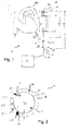
- a lung support system 1 is shown with a perfusion cannula 10, which can be arranged in the area of a heart 30 of a patient, in particular in an aorta 31 near an aortic arch 31a.
- the perfusion cannula 10 is coupled to an evaluation unit 20 via an electrical connection 18 and extends along a central longitudinal axis M. It has a distal end 10a (cannula tip) and a proximal end 10b.
- the perfusion cannula 10 is divided into two sections, a distal insertion section with an insertion length L1, and a proximal section, which are provided together over a total length L2 of the perfusion cannula 10.
- the perfusion cannula 10 has a cannula wall 12 which has a diameter D2 in the region of the proximal end 10b and a diameter D1 in the region of the distal end 10a.
- the diameter D1 is smaller than the diameter D2.
- the perfusion cannula 10 has a sensor lumen 16, indicated by dashed lines, in which an electrical line is routed, via which ring electrodes 17.1, 17.2 are electrically contacted.
- the ring electrodes 17.1, 17.2 are arranged on the outside of the cannula wall 12.
- the distal electrode 17.1 is arranged at a distance x1 from the distal end 10a, the distance x1, for example, in the range of 4 cm and the proximal electrode 17.2 is arranged at a distance x2 from the distal end 10a, so that the electrodes are arranged at a distance x3 of approximately 40 to 60 mm from one another.
- a perfusion cannula 10 is shown with a cannula wall 12, the cannula wall 12 having a cylindrical inner jacket surface 12a and a cylindrical outer jacket surface 12b, and the cylindrical inner jacket surface 12a delimits a perfusion lumen 13.
- the jacket surfaces 12a, 12b are arranged concentrically around a central longitudinal axis M.
- Five sensor lumens 16.1, 16.2, 16.3, 16.4, 16.5, which are arranged concentrically around the central longitudinal axis M, are integrated into the cannula wall 12.
- An EKG sensor 17 is embedded in a first of the sensor lumens 16.1, and a pressure sensor 19 is embedded in a fifth of the sensor lumens 16.5.
- the cannula wall 12 has a wall thickness d which is in the range of 0.75 mm, and the first sensor lumen 16.1 has a diameter d1 which is in the range of 0.25 mm, and the fifth sensor lumen 16.5 has a diameter d5 which is in the range of 0.55 mm.
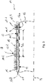
- a perfusion cannula 10 is shown with a cannula wall 12 which delimits a perfusion lumen 13.
- the perfusion cannula 10 extends along a central longitudinal axis M.
- a sensor lumen 16.1 for an EKG sensor 17 is integrated into the cannula wall 12, the EKG sensor 17 being embedded in the sensor lumen 16.1 in an embedding 11 so that a distal end 17a of the EKG sensor 17 is enclosed by the embedding 11.
- the EKG sensor 17 has two ring electrodes 17.1, 17.2 which are arranged around the cannula wall 12 at a distance x3 from one another.
- the ring electrodes 17.1, 17.2 are each connected to an electrical conductor 17b of the EKG sensor 17 via bushings 14.1, 14.2.
- the ring electrodes 17.1, 17.2 cover the bushings 14.1, 14.2.
- a wire reinforcement 15 is provided around the outside of the cannula wall 12, which is provided starting from a proximal end of the perfusion cannula 10 to the proximally arranged (second) ring electrode 17.2 and can optionally also be provided distal from the second ring electrode 17.2 as shown.
- the wire reinforcement 15 is preferably formed from two individual sections.
- a perfusion cannula 10 is shown which, in contrast to the one in FIG Fig. 3
- the perfusion cannula 10 shown does not have ring electrodes, but rather electrodes 17.1, 17.2 of an EKG sensor 17 arranged within a sensor lumen 16.1.
- the EKG sensor 17 is arranged completely in an embedding 11 and (only) sealed off from a distal end 10 a of the perfusion cannula 10.
- the perfusion cannula 10 therefore has no feedthroughs, and a wire reinforcement 15 is made in one piece and wound continuously around a cannula wall 12.
- Fig. 5 shows a perfusion cannula 10 with a perfusion lumen 13 and with a sensor lumen 16.5, in which a pressure sensor 19 is embedded in an embedding 11 within a cannula wall 12, a distal end 19a of the pressure sensor 19 in the distal direction from the embedding 11 in the area of a distal one
- the end 10a of the perfusion cannula 10 protrudes. This enables a pressure measurement to be carried out in a fiber-optic manner.
- the perfusion cannula 10 can, in addition to the sensor lumen 16.5 or the pressure sensor 19, as in FIG Fig. 3 and 4th shown have a sensor lumen or an EKG sensor.
- a perfusion cannula 10 with a cannula wall 12 is shown, the cannula wall 12 having an inner circumferential surface 12a and a cylindrical outer circumferential surface 12b, and the inner circumferential surface 12a delimits a perfusion lumen 13.
- Three lumens 16.1, 16.2, 16.5 are integrated into the cannula wall 12, a first sensor lumen 16.1 with an EKG sensor 17 arranged therein and a fifth sensor lumen 16.5 with a pressure sensor 19 arranged therein as well as with a free working lumen 16.2, in which, if required, an Working probe (not shown) can be arranged.
- the fifth sensor lumen 16.5 By arranging the fifth sensor lumen 16.5 in an inwardly protruding one Part of the cannula wall 12 is a wall thickness d of the cannula wall 12 with respect to a diameter d5 of the fifth sensor lumen 16.5 made comparatively thin, in particular with regard to a good flexibility of the perfusion cannula 10, even if a larger sensor lumen or working lumen should be required.
Landscapes
- Health & Medical Sciences (AREA)
- Life Sciences & Earth Sciences (AREA)
- Heart & Thoracic Surgery (AREA)
- Cardiology (AREA)
- Veterinary Medicine (AREA)
- General Health & Medical Sciences (AREA)
- Biomedical Technology (AREA)
- Public Health (AREA)
- Engineering & Computer Science (AREA)
- Animal Behavior & Ethology (AREA)
- Biophysics (AREA)
- Medical Informatics (AREA)
- Surgery (AREA)
- Molecular Biology (AREA)
- Physics & Mathematics (AREA)
- Pathology (AREA)
- Vascular Medicine (AREA)
- Hematology (AREA)
- Physiology (AREA)
- Anesthesiology (AREA)
- External Artificial Organs (AREA)
- Media Introduction/Drainage Providing Device (AREA)
- Measuring Fluid Pressure (AREA)
- Measurement And Recording Of Electrical Phenomena And Electrical Characteristics Of The Living Body (AREA)
- Measuring Pulse, Heart Rate, Blood Pressure Or Blood Flow (AREA)
Description
Die Erfindung betrifft eine Perfusionskanüle gemäß dem Oberbegriff des Anspruchs 1 zum Legen eines arteriellen oder venösen Zugangs, insbesondere in Verbindung mit einer Kreislaufersatztherapie.The invention relates to a perfusion cannula according to the preamble of
Eine Kreislaufersatztherapie kann z.B. mittels eines extrakorporalen Lungen-Unterstützungssystems erfolgen, mittels welchem einem Patienten Blut oder ein das Blut ersetzendes Fluid an einer Stelle (insbesondere venös) entnommen wird und an einer anderen Stelle (insbesondere arteriell) wieder zugeführt wird, nachdem es mit Sauerstoff angereichert wurde und/oder der Anteil an Kohlenstoffdioxid darin gesenkt wurde. Hierzu können so genannte Membranventilatoren verwendet werden, welche auch als Membranoxygenatoren bezeichnet werden. Das Blut/Fluid kann mittels Kanülen entnommen bzw. zugeführt werden.Circulatory replacement therapy can take place, for example, by means of an extracorporeal lung support system, by means of which blood or a fluid replacing the blood is taken from a patient at one point (especially venous) and fed back to another point (especially arterial) after it has been enriched with oxygen and / or the level of carbon dioxide therein has been reduced. So-called membrane fans, which are also referred to as membrane oxygenators, can be used for this purpose. The blood / fluid can be withdrawn or supplied by means of cannulas.
Mit dem Begriff "Perfusion" wird dabei die Versorgung von Organen mit Blut bezeichnet. Eine Organperfusion erfolgt auf natürliche Weise über Arterien und Venen, kann aber auch auf künstliche Weise erfolgen, z.B. über Bypässe oder extrakorporale Leitungen, die mittels Perfusionskanülen mit dem Organismus verbunden sein können. Perfusionskanülen werden häufig zur arteriellen Punktion eingesetzt, jedoch auch als venöse Perfusionskanülen. Sie stellen einen Versorgungskanal bereit, durch welche ein Fluid (z.B. Blut oder ein Blutersatzmittel) zu- oder abgeführt werden kann. Perfusionskanülen werden z.B. in Schocksituationen eines Menschen oder Tieres eingesetzt. In Schocksituationen ist dabei auch eine Überwachung des Vitalzustands von großer Bedeutung.The term "perfusion" refers to the supply of organs with blood. Organ perfusion occurs naturally via arteries and veins, but can also take place artificially, e.g. via bypasses or extracorporeal lines that can be connected to the organism by means of perfusion cannulas. Perfusion cannulas are often used for arterial puncture, but also as venous perfusion cannulas. They provide a supply channel through which a fluid (e.g. blood or a blood substitute) can be supplied or removed. Perfusion cannulas are used, for example, in shock situations in humans or animals. In shock situations, monitoring of the vital status is also of great importance.
Um den Vitalzustand eines Menschen oder Tieres einschätzen zu können, ist es zum einen wichtig, die Herzfunktion zu prüfen. Dies kann durch elektrisches Erfassen der elektrischen Aktivität des Herzmuskels erfolgen. Hierbei kann ein Elektro-Kardiogramm erstellt werden, also eine Herzspannungskurve. Das Elektro-Kardiogramm wird üblicherweise über eine Impedanzmessung mittels auf der Haut des Menschen/Tieres (im Folgenden "Patient") angebrachter (Klebe-)Elektroden aufgezeichnet. Eine EKG-Messung wird dabei z.B. durch einen hohen Hautwiderstand erschwert oder durch Klebeelektroden, die nur unzureichend auf der Haut haften (insbesondere aufgrund feuchter Haut). Auch besteht die Gefahr, dass die Haut durch die Elektroden verletzt wird. Die Messung ist auch dadurch erschwert, dass die Elektroden verrutschen können, was bei Gegenwehr oder instabiler Lagerung eines Patienten ein großes Problem sein kann.In order to be able to assess the vital status of a person or animal, it is important, on the one hand, to check the function of the heart. This can be done by electrically sensing the electrical activity of the heart muscle. Here, an electrocardiogram can be created, i.e. a cardiac voltage curve. The electrocardiogram is usually recorded via an impedance measurement by means of (adhesive) electrodes attached to the skin of the person / animal (hereinafter “patient”). An EKG measurement is made more difficult, for example, by high skin resistance or by adhesive electrodes that do not adhere adequately to the skin (especially due to damp skin). There is also the risk that the skin will be injured by the electrodes. The measurement is also made more difficult by the fact that the electrodes can slip, which can be a major problem in the event of resistance or unstable positioning of a patient.
Eine weitere wichtige Messung betrifft den Blutdruck des Patienten. Eine Blutdruckmessung kann z.B. auf invasive Weise erfolgen, indem mittels einer Kanüle ein Druck in einer der peripheren Arterien des Patienten, z.B. einer Arm- oder Beinarterie, erfasst wird. Eine Druckmessung erfordert ein separates Druckmesssystem, in welchem der Druck über eine Wassersäule zu einem Druckmesssystem erfasst wird und einem Monitoringsystem zur Überprüfung von Vitalfunktionen bzw. zur Diagnose des Patienten zugeführt wird. Bei einer peripheren Vasokonstriktion (Gefäßverengung), insbesondere in einer Schocksituation des Patienten, kann die für diese Druckmessung erforderliche Kanülierung meist nur schwer gelegt werden, da die dafür bevorzugten Stellen an Handgelenken und Ellenbeugen stark verengt sind, oder da Leistengefässe durch extrakorporale Verfahren belegt sind.Another important measurement is the patient's blood pressure. Blood pressure can be measured in an invasive manner, for example, by using a cannula to record a pressure in one of the patient's peripheral arteries, e.g. an artery in the arm or leg. A pressure measurement requires a separate pressure measurement system in which the pressure is recorded via a water column to a pressure measurement system and is fed to a monitoring system for checking vital functions or for diagnosing the patient. In the case of peripheral vasoconstriction (vasoconstriction), especially when the patient is in shock, the cannulation required for this pressure measurement can usually only be placed with difficulty because the preferred places on the wrists and elbows are severely narrowed, or because inguinal vessels are occupied by extracorporeal procedures.
Es ist eine Aufgabe der Erfindung, eine Perfusionskanüle bereitzustellen, welche die oben genannten Nachteile überwindet, insbesondere eine Perfusionskanüle mit verbesserter Funktionalität, z.B. in Schocksituationen eines zu therapierenden oder zu untersuchenden Patienten. Bevorzugt soll die Perfusionskanüle eine sichere Handhabung ermöglichen und/oder Funktionen auf besonders zuverlässige Weise erfüllen können. Weiter bevorzugt soll die Vorrichtung dabei auch robust im Hinblick auf Störeinflüsse sein.It is an object of the invention to provide a perfusion cannula which overcomes the above-mentioned disadvantages, in particular a perfusion cannula with improved functionality, e.g. in shock situations of a patient to be treated or examined. The perfusion cannula should preferably enable safe handling and / or be able to perform functions in a particularly reliable manner. More preferably, the device should also be robust with regard to interfering influences.
Zumindest eine der zuvor genannten Aufgaben wird durch eine Perfusionskanüle gemäß Anspruch 1 gelöst.At least one of the aforementioned objects is achieved by a perfusion cannula according to
Die Erfindung geht aus von einer Perfusionskanüle zum Legen eines Zugangs mit einer Kanülenwand und einem von der Kanülenwand umgrenzten Perfusionslumen, in welchem ein Fluidstrom die Perfusionskanüle durchströmen kann.The invention is based on a perfusion cannula for laying an access with a cannula wall and a perfusion lumen delimited by the cannula wall, in which a fluid stream can flow through the perfusion cannula.
Erfindungsgemäß ist vorgesehen, dass die Perfusionskanüle ferner wenigstens ein Sensorlumen und wenigstens eine Sensoreinrichtung umfasst, welche zumindest teilweise in dem Sensorlumen angeordnet ist. Hierdurch kann mittels der Sensoreinrichtung auch ein Erfassen von Vitalparametern erfolgen, insbesondere eines (Blut-)Drucks und/oder einer Herzspannungskurve, wobei die Vitalparameter innerhalb des Körpers des Patienten erfasst werden können, insbesondere in direkter Umgebung des Herzens. Die Vitalparameter können dadurch selbst dann zuverlässig erfasst werden, wenn eine Schocksituation des Patienten vorliegt, in welcher eine Verengung (Vasokonstriktion) peripherer, distaler Gefäße des Patienten erfolgt.According to the invention it is provided that the perfusion cannula further comprises at least one sensor lumen and at least one sensor device which is at least partially arranged in the sensor lumen. As a result, vital parameters can also be recorded by means of the sensor device, in particular (blood) pressure and / or a cardiac tension curve, with the vital parameters being able to be recorded within the patient's body, in particular in the immediate vicinity of the heart. The vital parameters can thus be reliably recorded even when the patient is in a shock situation in which a narrowing (vasoconstriction) of peripheral, distal vessels of the patient occurs.
Dabei ist nur eine einzige Kanülierung erforderlich, insbesondere eine femorale Kanülierung (im Oberschenkel- bzw. Leistenbereich). Mittels der Perfusionskanüle kann z.B. eine veno-arteriale Kreislaufunterstützung erfolgen, oder eine getriggerte diastolische Augmentation (Blutdruckerhöhung), oder allgemein eine Therapie in jeglicher Art von Schocksituationen (insbesondere kardiogen, spetisch, traumatisch), oder eine Reanimation. Dabei können simultan Vitalfunktionen überwacht werden.Only a single cannulation is required, in particular a femoral cannulation (in the thigh or groin area). The perfusion cannula can be used, for example, to provide veno-arterial circulatory support, or triggered diastolic augmentation (increase in blood pressure), or, in general, therapy in any kind of shock situation (especially cardiogenic, spetic, traumatic), or resuscitation. Vital functions can be monitored simultaneously.
Bevorzugt ist die Sensoreinrichtung ortsfest in Bezug auf ein (freies) distales Ende der Perfusionskanüle in dem Sensorlumen positioniert. Hierdurch wird dann die Position der Sensoreinrichtung relativ zum Patienten durch die Position der Perfusionskanüle insbesondere des distalen Endes hiervon vorgegeben. Besonders bevorzugt ist die Sensoreinrichtung in der Kanülenwand eingegossen oder darin eingebettet.The sensor device is preferably positioned in a stationary manner in relation to a (free) distal end of the perfusion cannula in the sensor lumen. As a result, the position of the sensor device relative to the patient is then predetermined by the position of the perfusion cannula, in particular the distal end thereof. The sensor device is particularly preferably cast into the cannula wall or embedded therein.
Als eine Perfusionskanüle ist dabei bevorzugt eine Vorrichtung zu verstehen, welche zum Legen eines Gefäß- oder Organzugangs für einen extrakorporalen Kreislauf ausgebildet ist und durch welche ein Fluid zu- oder abgeführt werden kann. Der Zugang kann dabei ein arterieller oder venöser Zugang sein, bevorzugt wird mit der Perfusionskanüle ein femoraler arterieller Zugang in einer Leistengegend des Patienten gelegt.A perfusion cannula is preferably to be understood as a device which is designed to provide a vascular or organ access for an extracorporeal circuit and through which a fluid can be supplied or removed. The access can be an arterial or venous access, preferably a femoral arterial access is made with the perfusion cannula in a groin area of the patient.
Als ein distales Ende ist dabei bevorzugt ein Ende der Perfusionskanüle zu verstehen, welches von einem Operateur weg weist und zu dem Patienten hinweist, also das Ende, welches in den Patienten eingebracht werden muss. Die Kanülengeometrie ist dabei bevorzugt so ausgelegt, dass möglichst kleine Übergänge an der Kanülenspitze vorhanden sind. Bevorzugt sind Übergänge kleiner als 0,1 mm.A distal end is preferably to be understood as an end of the perfusion cannula which points away from a surgeon and points to the patient, that is to say the end which has to be introduced into the patient. The cannula geometry is preferably designed in such a way that the smallest possible transitions are present at the cannula tip. Transitions smaller than 0.1 mm are preferred.
Das Sensorlumen kann wahlweise als eine in einer Längsrichtung der Perfusionskanüle durchgehende Aussparung, Öffnung, Ausnehmung oder Bohrung ausgebildet sein oder auch im Bereich eines distalen Endes der Perfusionskanüle abgeschottet sein, insbesondere nachdem eine entsprechende Sensoreinrichtung in dem Sensorlumen in einer geeigneten Position ortsfest angeordnet wurde. Dabei kann auch die Abschottung selbst die Sensoreinrichtung in dem Sensorlumen fixieren und lagern. Bevorzugt ist das Sensorlumen im Querschnitt kreisrund ausgebildet. Hierdurch kann eine Sensoreinrichtung auf einfache Weise durch das Sensorlumen geführt werden, ohne mit Kanten oder Hinterschneidungen zu kollidieren. Wahlweise weist das Sensorlumen eine elliptische oder andere runde Innenmantelfläche mit stetigen Übergängen auf, insbesondere in Übereinstimmung mit einer Querschnittsgeometrie einer korrespondierenden Sensoreinrichtung.The sensor lumen can optionally be designed as a recess, opening, recess or bore extending in a longitudinal direction of the perfusion cannula or it can also be sealed off in the area of a distal end of the perfusion cannula, in particular after a corresponding sensor device has been arranged in a suitable position in the sensor lumen. The partition itself can also fix and store the sensor device in the sensor lumen. The sensor lumen is preferably designed to be circular in cross section. As a result, a sensor device can be guided through the sensor lumen in a simple manner without colliding with edges or undercuts. The sensor lumen is optionally elliptical or round Inner jacket surface with continuous transitions, in particular in accordance with a cross-sectional geometry of a corresponding sensor device.
Dabei können ein oder mehrere Sensorlumina jeweils über einen Tauch- und Drehvorgang zusammen mit der Kanülenwand hergestellt werden. Dies kann durch einen schichtweisen Auftrag von Polymer, vergleichbar mit einem Kerzentauchen, oder mittels einer Dosiereinrichtung auf einem rotierenden Werkstückträger erfolgen. Hierbei können z.B. ein Verstärkungsdraht, ein Kabel, oder andere Komponenten eingearbeitet werden.One or more sensor lumens can be produced together with the cannula wall by means of a dipping and rotating process. This can be done by applying polymer in layers, comparable to dipping candles, or by means of a metering device on a rotating workpiece carrier. For example, a reinforcement wire, a cable or other components can be incorporated.
Gemäß einer Variante ist das Sensorlumen durch einen in die Kanülenwand eingebrachten Hohlraum entsprechend einem Platzhalter beim Herstellungsprozess (z.B. Extrusion) gebildet. Hierdurch kann ein Sensorlumen an einer frei wählbaren Position in der Kanülenwand vorgesehen werden, und die Anzahl der Sensorlumina kann je nach Bedarf frei gewählt werden, insbesondere auch nachdem die Kanülenwand der Perfusionskanüle bereits hergestellt wurde. Ein Sensorlumen kann dabei im Zusammenhang mit Extrusion, oder mit einem Platzhalter, der nach der Herstellung entfernt wird, oder durch Einarbeiten von vorgefertigten Hohlkörpern hergestellt werden.According to a variant, the sensor lumen is formed by a cavity made in the cannula wall in accordance with a placeholder during the manufacturing process (e.g. extrusion). As a result, a sensor lumen can be provided at a freely selectable position in the cannula wall, and the number of sensor lumens can be freely selected as required, in particular also after the cannula wall of the perfusion cannula has already been produced. A sensor lumen can be produced in connection with extrusion, or with a placeholder that is removed after production, or by incorporating prefabricated hollow bodies.
Gemäß einer bevorzugten Ausführungsform ist wenigstens ein Sensorlumen in die Kanülenwand integriert oder in radialer Richtung seitlich hervorstehend, insbesondere nach innen in das Perfusionslumen hervorstehend, an der Kanülenwand angeordnet. Durch ein integriertes Sensorlumen kann sichergestellt werden, dass die Funktion der Perfusionskanüle zum Entnehmen oder Zuführen des Fluids nicht beeinträchtigt wird. Durch ein nach innen in das Perfusionslumen hervorstehendes Sensorlumen kann sichergestellt werden, dass auch Sensoreinrichtungen, die im Durchmesser größer als die Wanddicke der Kanülenwand sind, in Verbindung der Persfusionskanüle genutzt werden können. Eine Anordnung seitlich innen an der Kanüle liefert den Vorteil einer einfachen Herstellbarkeit oder auch guter Strömungseigenschaften, insbesondere da die Kanülenwand dünner ausgeführt werden kann und damit höhere Durchflüsse bei einem bestimmten Kanülen-Außendurchmesser erzielt werden können.According to a preferred embodiment, at least one sensor lumen is integrated into the cannula wall or is arranged on the cannula wall protruding laterally in the radial direction, in particular protruding inward into the perfusion lumen. An integrated sensor lumen can ensure that the function of the perfusion cannula for removing or supplying the fluid is not impaired. A sensor lumen protruding inward into the perfusion lumen can ensure that sensor devices which are larger in diameter than the wall thickness of the cannula wall can also be used in connection with the persfusion cannula. An arrangement laterally on the inside of the cannula has the advantage of being easy to manufacture or also of good flow properties, in particular since the Cannula wall can be made thinner and thus higher flow rates can be achieved with a certain cannula outer diameter.
Als ein in die Kanülenwand integriertes Sensorlumen ist dabei ein Lumen zu verstehen, welches innerhalb der Kanülenwand vorgesehen ist, ohne dass der Kanülenwand dafür eine besondere von der eigentlichen Kanülenwandgeometrie abweichende Geometrie verliehen wird. Ist die Kanülenwand z.B. als hohlzylindrischer Körper ausgebildet, so ist das Sensorlumen zwischen den beiden zylindrischen Mantelflächen vorgesehen, ohne dass von der zylindrischen Geometrie abgewichen werden muss. Ein in die Kanülenwand integriertes Sensorlumen weist damit einen Durchmesser auf, welcher kleiner ist als die Dicke der Kanülenwand.A sensor lumen integrated into the cannula wall is to be understood as a lumen which is provided within the cannula wall without the cannula wall being given a special geometry deviating from the actual cannula wall geometry. If the cannula wall is designed as a hollow cylindrical body, for example, the sensor lumen is provided between the two cylindrical outer surfaces without having to deviate from the cylindrical geometry. A sensor lumen integrated into the cannula wall thus has a diameter which is smaller than the thickness of the cannula wall.
Die Kanülenwand ist mit einer zumindest annähernd zylindrischen inneren Seite einer umlaufenden Innenmantelfläche ausgebildet. Weiter ist die Kanülenwand mit einer zumindest annähernd zylindrischen äußeren Seite einer umlaufenden Außenmantelfläche ausgebildet. Dies liefert, da beide Mantelflächen konzentrisch angeordnet sind, richtungsunabhängige Biegeeigenschaften und Steifigkeiten der Perfusionskanüle. Auch kann der Durchmesser der Perfusionskanüle bei dieser Querschnittsgeometrie auf einfache Weise entlang der Längserstreckung der Perfusionskanüle variabel ausgeführt sein, insbesondere bei einer sich verjüngenden Perfusionskanüle.The cannula wall is formed with an at least approximately cylindrical inner side of a circumferential inner jacket surface. Furthermore, the cannula wall is designed with an at least approximately cylindrical outer side of a circumferential outer jacket surface. Since both lateral surfaces are arranged concentrically, this provides direction-independent bending properties and rigidity of the perfusion cannula. With this cross-sectional geometry, the diameter of the perfusion cannula can also be designed to be variable in a simple manner along the longitudinal extent of the perfusion cannula, in particular in the case of a tapering perfusion cannula.
Gemäß einer bevorzugten Ausführungsform weist die Perfusionskanüle eine Einführlänge von mehr als 15 cm, bevorzugt mehr als 20 cm, weiter bevorzugt mehr als 25 cm, insbesondere im Bereich von 25 bis 50 cm auf. Hierdurch kann eine arterielle Perfusionskanüle bereitgestellt werden, welche auch in einem Leistenbereich eines Patienten eingebracht werden kann, und deren distales Ende bis in die Nähe des Herzens des Patienten gelangen kann.According to a preferred embodiment, the perfusion cannula has an insertion length of more than 15 cm, preferably more than 20 cm, more preferably more than 25 cm, in particular in the range from 25 to 50 cm. In this way, an arterial perfusion cannula can be provided which can also be introduced into a groin area of a patient, and the distal end of which can reach the vicinity of the patient's heart.
Als Einführlänge ist dabei die Länge des Abschnitts der Perfusionskanüle zu verstehen, welcher maximal in einen Patienten eingeführt werden kann. Bei einer arteriellen Perfusionskanüle ist die Einführlänge bevorzugt deutlich größer als 25 cm und liegt z.B. im Bereich von 45 bis 50 cm. Zumindest über die Einführlänge weist die Perfusionskanüle bevorzugt eine Beschichtung mit guten Gleiteigenschaften an Gewebeoberflächen auf. Die Beschichtung kann eine Polyurethanbeschichtung sein.The insertion length is to be understood as the length of the section of the perfusion cannula which can maximally be inserted into a patient. At a arterial perfusion cannula, the insertion length is preferably significantly greater than 25 cm and is, for example, in the range from 45 to 50 cm. At least over the insertion length, the perfusion cannula preferably has a coating with good sliding properties on tissue surfaces. The coating can be a polyurethane coating.
Bevorzugt weist die Perfusionskanüle eine Gesamtlänge im Bereich von 20 bis 100, weiter bevorzugt 25 bis 75 cm auf. Als Gesamtlänge ist dabei die Länge der Perfusionskanüle von einem distalen Ende (Kanülenspitze) zu einem proximalen Ende zu verstehen, wobei die Perfusionskanüle an dem proximalen Ende mit einer Konsole, insbesondere einer Auswerteeinheit gekoppelt sein kann. Die Gesamtlänge ist größer als die Einführlänge, so dass ein Operateur die Perfusionskanüle jedenfalls handhaben kann, auch wenn sie über die maximale Einführlänge eingeführt ist. Bevorzugt ist die Gesamtlänge mindestens um 10 cm, bevorzugt mindestens 15 cm größer als die Einführlänge.The perfusion cannula preferably has a total length in the range from 20 to 100, more preferably 25 to 75 cm. The total length is to be understood as the length of the perfusion cannula from a distal end (cannula tip) to a proximal end, wherein the perfusion cannula can be coupled to a console, in particular an evaluation unit, at the proximal end. The total length is greater than the insertion length, so that a surgeon can handle the perfusion cannula in any case, even if it is inserted over the maximum insertion length. The total length is preferably at least 10 cm, preferably at least 15 cm, greater than the insertion length.
Bevorzugt ist die Perfusionskanüle dabei als arterielle Perfusionskanüle zum Einbringen in eine Arterie ausgebildet. Eine solche arterielle Perfusionskanüle weist bevorzugt keine radialen Aussparungen oder Löcher in der Kanülenwand auf, sondern lediglich am distalen Ende eine Öffnung, über welche einem Patienten Blut oder ein anderes Fluid zugeführt werden kann. Radiale Aussparungen oder Löcher in der Kanülenwand können jedoch bei venösen Perfusionskanülen vorgesehen sein, insbesondere um einem Patienten eine größere Menge an Blut oder Fluid pro Zeiteinheit entnehmen zu können (Erhöhung der Drainageleistung), insbesondere auch um eine entlastende Wirkung für das Herz bereitstellen zu können. Bei venösen Perfusionskanülen können z.B. zehn radiale Aussparungen oder Löcher vorgesehen sein, insbesondere in einem distalen Bereich der Perfusionskanüle, um Blut/Fluid direkt am Herzen entziehen zu können, insbesondere direkt aus dem Vorhof des Herzens oder der oberen Hohlvene (vena cava superior). Wahlweise weist auch die arterielle Perfusionskanüle ein oder zwei kleine radiale Löcher oder Aussparungen auf, aber deutlich weniger oder kleinere Löcher als eine venöse Perfusionskanüle. Hierdurch kann Blut nicht nur der Kanülenspitze, sondern auch seitlich davon zugeführt werden. Auch kann eine gute Durchblutung von Bauchorganen sichergestellt werden, und es können geringere Strömungsgeschwindigkeiten eingestellt werden. Die Löcher weisen bevorzugt einen Durchmesser von 0,5-5 mm, weiter bevorzugt 1-3 mm auf.The perfusion cannula is preferably designed as an arterial perfusion cannula for introduction into an artery. Such an arterial perfusion cannula preferably has no radial recesses or holes in the cannula wall, but only an opening at the distal end through which blood or another fluid can be supplied to a patient. Radial recesses or holes in the cannula wall can, however, be provided in venous perfusion cannulas, in particular in order to be able to withdraw a larger amount of blood or fluid from a patient per unit of time (increase of the drainage capacity), in particular to be able to provide a relief effect for the heart. In venous perfusion cannulas, ten radial recesses or holes can be provided, in particular in a distal area of the perfusion cannula, in order to be able to withdraw blood / fluid directly from the heart, in particular directly from the atrium of the heart or the superior vena cava (superior vena cava). Optionally, the arterial perfusion cannula also has one or two small radial holes or recesses, but significantly fewer or smaller holes than a venous perfusion cannula. As a result, blood can be fed not only to the cannula tip, but also to the side of it. Also can have good blood circulation from Abdominal organs are ensured, and lower flow velocities can be set. The holes preferably have a diameter of 0.5-5 mm, more preferably 1-3 mm.
Gemäß einer bevorzugten Ausführungsform weist die Perfusionskanüle im Bereich eines distalen Endes der Perfusionskanüle einen Außendurchmesser zwischen 5 und 35 French (Fr) entsprechend etwa 1,7 und 11,7 mm, bevorzugt zwischen 12 und 25 French (Fr) entsprechend etwa 4 und 8,4 mm auf. Hierdurch kann eine besonders schmale, dünne und flexible Perfusionskanüle bereitgestellt werden, welche auch eine Diagnostikfunktion übernehmen kann. Der Patient wird mittels der erfindungsgemäßen Perfusionskanüle nicht stärker belastet als bei einer herkömmlichen Kanüle, insbesondere weil eine Inzision zum Einbringen der Perfusionskanüle trotz der zusätzlichen Sensoreinrichtung(en) klein bleiben kann.According to a preferred embodiment, the perfusion cannula in the area of a distal end of the perfusion cannula has an outer diameter between 5 and 35 French (Fr) corresponding to about 1.7 and 11.7 mm, preferably between 12 and 25 French (Fr) corresponding to about 4 and 8, 4 mm. This makes it possible to provide a particularly narrow, thin and flexible perfusion cannula which can also take on a diagnostic function. The patient is not more stressed by means of the perfusion cannula according to the invention than with a conventional cannula, in particular because an incision for introducing the perfusion cannula can remain small despite the additional sensor device (s).
Als Bereich eines distalen Endes ist dabei ein Abschnitt der Perfusionskanüle zu verstehen, welcher sich über eine Länge von maximal 5 cm, bevorzugt maximal 3 cm von einem distalen Ende der Perfusionskanüle in proximaler Richtung erstreckt.The area of a distal end is to be understood as a section of the perfusion cannula which extends over a length of at most 5 cm, preferably at most 3 cm, from a distal end of the perfusion cannula in the proximal direction.
Bevorzugt ist die Wandungsdicke der Perfusionskanüle entlang der gesamten Einführlänge unter 2 mm, bevorzugt unter 1 mm, weiter bevorzugt unter 0,5 mm. Hierdurch kann eine Perfusionskanüle, insbesondere eine arterielle Perfusionskanüle bereitgestellt werden, welche trotz einer bedeutenden Länge flexibel ist und leicht gehandhabt werden kann und von einer Leistengegend bis zu dem Herzen eines Patienten vorgeschoben werden kann.The wall thickness of the perfusion cannula along the entire insertion length is preferably less than 2 mm, preferably less than 1 mm, more preferably less than 0.5 mm. This makes it possible to provide a perfusion cannula, in particular an arterial perfusion cannula, which, despite a considerable length, is flexible and easy to handle and can be advanced from a groin area to the heart of a patient.
Bevorzugt weist die Perfusionskanüle im Bereich eines proximalen Endes der Perfusionskanüle einen Außendurchmesser zwischen 5 und 35 French, bevorzugt zwischen 12 und 25 French auf. Hierdurch kann ein proximales Ende bereitgestellt werden, welches stabil ist, so dass eine Kanülenspitze auch über eine größere Einführlänge durch eine Arterie oder Vene geschoben werden kann. Bevorzugt verjüngt sich die Perfusionskanüle im Einführabschnitt, insbesondere kontinuierlich über die Einführlänge. Die Verjüngung ist dabei bevorzugt in einem Konnektorbereich der Perfusionskanüle vorgesehen oder besonders stark ausgeprägt. Der Außendurchmesser ist im Bereich der Einführlänge bevorzugt konstant. Eine Verjüngung liegt bevorzugt an der Kanülenspitze vor.The perfusion cannula preferably has an outer diameter between 5 and 35 French, preferably between 12 and 25 French, in the region of a proximal end of the perfusion cannula. This makes it possible to provide a proximal end which is stable so that a cannula tip can also be pushed through an artery or vein over a greater insertion length. The perfusion cannula preferably tapers in the insertion section, in particular continuously over the insertion length. The taper is preferably in a connector area the perfusion cannula provided or particularly pronounced. The outer diameter is preferably constant in the region of the insertion length. A taper is preferably present at the cannula tip.
Gemäß einer bevorzugten Ausführungsform ist wenigstens eine der wenigstens einen Sensoreinrichtung als EKG-Sensor ausgebildet. Das (EKG-)Sensorlumen kann einen Durchmesser zwischen 0,05 und 2 mm, bevorzugt 0,2 und 0,5 mm aufweisen. Der EKG-Sensor kann dabei im Wesentlichen durch zwei Elektroden und die Elektroden elektrisch kontaktierende Leitungen gebildet sein. Hierdurch kann eine EKG-Messung mittels eines besonders kleinen Sensors erfolgen, der in dem Sensorlumen geführt werden kann. Ein Innendurchmesser des Sensorlumens, welcher auf den Außendurchmesser des EKG-Sensors abgestimmt ist, erleichtert die Montage des EKG-Sensors in der Perfusionskanüle. Es kann z.B. verhindert werden, dass der EKG-Sensor im Sensorlumen verkantet. Dabei kann eine dünne Kanülenwand mit guter Flexibilität (mit guten elastischen Eigenschaften) bereitgestellt werden, die trotz des Sensorlumens eine gute Stabilität aufweist. Bei einer geringen Wandstärke entsteht nur ein geringer Druckverlust.According to a preferred embodiment, at least one of the at least one sensor device is designed as an EKG sensor. The (EKG) sensor lumen can have a diameter between 0.05 and 2 mm, preferably 0.2 and 0.5 mm. The EKG sensor can essentially be formed by two electrodes and lines that make electrical contact with the electrodes. This allows an EKG measurement to take place using a particularly small sensor that can be guided in the sensor lumen. An inner diameter of the sensor lumen, which is matched to the outer diameter of the EKG sensor, facilitates the installation of the EKG sensor in the perfusion cannula. For example, it can be prevented that the ECG sensor tilts in the sensor lumen. A thin cannula wall with good flexibility (with good elastic properties) can be provided, which has good stability despite the sensor lumen. With a small wall thickness, there is only a slight loss of pressure.
Eine solche Perfusionskanüle mit einem EKG-Sensor kann für eine arterielle EKG-Messung vorgesehen sein, also eine EKG-Messung, bei welcher die Perfusionskanüle durch eine Arterie bis in die Nähe des Herzens eines Patienten eingebracht wird, insbesondere über die Leistengegend, ohne dass z.B. ein Brust- oder Bauchbereich des Patienten chirurgisch geöffnet werden muss. Der EKG-Sensor ist bevorzugt bipolar messend ausgebildet. Der EKG-Sensor kann mit einem proximalen Ende an eine Auswerteeinheit angeschlossen sein, z.B. über eine zugsichere Steckverbindung.Such a perfusion cannula with an EKG sensor can be provided for an arterial EKG measurement, that is to say an EKG measurement in which the perfusion cannula is introduced through an artery into the vicinity of the patient's heart, in particular over the groin area, without e.g. a chest or stomach area of the patient needs to be surgically opened. The EKG sensor is preferably designed to measure bipolarly. The proximal end of the EKG sensor can be connected to an evaluation unit, e.g. via a secure plug connection.
Gemäß einer bevorzugten Ausführungsform ist die wenigstens eine der wenigstens einen Sensoreinrichtung als EKG-Sensor ausgebildet und weist eine Ringelektrode auf, die außen um die Kanülenwand angeordnet ist und über eine Durchführung in der Kanülenwand mittels eines in dem entsprechenden Sensorlumen geführten elektrischen Leiters elektrisch kontaktiert ist. Hierdurch kann ein EKG-Sensor bereitgestellt werden, mittels welchem die Elektroden besonders nah in den Bereich des Herzens gebracht werden können. Dies ermöglicht eine genaue Messung. Die Materialwahl für die Perfusionskanüle kann weitgehend unabhängig von der elektrischen Funktion der Elektroden erfolgen. Die Elektroden können gegenüber der Kanüle elektrisch isoliert sein. Ferner ist die Messung unabhängig von einer Verdrehung der Perfusionskanüle um eine Mittenlängsachse der Perfusionskanüle, da die Ringelektroden umlaufend vorgesehen sind und in allen Richtungen einer Ebene senkrecht zu der Mittenlängsachse eine Messung durchführen können. Hierdurch ist die Handhabung der EKG-Messung besonders einfach und sicher. Eine zuverlässige Messung kann jedenfalls sichergestellt werden, unabhängig von dem Zustand des Patienten oder der Ausrichtung der Perfusionskanüle. Die Elektrode besteht bevorzugt aus einem biokompatiblen Material.According to a preferred embodiment, the at least one of the at least one sensor device is designed as an EKG sensor and has a ring electrode which is arranged around the outside of the cannula wall and is electrically contacted via a passage in the cannula wall by means of an electrical conductor guided in the corresponding sensor lumen. This enables an EKG sensor can be provided, by means of which the electrodes can be brought particularly close to the area of the heart. This enables an accurate measurement. The choice of material for the perfusion cannula can be made largely independently of the electrical function of the electrodes. The electrodes can be electrically isolated from the cannula. Furthermore, the measurement is independent of a rotation of the perfusion cannula about a central longitudinal axis of the perfusion cannula, since the ring electrodes are provided circumferentially and can carry out a measurement in all directions of a plane perpendicular to the central longitudinal axis. This makes handling the EKG measurement particularly easy and safe. A reliable measurement can be ensured in any case, regardless of the patient's condition or the orientation of the perfusion cannula. The electrode is preferably made of a biocompatible material.
Die Ringelektrode kann unmittelbar mit einer elektrischen Leitung verbunden sein, welche durch das Sensorlumen geführt ist und mit einer Auswerteeinheit verbindbar ist. Die elektrische Leitung kann z.B. ein 3-5 poliges Kabel sein. Wahlweise kann die Ringelektrode auch mit einem weiteren Teil der EKG-Sensoreinrichtung gekoppelt sein, welche wiederum mit der Auswerteeinheit gekoppelt ist, insbesondere über eine elektrische Leitung. Die elektrische Leitung kann in dem Sensorlumen eingebettet sein.The ring electrode can be connected directly to an electrical line which is passed through the sensor lumen and can be connected to an evaluation unit. The electrical line can be, for example, a 3-5 pole cable. Optionally, the ring electrode can also be coupled to a further part of the EKG sensor device, which in turn is coupled to the evaluation unit, in particular via an electrical line. The electrical line can be embedded in the sensor lumen.
Die Elektrode bzw. Ringelektrode ist bevorzugt eine passive Elektrode, die mit einer Leitung (einer von der Elektrode wegführenden Leitung) gekoppelt ist. Es können z.B. 3-5 polige Leitungen bzw. Kabel vorgesehen sein.The electrode or ring electrode is preferably a passive electrode which is coupled to a line (a line leading away from the electrode). For example, 3-5 pole lines or cables can be provided.
Bevorzugt weist die Perfusionskanüle zwei Elektroden oder Ringelektroden auf, welche in einem vorgegebenen Abstand zueinander angeordnet sind, insbesondere im Bereich von 5 bis 200 mm, bevorzugt von 30 bis 80 mm. Hierdurch kann eine Herzspannungskurve mit großer Genauigkeit aufgenommen werden, insbesondere da die Elektroden immer in einem vordefinierten Abstand zueinander angeordnet sind. Eine Fehlbedienung, wie z.B. beim Aufkleben von Elektroden auf den Brustkorb in nicht optimalen Positionen, kann vermieden werden.The perfusion cannula preferably has two electrodes or ring electrodes which are arranged at a predetermined distance from one another, in particular in the range from 5 to 200 mm, preferably from 30 to 80 mm. In this way, a cardiac voltage curve can be recorded with great accuracy, in particular since the electrodes are always arranged at a predefined distance from one another. Incorrect operation, such as sticking electrodes on the chest in non-optimal positions, can be avoided.
Gemäß einer bevorzugten Ausführungsform ist die wenigstens eine der wenigstens einen Sensoreinrichtung als EKG-Sensor mit zwei innerhalb des Sensorlumens angeordneten Elektroden ausgebildet. Hierdurch kann eine besonders einfach herzustellende Perfusionskanüle bereitgestellt werden. Elektrische Durchführungen nach außen sind nicht erforderlich. Die Perfusionskanüle kann dabei mit einer zumindest im Wesentlichen ebene Außenmantelfläche ausgeführt sein, welche keine Kanten, Erhebungen oder Unstetigkeiten aufweist, so dass die Perfusionskanüle zum einen in Bezug auf ihre Mittenlängsachse gleiche Biegeeigenschaften aufweist, zum anderen auch mit geringem Widerstand in einer Arterie oder Vene verschoben werden kann.According to a preferred embodiment, the at least one of the at least one sensor device is designed as an EKG sensor with two electrodes arranged within the sensor lumen. This makes it possible to provide a perfusion cannula that is particularly easy to manufacture. Electrical feedthroughs to the outside are not required. The perfusion cannula can be designed with an at least essentially flat outer jacket surface that has no edges, elevations or discontinuities, so that the perfusion cannula has the same bending properties with respect to its central longitudinal axis on the one hand, and is also displaced in an artery or vein with little resistance on the other can be.
Bevorzugt sind die Elektroden bzw. Ringelektroden in einem vorgegebenen Abstand zu einem distalen Ende der Perfusionskanüle positioniert. Hierdurch kann eine Positionierung der Elektroden über eine Position des distalen Endes der Perfusionskanüle erfolgen. Das distale Ende kann dabei in dem Aortenbogen der thorakalen Aorta (im Brustkorbbereich) angeordnet werden, wobei der Abstand der Elektroden von dem distalen Ende derart festgelegt ist, dass die Elektroden in einer messtechnisch zweckdienlichen Position in Bezug auf das Herz angeordnet werden.The electrodes or ring electrodes are preferably positioned at a predetermined distance from a distal end of the perfusion cannula. This allows the electrodes to be positioned via a position of the distal end of the perfusion cannula. The distal end can be arranged in the aortic arch of the thoracic aorta (in the thoracic area), the distance between the electrodes and the distal end being set in such a way that the electrodes are arranged in a metrologically expedient position in relation to the heart.
Wenigstens eine der wenigstens einen Sensoreinrichtung ist als Drucksensor ausgebildet. Bevorzugt sind dabei mindestens zwei Sensorlumina vorgesehen und in dem anderen Sensorlumen ist ein EKG-Sensor angeordnet. Hierdurch ist eine schnelle und effiziente Erfassung von mehreren Vitalparametern möglich, und dabei ist nur ein einziger Gefäßzugang erforderlich, insbesondere ein arterieller Zugang. Die Perfusionskanüle kann sowohl zum Erfassen einer Herzspannungskurve als auch eines Blutdrucks verwendet werden. Dabei ist für die Erfassung von mindestens zwei Vitalparametern auch nur eine einzige Kanülierung erforderlich. Die Gefahr von Störeinflüssen kann verringert werden, insbesondere weil in vivo gemessen werden kann. Auch können weitere Vitalparameter, insbesondere ein Blutdruck, in direkter Umgebung des Herzens erfasst werden. Die Kanüle kann dabei (insbesondere zeitgleich) zum einen für die Messung der Vitalparameter, zum anderen aber auch ohne besondere Einschränkung als Perfusionskanüle für den extrakorporalen Kreislauf eingesetzt werden. Die Kanülenwand ist lediglich etwas dicker ausgeführt als bei einer herkömmlichen Perfusionskanüle, und ist möglicherweise etwas steifer.At least one of the at least one sensor device is designed as a pressure sensor. At least two sensor lumens are preferably provided and an EKG sensor is arranged in the other sensor lumen. This enables a number of vital parameters to be recorded quickly and efficiently, and only a single vascular access is required, in particular an arterial access. The perfusion cannula can be used both for recording a cardiac voltage curve and a blood pressure. Only a single cannulation is required to record at least two vital parameters. The risk of interference can be reduced, in particular because measurements can be carried out in vivo. Further vital parameters, in particular blood pressure, can also be recorded in the immediate vicinity of the heart. The cannula can be used (in particular at the same time) on the one hand for measuring the vital parameters, but on the other hand as a perfusion cannula for the extracorporeal one without any particular restriction Circulation are used. The cannula wall is only made somewhat thicker than in the case of a conventional perfusion cannula, and is possibly somewhat stiffer.
Erfindungsgemäß ist das Sensorlumen zur Aufnahme des Drucksensors in die Kanülenwand integriert. Dabei können nicht nur zwei, sondern auch noch weitere Sensorlumina vorgesehen sein, z.B. drei bis fünf Sensorlumina.According to the invention, the sensor lumen for receiving the pressure sensor is integrated into the cannula wall. Not only two, but also further sensor lumens can be provided, e.g. three to five sensor lumens.
Gemäß einer bevorzugten Variante sind die Sensorlumina konzentrisch um eine Mittenlängsachse der Perfusionskanüle angeordnet. Hierdurch kann eine Perfusionskanüle bereitgestellt werden, bei welcher die Auswahl eines bestimmten Sensorlumens für einen bestimmten Sensor ohne Einfluss auf die Messung ist, d.h., bei einer Messung muss eine Anordnung des Sensors in der Kanüle relativ zu der Kanülenwand nicht berücksichtigt werden, insbesondere weil die Lumina in demselben Abstand zu einer Außenmantelfläche der Perfusionskanüle angeordnet sind. Dies erleichtert auch eine Herstellung der Perfusionskanüle, insbesondere bei einer großen Anzahl von Sensorlumina, z.B. fünf Sensorlumina. Bevorzugt sind die Sensorlumina in einem gleichbleibenden Abstand zueinander über den Umfang verteilt angeordnet und dabei auf den gesamten Umfang bezogen symmetrisch angeordnet. Dadurch kann eine Perfusionskanüle bereitgestellt werden, welche in allen Raumrichtungen dieselbe Biegesteifigkeit um ihre Mittenlängsachse aufweist, zumindest wenn die Sensorlumina denselben (Innen-)Durchmesser aufweisen, und dadurch leichter gehandhabt werden kann.According to a preferred variant, the sensor lumens are arranged concentrically around a central longitudinal axis of the perfusion cannula. In this way, a perfusion cannula can be provided in which the selection of a specific sensor lumen for a specific sensor has no influence on the measurement, that is, during a measurement, an arrangement of the sensor in the cannula relative to the cannula wall does not have to be taken into account, in particular because the lumina are arranged at the same distance from an outer jacket surface of the perfusion cannula. This also makes it easier to manufacture the perfusion cannula, especially when there is a large number of sensor lumens, e.g. five sensor lumens. The sensor lumens are preferably arranged distributed over the circumference at a constant distance from one another and are arranged symmetrically over the entire circumference. As a result, a perfusion cannula can be provided which has the same flexural rigidity around its central longitudinal axis in all spatial directions, at least if the sensor lumens have the same (inner) diameter and can therefore be handled more easily.
Bevorzugt ist die Kanülenwand im Querschnitt ringförmig ausgebildet und weist eine Breite bzw. Wandstärke unter 2 mm, bevorzugt unter 1 mm, weiter bevorzugt unter 0,5 mm auf. Hierdurch kann eine Perfusionskanüle mit einer möglichst schmalen Kanülenwand bereitgestellt werden, welche flexibel ist und auch in alle Raumrichtungen auf dieselbe Weise gebogen werden kann.The cannula wall is preferably annular in cross section and has a width or wall thickness of less than 2 mm, preferably less than 1 mm, more preferably less than 0.5 mm. In this way, a perfusion cannula can be provided with a cannula wall that is as narrow as possible, which is flexible and can also be bent in the same way in all spatial directions.
Gemäß einer bevorzugten Ausführungsform ist der Drucksensor als faseroptischer Drucksensor ausgebildet. Hierdurch kann ein besonders kompakter Drucksensor bereitgestellt werden, der auf zweckdienliche Weise in ein kleines Lumen einer Perfusionskanüle integrierbar ist, ohne dass die Handhabung der Perfusionskanüle spürbar erschwert wird. Die Messung kann ohne Flüssigkeiten erfolgen, sie kann mit hoher Messgenauigkeit erfolgen, und die Messung ist wenig fehleranfällig. Wahlweise kann eine Messung über eine Wassersäule erfolgen.According to a preferred embodiment, the pressure sensor is designed as a fiber-optic pressure sensor. In this way, a particularly compact pressure sensor can be provided which is expediently inserted into a small lumen of a Perfusion cannula can be integrated without making handling of the perfusion cannula noticeably difficult. The measurement can be carried out without liquids, it can be carried out with high measuring accuracy, and the measurement is not prone to errors. Optionally, a measurement can be made using a water column.
Bevorzugt ist wenigstens ein Sensorlumen für einen faseroptischen Drucksensor vorgesehen und als beidseitig offener Kanal ausgebildet. Der Drucksensor kann z.B. in einer Einbettung (insbesondere einem transparenten Polymer) gelagert sein, welche auch eine Abdichtung sicherstellen kann. Wahlweise kann auch allein oder zusätzlich ein Schott durch einen Stopfen oder eine Wandung aus einem elastischen Material wie z.B. Silikon gebildet sein, wobei der Stopfen bzw. die Wandung im Bereich des distalen Endes der Sensoreinrichtung vorgesehen sein kann.At least one sensor lumen is preferably provided for a fiber-optic pressure sensor and is designed as a channel that is open on both sides. The pressure sensor can, for example, be embedded in an embedding (in particular a transparent polymer), which can also ensure a seal. Optionally, a bulkhead can also be formed solely or in addition by a plug or a wall made of an elastic material such as silicone, wherein the plug or the wall can be provided in the area of the distal end of the sensor device.
Bevorzugt ist wenigstens ein Sensorlumen für einen möglichst kleinen, optisch messenden, faserbasierten Sensor vorgesehen, z.B. für einen Drucksensor des kanadischen Unternehmens FISO Technologies. Solche Sensoren können einen Durchmesser im Bereich von nur 200 µm oder noch weniger aufweisen. Sie erfordern keine Wassersäule und auch keine separate Halteplatte. Sie sind z.B. aus einem Glasmaterial hergestellt und können biokompatibel ausgeführt sein. Der Drucksensor selbst ist bevorzugt an der Spitze der Sensoreinrichtung angeordnet. Druckunterschiede oder Druckänderungen können sehr schnell und mit guter Genauigkeit erfasst werden.At least one sensor lumen is preferably provided for an optically measuring, fiber-based sensor that is as small as possible, e.g. for a pressure sensor from the Canadian company FISO Technologies. Such sensors can have a diameter in the range of only 200 μm or even less. They do not require a water column or a separate retaining plate. For example, they are made of a glass material and can be made biocompatible. The pressure sensor itself is preferably arranged at the tip of the sensor device. Differences in pressure or changes in pressure can be recorded very quickly and with good accuracy.
Bevorzugt weist das Druck-Sensorlumen einen Durchmesser im Bereich von 0,3 bis 0,8 mm, bevorzugt 0,4 bis 0,7 mm, besonders bevorzugt 0,5 bis 0,6 mm, insbesondere 0,55 mm auf.The pressure sensor lumen preferably has a diameter in the range from 0.3 to 0.8 mm, preferably 0.4 to 0.7 mm, particularly preferably 0.5 to 0.6 mm, in particular 0.55 mm.
Gemäß einer bevorzugten Ausführungsform weist der faseroptische Drucksensor ein distales Ende auf, welches in einem Abstand von maximal 5 cm, bevorzugt maximal 3 cm, weiter bevorzugt maximal 1 cm von einem distalen Ende der Perfusionskanüle angeordnet ist. Hierdurch kann die Druckmessung an einem über die Position des distalen Endes der Perfusionskanüle vorgebbaren Punkt erfolgen. Wahlweise kann eine seitliche Durchführung durch die Kanülenwand erfolgen, z.B. wie bei Durchführungen für die elektrischen Leitungen zu Ringelektroden.According to a preferred embodiment, the fiber-optic pressure sensor has a distal end which is arranged at a distance of a maximum of 5 cm, preferably a maximum of 3 cm, more preferably a maximum of 1 cm from a distal end of the perfusion cannula. As a result, the pressure measurement can take place at a point that can be predetermined via the position of the distal end of the perfusion cannula. Optionally can a lateral passage through the cannula wall, for example as in the case of bushings for the electrical lines to ring electrodes.
Gemäß einer bevorzugten Ausführungsform ist wenigstens eine der wenigstens einen Sensoreinrichtung fluiddicht im entsprechenden Sensorlumen eingebettet, insbesondere im Bereich eines distalen Endes der Sensoreinrichtung, bevorzugt auch im Bereich eines proximalen Endes der Sensoreinrichtung. Hierdurch kann sichergestellt werden, dass die Sensoreinrichtung in der Perfusionskanüle nicht verrutscht oder tordiert wird. Ferner müssen das bzw. die Sensorlumen/-lumina auch nicht vor jeder Verwendung sterilisiert werden. Die Einbettung kann z.B. aus Silikon, Silikon-Polyurethan Copolymer, PVC und/oder Polyurethan bestehen. Eine Abdichtung kann dabei durch die Einbettung selbst sichergestellt werden.According to a preferred embodiment, at least one of the at least one sensor device is embedded in a fluid-tight manner in the corresponding sensor lumen, in particular in the area of a distal end of the sensor device, preferably also in the area of a proximal end of the sensor device. This can ensure that the sensor device does not slip or twist in the perfusion cannula. Furthermore, the sensor lumen (s) do not have to be sterilized before each use. The embedding can consist of silicone, silicone-polyurethane copolymer, PVC and / or polyurethane, for example. A seal can be ensured by the embedding itself.
Gemäß einer bevorzugten Ausführungsform weist die Perfusionskanüle eine Drahtverstärkung auf, die vorzugsweise radial außen von dem wenigstens einen Sensorlumen angeordnet ist. Hierdurch kann der Perfusionskanüle eine höhere (Knick-)Stabilität verliehen werden, und die Gefahr eines Bruchs der Perfusionskanüle aufgrund zu starker Biegung kann vermindert werden. Eine Drahtverstärkung ist bei weniger knickstabilen Materialien bzw. Kanülen zweckdienlich.According to a preferred embodiment, the perfusion cannula has a wire reinforcement, which is preferably arranged radially outside of the at least one sensor lumen. In this way, the perfusion cannula can be given greater (kink) stability, and the risk of the perfusion cannula breaking due to excessive bending can be reduced. A wire reinforcement is useful for materials or cannulas that are less resistant to kinking.
Bevorzugt erstreckt sich die Drahtverstärkung von einem proximalen Ende der Perfusionskanüle bis zu einer Ringelektrode, oder zu einer innerhalb der Kanülenwand angeordneten und aus Sicht des Operateurs ersten Elektrode. Weiter bevorzugt wird die Kanülenwand mit der Drahtverstärkung umwickelt und dann mit einer Beschichtung versehen. Die Drahtverstärkung ist dabei bevorzugt komplett eingebettet, insbesondere in einem Polymer.The wire reinforcement preferably extends from a proximal end of the perfusion cannula to a ring electrode, or to an electrode arranged within the cannula wall and, from the perspective of the surgeon, first electrode. More preferably, the cannula wall is wrapped with the wire reinforcement and then provided with a coating. The wire reinforcement is preferably completely embedded, in particular in a polymer.
Gemäß einer bevorzugten Ausführungsform ist die Perfusionskanüle mit einer Schicht Polyurethan überzogen. Hierdurch können die Gleiteigenschaften der Perfusionskanüle in einem Gefäß bzw. einer Arterie oder Vene verbessert werden. Bevorzugt ist auch die Innenfläche eines Sensorlumens mit einer Beschichtung versehen, insbesondere Polyurethan. Bevorzugt weist die Perfusionskanüle eine Innenschicht Polyurethan auf, um welche eine Drahtverstärkung vorgesehen ist, die von einer Außenschicht Polyurethan umgeben ist. Das Material Polyurethan kann dabei auch ersetzt werden durch Silikon, Silikon-Polyurethan Copolymer oder PVC.According to a preferred embodiment, the perfusion cannula is coated with a layer of polyurethane. This can improve the sliding properties of the perfusion cannula in a vessel or an artery or vein. The inner surface of a sensor lumen is preferably also provided with a coating, in particular polyurethane. The perfusion cannula preferably has a Inner layer of polyurethane, around which a wire reinforcement is provided, which is surrounded by an outer layer of polyurethane. The material polyurethane can also be replaced by silicone, silicone-polyurethane copolymer or PVC.
Bevorzugt ist die Perfusionskanüle mit weiteren Schichten, insbesondere Polyurethanschichten oder Schichten aus Silikon, Silikon-Polyurethan Copolymer oder PVC, überzogen. Bevorzugt ist auch eine Drahtverstärkung mit mindestens einer weiteren Schicht überzogen.The perfusion cannula is preferably covered with further layers, in particular polyurethane layers or layers made of silicone, silicone-polyurethane copolymer or PVC. A wire reinforcement is preferably also covered with at least one further layer.
Gemäß einer bevorzugten Ausführungsform besteht die Perfusionskanüle im Wesentlichen aus Silikon, Silikon-Polyurethan Copolymer, PVC, Polyurethan (PUR) und/oder nichtrostendem VA-Stahl. Hierdurch kann eine gute Flexibilität und Beständigkeit sichergestellt werden.According to a preferred embodiment, the perfusion cannula consists essentially of silicone, silicone-polyurethane copolymer, PVC, polyurethane (PUR) and / or stainless steel. This ensures good flexibility and durability.
Bevorzugt ist die Kanülenwand einstückig aufgebaut, also aus einem integralen Körper aus demselben Material, abgesehen von etwaigen Beschichtungen. Hierdurch kann eine robuste, in allen Raumrichtungen zumindest annähernd auf dieselbe Weise belastbare Perfusionskanüle bereitgestellt werden. Ferner kann sichergestellt werden, dass keine Hohlräume vorliegen, in welchen Gas eingeschlossen sein könnte, was das Risiko einer Embolie mit sich bringen könnte.The cannula wall is preferably constructed in one piece, that is to say from an integral body made of the same material, apart from any coatings. This makes it possible to provide a robust perfusion cannula that can be loaded at least approximately in the same way in all spatial directions. Furthermore, it can be ensured that there are no cavities in which gas could be trapped, which could bring with it the risk of an embolism.
Bevorzugt sind das Perfusionslumen und das/die Sensorlumen in Vollmaterial eingebracht und in die Kanülenwand integriert. Hierdurch kann eine Perfusionskanüle bereitgestellt werden, die sich leicht handhaben lässt und mit einer zylindrischen Außenmantelfläche ausgeführt sein kann.The perfusion lumen and the sensor lumen (s) are preferably incorporated into solid material and integrated into the cannula wall. In this way, a perfusion cannula can be provided that is easy to handle and can be designed with a cylindrical outer jacket surface.
Gemäß einer bevorzugten Ausführungsform weist die Perfusionskanüle ein freies Arbeitslumen auf, in welchem eine Arbeitssonde, z.B. eine Diagnostikeinrichtung in Form eines Diagnostik-Katheters, anordenbar ist. Hierdurch kann die Funktionalität der Perfusionskanüle noch erweitert werden. Ein freies Arbeitslumen ist dabei eine Art Arbeitskanal, in welchem wahlweise, insbesondere im Hinblick auf bestimmte Anwendungen, z.B. eine Diagnostikeinrichtung eingebracht sein kann. Das Arbeitslumen kann je nach Bedarf eines Kunden vorgesehen werden und wahlweise auch bereits eine darin angeordnete oder eingebettete Arbeitssonde aufweisen. Zunächst ist das Arbeitslumen jedoch frei, also leer ohne irgendeine darin angeordnete Einrichtung. Das Arbeitslumen weist bevorzugt einen Durchmesser von 1 bis 6 French (Fr) entsprechend 0,35 bis 2 mm, weiter bevorzugt 4 Fr entsprechend 1,35 mm auf. Das Arbeitslumen kann mittels eines Ventils gegenüber dem distalen Ende der Perfusionskanüle abgeschottet sein. Das Arbeitslumen kann als kollabierendes Lumen ausgebildet sein bzw. ein funktionsloses Mandrel aufweisen. Ein kollabierendes Lumen ist ein Lumen, welches bei Einführung der Kanüle durch einen Dilatator der Kanüle zur Seite geschoben werden kann, und welches sich bei Entfernung des Dilatators entfalten kann. Unter einem Mandrel ist ein Platzhalter zu verstehen, welcher in einem Arbeitslumen angeordnet werden kann, um dieses zu schließen bzw. zu füllen, wenn das Arbeitslumen keine Verwendung findet. Das Mandrel kann dadurch eine Verklottung des Arbeitslumens verhindern. Das Mandrel kann aus einem langem Kunststoffrohling bestehen, welches einen Außendurchmesser entsprechend dem Innendurchmesser des Arbeitslumens aufweist.According to a preferred embodiment, the perfusion cannula has a free working lumen in which a working probe, for example a diagnostic device in the form of a diagnostic catheter, can be arranged. This allows the functionality of the perfusion cannula to be expanded even further. A free working lumen is a type of working channel in which a diagnostic device, for example, can optionally be introduced, in particular with a view to certain applications. The Working lumen can be provided depending on the needs of a customer and optionally also have a working probe already arranged or embedded therein. Initially, however, the working lumen is free, that is to say empty without any device arranged therein. The working lumen preferably has a diameter of 1 to 6 French (Fr) corresponding to 0.35 to 2 mm, more preferably 4 Fr corresponding to 1.35 mm. The working lumen can be sealed off from the distal end of the perfusion cannula by means of a valve. The working lumen can be designed as a collapsing lumen or have a functionless mandrel. A collapsing lumen is a lumen which can be pushed to the side of the cannula when the cannula is inserted through a dilator, and which can unfold when the dilator is removed. A mandrel is to be understood as a placeholder which can be arranged in a working lumen in order to close or fill it when the working lumen is not in use. The mandrel can thus prevent the working lumen from clotting. The mandrel can consist of a long plastic blank which has an outer diameter corresponding to the inner diameter of the working lumen.
Bevorzugt weist die Perfusionskanüle mindestens drei Lumina auf, von denen zwei als Sensorlumina mit einer darin angeordneten Sensoreinrichtung ausgebildet sind und ein Lumen als Arbeitslumen mit der darin anordenbaren Arbeitssonde ausgebildet ist, wobei die Lumina konzentrisch und in demselben Abstand zueinander um die Mittenlängsachse der Perfusionskanüle angeordnet sein können.The perfusion cannula preferably has at least three lumens, two of which are designed as sensor lumens with a sensor device arranged therein and one lumen is designed as a working lumen with the working probe that can be arranged therein, the lumens being arranged concentrically and at the same distance from one another around the central longitudinal axis of the perfusion cannula can.
Eine erfindungsgemäße Perfusionskanüle kann Teil eines Systems sein, welches eine Auswerteeinheit aufweist. In dem erfindungsgemäßen System, insbesondere einem Kreislauf-Unterstützungssystem, sind eine erfindungsgemäße Perfusionskanüle für einen arteriellen Zugang und eine Drainagekanüle vorgesehen, wobei das System eine Auswerteeinheit zum Auswerten von Messwerten zumindest einer der jeweils wenigstens einen Sensoreinrichtung der erfindungsgemäßen Perfusionskanüle aufweist.A perfusion cannula according to the invention can be part of a system which has an evaluation unit. In the system according to the invention, in particular a circulatory support system, a perfusion cannula according to the invention for an arterial access and a drainage cannula are provided, the system having an evaluation unit for evaluating measured values of at least one of the at least one sensor device of the perfusion cannula according to the invention.
Das System weist bevorzugt eine arterielle Perfusionskanüle für das Zuführen eines Fluids auf und eine venöse Perfusionskanüle für das Entnehmen eines Fluids auf. Hierbei kann z.B. eine EKG-Messung mit einer der Perfusionskanülen erfolgen, und eine Druckmessung mit einer anderen der Perfusionskanülen erfolgen. Wahlweise kann in beiden Fällen eine Druckmessung und eine EKG-Messung erfolgen, also jeweils an zwei unterschiedlichen Stellen im Körper des Patienten. Bevorzugt erfolgt eine EKG-Messung arteriell. Bevorzugt ist die arterielle Perfusionskanüle dazu ausgebildet, in einem Leistenbereich eines Patienten eingeführt und bis zum Herzen des Patienten vorgeschoben zu werden und weist eine Einführlänge auf, die im Bereich von 25 bis 60 cm liegt, bevorzugt über 45 cm.The system preferably has an arterial perfusion cannula for supplying a fluid and a venous perfusion cannula for withdrawing a fluid. For example, an EKG measurement can be carried out with one of the perfusion cannulas and a pressure measurement can be carried out with another of the perfusion cannulas. Optionally, a pressure measurement and an EKG measurement can take place in both cases, i.e. at two different points in the patient's body. An EKG measurement is preferably carried out arterially. The arterial perfusion cannula is preferably designed to be inserted into a groin area of a patient and advanced to the patient's heart and has an insertion length which is in the range from 25 to 60 cm, preferably more than 45 cm.
Das System, speziell ein Lungen-Unterstützungssystem, kann z.B. auch einen Oxygenator aufweisen, mittels welchem einem dem Patienten zugeführten Fluid oder Blut Sauerstoff hinzugefügt werden kann.The system, especially a lung support system, can also have, for example, an oxygenator by means of which oxygen can be added to a fluid or blood supplied to the patient.
Mit einer erfindungsgemäßen Perfusionskanüle kann ein Patient insbesondere auf die folgende Weise untersucht und/oder therapiert werden:
Zunächst wird ein Zugang in einem Leistenbereich des Patienten gelegt. Dann erfolgt ein Einführen der Perfusionskanüle durch eine Arterie bis hin zu dem Herzen des Patienten. Daraufhin erfolgt eine Freigabe des Perfusionslumens und eine Zufuhr eines Fluids. Zeitgleich mit der Zufuhr kann eine Messung des EKG und/oder eine Messung eines Blutdrucks erfolgenWith a perfusion cannula according to the invention, a patient can be examined and / or treated in the following way in particular:
First, an access is made in a groin area of the patient. The perfusion cannula is then inserted through an artery to the patient's heart. The perfusion lumen is then released and a fluid is supplied. A measurement of the EKG and / or a measurement of a blood pressure can take place at the same time as the supply
Die Erfindung wird definiert durch eine Vorrichtung nach Anspruch 1.The invention is defined by an apparatus according to
In den nachfolgenden Figuren wird die Erfindung anhand von Ausführungsbeispielen näher erläutert, wobei unterschiedliche Anordnungen von Sensorlumina gezeigt sind. Es zeigen:
- Fig. 1
- in einer schematischen Ansicht ein Lungen-Unterstützungssystem mit einer schematisch dargestellten Perfusionskanüle gemäß einem Beispiel;
- Fig.2
- in einer schematischen Querschnittansicht eine Perfusionskanüle gemäß einem Beispiel;
- Fig.3
- in einer schematischen Längsschnittansicht eine Perfusionskanüle (nicht beansprucht);
- Fig.4
- in einer schematischen Längsschnittansicht eine Perfusionskanüle gemäß noch einem weiteren Beispiel;
- Fig.5
- in einer schematischen Längsschnittansicht eine Perfusionskanüle gemäß noch einem weiteren Beispiel; und
- Fig.6
- in einer schematischen Querschnittansicht eine Perfusionskanüle gemäß einem Ausführungsbeispiel der Erfindung.
- Fig. 1
- a schematic view of a lung support system with a schematically illustrated perfusion cannula according to an example;
- Fig. 2
- in a schematic cross-sectional view a perfusion cannula according to an example;
- Fig. 3
- in a schematic longitudinal sectional view a perfusion cannula (not claimed);
- Fig. 4
- in a schematic longitudinal sectional view a perfusion cannula according to yet another example;
- Fig. 5
- in a schematic longitudinal sectional view a perfusion cannula according to yet another example; and
- Fig. 6
- in a schematic cross-sectional view a perfusion cannula according to an embodiment of the invention.
In der
In der
In der
In der
In der
In der
- 11
- System, insbesondere Lungen-UnterstützungssystemSystem, especially the lung support system
- 1010
- PerfusionskanülePerfusion cannula
- 10a10a
- distales Ende der Perfusionskanüledistal end of the perfusion cannula
- 10b10b
- proximales Ende der Perfusionskanüleproximal end of the perfusion cannula
- 1111
- EinbettungEmbedding
- 1212th
- KanülenwandCannula wall
- 12a12a
- innere Seite der Kanülenwand, insbesondere Innenmantelflächeinner side of the cannula wall, in particular the inner circumferential surface
- 12b12b
- äußere Seite der Kanülenwand, insbesondere Innenmantelflächeouter side of the cannula wall, in particular the inner circumferential surface
- 1313th
- PerfusionslumenPerfusion lumen
- 14.114.1
- (erste) Durchführung durch Kanülenwand(first) passage through cannula wall
- 14.214.2
- (zweite) Durchführung durch Kanülenwand(second) passage through cannula wall
- 1515th
- DrahtverstärkungWire reinforcement
- 1616
- LumenLumens
- 16.116.1
- (erstes) Lumen(first) lumen
- 16.216.2
- (zweites) Lumen(second) lumen
- 16.316.3
- (drittes) Lumen(third) lumen
- 16.416.4
- (viertes) Lumen(fourth) lumen
- 16.516.5
- (fünftes) Lumen(fifth) lumen
- 1717th
- Sensoreinrichtung, insbesondere EKG-SensorSensor device, in particular EKG sensor
- 17a17a
- distales Ende der Sensoreinrichtungdistal end of the sensor device
- 17b17b
- elektrischer Leiterelectrical conductor
- 17.117.1
- (erste) Elektrode, z.B. Ringelektrode(first) electrode, e.g. ring electrode
- 17.217.2
- (zweite) Elektrode, z.B. Ringelektrode(second) electrode, e.g. ring electrode
- 1818th
- elektrische Verbindung zu einer Auswerteeinheitelectrical connection to an evaluation unit
- 1919th
- weitere Sensoreinrichtung, insbesondere Drucksensorfurther sensor device, in particular pressure sensor
- 19a19a
- distales Ende der weiteren Sensoreinrichtungdistal end of the further sensor device
- 2020th
- AuswerteeinheitEvaluation unit
- 3030th
- Herz eines PatientenHeart of a patient
- 3131
- Hauptschlagader (Aorta)Main artery (aorta)
- 31a31a
- AortenbogenAortic arch
- dd
- Breite der Kanülenwand in radialer Richtung (Wanddicke)Width of the cannula wall in the radial direction (wall thickness)
- d1d1
- Durchmesser des ersten LumensDiameter of the first lumen
- d5d5
- Durchmesser des fünften LumensDiameter of the fifth lumen
- D1D1
- Außendurchmesser der Perfusionskanüle am distalen EndeOuter diameter of the perfusion cannula at the distal end
- D2D2
- Außendurchmesser der Perfusionskanüle am proximalen EndeOutside diameter of the perfusion cannula at the proximal end
- MM.
- Mittenlängsachse der PerfusionskanüleCentral longitudinal axis of the perfusion cannula
- L1L1
- Einführlänge der PerfusionskanüleInsertion length of the perfusion cannula
- L2L2
- Gesamtlänge der PerfusionskanüleTotal length of the perfusion cannula
- x1x1
- Abstand einer ersten Elektrode vom distalen EndeDistance of a first electrode from the distal end
- x2x2
- Abstand einer zweiten Elektrode vom distalen EndeDistance of a second electrode from the distal end
- x3x3
- Abstand der Elektroden zueinanderDistance between the electrodes
Claims (15)
- A perfusion cannula (10) for placement of an access, having a cannula wall (12) and a perfusion lumen (13) which is surrounded by the cannula wall (12) and in which a fluid flow can flow through the perfusion cannula (10);
wherein the cannula wall (12) is formed by an at least approximately cylindrical inner surface of a circumferential inner sleeve surface (12a) and by an at least approximately cylindrical outer surface of a circumferential outer sleeve surface (12b), wherein the sleeve surfaces (12a, 12b) are both arranged concentrically, and
wherein the perfusion cannula (10) furthermore comprises at least one sensor lumen (16.1, 16.2, 16.3, 16.4, 16.5) and at least one sensor device (17, 19), which is arranged at least partially in the sensor lumen (16.1, 16.2, 16.3, 16.4, 16.5), characterized in that
at least one sensor lumen (16.5) is arranged in an inwardly protruding part of the cannula wall (12), the wall thickness (d) of which is of a comparatively thin construction in relation to a diameter (d5) of the sensor lumen, expect for the inwardly protruding part of the cannula wall(12),
and that at least one sensor lumen (16.5) of the sensor lumina (16.1, 16.2, 16.3, 16.4 and 16.5)comprises as a sensor device (17) a pressure sensor (19). - Perfusion cannula (10) according to Claim 1, characterised in that the sensor lumen (16.1, 16.2, 16.3, 16.4, 16.5) is arranged protruding inwardly into the perfusion lumen (13)laterally in the radial direction.
- Perfusion cannula (10) according to Claim 1 or 2, characterised in that the perfusion cannula (10) has an insertion length (L1) of greater than 15 cm, preferably greater than 20 cm, more preferably greater than 25 cm, in particular in the range of 25 to 50 cm.
- Perfusion cannula (10) according to one of the preceding claims, characterised in that the perfusion cannula (10) has an external diameter of between 5/3 mm (5 French) and 35/3 mm (35 French), preferably between 4 mm (12 French) and 25/3 mm (25 French), in the region of a distal end (10a) of the perfusion cannula (10).
- Perfusion cannula (10) according to one of the preceding claims, characterised in that at least one sensor device (17), which is at least partially arranged in a sensor lumen (16.1), is constructed as an ECG sensor and the (ECG) sensor lumen (16.1) has preferably a diameter (d5) of between 0.05 and 2 mm, preferably 0.2 and 0.5 mm.
- Perfusion cannula (10) according to one of the preceding claims, characterised in that at least one of the at least one sensor device (17) is constructed as an ECG sensor and has an annular electrode (17.1, 17.2) which is arranged externally around the cannula wall (12) and, by way of a feed through (14.1, 14.2) in the cannula wall (12), is electrically contacted by means of an electrical conductor (17b) guided in the corresponding sensor lumen (16.1).
- Perfusion cannula (10) according to one of the preceding claims, characterised in that at least one of the at least one sensor device (17) is constructed as an ECG sensor with two electrodes (17.1, 17.2) arranged within the sensor lumen (16.1) .
- Perfusion cannula (10) according to claim 1, characterized in that the pressure sensor (19) is constructed as a fibre optic pressure sensor.
- Perfusion cannula (10) according to claim 8, characterized in that the fibre optic pressure sensor has a distal end (19a) which is arranged at a spacing of a maximum of 5 cm, preferably a maximum of 3 cm, more preferably a maximum of 1 cm from a distal end (10a) of the perfusion cannula (10).
- Perfusion cannula (10) according to one of the preceding claims, characterised in that at least one of the at least one sensor device (17, 19) is embedded in fluid-tight manner in the corresponding sensor lumen (16.1, 16.2, 16.3, 16.4, 16.5), in particular in the region of a distal end (17a, 19a) of the sensor device (17, 19).
- Perfusion cannula (10) according to one of the preceding claims, characterised in that the perfusion cannula (10) has a wire reinforcement (15) which is preferably arranged radially outside the at least one sensor lumen (16.1, 16.2, 16.3, 16.4, 16.5) .
- Perfusion cannula (10) according to one of the preceding claims, characterised in that the perfusion cannula (10) is covered with a polyurethane coating.
- Perfusion cannula (10) according to one of the preceding claims, characterised in that the perfusion cannula (10) is made of silicone, silicone-polyurethane copolymer, PVC, polyurethane and/or stainless VA steel.
- Perfusion cannula (10) according to one of the preceding claims, characterised in that the perfusion cannula (10) has a free operating lumen (16.2, 16.3, 16.4) in which an operating probe can be arranged.
- A system (1), in particular a circulation support system, having a perfusion cannula (10) according to one of the preceding claims for an arterial access and having a drainage cannula and having an evaluating unit (20) for evaluating measured values of at least one of the in each case at least one sensor device (17, 19) of the perfusion cannula (10).
Priority Applications (3)
| Application Number | Priority Date | Filing Date | Title |
|---|---|---|---|
| EP13003716.1A EP2829226B1 (en) | 2013-07-24 | 2013-07-24 | Perfusion cannula with integrated sensors |
| US14/338,213 US9717434B2 (en) | 2013-07-24 | 2014-07-22 | Perfusion cannula with integrated sensor technology |
| JP2014149991A JP6558881B2 (en) | 2013-07-24 | 2014-07-23 | Perfusion cannula with integrated sensor technology |
Applications Claiming Priority (1)
| Application Number | Priority Date | Filing Date | Title |
|---|---|---|---|
| EP13003716.1A EP2829226B1 (en) | 2013-07-24 | 2013-07-24 | Perfusion cannula with integrated sensors |
Publications (2)
| Publication Number | Publication Date |
|---|---|
| EP2829226A1 EP2829226A1 (en) | 2015-01-28 |
| EP2829226B1 true EP2829226B1 (en) | 2021-03-24 |
Family
ID=48874109
Family Applications (1)
| Application Number | Title | Priority Date | Filing Date |
|---|---|---|---|
| EP13003716.1A Active EP2829226B1 (en) | 2013-07-24 | 2013-07-24 | Perfusion cannula with integrated sensors |
Country Status (3)
| Country | Link |
|---|---|
| US (1) | US9717434B2 (en) |
| EP (1) | EP2829226B1 (en) |
| JP (1) | JP6558881B2 (en) |
Families Citing this family (8)
| Publication number | Priority date | Publication date | Assignee | Title |
|---|---|---|---|---|
| WO2018086699A1 (en) * | 2016-11-10 | 2018-05-17 | Lightsens Medical Sa | Needle for a syringe, syringe and corresponding control system |
| EP3541460B1 (en) * | 2016-11-21 | 2020-12-23 | Cardiac Pacemakers, Inc. | Delivery devices and wall apposition sensing |
| JP7128614B2 (en) * | 2017-08-30 | 2022-08-31 | マニー株式会社 | infusion pipe |
| WO2020100759A1 (en) | 2018-11-13 | 2020-05-22 | Agc株式会社 | Substrate with water repellent oil repellent layer, vapor deposition material, and method for producing substrate with water repellent oil repellent layer |
| CN109805926A (en) * | 2019-03-19 | 2019-05-28 | 苏州润迈德医疗科技有限公司 | Signal measurement apparatus for Intracoronary ECG |
| US12097315B2 (en) * | 2019-06-26 | 2024-09-24 | Berlin Heart Gmbh | Cardiac drainage cannula and related methods and systems |
| US11723517B2 (en) * | 2019-12-31 | 2023-08-15 | Biosense Webster (Israel) Ltd. | Wiring of trocar having movable camera and fixed position sensor |
| WO2026033496A1 (en) * | 2024-08-09 | 2026-02-12 | Tulyp Medical Sas | Perfusion systems and methods for controlling tissue oxygenation at select vascular pressures |
Citations (5)
| Publication number | Priority date | Publication date | Assignee | Title |
|---|---|---|---|---|
| US5425724A (en) * | 1994-04-26 | 1995-06-20 | Akins; Cary W. | Aortic perfusion cannula |
| WO2000057805A1 (en) * | 1999-03-30 | 2000-10-05 | A-Med Systems, Inc. | Pressure sensing cannula |
| US20100094255A1 (en) * | 2006-07-06 | 2010-04-15 | Warsaw Orthopedic, Inc. | Cannulated sensing device |
| US7787963B2 (en) * | 2006-07-13 | 2010-08-31 | Biotronik Crm Patent Ag | Device for insertion of electrode lines or other medical instruments into a body |
| US20110092955A1 (en) * | 2009-10-07 | 2011-04-21 | Purdy Phillip D | Pressure-Sensing Medical Devices, Systems and Methods, and Methods of Forming Medical Devices |
Family Cites Families (14)
| Publication number | Priority date | Publication date | Assignee | Title |
|---|---|---|---|---|
| IL71935A (en) * | 1983-05-25 | 1989-09-10 | Camino Lab Inc | Optic fiber transducer apparatus |
| US4692148A (en) * | 1986-03-28 | 1987-09-08 | Aisin Seiki Kabushiki Kaisha | Intra-aortic balloon pump apparatus and method of using same |
| JPS6468236A (en) * | 1987-09-07 | 1989-03-14 | Aisin Seiki | Cannula equipped with detection electrode |
| US5029585A (en) * | 1989-07-14 | 1991-07-09 | Baxter International Inc. | Comformable intralumen electrodes |
| US5065010A (en) * | 1990-08-30 | 1991-11-12 | Camino Laboratories | Fiber optic measurement system having a reference conductor for controlling the energy level of the light source |
| US5171218A (en) * | 1992-01-02 | 1992-12-15 | Trustees Of Boston University | Bidirectional femoral arterial cannula |
| US5433742A (en) * | 1993-11-19 | 1995-07-18 | Willis; Allan | Conductive adhesive band for cathether electrode |
| US5701905A (en) * | 1995-11-13 | 1997-12-30 | Localmed, Inc. | Guide catheter with sensing element |
| US7935108B2 (en) * | 1999-07-14 | 2011-05-03 | Cardiofocus, Inc. | Deflectable sheath catheters |
| JP4159781B2 (en) * | 1999-09-03 | 2008-10-01 | エイ−メド システムズ, インコーポレイテッド | Guideable intravascular blood pump and related methods |
| US20020111662A1 (en) * | 2001-02-09 | 2002-08-15 | Iaizzo Paul A. | System and method for placing an implantable medical device within a body |
| JP4220339B2 (en) * | 2003-09-11 | 2009-02-04 | 日本ライフライン株式会社 | catheter |
| JP5347656B2 (en) * | 2009-03-31 | 2013-11-20 | 日本ゼオン株式会社 | catheter |
| US8267887B2 (en) * | 2010-05-26 | 2012-09-18 | Miracor Medical Systems Gmbh | Treating heart tissue |
-
2013
- 2013-07-24 EP EP13003716.1A patent/EP2829226B1/en active Active
-
2014
- 2014-07-22 US US14/338,213 patent/US9717434B2/en active Active
- 2014-07-23 JP JP2014149991A patent/JP6558881B2/en active Active
Patent Citations (5)
| Publication number | Priority date | Publication date | Assignee | Title |
|---|---|---|---|---|
| US5425724A (en) * | 1994-04-26 | 1995-06-20 | Akins; Cary W. | Aortic perfusion cannula |
| WO2000057805A1 (en) * | 1999-03-30 | 2000-10-05 | A-Med Systems, Inc. | Pressure sensing cannula |
| US20100094255A1 (en) * | 2006-07-06 | 2010-04-15 | Warsaw Orthopedic, Inc. | Cannulated sensing device |
| US7787963B2 (en) * | 2006-07-13 | 2010-08-31 | Biotronik Crm Patent Ag | Device for insertion of electrode lines or other medical instruments into a body |
| US20110092955A1 (en) * | 2009-10-07 | 2011-04-21 | Purdy Phillip D | Pressure-Sensing Medical Devices, Systems and Methods, and Methods of Forming Medical Devices |
Also Published As
| Publication number | Publication date |
|---|---|
| US9717434B2 (en) | 2017-08-01 |
| EP2829226A1 (en) | 2015-01-28 |
| US20150031977A1 (en) | 2015-01-29 |
| JP6558881B2 (en) | 2019-08-14 |
| JP2015037541A (en) | 2015-02-26 |
Similar Documents
| Publication | Publication Date | Title |
|---|---|---|
| EP2829226B1 (en) | Perfusion cannula with integrated sensors | |
| DE19734220C2 (en) | Catheter system with an insertion wire | |
| DE69629418T2 (en) | Coronary sinus catheter | |
| EP3328478B1 (en) | Puncturing system | |
| EP1876948B1 (en) | Device for detecting physiological measured variables within the body | |
| DE60220417T2 (en) | CATHETER GUIDANCE IN RIVER DIRECTION WITH SHIFT OF VARIABLE STEIFHEIT | |
| DE602004008425T2 (en) | System for access to the coronary sinus to facilitate the introduction of pacemaker leads | |
| DE60212048T2 (en) | Catheter with improved distal pushing ability | |
| DE60313805T2 (en) | Controllable catheter | |
| DE69724605T2 (en) | CATHETER WITH A CURVE WITH INCREASING RADIUS | |
| DE60023702T2 (en) | SYSTEM FOR INTRODUCING CATHETERS | |
| DE69938002T2 (en) | DEVICE FOR INTRAVASCULARLY MOUNTING A CANNULA AND APPLICATION METHOD | |
| DE10261575A1 (en) | Device for cannulating a blood-carrying vessel and its use for cannulating blood-carrying vessels | |
| DE3704500A1 (en) | DIAGNOSTIC CATHETER FOR MONITORING THE HEART OUTPUT | |
| WO2011039091A1 (en) | Heart support system | |
| EP1402917B1 (en) | Catheter comprising an optical fiber | |
| DE112021006371T5 (en) | SYSTEMS AND METHODS FOR DETERMINING THE POSITIONING OF INTRACARDIAL DEVICES | |
| DE60015367T2 (en) | INTRAAORTAL BALLOON CATHETER WITH A TAPPING CONVEYOR, Y-CONNECTOR PIECE | |
| DE212013000096U1 (en) | insertion | |
| US10052456B1 (en) | Flexible catheter | |
| DE112020004693T5 (en) | DEFORMABLE SLEEVE BODY | |
| DE112023000530T5 (en) | access device | |
| DE102010053789A1 (en) | Apparatus for measuring physiological parameters e.g. arterial blood pressure of patient, has pressure sensor that is provided for measuring arterial blood pressure of patient | |
| EP3829425B1 (en) | Pressure sensor device for medical in vivo application, and method of manufacturing such device | |
| DE102018104168B3 (en) | Aortic cannula with suction catheter |
Legal Events
| Date | Code | Title | Description |
|---|---|---|---|
| 17P | Request for examination filed |
Effective date: 20130724 |
|
| AK | Designated contracting states |
Kind code of ref document: A1 Designated state(s): AL AT BE BG CH CY CZ DE DK EE ES FI FR GB GR HR HU IE IS IT LI LT LU LV MC MK MT NL NO PL PT RO RS SE SI SK SM TR |
|
| AX | Request for extension of the european patent |
Extension state: BA ME |
|
| PUAI | Public reference made under article 153(3) epc to a published international application that has entered the european phase |
Free format text: ORIGINAL CODE: 0009012 |
|
| R17P | Request for examination filed (corrected) |
Effective date: 20150728 |
|
| RBV | Designated contracting states (corrected) |
Designated state(s): AL AT BE BG CH CY CZ DE DK EE ES FI FR GB GR HR HU IE IS IT LI LT LU LV MC MK MT NL NO PL PT RO RS SE SI SK SM TR |
|
| STAA | Information on the status of an ep patent application or granted ep patent |
Free format text: STATUS: EXAMINATION IS IN PROGRESS |
|
| 17Q | First examination report despatched |
Effective date: 20170619 |
|
| GRAP | Despatch of communication of intention to grant a patent |
Free format text: ORIGINAL CODE: EPIDOSNIGR1 |
|
| STAA | Information on the status of an ep patent application or granted ep patent |
Free format text: STATUS: GRANT OF PATENT IS INTENDED |
|
| INTG | Intention to grant announced |
Effective date: 20201023 |
|
| GRAS | Grant fee paid |
Free format text: ORIGINAL CODE: EPIDOSNIGR3 |
|
| GRAA | (expected) grant |
Free format text: ORIGINAL CODE: 0009210 |
|
| STAA | Information on the status of an ep patent application or granted ep patent |
Free format text: STATUS: THE PATENT HAS BEEN GRANTED |
|
| AK | Designated contracting states |
Kind code of ref document: B1 Designated state(s): AL AT BE BG CH CY CZ DE DK EE ES FI FR GB GR HR HU IE IS IT LI LT LU LV MC MK MT NL NO PL PT RO RS SE SI SK SM TR |
|
| REG | Reference to a national code |
Ref country code: GB Ref legal event code: FG4D Free format text: NOT ENGLISH |
|
| REG | Reference to a national code |
Ref country code: CH Ref legal event code: EP |
|
| REG | Reference to a national code |
Ref country code: DE Ref legal event code: R096 Ref document number: 502013015581 Country of ref document: DE |
|
| REG | Reference to a national code |
Ref country code: IE Ref legal event code: FG4D Free format text: LANGUAGE OF EP DOCUMENT: GERMAN |
|
| REG | Reference to a national code |
Ref country code: AT Ref legal event code: REF Ref document number: 1373641 Country of ref document: AT Kind code of ref document: T Effective date: 20210415 |
|
| REG | Reference to a national code |
Ref country code: SE Ref legal event code: TRGR |
|
| REG | Reference to a national code |
Ref country code: LT Ref legal event code: MG9D |
|
| PG25 | Lapsed in a contracting state [announced via postgrant information from national office to epo] |
Ref country code: HR Free format text: LAPSE BECAUSE OF FAILURE TO SUBMIT A TRANSLATION OF THE DESCRIPTION OR TO PAY THE FEE WITHIN THE PRESCRIBED TIME-LIMIT Effective date: 20210324 Ref country code: FI Free format text: LAPSE BECAUSE OF FAILURE TO SUBMIT A TRANSLATION OF THE DESCRIPTION OR TO PAY THE FEE WITHIN THE PRESCRIBED TIME-LIMIT Effective date: 20210324 Ref country code: GR Free format text: LAPSE BECAUSE OF FAILURE TO SUBMIT A TRANSLATION OF THE DESCRIPTION OR TO PAY THE FEE WITHIN THE PRESCRIBED TIME-LIMIT Effective date: 20210625 Ref country code: NO Free format text: LAPSE BECAUSE OF FAILURE TO SUBMIT A TRANSLATION OF THE DESCRIPTION OR TO PAY THE FEE WITHIN THE PRESCRIBED TIME-LIMIT Effective date: 20210624 Ref country code: BG Free format text: LAPSE BECAUSE OF FAILURE TO SUBMIT A TRANSLATION OF THE DESCRIPTION OR TO PAY THE FEE WITHIN THE PRESCRIBED TIME-LIMIT Effective date: 20210624 |
|
| PG25 | Lapsed in a contracting state [announced via postgrant information from national office to epo] |
Ref country code: RS Free format text: LAPSE BECAUSE OF FAILURE TO SUBMIT A TRANSLATION OF THE DESCRIPTION OR TO PAY THE FEE WITHIN THE PRESCRIBED TIME-LIMIT Effective date: 20210324 Ref country code: LV Free format text: LAPSE BECAUSE OF FAILURE TO SUBMIT A TRANSLATION OF THE DESCRIPTION OR TO PAY THE FEE WITHIN THE PRESCRIBED TIME-LIMIT Effective date: 20210324 |
|
| REG | Reference to a national code |
Ref country code: NL Ref legal event code: MP Effective date: 20210324 |
|
| PG25 | Lapsed in a contracting state [announced via postgrant information from national office to epo] |
Ref country code: NL Free format text: LAPSE BECAUSE OF FAILURE TO SUBMIT A TRANSLATION OF THE DESCRIPTION OR TO PAY THE FEE WITHIN THE PRESCRIBED TIME-LIMIT Effective date: 20210324 |
|
| PG25 | Lapsed in a contracting state [announced via postgrant information from national office to epo] |
Ref country code: LT Free format text: LAPSE BECAUSE OF FAILURE TO SUBMIT A TRANSLATION OF THE DESCRIPTION OR TO PAY THE FEE WITHIN THE PRESCRIBED TIME-LIMIT Effective date: 20210324 Ref country code: CZ Free format text: LAPSE BECAUSE OF FAILURE TO SUBMIT A TRANSLATION OF THE DESCRIPTION OR TO PAY THE FEE WITHIN THE PRESCRIBED TIME-LIMIT Effective date: 20210324 Ref country code: EE Free format text: LAPSE BECAUSE OF FAILURE TO SUBMIT A TRANSLATION OF THE DESCRIPTION OR TO PAY THE FEE WITHIN THE PRESCRIBED TIME-LIMIT Effective date: 20210324 Ref country code: SM Free format text: LAPSE BECAUSE OF FAILURE TO SUBMIT A TRANSLATION OF THE DESCRIPTION OR TO PAY THE FEE WITHIN THE PRESCRIBED TIME-LIMIT Effective date: 20210324 |
|
| PG25 | Lapsed in a contracting state [announced via postgrant information from national office to epo] |
Ref country code: IS Free format text: LAPSE BECAUSE OF FAILURE TO SUBMIT A TRANSLATION OF THE DESCRIPTION OR TO PAY THE FEE WITHIN THE PRESCRIBED TIME-LIMIT Effective date: 20210724 Ref country code: RO Free format text: LAPSE BECAUSE OF FAILURE TO SUBMIT A TRANSLATION OF THE DESCRIPTION OR TO PAY THE FEE WITHIN THE PRESCRIBED TIME-LIMIT Effective date: 20210324 Ref country code: PL Free format text: LAPSE BECAUSE OF FAILURE TO SUBMIT A TRANSLATION OF THE DESCRIPTION OR TO PAY THE FEE WITHIN THE PRESCRIBED TIME-LIMIT Effective date: 20210324 Ref country code: PT Free format text: LAPSE BECAUSE OF FAILURE TO SUBMIT A TRANSLATION OF THE DESCRIPTION OR TO PAY THE FEE WITHIN THE PRESCRIBED TIME-LIMIT Effective date: 20210726 Ref country code: ES Free format text: LAPSE BECAUSE OF FAILURE TO SUBMIT A TRANSLATION OF THE DESCRIPTION OR TO PAY THE FEE WITHIN THE PRESCRIBED TIME-LIMIT Effective date: 20210324 Ref country code: SK Free format text: LAPSE BECAUSE OF FAILURE TO SUBMIT A TRANSLATION OF THE DESCRIPTION OR TO PAY THE FEE WITHIN THE PRESCRIBED TIME-LIMIT Effective date: 20210324 |
|
| REG | Reference to a national code |
Ref country code: DE Ref legal event code: R097 Ref document number: 502013015581 Country of ref document: DE |
|
| PG25 | Lapsed in a contracting state [announced via postgrant information from national office to epo] |
Ref country code: AL Free format text: LAPSE BECAUSE OF FAILURE TO SUBMIT A TRANSLATION OF THE DESCRIPTION OR TO PAY THE FEE WITHIN THE PRESCRIBED TIME-LIMIT Effective date: 20210324 Ref country code: DK Free format text: LAPSE BECAUSE OF FAILURE TO SUBMIT A TRANSLATION OF THE DESCRIPTION OR TO PAY THE FEE WITHIN THE PRESCRIBED TIME-LIMIT Effective date: 20210324 |
|
| PLBE | No opposition filed within time limit |
Free format text: ORIGINAL CODE: 0009261 |
|
| STAA | Information on the status of an ep patent application or granted ep patent |
Free format text: STATUS: NO OPPOSITION FILED WITHIN TIME LIMIT |
|
| PG25 | Lapsed in a contracting state [announced via postgrant information from national office to epo] |
Ref country code: SI Free format text: LAPSE BECAUSE OF FAILURE TO SUBMIT A TRANSLATION OF THE DESCRIPTION OR TO PAY THE FEE WITHIN THE PRESCRIBED TIME-LIMIT Effective date: 20210324 |
|
| REG | Reference to a national code |
Ref country code: CH Ref legal event code: PL |
|
| 26N | No opposition filed |
Effective date: 20220104 |
|
| PG25 | Lapsed in a contracting state [announced via postgrant information from national office to epo] |
Ref country code: MC Free format text: LAPSE BECAUSE OF FAILURE TO SUBMIT A TRANSLATION OF THE DESCRIPTION OR TO PAY THE FEE WITHIN THE PRESCRIBED TIME-LIMIT Effective date: 20210324 |
|
| REG | Reference to a national code |
Ref country code: BE Ref legal event code: MM Effective date: 20210731 |
|
| PG25 | Lapsed in a contracting state [announced via postgrant information from national office to epo] |
Ref country code: LI Free format text: LAPSE BECAUSE OF NON-PAYMENT OF DUE FEES Effective date: 20210731 Ref country code: CH Free format text: LAPSE BECAUSE OF NON-PAYMENT OF DUE FEES Effective date: 20210731 |
|
| PG25 | Lapsed in a contracting state [announced via postgrant information from national office to epo] |
Ref country code: IS Free format text: LAPSE BECAUSE OF FAILURE TO SUBMIT A TRANSLATION OF THE DESCRIPTION OR TO PAY THE FEE WITHIN THE PRESCRIBED TIME-LIMIT Effective date: 20210724 Ref country code: LU Free format text: LAPSE BECAUSE OF NON-PAYMENT OF DUE FEES Effective date: 20210724 |
|
| PG25 | Lapsed in a contracting state [announced via postgrant information from national office to epo] |
Ref country code: IE Free format text: LAPSE BECAUSE OF NON-PAYMENT OF DUE FEES Effective date: 20210724 Ref country code: BE Free format text: LAPSE BECAUSE OF NON-PAYMENT OF DUE FEES Effective date: 20210731 |
|
| REG | Reference to a national code |
Ref country code: AT Ref legal event code: MM01 Ref document number: 1373641 Country of ref document: AT Kind code of ref document: T Effective date: 20210724 |
|
| PG25 | Lapsed in a contracting state [announced via postgrant information from national office to epo] |
Ref country code: AT Free format text: LAPSE BECAUSE OF NON-PAYMENT OF DUE FEES Effective date: 20210724 |
|
| PG25 | Lapsed in a contracting state [announced via postgrant information from national office to epo] |
Ref country code: HU Free format text: LAPSE BECAUSE OF FAILURE TO SUBMIT A TRANSLATION OF THE DESCRIPTION OR TO PAY THE FEE WITHIN THE PRESCRIBED TIME-LIMIT; INVALID AB INITIO Effective date: 20130724 |
|
| PG25 | Lapsed in a contracting state [announced via postgrant information from national office to epo] |
Ref country code: CY Free format text: LAPSE BECAUSE OF FAILURE TO SUBMIT A TRANSLATION OF THE DESCRIPTION OR TO PAY THE FEE WITHIN THE PRESCRIBED TIME-LIMIT Effective date: 20210324 |
|
| P01 | Opt-out of the competence of the unified patent court (upc) registered |
Effective date: 20230602 |
|
| PG25 | Lapsed in a contracting state [announced via postgrant information from national office to epo] |
Ref country code: MK Free format text: LAPSE BECAUSE OF FAILURE TO SUBMIT A TRANSLATION OF THE DESCRIPTION OR TO PAY THE FEE WITHIN THE PRESCRIBED TIME-LIMIT Effective date: 20210324 |
|
| PGFP | Annual fee paid to national office [announced via postgrant information from national office to epo] |
Ref country code: GB Payment date: 20240620 Year of fee payment: 12 |
|
| PGFP | Annual fee paid to national office [announced via postgrant information from national office to epo] |
Ref country code: SE Payment date: 20240619 Year of fee payment: 12 |
|
| PG25 | Lapsed in a contracting state [announced via postgrant information from national office to epo] |
Ref country code: MT Free format text: LAPSE BECAUSE OF FAILURE TO SUBMIT A TRANSLATION OF THE DESCRIPTION OR TO PAY THE FEE WITHIN THE PRESCRIBED TIME-LIMIT Effective date: 20210324 |
|
| PGFP | Annual fee paid to national office [announced via postgrant information from national office to epo] |
Ref country code: IT Payment date: 20240619 Year of fee payment: 12 |
|
| PGFP | Annual fee paid to national office [announced via postgrant information from national office to epo] |
Ref country code: FR Payment date: 20250620 Year of fee payment: 13 |
|
| PGFP | Annual fee paid to national office [announced via postgrant information from national office to epo] |
Ref country code: DE Payment date: 20250620 Year of fee payment: 13 |
|
| PG25 | Lapsed in a contracting state [announced via postgrant information from national office to epo] |
Ref country code: TR Free format text: LAPSE BECAUSE OF FAILURE TO SUBMIT A TRANSLATION OF THE DESCRIPTION OR TO PAY THE FEE WITHIN THE PRESCRIBED TIME-LIMIT Effective date: 20210324 |