EP2819150A2 - Ablagerungsbeseitigungsverfahren und Gasbehandlungsvorrichtung - Google Patents
Ablagerungsbeseitigungsverfahren und Gasbehandlungsvorrichtung Download PDFInfo
- Publication number
- EP2819150A2 EP2819150A2 EP14185469.5A EP14185469A EP2819150A2 EP 2819150 A2 EP2819150 A2 EP 2819150A2 EP 14185469 A EP14185469 A EP 14185469A EP 2819150 A2 EP2819150 A2 EP 2819150A2
- Authority
- EP
- European Patent Office
- Prior art keywords
- gas
- substrate
- deposit
- region
- partial pressure
- Prior art date
- Legal status (The legal status is an assumption and is not a legal conclusion. Google has not performed a legal analysis and makes no representation as to the accuracy of the status listed.)
- Granted
Links
- 238000000034 method Methods 0.000 title claims abstract description 113
- 239000007789 gas Substances 0.000 claims abstract description 197
- 239000000758 substrate Substances 0.000 claims abstract description 48
- 239000000203 mixture Substances 0.000 claims abstract description 43
- LFQSCWFLJHTTHZ-UHFFFAOYSA-N Ethanol Chemical compound CCO LFQSCWFLJHTTHZ-UHFFFAOYSA-N 0.000 claims abstract description 40
- 239000001301 oxygen Substances 0.000 claims abstract description 26
- 229910052760 oxygen Inorganic materials 0.000 claims abstract description 26
- QVGXLLKOCUKJST-UHFFFAOYSA-N atomic oxygen Chemical compound [O] QVGXLLKOCUKJST-UHFFFAOYSA-N 0.000 claims abstract description 22
- KRHYYFGTRYWZRS-UHFFFAOYSA-N Fluorane Chemical compound F KRHYYFGTRYWZRS-UHFFFAOYSA-N 0.000 claims abstract description 5
- 229910000040 hydrogen fluoride Inorganic materials 0.000 claims abstract description 5
- 238000010438 heat treatment Methods 0.000 claims abstract description 4
- OKKJLVBELUTLKV-UHFFFAOYSA-N Methanol Chemical compound OC OKKJLVBELUTLKV-UHFFFAOYSA-N 0.000 claims description 47
- VYPSYNLAJGMNEJ-UHFFFAOYSA-N Silicium dioxide Chemical compound O=[Si]=O VYPSYNLAJGMNEJ-UHFFFAOYSA-N 0.000 claims description 39
- 238000005530 etching Methods 0.000 claims description 23
- 239000000377 silicon dioxide Substances 0.000 claims description 16
- 235000012239 silicon dioxide Nutrition 0.000 claims description 9
- 229910052814 silicon oxide Inorganic materials 0.000 claims description 5
- 239000004065 semiconductor Substances 0.000 description 56
- 238000009792 diffusion process Methods 0.000 description 19
- 238000006243 chemical reaction Methods 0.000 description 11
- 229910052681 coesite Inorganic materials 0.000 description 9
- 229910052906 cristobalite Inorganic materials 0.000 description 9
- 229910052682 stishovite Inorganic materials 0.000 description 9
- 229910052905 tridymite Inorganic materials 0.000 description 9
- 239000011295 pitch Substances 0.000 description 8
- 238000010521 absorption reaction Methods 0.000 description 5
- 230000000052 comparative effect Effects 0.000 description 4
- 230000002093 peripheral effect Effects 0.000 description 4
- MYMOFIZGZYHOMD-UHFFFAOYSA-N Dioxygen Chemical compound O=O MYMOFIZGZYHOMD-UHFFFAOYSA-N 0.000 description 3
- KFZMGEQAYNKOFK-UHFFFAOYSA-N Isopropanol Chemical compound CC(C)O KFZMGEQAYNKOFK-UHFFFAOYSA-N 0.000 description 3
- 229910001882 dioxygen Inorganic materials 0.000 description 3
- 238000002474 experimental method Methods 0.000 description 3
- 238000004519 manufacturing process Methods 0.000 description 3
- 238000012986 modification Methods 0.000 description 3
- 230000004048 modification Effects 0.000 description 3
- IJGRMHOSHXDMSA-UHFFFAOYSA-N Atomic nitrogen Chemical compound N#N IJGRMHOSHXDMSA-UHFFFAOYSA-N 0.000 description 2
- -1 SiO2 or SiOBr) Chemical compound 0.000 description 2
- 239000007795 chemical reaction product Substances 0.000 description 2
- 230000003247 decreasing effect Effects 0.000 description 2
- 229910001873 dinitrogen Inorganic materials 0.000 description 2
- 238000002955 isolation Methods 0.000 description 2
- 150000002926 oxygen Chemical class 0.000 description 2
- 239000010453 quartz Substances 0.000 description 2
- 229910004014 SiF4 Inorganic materials 0.000 description 1
- XUIMIQQOPSSXEZ-UHFFFAOYSA-N Silicon Chemical compound [Si] XUIMIQQOPSSXEZ-UHFFFAOYSA-N 0.000 description 1
- FFBHFFJDDLITSX-UHFFFAOYSA-N benzyl N-[2-hydroxy-4-(3-oxomorpholin-4-yl)phenyl]carbamate Chemical compound OC1=C(NC(=O)OCC2=CC=CC=C2)C=CC(=C1)N1CCOCC1=O FFBHFFJDDLITSX-UHFFFAOYSA-N 0.000 description 1
- 239000006227 byproduct Substances 0.000 description 1
- 230000003197 catalytic effect Effects 0.000 description 1
- 238000006555 catalytic reaction Methods 0.000 description 1
- 230000007423 decrease Effects 0.000 description 1
- 238000010586 diagram Methods 0.000 description 1
- 239000006185 dispersion Substances 0.000 description 1
- XLYOFNOQVPJJNP-ZSJDYOACSA-N heavy water Substances [2H]O[2H] XLYOFNOQVPJJNP-ZSJDYOACSA-N 0.000 description 1
- 238000009616 inductively coupled plasma Methods 0.000 description 1
- 150000002500 ions Chemical class 0.000 description 1
- 229910052710 silicon Inorganic materials 0.000 description 1
- 239000010703 silicon Substances 0.000 description 1
- ABTOQLMXBSRXSM-UHFFFAOYSA-N silicon tetrafluoride Chemical compound F[Si](F)(F)F ABTOQLMXBSRXSM-UHFFFAOYSA-N 0.000 description 1
- 239000000126 substance Substances 0.000 description 1
- XLYOFNOQVPJJNP-UHFFFAOYSA-N water Substances O XLYOFNOQVPJJNP-UHFFFAOYSA-N 0.000 description 1
Images


Classifications
-
- H—ELECTRICITY
- H01—ELECTRIC ELEMENTS
- H01L—SEMICONDUCTOR DEVICES NOT COVERED BY CLASS H10
- H01L21/00—Processes or apparatus adapted for the manufacture or treatment of semiconductor or solid state devices or of parts thereof
- H01L21/02—Manufacture or treatment of semiconductor devices or of parts thereof
- H01L21/02104—Forming layers
- H01L21/02107—Forming insulating materials on a substrate
- H01L21/02296—Forming insulating materials on a substrate characterised by the treatment performed before or after the formation of the layer
- H01L21/02318—Forming insulating materials on a substrate characterised by the treatment performed before or after the formation of the layer post-treatment
- H01L21/02337—Forming insulating materials on a substrate characterised by the treatment performed before or after the formation of the layer post-treatment treatment by exposure to a gas or vapour
- H01L21/0234—Forming insulating materials on a substrate characterised by the treatment performed before or after the formation of the layer post-treatment treatment by exposure to a gas or vapour treatment by exposure to a plasma
-
- H—ELECTRICITY
- H01—ELECTRIC ELEMENTS
- H01J—ELECTRIC DISCHARGE TUBES OR DISCHARGE LAMPS
- H01J37/00—Discharge tubes with provision for introducing objects or material to be exposed to the discharge, e.g. for the purpose of examination or processing thereof
- H01J37/32—Gas-filled discharge tubes
- H01J37/32431—Constructional details of the reactor
- H01J37/3244—Gas supply means
- H01J37/32449—Gas control, e.g. control of the gas flow
-
- H—ELECTRICITY
- H01—ELECTRIC ELEMENTS
- H01L—SEMICONDUCTOR DEVICES NOT COVERED BY CLASS H10
- H01L21/00—Processes or apparatus adapted for the manufacture or treatment of semiconductor or solid state devices or of parts thereof
- H01L21/02—Manufacture or treatment of semiconductor devices or of parts thereof
- H01L21/02041—Cleaning
- H01L21/02057—Cleaning during device manufacture
- H01L21/0206—Cleaning during device manufacture during, before or after processing of insulating layers
-
- H—ELECTRICITY
- H01—ELECTRIC ELEMENTS
- H01L—SEMICONDUCTOR DEVICES NOT COVERED BY CLASS H10
- H01L21/00—Processes or apparatus adapted for the manufacture or treatment of semiconductor or solid state devices or of parts thereof
- H01L21/02—Manufacture or treatment of semiconductor devices or of parts thereof
- H01L21/04—Manufacture or treatment of semiconductor devices or of parts thereof the devices having potential barriers, e.g. a PN junction, depletion layer or carrier concentration layer
- H01L21/18—Manufacture or treatment of semiconductor devices or of parts thereof the devices having potential barriers, e.g. a PN junction, depletion layer or carrier concentration layer the devices having semiconductor bodies comprising elements of Group IV of the Periodic Table or AIIIBV compounds with or without impurities, e.g. doping materials
- H01L21/30—Treatment of semiconductor bodies using processes or apparatus not provided for in groups H01L21/20 - H01L21/26
- H01L21/302—Treatment of semiconductor bodies using processes or apparatus not provided for in groups H01L21/20 - H01L21/26 to change their surface-physical characteristics or shape, e.g. etching, polishing, cutting
- H01L21/306—Chemical or electrical treatment, e.g. electrolytic etching
- H01L21/3065—Plasma etching; Reactive-ion etching
-
- H—ELECTRICITY
- H01—ELECTRIC ELEMENTS
- H01L—SEMICONDUCTOR DEVICES NOT COVERED BY CLASS H10
- H01L21/00—Processes or apparatus adapted for the manufacture or treatment of semiconductor or solid state devices or of parts thereof
- H01L21/67—Apparatus specially adapted for handling semiconductor or electric solid state devices during manufacture or treatment thereof; Apparatus specially adapted for handling wafers during manufacture or treatment of semiconductor or electric solid state devices or components ; Apparatus not specifically provided for elsewhere
- H01L21/67005—Apparatus not specifically provided for elsewhere
- H01L21/67011—Apparatus for manufacture or treatment
- H01L21/67017—Apparatus for fluid treatment
- H01L21/67063—Apparatus for fluid treatment for etching
- H01L21/67069—Apparatus for fluid treatment for etching for drying etching
Definitions
- the embodiments described herein pertain generally to a deposit removing method and a gas processing apparatus.
- a film forming process or an etching process is performed on a substrate such as a semiconductor wafer to form a desired pattern thereon.
- a STI Shallow Trench Isolation
- a deposit of silicon oxide e.g., SiO 2 or SiOBr
- SiO 2 or SiOBr silicon oxide
- a composition or a bonding state of the deposit is similar to that of silicon dioxide of a certain structure (e.g., a gate oxide film) in the pattern, there is a problem that selectivity therebetween may not be achieved. Further, water, which is a byproduct generated by a reaction (SiO 2 + 4HF ⁇ SiF 4 + 2H 2 O) between the deposit and the HF gas, may accelerate the reaction to cause a chain reaction. As a result, the silicon dioxide of the structure in the pattern as well as the deposit may also be etched.
- the selectivity may be further deteriorated by being affected by moisture depending on a moisture absorption state of the deposit.
- a technique for removing a native oxide film formed on a surface of a silicon substrate there is known a method of using HF vapor and H 2 O or alcohol vapor (see, for example, Patent Document 1).
- this method is a technique for removing a native oxide film, and is not a technique for removing a deposit formed on a sidewall portion of a pattern.
- Patent Document 1 Japanese Patent Laid-open Publication No. H07-263416
- a deposit removing rate at a central portion of the substrate and a deposit removing rate at a peripheral portion of the substrate may easily get differed. As a result, it is difficult to improve processing uniformity in the entire surface of the substrate.
- example embodiments provide a deposit removing method and a gas processing apparatus capable of removing a deposit efficiently regardless of the length of the exposure time after an etching process, and, also, capable of removing the deposit uniformly while suppressing damage on silicon dioxide of a structure in a pattern.
- a deposit removing method of removing a deposit deposited on a surface of a pattern formed on a substrate in an etching process includes performing an oxygen plasma process of exposing the substrate to oxygen plasma while heating the substrate; and performing a cycle process in which, after the performing of the oxygen plasma process, the substrate is exposed to an atmosphere of a mixture gas of a hydrogen fluoride gas and an alcohol gas within a processing chamber, and a first period during which a total pressure of the mixture gas or a partial pressure of the alcohol gas is set to be a first total pressure or a first partial pressure of the alcohol gas and a second period during which the total pressure of the mixture gas or the partial pressure of the alcohol gas is set to be a second total pressure lower than the first total pressure or a second partial pressure of the alcohol gas lower than the first partial pressure of the alcohol gas by evacuating the processing chamber are repeated multiple cycles.
- the mixture gas is supplied to the substrate from a region facing the substrate, and a supply amount of the mixture gas per a unit area from a circular first region including a central portion of the substrate and having a diameter smaller than a diameter of the substrate is set to be larger than a supply amount of the mixture gas per a unit area from an annular second region at an outside of the first region.
- a gas processing apparatus removes a deposit deposited on a surface of a pattern formed on a substrate in an etching process by performing a cycle process in which the substrate is exposed to an atmosphere of a mixture gas of a hydrogen fluoride gas and an alcohol gas within a processing chamber, and a first period during which a total pressure of the mixture gas or a partial pressure of the alcohol gas is set to be a first total pressure or a first partial pressure of the alcohol gas and a second period during which the total pressure of the mixture gas or the partial pressure of the alcohol gas is set to be a second total pressure lower than the first total pressure or a second partial pressure of the alcohol gas lower than the first partial pressure of the alcohol gas by evacuating the processing chamber are repeated multiple cycles.
- the mixture gas is supplied to the substrate from a region facing the substrate such that a supply amount of the mixture gas per a unit area from a circular first region including a central portion of the substrate and having a diameter smaller than a diameter of the substrate is larger than a supply amount of the mixture gas per a unit area from an annular second region at an outside of the first region.
- a deposit removing method and a gas processing apparatus capable of removing a deposit efficiently regardless of the length of exposure time after an etching process, and, also, capable of removing the deposit uniformly while suppressing silicon dioxide of a pattern structure from being damaged.
- FIG. 1 is a longitudinal cross sectional view schematically illustrating a configuration example of a plasma processing apparatus 100 to be used in an oxygen plasma process in a deposit removing method in accordance with an example embodiment.
- the plasma processing apparatus 100 includes a processing chamber 101 configured to be hermetically sealed.
- the processing chamber 101 includes therein a stage 102 configured to mount thereon a semiconductor wafer (substrate) W.
- the stage 102 includes a non-illustrated temperature control device and is configured to control a temperature of the semiconductor wafer W mounted on the stage 102 to be a certain level.
- the processing chamber 101 is made of, but not limited to, quartz.
- a window 103 made of quartz is provided at a ceiling portion of the processing chamber 101, and a RF coil 104 connected to a non-illustrated high frequency power supply is provided at the outside of the window 103.
- the processing gas introduced through the gas inlet line 105 is excited into plasma P by applying a high frequency power to the RF coil 104.
- Gas diffusion plates 106 for plasma shielding and gas dispersion are provided under the window 103. Through the gas diffusion plates 106, radicals in the plasma are supplied to the semiconductor wafer W on the stage 102 in a dispersed state.
- a gas exhaust pipe 107 is provided at a bottom portion of the processing chamber 101.
- the gas exhaust pipe 107 is connected to a non-illustrated vacuum pump or the like and is configured to evacuate the chamber 101 to a preset pressure.
- FIG. 2 is a longitudinal cross sectional view schematically illustrating a configuration example of a gas processing apparatus 200 to be used in a cycle process in the deposit removing method in accordance with the example embodiment.
- the gas processing apparatus 200 includes a processing chamber 201 configured to be hermetically sealed.
- the processing chamber 201 includes therein a stage 202 configured to mount thereon a semiconductor wafer (substrate) W.
- the stage 202 includes a non-illustrated temperature control device and is configured to control a temperature of the semiconductor wafer W mounted on the state 202 to be a preset level.
- a gas inlet line 203 through which a preset processing gas (a mixture gas of a HF gas and a methanol gas in the present example embodiment) is introduced into the processing chamber 201, is formed at an upper portion of the processing chamber 201. Further, a gas diffusion plate 206 having a multiple number of through holes 205 is provided under an opening 204, at which the gas inlet line 203 is opened to an inside of the processing chamber 201, to face the semiconductor wafer W mounted on the stage 202. The processing gas is supplied onto a surface of the semiconductor wafer W from the through holes 205 of the gas diffusion plate 206, i.e., from a region facing the semiconductor wafer W.
- a preset processing gas a mixture gas of a HF gas and a methanol gas in the present example embodiment
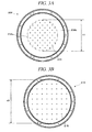
- the gas diffusion plate 206 has a circular first region 206a having a diameter of, e.g., 250 mm and an annular second region 206b at an outside of the first region 206a.
- the through holes 205 are formed in the circular first region 206a at a regular pitch, whereas no through hole 205 is formed in the annular second region 206b.
- a flow rate of the processing gas supplied from the first region 206a per a unit area is set to be higher than a flow rate (zero (0) in the present example embodiment) of the processing gas supplied from the second region 206b per a unit area.
- FIG. 3A an imaginary line indicating a boundary between the first region 206a and the second region 206b is shown by a dashed dotted line.
- FIG. 3B depicts a gas diffusion plate 216 having through holes 215 formed at a regular pitch in the entire surface thereof without separating a first region and a second region.
- the number of the through holes 205 in the gas diffusion plate 206 of FIG. 3A and the number of the through holes 215 in the gas diffusion plate 216 of FIG. 3B are same.
- the through holes 205 are formed at a pitch of, e.g., 28 mm, and the through holes 215 are formed at a pitch of, e.g., 40 mm.
- a diameter d2 of a region of the gas diffusion plate 216 in which the through holes 215 are arranged is set be to be, e.g., 345 mm, larger than the diameter of the semiconductor wafer W.
- the diameter d1 of the first region 206a and the diameter d2 of the region in which the through holes 215 are arranged indicate minimum diameters of circles drawn to include all the through holes 205 and all the through holes 215 therein, respectively.
- the number of the through holes 205, the number of the through holes 215, the pitches between the through holes 205 and the pitches between the through holes 215 are not actual values, and illustration of some of them are omitted.
- a back pressure of the gas diffusion plates 206 and 216 may be, e.g., 13.3 KPa (100 Torr).
- an internal pressure of the processing chamber 201 in which the semiconductor wafer W is placed may be, e.g., 665 Pa (5 Torr).
- the processing gas may be discharged at a substantially uniform flow rate from the through holes 205 and 215 regardless of whether the through holes 205 and 215 are arranged at the central portion or the peripheral portion in the surface of the gas diffusion plates 206 and 216.
- a gas exhaust pipe 207 is provided at a bottom portion of the processing chamber 201.
- the gas exhaust pipe 207 is connected to a non-illustrated vacuum pump or the like, and is configured to evacuate the processing chamber 201 to a preset pressure.
- a deposit removing process is performed as follows.
- an etching process is performed in a pretreatment (block 301), and a reaction product generated by the etching process is deposited on a sidewall portion of a pattern formed on a semiconductor wafer.
- a reaction product generated by the etching process is deposited on a sidewall portion of a pattern formed on a semiconductor wafer.
- a STI Shallow Trench Isolation
- a deposit of silicon oxide e.g., SiO 2 or SiOBr
- the deposit deposited on the sidewall portion of the pattern is removed through the deposit removing process in accordance with the present example embodiment.
- the aforementioned etching process (block 301) is performed by two processes as specified below.
- an oxygen plasma process in the deposit removing process is performed (block 302).
- the oxygen plasma process may be performed in the plasma processing apparatus 100 shown in FIG. 1 or the like.
- the deposit removing process may be performed immediately after the completion of the etching process or after a certain time (e.g., several hours to several days) has been elapsed.
- the oxygen plasma process in the plasma processing apparatus 100 may be performed as follows, for example. That is, in the oxygen plasma process, a semiconductor wafer W is mounted on the stage 102 which is set to have a preset temperature previously. Then, by being attracted to and held by a non-illustrated electrostatic chuck or the like, the semiconductor wafer W is heated to a preset temperature. In this state, a processing gas containing an oxygen gas is introduced through the gas inlet line 105, and the processing chamber is evacuated through the gas exhaust pipe 107, so that an inside of the processing chamber 101 is turned into the processing gas atmosphere of a preset pressure. Then, as a high frequency power is applied to the RF coil 104, inductively coupled plasma of the oxygen gas is generated.
- Ions in this plasma are shielded by the gas diffusion plates 106, and oxygen radicals without having electric charges are supplied to the semiconductor wafer W on the stage 102 in a dispersed state. As a result, the oxygen plasma process with the oxygen radicals is performed.
- This oxygen plasma process is performed to obtain constant moisture absorption states of the pattern and the deposit (i.e., to dehydrate the pattern and the deposit) regardless of the length of the exposure time after the etching process. Accordingly, influence from the different moisture absorption states between the pattern and the deposit can be avoided in a subsequent cycle process. Thus, it is possible to remove the silicon oxide (e.g., SiO 2 or SiOBr), which is the deposit deposited on the sidewall portion of the pattern. Further, it is possible to suppress a SiO 2 layer of a gate oxide film or the like, which is a pattern structure, from being damaged due to the excessive reaction.
- SiO 2 or SiOBr silicon oxide
- an oxygen-containing gas such as, but not limited to, an oxygen single gas or a mixture gas of an oxygen gas and a nitrogen gas may be used as the processing gas.
- a heating temperature of the semiconductor wafer W i.e., stage temperature
- the pressure may be set to be in the range from, e.g., 66.5 Pa (0.5 Torr) to 266 Pa (2 Torr).
- the cycle process in the deposit removing process is performed (blocks 303 to 305). This cycle process may be performed in the gas processing apparatus 200 depicted in FIG. 2 .
- the cycle process in the gas processing apparatus 200 is performed as follows. That is, in the cycle process, the semiconductor wafer W is mounted on the stage 202 which is set to have a preset temperature previously, so that the semiconductor wafer W is maintained at a preset temperature. In this state, a certain processing gas (in this example embodiment, a HF gas + a methanol gas) is introduced through the gas inlet line 203, and the processing chamber is evacuated through the gas exhaust pipe 207, so that the inside of the processing chamber 201 is turned into the processing gas atmosphere of the preset pressure.
- a certain processing gas in this example embodiment, a HF gas + a methanol gas
- a first period during which a partial pressure of the methanol gas is set to be a first partial pressure (block 303) and a second period during which the partial pressure of the methanol gas is set to be a second partial pressure lower than the first partial pressure by evacuating the inside of the processing chamber (block 304) are repeated multiple cycles (block 305).
- the following methods may be utilized, for example.
- a method of varying a gas supply may be used. For example, during the first period, a mixture gas of a preset flow rate is supplied, and then, during the second period, the supply of the mixture gas is stopped and a nitrogen gas of a certain flow rate is supplied.
- a method of varying a pressure may be used. For example, during the first period, while supplying the mixture gas of a preset flow rate, the inside of the processing chamber is maintained at a preset pressure by an automatic pressure controller (APC). Then, during the second period, by lowering a set pressure of the APC or by fully opening the APC, the entire processing chamber is evacuated by a vacuum pump, so that the pressure within the processing chamber is lowered.
- the first period and the second period are set by using the method of the latter.
- the temperature of the semiconductor wafer W may be set to a low temperature equal to or less than, e.g., several tens of degrees ( e.g., 30°C or less).
- the pressure in the first period may be set to be in the range from, e.g., 665 Pa (5 Torr) to 1330 Pa (10 Torr), and a mixture gas of a HF gas and an alcohol gas (a CH 3 OH gas in the present example embodiment) may be used as the processing gas.
- a pressure of the mixture gas or a partial pressure of the alcohol gas is set such that a deposit can be removed by the action of the mixture gas.
- the pressure of the mixture gas or the partial pressure of the alcohol gas is decreased so that the deposit is not removed but substances (H 2 O, etc.) generated by a reaction between the deposit and the mixture gas during the first period is exhausted out of the processing chamber 201.
- the first period and the second period may be set to range from, e.g., 5 seconds to 20 seconds, respectively, and are repeated multiple cycles.
- the constant moisture absorption states of the pattern and the deposit are obtained through the oxygen plasma process regardless of the length of the exposure time after the etching process.
- the gas diffusion plate 206 of the gas processing apparatus 200 has the through holes 205 formed at the uniform pitch in the circular first region 206a having a diameter of 250 mm, whereas no through hole 205 is formed in the annular second region 206b at the outside of the first region 206a, as shown in FIG. 3A .
- a flow rate of the processing gas supplied from the first region 206a per a unit area is set to be higher than a flow rate of the processing gas supplied from the second region 206b per a unit area. Accordingly, it is possible to perform the deposit removal process more uniformly in the entire surface of the semiconductor wafer W.
- a deposit removing rate at a central portion of the semiconductor wafer W may become increased, and a deposit removing rate at a peripheral portion of the semiconductor wafer W becomes decreased. That is, a processing rate in the entire surface of the semiconductor wafer W may become non-uniform. This phenomenon occurs when a pattern is formed on the semiconductor wafer W. When etching a so-called beta film without having a pattern formed on a semiconductor wafer W, an etching rate at a peripheral portion of the semiconductor wafer W may become higher than an etching rate at a central portion thereof.
- the reason why the reverse phenomena take place in the respective cases where the pattern is formed on the semiconductor wafer W and the pattern is not formed on the semiconductor wafer W is deemed to be as follows. That is, a gas velocity above the central portion of the semiconductor wafer W is lower than a gas velocity above an edge portion thereof, and H 2 O, which is generated as a result of the reaction, may not be efficiently exhausted from an inside of the pattern but may stay within the pattern. As a result, the reaction may progress through a catalytic reaction by the H 2 O.
- no through hole 205 is formed in the second region 206b at the outside of the first region 206a.
- the supply amount of the processing gas from the first region 206a per a unit area may be set to be larger than the supply amount of the processing gas from the second region 206b per a unit area.
- the diameter d1 of the first region 206a needs to be set to be smaller than the diameter of the semiconductor wafer W. Desirably, the diameter d1 may be set to range from 70% to 90% of the diameter of the semiconductor wafer W inclusive, and, more desirably, 75% to 85% inclusive.
- the outer diameter of the second region 206b may be set to be larger than the diameter of the semiconductor wafer W.
- a deposit removing process is performed on a semiconductor wafer W left for 1 month after forming a pattern thereon by the etching.
- the oxygen plasma process is performed under the following processing conditions.
- the cycle process is performed under the processing conditions as follows.
- a state in which the set pressure of the APC is set to be 931 Pa (7 Torr) is maintained for 10 seconds during the first period, and, a state in which the APC is fully opened while supplying the processing gas is maintained for 10 seconds during the second period.
- An actual pressure variation in the processing chamber 201 is as shown in a graph of FIG. 5 . That is, even if the set pressure of the APC is set to be 931 Pa (7 Torr) from the state in which the APC is fully opened, it takes 4 seconds to 5 seconds until the pressure actually reaches 931 Pa (7 Torr). Meanwhile, if the APC is fully opened from the state in which the set pressure of the APC is 931 Pa (7 Torr), the pressure may maintain at a constant level of 173 Pa (1.3 Torr) in a relatively short period of time.
- the pressure at which the deposit can be removed (the deposit is peeled off) is 665 Pa (5 Torr). Accordingly, the time corresponding to the 1/2 cycle in the cycle process may be set to range from, e.g., 5 seconds to 20 seconds, desirably. Further, the first period and the second period are not necessarily the same but may be different from each other.
- the semiconductor wafer after the above-described deposit removing process is observed while enlarged by a SEM.
- the deposit deposited on the sidewall portion of the pattern is found to be removed, and no damage on the SiO 2 layer of the pattern structure such as the gate oxide film is observed.
- the same gas process as the experimental example 1 is performed by using a HF single gas after the oxygen plasma process in the first example embodiment, and the deposit is hardly removed.
- the deposit of the sample is removed by setting the pressure to, e.g., 665 Pa (5 Torr), 1330 Pa (10 Torr) and 1995 Pa (15 Torr), respectively.
- 665 Pa 5 Torr
- 1330 Pa 10 Torr
- 1995 Pa 15 Torr
- the deposit of the sample is removed by setting the temperature to 10°C, 30°C and 50°C, respectively.
- the peeling force for the deposit is increased as the temperature decreases.
- the gas process is continually performed without performing the cycle process, the gate oxide film which is the pattern structure is etched and damaged.
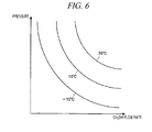
- a boundary line for each of the processing temperatures, between a region in which the deposit removal progresses and a region in which the deposit removal does not progress, as depicted in a graph of FIG. 6 in which a vertical axis represents a pressure and a horizontal axis indicate a flow rate of a methanol gas. If a processing condition (either one of or both of a total pressure and the flow rate of the methanol gas) is changed to pass the boundary line, it is possible to set the first period during which the deposit is removed and the second period during which the deposit is not removed in the cycle process.
- a processing condition either one of or both of a total pressure and the flow rate of the methanol gas
- the above-described deposit removing process is performed on a semiconductor wafer W, in which a line and space pattern is formed and a deposit is deposited in spaces between the lines, by using the gas processing apparatus 200 equipped having the gas diffusion plate 206 shown in FIG. 3A . Then, depths of the spaces between the lines are measured. The depths of the spaces are measured at a central portion and an intermediate portion of the semiconductor wafer W, and at positions of 30 mm and 4 mm away from an edge of the semiconductor wafer W, respectively. As a result, the depths are measured as follows:
- the above-described deposit removing process is performed on a semiconductor wafer W, in which a line and space pattern is formed and a deposit is deposited in spaces between the lines, by using the gas processing apparatus 200 having the gas diffusion plate 216 shown in FIG. 3 B. Then, depths of the spaces between the lines are measured.
- the deposit removing process is performed under the same conditions as those of the experimental example 2, excepting that the gas diffusion plate 216 is used. The depths of the spaces are measured at a central portion and an intermediate portion of the semiconductor wafer W, and at positions of 30 mm and 4 mm away from an edge of the semiconductor wafer W, respectively. As a result, the depths are measured as follows:
- the example embodiment may be applicable to the field of manufacture of semiconductor devices, and, thus, has industrial applicability.
Landscapes
- Engineering & Computer Science (AREA)
- Physics & Mathematics (AREA)
- Condensed Matter Physics & Semiconductors (AREA)
- General Physics & Mathematics (AREA)
- Manufacturing & Machinery (AREA)
- Computer Hardware Design (AREA)
- Microelectronics & Electronic Packaging (AREA)
- Power Engineering (AREA)
- Plasma & Fusion (AREA)
- Chemical & Material Sciences (AREA)
- Analytical Chemistry (AREA)
- Drying Of Semiconductors (AREA)
Applications Claiming Priority (3)
| Application Number | Priority Date | Filing Date | Title |
|---|---|---|---|
| JP2012094439A JP6017170B2 (ja) | 2012-04-18 | 2012-04-18 | 堆積物除去方法及びガス処理装置 |
| US201261637385P | 2012-04-24 | 2012-04-24 | |
| EP13778233.0 | 2013-04-12 |
Related Parent Applications (1)
| Application Number | Title | Priority Date | Filing Date |
|---|---|---|---|
| EP13778233.0 Division | 2012-04-18 | 2013-04-12 |
Publications (3)
| Publication Number | Publication Date |
|---|---|
| EP2819150A2 true EP2819150A2 (de) | 2014-12-31 |
| EP2819150A3 EP2819150A3 (de) | 2015-03-18 |
| EP2819150B1 EP2819150B1 (de) | 2017-09-27 |
Family
ID=49383207
Family Applications (1)
| Application Number | Title | Priority Date | Filing Date |
|---|---|---|---|
| EP14185469.5A Active EP2819150B1 (de) | 2012-04-18 | 2013-04-12 | Ablagerungsbeseitigungsverfahren |
Country Status (6)
| Country | Link |
|---|---|
| US (1) | US20150064925A1 (de) |
| EP (1) | EP2819150B1 (de) |
| JP (1) | JP6017170B2 (de) |
| KR (1) | KR102108111B1 (de) |
| CN (1) | CN104505333B (de) |
| WO (1) | WO2013157235A1 (de) |
Cited By (1)
| Publication number | Priority date | Publication date | Assignee | Title |
|---|---|---|---|---|
| WO2017121704A1 (de) | 2016-01-15 | 2017-07-20 | Aixtron Se | Vorrichtung zum bereitstellen eines prozessgases in einer beschichtungseinrichtung |
Families Citing this family (2)
| Publication number | Priority date | Publication date | Assignee | Title |
|---|---|---|---|---|
| JP2016025195A (ja) * | 2014-07-18 | 2016-02-08 | 東京エレクトロン株式会社 | エッチング方法 |
| JP6499001B2 (ja) | 2015-04-20 | 2019-04-10 | 東京エレクトロン株式会社 | 多孔質膜をエッチングする方法 |
Citations (1)
| Publication number | Priority date | Publication date | Assignee | Title |
|---|---|---|---|---|
| JPH07263416A (ja) | 1994-03-18 | 1995-10-13 | Fujitsu Ltd | 半導体装置の製造方法と製造装置 |
Family Cites Families (22)
| Publication number | Priority date | Publication date | Assignee | Title |
|---|---|---|---|---|
| US5580421A (en) * | 1994-06-14 | 1996-12-03 | Fsi International | Apparatus for surface conditioning |
| US5922219A (en) * | 1996-10-31 | 1999-07-13 | Fsi International, Inc. | UV/halogen treatment for dry oxide etching |
| JPH11279778A (ja) * | 1998-03-30 | 1999-10-12 | Seiko Epson Corp | エッチング装置及び半導体装置の製造方法 |
| JP2000357680A (ja) * | 1999-06-15 | 2000-12-26 | Nec Kyushu Ltd | シリコン系プラズマエッチングに於ける酸素プラズマ照射によるアウトガス防止方法 |
| US6284666B1 (en) * | 2000-05-31 | 2001-09-04 | International Business Machines Corporation | Method of reducing RIE lag for deep trench silicon etching |
| JP2002353205A (ja) * | 2000-08-28 | 2002-12-06 | Mitsubishi Electric Corp | 半導体装置の製造方法およびそれに用いられるウェハ処理装置並びに半導体装置 |
| US6333272B1 (en) * | 2000-10-06 | 2001-12-25 | Lam Research Corporation | Gas distribution apparatus for semiconductor processing |
| US6846746B2 (en) * | 2002-05-01 | 2005-01-25 | Applied Materials, Inc. | Method of smoothing a trench sidewall after a deep trench silicon etch process |
| TW587139B (en) * | 2002-10-18 | 2004-05-11 | Winbond Electronics Corp | Gas distribution system and method for the plasma gas in the chamber |
| US6936193B2 (en) * | 2003-04-14 | 2005-08-30 | Research Frontiers Incorporated | Suspended particle device light valve film |
| KR100526928B1 (ko) * | 2003-07-16 | 2005-11-09 | 삼성전자주식회사 | 식각장치 |
| JP2006156122A (ja) * | 2004-11-29 | 2006-06-15 | Sekisui Chem Co Ltd | プラズマ処理装置 |
| WO2008088300A2 (en) * | 2005-03-08 | 2008-07-24 | Primaxx, Inc. | Selective etching of oxides from substrates |
| GB0615343D0 (en) * | 2006-08-02 | 2006-09-13 | Point 35 Microstructures Ltd | Improved etch process |
| JP4661753B2 (ja) * | 2006-09-29 | 2011-03-30 | 東京エレクトロン株式会社 | 基板処理方法、洗浄方法及び記憶媒体 |
| JP4849614B2 (ja) * | 2006-11-01 | 2012-01-11 | 東京エレクトロン株式会社 | 基板処理方法及び基板処理システム |
| CN100527361C (zh) * | 2006-12-06 | 2009-08-12 | 北京北方微电子基地设备工艺研究中心有限责任公司 | 气体分布装置 |
| JP2008186865A (ja) * | 2007-01-26 | 2008-08-14 | Tokyo Electron Ltd | 基板処理装置 |
| US7988813B2 (en) * | 2007-03-12 | 2011-08-02 | Tokyo Electron Limited | Dynamic control of process chemistry for improved within-substrate process uniformity |
| US20100025370A1 (en) * | 2008-08-04 | 2010-02-04 | Applied Materials, Inc. | Reactive gas distributor, reactive gas treatment system, and reactive gas treatment method |
| JP5823160B2 (ja) * | 2011-05-11 | 2015-11-25 | 東京エレクトロン株式会社 | 堆積物除去方法 |
| JP5859262B2 (ja) * | 2011-09-29 | 2016-02-10 | 東京エレクトロン株式会社 | 堆積物除去方法 |
-
2012
- 2012-04-18 JP JP2012094439A patent/JP6017170B2/ja active Active
-
2013
- 2013-04-12 KR KR1020147034719A patent/KR102108111B1/ko active IP Right Grant
- 2013-04-12 EP EP14185469.5A patent/EP2819150B1/de active Active
- 2013-04-12 CN CN201410614517.XA patent/CN104505333B/zh active Active
- 2013-04-12 WO PCT/JP2013/002509 patent/WO2013157235A1/ja unknown
-
2014
- 2014-09-17 US US14/488,575 patent/US20150064925A1/en not_active Abandoned
Patent Citations (1)
| Publication number | Priority date | Publication date | Assignee | Title |
|---|---|---|---|---|
| JPH07263416A (ja) | 1994-03-18 | 1995-10-13 | Fujitsu Ltd | 半導体装置の製造方法と製造装置 |
Cited By (2)
| Publication number | Priority date | Publication date | Assignee | Title |
|---|---|---|---|---|
| WO2017121704A1 (de) | 2016-01-15 | 2017-07-20 | Aixtron Se | Vorrichtung zum bereitstellen eines prozessgases in einer beschichtungseinrichtung |
| DE102016100625A1 (de) | 2016-01-15 | 2017-07-20 | Aixtron Se | Vorrichtung zum Bereitstellen eines Prozessgases in einer Beschichtungseinrichtung |
Also Published As
| Publication number | Publication date |
|---|---|
| KR20150010779A (ko) | 2015-01-28 |
| CN104505333B (zh) | 2017-05-10 |
| KR102108111B1 (ko) | 2020-05-08 |
| US20150064925A1 (en) | 2015-03-05 |
| JP2013222875A (ja) | 2013-10-28 |
| CN104505333A (zh) | 2015-04-08 |
| EP2819150B1 (de) | 2017-09-27 |
| EP2819150A3 (de) | 2015-03-18 |
| WO2013157235A1 (ja) | 2013-10-24 |
| JP6017170B2 (ja) | 2016-10-26 |
Similar Documents
| Publication | Publication Date | Title |
|---|---|---|
| JP5823160B2 (ja) | 堆積物除去方法 | |
| US8945414B1 (en) | Oxide removal by remote plasma treatment with fluorine and oxygen radicals | |
| KR101930577B1 (ko) | 퇴적물 제거 방법 | |
| US11183393B2 (en) | Atomic layer etching using acid halide | |
| KR20170018817A (ko) | 기판 처리 시스템 및 기판 처리 방법 | |
| KR101276262B1 (ko) | 반도체 제조 장치 및 반도체 제조 방법 | |
| JP7401593B2 (ja) | 空隙を形成するためのシステム及び方法 | |
| EP2819150B1 (de) | Ablagerungsbeseitigungsverfahren | |
| JP4184851B2 (ja) | プラズマ処理方法 | |
| US10755941B2 (en) | Self-limiting selective etching systems and methods | |
| JP2008186991A (ja) | エッチング方法及びエッチング装置 | |
| JP2005086080A (ja) | 半導体装置の製造方法 |
Legal Events
| Date | Code | Title | Description |
|---|---|---|---|
| PUAI | Public reference made under article 153(3) epc to a published international application that has entered the european phase |
Free format text: ORIGINAL CODE: 0009012 |
|
| 17P | Request for examination filed |
Effective date: 20141104 |
|
| AK | Designated contracting states |
Kind code of ref document: A2 Designated state(s): AL AT BE BG CH CY CZ DE DK EE ES FI FR GB GR HR HU IE IS IT LI LT LU LV MC MK MT NL NO PL PT RO RS SE SI SK SM TR |
|
| AX | Request for extension of the european patent |
Extension state: BA ME |
|
| PUAL | Search report despatched |
Free format text: ORIGINAL CODE: 0009013 |
|
| AK | Designated contracting states |
Kind code of ref document: A3 Designated state(s): AL AT BE BG CH CY CZ DE DK EE ES FI FR GB GR HR HU IE IS IT LI LT LU LV MC MK MT NL NO PL PT RO RS SE SI SK SM TR |
|
| AX | Request for extension of the european patent |
Extension state: BA ME |
|
| RIC1 | Information provided on ipc code assigned before grant |
Ipc: H01L 21/67 20060101ALI20150209BHEP Ipc: H01L 21/306 20060101AFI20150209BHEP |
|
| GRAP | Despatch of communication of intention to grant a patent |
Free format text: ORIGINAL CODE: EPIDOSNIGR1 |
|
| INTG | Intention to grant announced |
Effective date: 20170411 |
|
| GRAS | Grant fee paid |
Free format text: ORIGINAL CODE: EPIDOSNIGR3 |
|
| GRAA | (expected) grant |
Free format text: ORIGINAL CODE: 0009210 |
|
| AK | Designated contracting states |
Kind code of ref document: B1 Designated state(s): AL AT BE BG CH CY CZ DE DK EE ES FI FR GB GR HR HU IE IS IT LI LT LU LV MC MK MT NL NO PL PT RO RS SE SI SK SM TR |
|
| REG | Reference to a national code |
Ref country code: GB Ref legal event code: FG4D |
|
| REG | Reference to a national code |
Ref country code: CH Ref legal event code: EP |
|
| REG | Reference to a national code |
Ref country code: AT Ref legal event code: REF Ref document number: 932729 Country of ref document: AT Kind code of ref document: T Effective date: 20171015 |
|
| REG | Reference to a national code |
Ref country code: IE Ref legal event code: FG4D |
|
| REG | Reference to a national code |
Ref country code: DE Ref legal event code: R096 Ref document number: 602013027353 Country of ref document: DE |
|
| PG25 | Lapsed in a contracting state [announced via postgrant information from national office to epo] |
Ref country code: FI Free format text: LAPSE BECAUSE OF FAILURE TO SUBMIT A TRANSLATION OF THE DESCRIPTION OR TO PAY THE FEE WITHIN THE PRESCRIBED TIME-LIMIT Effective date: 20170927 Ref country code: LT Free format text: LAPSE BECAUSE OF FAILURE TO SUBMIT A TRANSLATION OF THE DESCRIPTION OR TO PAY THE FEE WITHIN THE PRESCRIBED TIME-LIMIT Effective date: 20170927 Ref country code: NO Free format text: LAPSE BECAUSE OF FAILURE TO SUBMIT A TRANSLATION OF THE DESCRIPTION OR TO PAY THE FEE WITHIN THE PRESCRIBED TIME-LIMIT Effective date: 20171227 Ref country code: SE Free format text: LAPSE BECAUSE OF FAILURE TO SUBMIT A TRANSLATION OF THE DESCRIPTION OR TO PAY THE FEE WITHIN THE PRESCRIBED TIME-LIMIT Effective date: 20170927 Ref country code: HR Free format text: LAPSE BECAUSE OF FAILURE TO SUBMIT A TRANSLATION OF THE DESCRIPTION OR TO PAY THE FEE WITHIN THE PRESCRIBED TIME-LIMIT Effective date: 20170927 |
|
| REG | Reference to a national code |
Ref country code: NL Ref legal event code: MP Effective date: 20170927 |
|
| REG | Reference to a national code |
Ref country code: LT Ref legal event code: MG4D |
|
| REG | Reference to a national code |
Ref country code: AT Ref legal event code: MK05 Ref document number: 932729 Country of ref document: AT Kind code of ref document: T Effective date: 20170927 |
|
| PG25 | Lapsed in a contracting state [announced via postgrant information from national office to epo] |
Ref country code: LV Free format text: LAPSE BECAUSE OF FAILURE TO SUBMIT A TRANSLATION OF THE DESCRIPTION OR TO PAY THE FEE WITHIN THE PRESCRIBED TIME-LIMIT Effective date: 20170927 Ref country code: RS Free format text: LAPSE BECAUSE OF FAILURE TO SUBMIT A TRANSLATION OF THE DESCRIPTION OR TO PAY THE FEE WITHIN THE PRESCRIBED TIME-LIMIT Effective date: 20170927 Ref country code: BG Free format text: LAPSE BECAUSE OF FAILURE TO SUBMIT A TRANSLATION OF THE DESCRIPTION OR TO PAY THE FEE WITHIN THE PRESCRIBED TIME-LIMIT Effective date: 20171227 Ref country code: GR Free format text: LAPSE BECAUSE OF FAILURE TO SUBMIT A TRANSLATION OF THE DESCRIPTION OR TO PAY THE FEE WITHIN THE PRESCRIBED TIME-LIMIT Effective date: 20171228 |
|
| PG25 | Lapsed in a contracting state [announced via postgrant information from national office to epo] |
Ref country code: NL Free format text: LAPSE BECAUSE OF FAILURE TO SUBMIT A TRANSLATION OF THE DESCRIPTION OR TO PAY THE FEE WITHIN THE PRESCRIBED TIME-LIMIT Effective date: 20170927 |
|
| PG25 | Lapsed in a contracting state [announced via postgrant information from national office to epo] |
Ref country code: CZ Free format text: LAPSE BECAUSE OF FAILURE TO SUBMIT A TRANSLATION OF THE DESCRIPTION OR TO PAY THE FEE WITHIN THE PRESCRIBED TIME-LIMIT Effective date: 20170927 Ref country code: ES Free format text: LAPSE BECAUSE OF FAILURE TO SUBMIT A TRANSLATION OF THE DESCRIPTION OR TO PAY THE FEE WITHIN THE PRESCRIBED TIME-LIMIT Effective date: 20170927 |
|
| PG25 | Lapsed in a contracting state [announced via postgrant information from national office to epo] |
Ref country code: IT Free format text: LAPSE BECAUSE OF FAILURE TO SUBMIT A TRANSLATION OF THE DESCRIPTION OR TO PAY THE FEE WITHIN THE PRESCRIBED TIME-LIMIT Effective date: 20170927 Ref country code: SK Free format text: LAPSE BECAUSE OF FAILURE TO SUBMIT A TRANSLATION OF THE DESCRIPTION OR TO PAY THE FEE WITHIN THE PRESCRIBED TIME-LIMIT Effective date: 20170927 Ref country code: IS Free format text: LAPSE BECAUSE OF FAILURE TO SUBMIT A TRANSLATION OF THE DESCRIPTION OR TO PAY THE FEE WITHIN THE PRESCRIBED TIME-LIMIT Effective date: 20180127 Ref country code: EE Free format text: LAPSE BECAUSE OF FAILURE TO SUBMIT A TRANSLATION OF THE DESCRIPTION OR TO PAY THE FEE WITHIN THE PRESCRIBED TIME-LIMIT Effective date: 20170927 Ref country code: AT Free format text: LAPSE BECAUSE OF FAILURE TO SUBMIT A TRANSLATION OF THE DESCRIPTION OR TO PAY THE FEE WITHIN THE PRESCRIBED TIME-LIMIT Effective date: 20170927 Ref country code: SM Free format text: LAPSE BECAUSE OF FAILURE TO SUBMIT A TRANSLATION OF THE DESCRIPTION OR TO PAY THE FEE WITHIN THE PRESCRIBED TIME-LIMIT Effective date: 20170927 |
|
| REG | Reference to a national code |
Ref country code: DE Ref legal event code: R097 Ref document number: 602013027353 Country of ref document: DE |
|
| PG25 | Lapsed in a contracting state [announced via postgrant information from national office to epo] |
Ref country code: DK Free format text: LAPSE BECAUSE OF FAILURE TO SUBMIT A TRANSLATION OF THE DESCRIPTION OR TO PAY THE FEE WITHIN THE PRESCRIBED TIME-LIMIT Effective date: 20170927 |
|
| PLBE | No opposition filed within time limit |
Free format text: ORIGINAL CODE: 0009261 |
|
| STAA | Information on the status of an ep patent application or granted ep patent |
Free format text: STATUS: NO OPPOSITION FILED WITHIN TIME LIMIT |
|
| PG25 | Lapsed in a contracting state [announced via postgrant information from national office to epo] |
Ref country code: PL Free format text: LAPSE BECAUSE OF FAILURE TO SUBMIT A TRANSLATION OF THE DESCRIPTION OR TO PAY THE FEE WITHIN THE PRESCRIBED TIME-LIMIT Effective date: 20170927 |
|
| 26N | No opposition filed |
Effective date: 20180628 |
|
| PG25 | Lapsed in a contracting state [announced via postgrant information from national office to epo] |
Ref country code: MC Free format text: LAPSE BECAUSE OF FAILURE TO SUBMIT A TRANSLATION OF THE DESCRIPTION OR TO PAY THE FEE WITHIN THE PRESCRIBED TIME-LIMIT Effective date: 20170927 Ref country code: SI Free format text: LAPSE BECAUSE OF FAILURE TO SUBMIT A TRANSLATION OF THE DESCRIPTION OR TO PAY THE FEE WITHIN THE PRESCRIBED TIME-LIMIT Effective date: 20170927 |
|
| REG | Reference to a national code |
Ref country code: CH Ref legal event code: PL |
|
| REG | Reference to a national code |
Ref country code: BE Ref legal event code: MM Effective date: 20180430 |
|
| GBPC | Gb: european patent ceased through non-payment of renewal fee |
Effective date: 20180412 |
|
| REG | Reference to a national code |
Ref country code: IE Ref legal event code: MM4A |
|
| PG25 | Lapsed in a contracting state [announced via postgrant information from national office to epo] |
Ref country code: LU Free format text: LAPSE BECAUSE OF NON-PAYMENT OF DUE FEES Effective date: 20180412 |
|
| PG25 | Lapsed in a contracting state [announced via postgrant information from national office to epo] |
Ref country code: LI Free format text: LAPSE BECAUSE OF NON-PAYMENT OF DUE FEES Effective date: 20180430 Ref country code: CH Free format text: LAPSE BECAUSE OF NON-PAYMENT OF DUE FEES Effective date: 20180430 Ref country code: GB Free format text: LAPSE BECAUSE OF NON-PAYMENT OF DUE FEES Effective date: 20180412 Ref country code: BE Free format text: LAPSE BECAUSE OF NON-PAYMENT OF DUE FEES Effective date: 20180430 |
|
| PG25 | Lapsed in a contracting state [announced via postgrant information from national office to epo] |
Ref country code: IE Free format text: LAPSE BECAUSE OF NON-PAYMENT OF DUE FEES Effective date: 20180412 Ref country code: FR Free format text: LAPSE BECAUSE OF NON-PAYMENT OF DUE FEES Effective date: 20180430 |
|
| PG25 | Lapsed in a contracting state [announced via postgrant information from national office to epo] |
Ref country code: MT Free format text: LAPSE BECAUSE OF NON-PAYMENT OF DUE FEES Effective date: 20180412 |
|
| PG25 | Lapsed in a contracting state [announced via postgrant information from national office to epo] |
Ref country code: TR Free format text: LAPSE BECAUSE OF FAILURE TO SUBMIT A TRANSLATION OF THE DESCRIPTION OR TO PAY THE FEE WITHIN THE PRESCRIBED TIME-LIMIT Effective date: 20170927 |
|
| PG25 | Lapsed in a contracting state [announced via postgrant information from national office to epo] |
Ref country code: PT Free format text: LAPSE BECAUSE OF FAILURE TO SUBMIT A TRANSLATION OF THE DESCRIPTION OR TO PAY THE FEE WITHIN THE PRESCRIBED TIME-LIMIT Effective date: 20170927 Ref country code: HU Free format text: LAPSE BECAUSE OF FAILURE TO SUBMIT A TRANSLATION OF THE DESCRIPTION OR TO PAY THE FEE WITHIN THE PRESCRIBED TIME-LIMIT; INVALID AB INITIO Effective date: 20130412 |
|
| PG25 | Lapsed in a contracting state [announced via postgrant information from national office to epo] |
Ref country code: CY Free format text: LAPSE BECAUSE OF FAILURE TO SUBMIT A TRANSLATION OF THE DESCRIPTION OR TO PAY THE FEE WITHIN THE PRESCRIBED TIME-LIMIT Effective date: 20170927 Ref country code: RO Free format text: LAPSE BECAUSE OF FAILURE TO SUBMIT A TRANSLATION OF THE DESCRIPTION OR TO PAY THE FEE WITHIN THE PRESCRIBED TIME-LIMIT Effective date: 20170927 Ref country code: MK Free format text: LAPSE BECAUSE OF NON-PAYMENT OF DUE FEES Effective date: 20170927 |
|
| PG25 | Lapsed in a contracting state [announced via postgrant information from national office to epo] |
Ref country code: AL Free format text: LAPSE BECAUSE OF FAILURE TO SUBMIT A TRANSLATION OF THE DESCRIPTION OR TO PAY THE FEE WITHIN THE PRESCRIBED TIME-LIMIT Effective date: 20170927 |
|
| PGFP | Annual fee paid to national office [announced via postgrant information from national office to epo] |
Ref country code: DE Payment date: 20230228 Year of fee payment: 11 |