EP2818937B1 - Developing device, process cartridge, and electrophotographic apparatus - Google Patents
Developing device, process cartridge, and electrophotographic apparatus Download PDFInfo
- Publication number
- EP2818937B1 EP2818937B1 EP14001892.0A EP14001892A EP2818937B1 EP 2818937 B1 EP2818937 B1 EP 2818937B1 EP 14001892 A EP14001892 A EP 14001892A EP 2818937 B1 EP2818937 B1 EP 2818937B1
- Authority
- EP
- European Patent Office
- Prior art keywords
- toner
- developing
- developing device
- spherical resin
- resin particles
- Prior art date
- Legal status (The legal status is an assumption and is not a legal conclusion. Google has not performed a legal analysis and makes no representation as to the accuracy of the status listed.)
- Active
Links
Images

Classifications
-
- G—PHYSICS
- G03—PHOTOGRAPHY; CINEMATOGRAPHY; ANALOGOUS TECHNIQUES USING WAVES OTHER THAN OPTICAL WAVES; ELECTROGRAPHY; HOLOGRAPHY
- G03G—ELECTROGRAPHY; ELECTROPHOTOGRAPHY; MAGNETOGRAPHY
- G03G15/00—Apparatus for electrographic processes using a charge pattern
- G03G15/06—Apparatus for electrographic processes using a charge pattern for developing
- G03G15/08—Apparatus for electrographic processes using a charge pattern for developing using a solid developer, e.g. powder developer
- G03G15/0806—Apparatus for electrographic processes using a charge pattern for developing using a solid developer, e.g. powder developer on a donor element, e.g. belt, roller
- G03G15/0812—Apparatus for electrographic processes using a charge pattern for developing using a solid developer, e.g. powder developer on a donor element, e.g. belt, roller characterised by the developer regulating means, e.g. structure of doctor blade
-
- G—PHYSICS
- G03—PHOTOGRAPHY; CINEMATOGRAPHY; ANALOGOUS TECHNIQUES USING WAVES OTHER THAN OPTICAL WAVES; ELECTROGRAPHY; HOLOGRAPHY
- G03G—ELECTROGRAPHY; ELECTROPHOTOGRAPHY; MAGNETOGRAPHY
- G03G15/00—Apparatus for electrographic processes using a charge pattern
- G03G15/06—Apparatus for electrographic processes using a charge pattern for developing
- G03G15/08—Apparatus for electrographic processes using a charge pattern for developing using a solid developer, e.g. powder developer
- G03G15/0806—Apparatus for electrographic processes using a charge pattern for developing using a solid developer, e.g. powder developer on a donor element, e.g. belt, roller
- G03G15/081—Apparatus for electrographic processes using a charge pattern for developing using a solid developer, e.g. powder developer on a donor element, e.g. belt, roller characterised by the developer handling means after the supply and before the regulating, e.g. means for preventing developer blocking
-
- G—PHYSICS
- G03—PHOTOGRAPHY; CINEMATOGRAPHY; ANALOGOUS TECHNIQUES USING WAVES OTHER THAN OPTICAL WAVES; ELECTROGRAPHY; HOLOGRAPHY
- G03G—ELECTROGRAPHY; ELECTROPHOTOGRAPHY; MAGNETOGRAPHY
- G03G15/00—Apparatus for electrographic processes using a charge pattern
- G03G15/06—Apparatus for electrographic processes using a charge pattern for developing
- G03G15/08—Apparatus for electrographic processes using a charge pattern for developing using a solid developer, e.g. powder developer
- G03G15/0806—Apparatus for electrographic processes using a charge pattern for developing using a solid developer, e.g. powder developer on a donor element, e.g. belt, roller
- G03G15/0813—Apparatus for electrographic processes using a charge pattern for developing using a solid developer, e.g. powder developer on a donor element, e.g. belt, roller characterised by means in the developing zone having an interaction with the image carrying member, e.g. distance holders
-
- G—PHYSICS
- G03—PHOTOGRAPHY; CINEMATOGRAPHY; ANALOGOUS TECHNIQUES USING WAVES OTHER THAN OPTICAL WAVES; ELECTROGRAPHY; HOLOGRAPHY
- G03G—ELECTROGRAPHY; ELECTROPHOTOGRAPHY; MAGNETOGRAPHY
- G03G15/00—Apparatus for electrographic processes using a charge pattern
- G03G15/06—Apparatus for electrographic processes using a charge pattern for developing
- G03G15/08—Apparatus for electrographic processes using a charge pattern for developing using a solid developer, e.g. powder developer
- G03G15/0806—Apparatus for electrographic processes using a charge pattern for developing using a solid developer, e.g. powder developer on a donor element, e.g. belt, roller
- G03G15/0818—Apparatus for electrographic processes using a charge pattern for developing using a solid developer, e.g. powder developer on a donor element, e.g. belt, roller characterised by the structure of the donor member, e.g. surface properties
-
- G—PHYSICS
- G03—PHOTOGRAPHY; CINEMATOGRAPHY; ANALOGOUS TECHNIQUES USING WAVES OTHER THAN OPTICAL WAVES; ELECTROGRAPHY; HOLOGRAPHY
- G03G—ELECTROGRAPHY; ELECTROPHOTOGRAPHY; MAGNETOGRAPHY
- G03G15/00—Apparatus for electrographic processes using a charge pattern
- G03G15/06—Apparatus for electrographic processes using a charge pattern for developing
- G03G15/08—Apparatus for electrographic processes using a charge pattern for developing using a solid developer, e.g. powder developer
- G03G15/0896—Arrangements or disposition of the complete developer unit or parts thereof not provided for by groups G03G15/08 - G03G15/0894
Definitions
- the present invention relates to a developing device, a process cartridge, and an electrophotographic apparatus.
- an electrophotographic apparatus such as a copier, a printer, and a receiver of a facsimile
- a rotating image carrying member is uniformly charged by a charging member, and laser light is applied to the charged image carrying member, whereby an electrostatic latent image is formed.
- toner is supplied to the electrostatic latent image by a developing device, whereby the electrostatic latent image is developed into a toner image.
- the toner image is transferred from the image carrying member to a transfer material (a recording material), and the toner image on the transfer material is fixed by heating or the like.
- the transfer material has an image.
- the static electricity on the surface of the image carrying member that has undergone the transfer of the toner image is eliminated, and residual toner is removed from the surface of the image carrying member.
- the electrophotographic apparatus is ready for forming another image.
- the developing device includes a developing chamber and a toner container that contains toner.
- the developing chamber is provided with a developing roller, a toner supplying member that supplies toner to the surface of the developing roller, and so forth.
- the developing chamber is further provided with a toner regulating member that regulates the toner supplied to the surface of the developing roller by the toner supplying member into a thin layer having a more uniform thickness.
- toner remains contained in the toner container.
- the toner starts to be fed into the developing chamber.
- the developing roller is directly in contact with the toner regulating member and the toner supplying member.
- Japanese Patent Laid-Open No. 8-227212 addresses problems such as damage to a toner supplying member attributed to the direct contact between a developing sleeve and the toner supplying member in a developing device that is yet to be used. According to Japanese Patent Laid-Open No. 8-227212 , such a problem is solved by employing a toner supplying member having cells on its outermost layer and by providing powder having specific chargeability at least on the surface of the toner supplying member.
- electrostatic memory Such a change in the surface of the developing roller that affects the quality of resulting electrophotographic images is occasionally referred to as “electrostatic memory.”
- electrostatic memory A phenomenon of the appearance of such an “electrostatic memory” is occasionally referred to as “generation of an electrostatic memory.”
- the present invention is directed to providing a developing device in which an electrostatic memory that may cause banding in electrophotographic images does not tend to be generated on a developing roller even if the developing device that is yet to be used is vibrated during long-time transportation.
- the present invention is also directed to providing an electrophotographic apparatus that is capable of stably outputting high-quality electrophotographic images.
- JP 2009 1 16009 A discloses a conductive roll, comprising an elastic layer formed on a shaft body and an outermost layer formed on the elastic layer, wherein semiconductive particles are dispersed in the outermost layer.
- US 2013/028634 A1 discloses a developing roller having a mandrel, an elastic layer and a surface layer covering the elastic layer surface, wherein the surface layer contains a urethane resin.
- the present invention in its first aspect provides a developing device as specified in claims 1 to 5.
- the present invention in its second aspect provides a process cartridge as specified in claim 6.
- the present invention in its third aspect provides an electrophotographic apparatus as specified in claim 7.
- the present inventors have thoroughly reviewed the developing device disclosed by Japanese Patent Laid-Open No. 2007-33538 , focusing on an electrostatic memory attributed to vibration continuing for a long time, and have found three possible major causes of such an electrostatic memory.
- an uneven distribution of the powder on the surface of the developing roller or the toner regulating member may also generate a thrust memory. More specifically, the powder is initially distributed evenly in the contact portion between the developing roller and the toner regulating member. However, as the developing device is vibrated repeatedly, some particles of the powder may gather, resulting in an uneven distribution of the powder. Consequently, the developing roller and the toner regulating member come into direct contact with each other in some portions, where a thrust memory may be generated.
- the generation of an electrostatic memory may be attributed to some physical stress applied to the developing roller and the toner regulating member from particles that are present in the contact portion between the two. Although details of such a mechanism are unknown, the present inventors presume that a physical stress that is applied over a long time may cause slight nonuniformity in the electric resistance or some other phenomenon on the surface of the developing roller.
- an electrostatic memory may be generated by some physical stress applied to the developing roller.
- the present inventors have considered that the above problem would be solved if particles provided between the developing roller and the toner regulating member show the following behaviour.
- spherical resin particles are provided at least in a contact portion between a developing roller and a toner regulating member. Additionally the Martens hardness of the spherical resin particles is 0.5 N/mm 2 or higher and 45 N/mm 2 or lower, and the restoring elastic power of the spherical resin particles is 70% or higher.
- the Martens hardness of the spherical resin particles are within the range of 0.5 N/mm 2 or higher and 45 N/mm 2 or lower so that the physical stress that may be applied to the developing roller is reduced as much as possible.
- the Martens hardness is higher than 45 N/mm 2 , a thrust memory attributed to a large physical stress to the developing roller may be generated. If the Martens hardness is smaller than 0.5 N/mm 2 , an effect of suppressing the generation of a thrust memory is produced. However, the spherical resin particles become very sticky and may, for example, stick to associated members.
- the restoring elastic power of the spherical resin particles is set to 70% or higher.
- the base material of the spherical resin particles may be urethane resin or silicone resin.
- the spherical resin particles according to the general embodiment of the present invention may have an average circularity of 0.96 or higher. If the spherical resin particles have an average circularity of 0.96 or higher, the probability that the spherical resin particles are prevented from rolling is low, which is considered to be especially effective for suppressing the generation of a thrust memory.
- the weight-average particle size of the spherical resin particles may be 1 ⁇ m or larger and 50 ⁇ m or smaller.
- the Martens hardness and the restoring elastic power of the spherical resin particles are measured by using a microhardness measuring instrument (PICODENTOR (a registered trademark) HM500 manufactured by Fischer Instruments K.K.) with a regular-pyramid diamond indenter (Vickers indenter) whose angle between opposite faces is 136°.
- PICODENTOR a registered trademark
- HM500 regular-pyramid diamond indenter
- the measurement includes a step of pressing the indenter into a particle with a predetermined load (the step is hereinafter referred to as indenting step), and a step of removing the predetermined load (the step is hereinafter referred to as unloading step).
- a load displacement curve obtained in the measurement is evaluated by using exclusive measurement software "WIN-HCU (a registered trademark)."
- WIN-HCU exclusive measurement software
- the Martens hardness (N/mm 2 ) and the restoring elastic power (We/Wt ⁇ 100, where We denotes the restoring workload of elastic deformation caused by indentation, and Wt denotes the total workload of mechanical indentation) are obtained.
- a specific measurement procedure is as follows. Spherical resin particles are provided on a slide glass (manufactured by AS ONE Corporation) with a cotton swab, excessive spherical resin particles are blown off with air, and the remaining spherical resin particles are measured.
- the spherical resin particles to be measured are selected from those each having a size that is as approximate as possible to the below-described weight-average particle size (D4).
- the measurement stage Since the measurement stage has a resolution of 1 ⁇ m, it is difficult to press the tip of the indenter into the center of a small spherical resin particle having a size of about 10 ⁇ m. Therefore, the indenter may be pressed into a sloping portion of the spherical resin particle, failing in correct measurement. Moreover, if the centroid of the spherical resin particle is changed, the spherical resin particle may be displaced during the measurement, failing in correct measurement. To avoid such phenomena, after the indenter is pressed into a spherical resin particle, the stage is moved to a microscope and whether or not the spherical resin particle is displaced from the position taken before the indentation with the indenter is checked.
- the tip of the indenter is regarded as being in contact with the center of the spherical resin particle.
- data obtained in the measurement is regarded as being correct and effective and is used for the calculations of the Martens hardness and the restoring elastic power.
- the indenter may be adjusted for each measurement. Furthermore, the indenter may be cleaned with ethanol for each measurement.
- Measurement conditions for the indenting step and the unloading step are set as follows.
- Indenting step An indenting load is applied to the spherical resin particle for an indenting time of 20 seconds while the indenting load is increased from 0 mN to 0.1 mN with a constant increment per unit time.
- Unloading step The indenting load on the spherical resin particle is reduced over an unloading time of 20 seconds from 0.1 mN to 0 mN with a constant decrement per unit time.
- the average of 18 pieces of effective data which are those excluding the maximum value and the minimum value, is calculated and taken as the Martens hardness and the restoring elastic power of the spherical resin particles according to the general embodiment of the present invention.
- the average circularity of the spherical resin particles is measured by using a flow-type particle image analyzer "FPIA-3000" (manufactured by Sysmex Corporation) under measurement and analysis conditions set forth at the time of calibration work.
- FPIA-3000 flow-type particle image analyzer
- ion-exchanged water from which impure solid matter and the like have been removed in advance is poured into a glass container.
- a diluted solution obtained by diluting a dispersant (Contaminon (a registered trademark) N manufactured by Wako Pure Chemical Industries, Ltd., an aqueous solution containing a 10%-by-mass pH-7 neutral detergent for cleaning precision measuring instruments, the detergent being composed of a nonionic surfactant, an anionic surfactant, and an organic builder) with ion-exchanged water to about three times by mass is added to the ion-exchanged water in the container.
- the ultrasonic dispersion device is a desktop ultrasonic cleaning/dispersion device having an oscillation frequency of 50 kHz and an electrical output of 150 W (for example, "VS-150" manufactured by VELVO-CLEAR).
- a predetermined amount of ion-exchanged water is poured into a bath of the ultrasonic dispersion device, and about 2 ml of Contaminon N is added thereto.
- the measurement is conducted by using the flow-type particle image analyzer including a standard objective lens (10 ⁇ magnification).
- a particle sheath "PSE-900A" (manufactured by Sysmex Corporation) is used as a sheath liquid.
- the dispersion liquid prepared in accordance with the above procedure is introduced into the flow-type particle image analyzer, and 3000 spherical resin particles are measured in a high power field (HPF) measurement mode and in a total count mode.
- HPF high power field
- the binary threshold in the particle analysis being set to 85%, the range of the size of particles to be analyzed is specified.
- the number rate (percentage) and the average circularity of spherical resin particles that are of the size within the specified range are calculable.
- the flow-type particle image analyzer is provided with a calibration certificate issued by Sysmex Corporation, showing that the analyzer was calibrated by Sysmex Corporation.
- the measurement is conducted under the measurement and analysis conditions set forth at the receipt of the calibration certificate, except that the size of particles to be analyzed is limited to an equivalent circle diameter of 1.98 ⁇ m or larger and smaller than 39.69 ⁇ m.
- the measurement is performed by using a particle-size-measuring instrument "Multisizer (a trademark) 3" (manufactured by Beckman Coulter, Inc.) and with an electrolytic solution that is an aqueous solution containing primary-standard sodium chloride by about 1%. Furthermore, about 0.5 ml of alkylbenzene sulfonate as a dispersant and about 5 mg of spherical resin particles (samples) to be measured are added to about 100 ml of the electrolytic solution, whereby the samples are suspended in the electrolytic solution. The electrolytic solution in which the samples are suspended is dispersed for about one minute by using an ultrasonic dispersion device. The volume and the number of samples are measured by using the above measuring instrument through an aperture of 100 ⁇ m, whereby the volume distribution and the number distribution are calculated. On the basis of the calculations, the weight-average particle size (D4) is calculated.
- Multisizer a trademark 3
- FIG. 1 is a sectional view of a developing device according to a first exemplary embodiment of the present invention.
- the developing device includes a developing chamber 102 having an opening in a portion thereof facing an image carrying member 101.
- a toner container 104 that contains toner 103 is provided at the back of the developing chamber 102.
- the toner container 104 communicates with the developing chamber 102.
- An opening that allows the developing chamber 102 and the toner container 104 to communicate with each other is provided with a seal member 105 that prevents the toner 103 in the toner container 104 from flowing into the developing chamber 102.
- the seal member 105 is removable from the opening and is removed from the opening when the developing device starts to be used.
- the seal member 105 prevents the toner 103 from unexpectedly flowing out of the developing device because of vibrations that may occur during, for example, the transportation of the developing device that is yet to be used, and thus prevents the user, the body of the developing device, and the body of an electrophotographic apparatus from being stained with the toner 103.
- the opening that allows the developing chamber 102 and the toner container 104 to communicate with each other may be provided without the seal member 105.
- the developing chamber 102 is provided with a rotatable developing roller 106, with a portion of the developing roller 106 being exposed to the outside.
- the developing roller 106 is provided against the image carrying member 101 in such a manner as to be pressed into the image carrying member 101 by a specific amount of bite.
- the developing chamber 102 is further provided thereinside with a toner supplying member 108 that supplies the toner 103 conveyed from the toner container 104 by a conveying member 107 to the developing roller 106.
- a toner regulating member 109 that regulates the thickness of a layer of toner 103 carried by the developing roller 106 is provided on the upstream side with respect to a contact portion between the developing roller 106 and the image carrying member 101 in the direction of rotation of the developing roller 106.
- the toner regulating member 109 is in contact with the surface of the developing roller 106 and is attached to the developing chamber 102.
- predetermined spherical resin particles 120 are provided at least in a contact portion between the developing roller 106 and the toner regulating member 109 so as to suppress the generation of a thrust memory.
- a leakage preventing sheet 110 that prevents the leakage of the toner 103 from the lower side of the developing chamber 102 to the outside is provided on the downstream side with respect to the contact portion between the developing roller 106 and the image carrying member 101 in the direction of rotation of the developing roller 106.
- the seal member 105 is removed from the developing device.
- the toner container 104 and the developing chamber 102 form one continuous space, and it is only this time that the toner 103 in the toner container 104 is allowed to be fed into the developing chamber 102.
- the conveying member 107 conveys the toner 103 over a wall between the developing chamber 102 and the toner container 104 toward the toner supplying member 108, and the toner 103 is supplied to the developing roller 106 by the toner supplying member 108.
- the developing roller 106 rotates in the direction illustrated by an arrow in Fig. 1
- the toner 103 carried by the developing roller 106 is regulated to have a predetermined thickness by the toner regulating member 109 and is conveyed to a developing area that faces the image carrying member 101.
- the spherical resin particles 120 are provided to the contact portion between the developing roller 106 and the toner regulating member 109 by any of the following three methods, for example.
- the method of providing the spherical resin particles 120 is not specifically limited as long as the spherical resin particles 120 are evenly provided over the surface of the developing roller 106 and the surface of the toner regulating member 109.
- the developing device is the developing device according to the first exemplary embodiment of the present invention.
- the present invention also provides an electrophotographic process cartridge (hereinafter also simply referred to as process cartridge) that is attachable to and detachable from a body of an electrophotographic apparatus.
- the process cartridge includes the developing device according to the first exemplary embodiment of the present invention.
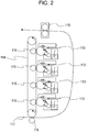
- Fig. 2 is a schematic sectional view of the electrophotographic apparatus according to the second exemplary embodiment of the present invention.
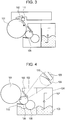
- Fig. 3 is an enlargement of one of process cartridges attached to the electrophotographic apparatus illustrated in Fig. 2 .
- the process cartridge includes an image carrying member 101, a charging device including a charging member 111, a developing device including a developing roller 106, and a cleaning device including a cleaning member 112.
- the process cartridge is attachable to and detachable from the body of the electrophotographic apparatus illustrated in Fig. 2 .
- the image carrying member 101 is uniformly charged by the charging member 111 (primary charging).
- the charging member 111 is connected to a bias power source (not illustrated).
- the potential of the charged image carrying member 101 may be about -800 V or higher and about -400 V or lower.
- the charged image carrying member 101 is exposed to exposure light 113 for drawing an electrostatic latent image, whereby an electrostatic latent image is formed on the surface of the image carrying member 101.
- the exposure light 113 may be either light from a light-emitting diode (LED) or laser light.
- the potential in the portion of the surface of the image carrying member 101 that has been exposed to the exposure light 113 may be about -200 V or higher and about -100 V or lower.
- toner that has been negatively charged by the developing roller 106 provided in the process cartridge that is detachably attached to the body of the electrophotographic apparatus is supplied (for development) to the electrostatic latent image, whereby a toner image is formed on the image carrying member 101. That is, the electrostatic latent image is converted into a visible image.
- a voltage of about -500 V or higher and about -300 V or lower may be applied to the developing roller 106 from a bias power source (not illustrated).
- the developing roller 106 and the image carrying member 101 that are in contact with each other may form a nip therebetween having a width of about 0.5 mm or larger and about 3 mm or smaller.
- the toner image formed on the image carrying member 101 undergoes primary transfer to an intermediate transfer belt 114.
- a primary transfer member 115 is in contact with the back side of the intermediate transfer belt 114.
- a voltage of about +100 V or higher and about +1500 V or lower may be applied to the primary transfer member 115. With the application of the voltage, the toner image having a negative polarity undergoes primary transfer from the image carrying member 101 to the intermediate transfer belt 114.
- the primary transfer member 115 may have either a roller shape or a blade shape.
- the electrophotographic apparatus is a full-color image forming apparatus
- the above steps of charging, exposure, development, and primary transfer are performed for each of colors of yellow, cyan, magenta, and black.
- the electrophotographic apparatus illustrated in Fig. 2 includes four process cartridges that contain toners having the respective colors.
- the process cartridges are detachably attached to the body of the electrophotographic apparatus.
- the above steps of charging, exposure, development, and primary transfer are performed sequentially with predetermined time lags.
- toner images in the four respective colors that in combination express a full color image are superposed on the intermediate transfer belt 114.
- the superposition of toner images on the intermediate transfer belt 114 is conveyed to a position that faces a secondary transfer member 116.
- a recording sheet as a transfer material is conveyed at a predetermined timing along a conveying route 117 into a nip between the intermediate transfer belt 114 and the secondary transfer member 116.
- a secondary transfer bias is applied to the secondary transfer member 116, whereby the superposition of toner images on the intermediate transfer belt 114 is transferred to the recording sheet.
- the bias voltage applied to the secondary transfer member 116 in the above step may be about +1000 V or higher and about +4000 V or lower.
- the recording sheet having the superposition of toner images transferred thereto by the secondary transfer member 116 is then conveyed to a fixing device 118, where the superposition of toner images on the recording sheet is fused and is fixed to the recording sheet. Subsequently, the recording sheet is discharged to the outside of the electrophotographic apparatus. Thus, a printing operation ends.
- Portions of the toner images remaining on the image carrying members 101 without being transferred from the image carrying members 101 to the intermediate transfer belt 114 are scraped from the image carrying members 101 by the respective cleaning members 112 that clean the surfaces of the image carrying members 101. Thus, the surfaces of the image carrying members 101 are cleaned.
- Spherical resin particles used in working examples and comparative examples are summarized in Table 1.
- Spherical Resin Particles 1 to 4 were used in Working Examples 1 to 4, respectively.
- Spherical Resin Particles 5 to 9 were used in Comparative Examples 1 to 5, respectively.
- the weight-average particle size and the average circularity were measured by the above-described methods.
- Table 1 Spherical Resin Particle Base material Product Weight-average particle size ( ⁇ m) Average Circularity 1 Urethane resin "UCN5070D Clear” of Dainichiseika Color & Chemicals Mfg. Co., Ltd. 7.2 0.978 2 Urethane resin "UCN5150D Clear” of Dainichiseika Color & Chemicals Mfg.
- a semiconductive composite 1 was prepared by mixing substances given in Table 2 at room temperature by using an agitator.
- Table 2 Polysiloxane having vinyl group at terminal "DMS-V42" of AZmax. Co 100 parts by mass Hydrosilyl cross-linker "HMS-151” of AZmax. Co 5.4 parts by mass Platinum catalyst "SIP6831-3” of AZmax. Co 0.15 parts by mass Carbon black "#970" of Mitsubishi Chemical Corporation 8.0 parts by mass
- a primer ("DY35-051” manufactured by Dow Corning Toray Co., Ltd.) was applied to a metal core made of SUS304 (a kind of stainless steel according to a Japanese Industrial Standard) and having a diameter of 6 mm and a length of 264 mm.
- the metal core was baked at 150°C for 30 minutes and was placed into a mold.
- the semiconductive composite 1 was injected into a cavity of the mold.
- the mold was heated at 150°C for 15 minutes and was released.
- the resultant was heated at 200°C for two hours, whereby a curing reaction was complete.
- a conductive elastic layer 1 having a diameter of 11.5 mm was formed.
- Methyl ethyl ketone was added to the paint 1 for a conductive surface layer prepared as described above, whereby the paint 1 for conductive surface layer was adjusted to have a solid content of 28%. Then, the paint 1 was applied over the conductive elastic layer 1, molded as described above, by dipping. Subsequently, the resultant was dried in an oven at 80°C for 15 minutes and was cured in an oven at 140°C for four hours. Thus, a developing roller was obtained. The thickness of the surface layer was 10.2 ⁇ m.
- a vibration test described below was conducted on the above cartridge. After conducting the vibration test, the process cartridge was left in an environment that is at a temperature of 23°C and with a humidity of 55% for 24 hours. Then, a seal member that separates a developing chamber and a toner container included in the developing device of the cartridge was removed. Subsequently, the process cartridge was attached to the above color laser printer. Then, a cyan halftone image was printed on each of 100 A4-size recording sheets (color-laser-copier (CLC) paper manufactured by Canon Kabusiki Kaisha and having a basis weight of 81.4 g/m 2 ). The printing was continuously performed in an environment that is at a temperature of 23°C and with a humidity of 55%.
- CLC color-laser-copier
- Table 6 summarizes the Martens hardness, the restoring elastic power, and the banding grade of each of Spherical Resin Particles 1 to 9.
- the spherical resin particles provided between the developing roller and the toner regulating member had a high Martens hardness. Therefore, a thrust memory probably attributed to a physical stress applied to the developing roller was generated. Consequently, banding attributed to the thrust memory occurred in the halftone images. However, the thrust memory was gradually eliminated as image formation was continued, and substantially no banding occurred in the twentieth and subsequent halftone images.
- the developing device even if the developing device is stored while being subject to vibration attributed to long-time transportation, an electrostatic memory does not tend to be generated on the developing roller. Therefore, the developing device does not tend to cause banding in halftone images. Furthermore, according to the present invention, a process cartridge and an electrophotographic apparatus that are capable of forming high-quality electrophotographic images are provided.
Landscapes
- Physics & Mathematics (AREA)
- General Physics & Mathematics (AREA)
- Dry Development In Electrophotography (AREA)
- Electrophotography Configuration And Component (AREA)
- Developing Agents For Electrophotography (AREA)
Applications Claiming Priority (1)
| Application Number | Priority Date | Filing Date | Title |
|---|---|---|---|
| JP2013135659 | 2013-06-27 |
Publications (2)
| Publication Number | Publication Date |
|---|---|
| EP2818937A1 EP2818937A1 (en) | 2014-12-31 |
| EP2818937B1 true EP2818937B1 (en) | 2017-07-19 |
Family
ID=50841549
Family Applications (1)
| Application Number | Title | Priority Date | Filing Date |
|---|---|---|---|
| EP14001892.0A Active EP2818937B1 (en) | 2013-06-27 | 2014-05-30 | Developing device, process cartridge, and electrophotographic apparatus |
Country Status (5)
| Country | Link |
|---|---|
| US (1) | US9128411B2 (enExample) |
| EP (1) | EP2818937B1 (enExample) |
| JP (1) | JP6312531B2 (enExample) |
| KR (1) | KR101698239B1 (enExample) |
| CN (1) | CN104252116B (enExample) |
Families Citing this family (4)
| Publication number | Priority date | Publication date | Assignee | Title |
|---|---|---|---|---|
| EP3037890B1 (en) | 2014-12-25 | 2019-06-26 | Canon Kabushiki Kaisha | Developing unit, process cartridge, and electrophotographic apparatus |
| US9904199B2 (en) * | 2015-10-26 | 2018-02-27 | Canon Kabushiki Kaisha | Charging member having outer surface with concave portions bearing exposed elastic particles, and electrophotographic apparatus |
| JP6679367B2 (ja) * | 2016-03-25 | 2020-04-15 | キヤノン株式会社 | プロセスカートリッジ |
| JP7297425B2 (ja) | 2018-11-14 | 2023-06-26 | キヤノン株式会社 | 現像装置、プロセスカートリッジ及び画像形成装置 |
Family Cites Families (17)
| Publication number | Priority date | Publication date | Assignee | Title |
|---|---|---|---|---|
| US5177537A (en) | 1989-12-20 | 1993-01-05 | Canon Kabushiki Kaisha | Developing apparatus with elastic regulating member urged to a developer carrying member |
| JP3397510B2 (ja) | 1994-12-21 | 2003-04-14 | キヤノン株式会社 | 現像装置及びプロセスカートリッジ |
| JPH08211728A (ja) * | 1995-02-02 | 1996-08-20 | Canon Inc | 現像装置 |
| US5732310A (en) * | 1995-04-21 | 1998-03-24 | Canon Kabushiki Kaisha | Image forming apparatus having cleaning device for cleaning intermediate transfer member |
| JP2002108094A (ja) * | 2000-09-29 | 2002-04-10 | Canon Inc | 現像装置 |
| JP2002278262A (ja) * | 2001-03-16 | 2002-09-27 | Canon Inc | 現像装置及びプロセスカートリッジ |
| US20040223789A1 (en) * | 2003-02-28 | 2004-11-11 | Canon Kabushiki Kaisha | Developing apparatus |
| US20060153600A1 (en) * | 2005-01-13 | 2006-07-13 | Ming-Cheng Huang | Doctor blade within toner cartridge, material and structure thereof |
| JP2007033538A (ja) | 2005-07-22 | 2007-02-08 | Canon Inc | 現像装置及びプロセスカートリッジ |
| JP2007233255A (ja) | 2006-03-03 | 2007-09-13 | Tokai Rubber Ind Ltd | 現像ロール |
| WO2008044427A1 (en) | 2006-10-06 | 2008-04-17 | Canon Kabushiki Kaisha | Developing roller, developing apparatus using the same and image forming apparatus |
| JP2009116009A (ja) * | 2007-11-06 | 2009-05-28 | Tokai Rubber Ind Ltd | 導電性ロール |
| JP5419584B2 (ja) * | 2008-09-01 | 2014-02-19 | キヤノン株式会社 | カートリッジ及び電子写真画像形成装置 |
| JP2011123416A (ja) * | 2009-12-14 | 2011-06-23 | Canon Inc | 画像形成装置 |
| JP2011242732A (ja) * | 2010-05-21 | 2011-12-01 | Canon Inc | 画像形成装置及びプロセスカートリッジ |
| EP2733549B1 (en) | 2011-07-15 | 2016-04-20 | Canon Kabushiki Kaisha | Developer carrier, process cartridge for electrophotography, and electrophotographic image-forming device |
| JP6202360B2 (ja) * | 2013-01-24 | 2017-09-27 | 株式会社リコー | クリーニングブレード、並びにこれを用いた画像形成装置及びプロセスカートリッジ |
-
2014
- 2014-05-29 US US14/290,756 patent/US9128411B2/en active Active
- 2014-05-29 CN CN201410235698.5A patent/CN104252116B/zh active Active
- 2014-05-30 KR KR1020140065711A patent/KR101698239B1/ko active Active
- 2014-05-30 EP EP14001892.0A patent/EP2818937B1/en active Active
- 2014-06-03 JP JP2014115033A patent/JP6312531B2/ja active Active
Non-Patent Citations (1)
| Title |
|---|
| None * |
Also Published As
| Publication number | Publication date |
|---|---|
| CN104252116A (zh) | 2014-12-31 |
| JP2015028609A (ja) | 2015-02-12 |
| KR20150001616A (ko) | 2015-01-06 |
| EP2818937A1 (en) | 2014-12-31 |
| JP6312531B2 (ja) | 2018-04-18 |
| KR101698239B1 (ko) | 2017-01-19 |
| US9128411B2 (en) | 2015-09-08 |
| CN104252116B (zh) | 2018-07-10 |
| US20150003862A1 (en) | 2015-01-01 |
Similar Documents
| Publication | Publication Date | Title |
|---|---|---|
| US9921518B2 (en) | Developing roller, with conductive elastic layer having exposed protrusions, cartridge and apparatus | |
| JP6590661B2 (ja) | 電子写真用部材、プロセスカートリッジおよび画像形成装置 | |
| JP5928001B2 (ja) | 現像ローラ | |
| JP5786532B2 (ja) | 保護剤供給部材、保護層形成装置、及び画像形成装置 | |
| US10571825B1 (en) | Electrophotographic member, electrophotographic process cartridge and electrophotographic image forming apparatus | |
| JP2016164654A (ja) | 電子写真用部材、プロセスカートリッジおよび電子写真画像形成装置 | |
| EP2818937B1 (en) | Developing device, process cartridge, and electrophotographic apparatus | |
| JP2009156995A (ja) | 帯電ロール用クリーニングロール、帯電装置、プロセスカートリッジ、画像形成装置及び画像形成方法 | |
| JP2013073003A (ja) | 現像装置および画像形成装置 | |
| JP2015121761A (ja) | 保護層形成装置及び画像形成装置 | |
| KR100306066B1 (ko) | 클리닝 부재, 클리닝 장치, 및 화상 형성 장치 및 클리닝 장치가 이용되는 프로세스 카트리지 | |
| JP7034813B2 (ja) | 画像形成装置、帯電部材、カートリッジ、及び帯電部材の製造方法 | |
| JP3975326B2 (ja) | 導電部材及び電子写真装置 | |
| JP7783679B2 (ja) | 電子写真部材、電子写真プロセスカートリッジおよび電子写真画像形成装置 | |
| JP6270129B2 (ja) | 画像形成装置およびプロセスカートリッジ | |
| JP6611595B2 (ja) | 現像装置、プロセスカートリッジ、および電子写真装置 | |
| US9405215B2 (en) | Developer supply member, developing unit, and image forming apparatus | |
| JP4069352B2 (ja) | 導電部材及び電子写真装置 | |
| JP2003167398A (ja) | 導電部材及び電子写真装置 | |
| JP2007264254A (ja) | 帯電部材及び電子写真装置 | |
| JP2007114605A (ja) | 画像形成装置 | |
| JP5807709B2 (ja) | 保護剤供給部材 | |
| JP2010169941A (ja) | 帯電部材、帯電装置、プロセスカートリッジ及び画像形成装置 | |
| JP2008015075A (ja) | 現像ローラ | |
| JP2017161873A (ja) | 像担持体保護剤、保護層形成装置、画像形成方法、画像形成装置、及びプロセスカートリッジ |
Legal Events
| Date | Code | Title | Description |
|---|---|---|---|
| PUAI | Public reference made under article 153(3) epc to a published international application that has entered the european phase |
Free format text: ORIGINAL CODE: 0009012 |
|
| 17P | Request for examination filed |
Effective date: 20140530 |
|
| AK | Designated contracting states |
Kind code of ref document: A1 Designated state(s): AL AT BE BG CH CY CZ DE DK EE ES FI FR GB GR HR HU IE IS IT LI LT LU LV MC MK MT NL NO PL PT RO RS SE SI SK SM TR |
|
| AX | Request for extension of the european patent |
Extension state: BA ME |
|
| R17P | Request for examination filed (corrected) |
Effective date: 20150630 |
|
| RBV | Designated contracting states (corrected) |
Designated state(s): AL AT BE BG CH CY CZ DE DK EE ES FI FR GB GR HR HU IE IS IT LI LT LU LV MC MK MT NL NO PL PT RO RS SE SI SK SM TR |
|
| GRAP | Despatch of communication of intention to grant a patent |
Free format text: ORIGINAL CODE: EPIDOSNIGR1 |
|
| INTG | Intention to grant announced |
Effective date: 20170208 |
|
| GRAS | Grant fee paid |
Free format text: ORIGINAL CODE: EPIDOSNIGR3 |
|
| GRAA | (expected) grant |
Free format text: ORIGINAL CODE: 0009210 |
|
| RAP1 | Party data changed (applicant data changed or rights of an application transferred) |
Owner name: CANON KABUSHIKI KAISHA |
|
| AK | Designated contracting states |
Kind code of ref document: B1 Designated state(s): AL AT BE BG CH CY CZ DE DK EE ES FI FR GB GR HR HU IE IS IT LI LT LU LV MC MK MT NL NO PL PT RO RS SE SI SK SM TR |
|
| REG | Reference to a national code |
Ref country code: GB Ref legal event code: FG4D |
|
| REG | Reference to a national code |
Ref country code: CH Ref legal event code: EP |
|
| REG | Reference to a national code |
Ref country code: IE Ref legal event code: FG4D |
|
| REG | Reference to a national code |
Ref country code: AT Ref legal event code: REF Ref document number: 910954 Country of ref document: AT Kind code of ref document: T Effective date: 20170815 |
|
| REG | Reference to a national code |
Ref country code: DE Ref legal event code: R096 Ref document number: 602014011837 Country of ref document: DE |
|
| REG | Reference to a national code |
Ref country code: NL Ref legal event code: MP Effective date: 20170719 |
|
| REG | Reference to a national code |
Ref country code: LT Ref legal event code: MG4D |
|
| REG | Reference to a national code |
Ref country code: AT Ref legal event code: MK05 Ref document number: 910954 Country of ref document: AT Kind code of ref document: T Effective date: 20170719 |
|
| PG25 | Lapsed in a contracting state [announced via postgrant information from national office to epo] |
Ref country code: LT Free format text: LAPSE BECAUSE OF FAILURE TO SUBMIT A TRANSLATION OF THE DESCRIPTION OR TO PAY THE FEE WITHIN THE PRESCRIBED TIME-LIMIT Effective date: 20170719 Ref country code: HR Free format text: LAPSE BECAUSE OF FAILURE TO SUBMIT A TRANSLATION OF THE DESCRIPTION OR TO PAY THE FEE WITHIN THE PRESCRIBED TIME-LIMIT Effective date: 20170719 Ref country code: AT Free format text: LAPSE BECAUSE OF FAILURE TO SUBMIT A TRANSLATION OF THE DESCRIPTION OR TO PAY THE FEE WITHIN THE PRESCRIBED TIME-LIMIT Effective date: 20170719 Ref country code: NO Free format text: LAPSE BECAUSE OF FAILURE TO SUBMIT A TRANSLATION OF THE DESCRIPTION OR TO PAY THE FEE WITHIN THE PRESCRIBED TIME-LIMIT Effective date: 20171019 Ref country code: NL Free format text: LAPSE BECAUSE OF FAILURE TO SUBMIT A TRANSLATION OF THE DESCRIPTION OR TO PAY THE FEE WITHIN THE PRESCRIBED TIME-LIMIT Effective date: 20170719 Ref country code: FI Free format text: LAPSE BECAUSE OF FAILURE TO SUBMIT A TRANSLATION OF THE DESCRIPTION OR TO PAY THE FEE WITHIN THE PRESCRIBED TIME-LIMIT Effective date: 20170719 Ref country code: SE Free format text: LAPSE BECAUSE OF FAILURE TO SUBMIT A TRANSLATION OF THE DESCRIPTION OR TO PAY THE FEE WITHIN THE PRESCRIBED TIME-LIMIT Effective date: 20170719 |
|
| PG25 | Lapsed in a contracting state [announced via postgrant information from national office to epo] |
Ref country code: PL Free format text: LAPSE BECAUSE OF FAILURE TO SUBMIT A TRANSLATION OF THE DESCRIPTION OR TO PAY THE FEE WITHIN THE PRESCRIBED TIME-LIMIT Effective date: 20170719 Ref country code: RS Free format text: LAPSE BECAUSE OF FAILURE TO SUBMIT A TRANSLATION OF THE DESCRIPTION OR TO PAY THE FEE WITHIN THE PRESCRIBED TIME-LIMIT Effective date: 20170719 Ref country code: ES Free format text: LAPSE BECAUSE OF FAILURE TO SUBMIT A TRANSLATION OF THE DESCRIPTION OR TO PAY THE FEE WITHIN THE PRESCRIBED TIME-LIMIT Effective date: 20170719 Ref country code: BG Free format text: LAPSE BECAUSE OF FAILURE TO SUBMIT A TRANSLATION OF THE DESCRIPTION OR TO PAY THE FEE WITHIN THE PRESCRIBED TIME-LIMIT Effective date: 20171019 Ref country code: IS Free format text: LAPSE BECAUSE OF FAILURE TO SUBMIT A TRANSLATION OF THE DESCRIPTION OR TO PAY THE FEE WITHIN THE PRESCRIBED TIME-LIMIT Effective date: 20171119 Ref country code: LV Free format text: LAPSE BECAUSE OF FAILURE TO SUBMIT A TRANSLATION OF THE DESCRIPTION OR TO PAY THE FEE WITHIN THE PRESCRIBED TIME-LIMIT Effective date: 20170719 Ref country code: GR Free format text: LAPSE BECAUSE OF FAILURE TO SUBMIT A TRANSLATION OF THE DESCRIPTION OR TO PAY THE FEE WITHIN THE PRESCRIBED TIME-LIMIT Effective date: 20171020 |
|
| REG | Reference to a national code |
Ref country code: DE Ref legal event code: R097 Ref document number: 602014011837 Country of ref document: DE |
|
| PG25 | Lapsed in a contracting state [announced via postgrant information from national office to epo] |
Ref country code: DK Free format text: LAPSE BECAUSE OF FAILURE TO SUBMIT A TRANSLATION OF THE DESCRIPTION OR TO PAY THE FEE WITHIN THE PRESCRIBED TIME-LIMIT Effective date: 20170719 Ref country code: RO Free format text: LAPSE BECAUSE OF FAILURE TO SUBMIT A TRANSLATION OF THE DESCRIPTION OR TO PAY THE FEE WITHIN THE PRESCRIBED TIME-LIMIT Effective date: 20170719 Ref country code: CZ Free format text: LAPSE BECAUSE OF FAILURE TO SUBMIT A TRANSLATION OF THE DESCRIPTION OR TO PAY THE FEE WITHIN THE PRESCRIBED TIME-LIMIT Effective date: 20170719 |
|
| PLBE | No opposition filed within time limit |
Free format text: ORIGINAL CODE: 0009261 |
|
| STAA | Information on the status of an ep patent application or granted ep patent |
Free format text: STATUS: NO OPPOSITION FILED WITHIN TIME LIMIT |
|
| PG25 | Lapsed in a contracting state [announced via postgrant information from national office to epo] |
Ref country code: SM Free format text: LAPSE BECAUSE OF FAILURE TO SUBMIT A TRANSLATION OF THE DESCRIPTION OR TO PAY THE FEE WITHIN THE PRESCRIBED TIME-LIMIT Effective date: 20170719 Ref country code: SK Free format text: LAPSE BECAUSE OF FAILURE TO SUBMIT A TRANSLATION OF THE DESCRIPTION OR TO PAY THE FEE WITHIN THE PRESCRIBED TIME-LIMIT Effective date: 20170719 Ref country code: IT Free format text: LAPSE BECAUSE OF FAILURE TO SUBMIT A TRANSLATION OF THE DESCRIPTION OR TO PAY THE FEE WITHIN THE PRESCRIBED TIME-LIMIT Effective date: 20170719 Ref country code: EE Free format text: LAPSE BECAUSE OF FAILURE TO SUBMIT A TRANSLATION OF THE DESCRIPTION OR TO PAY THE FEE WITHIN THE PRESCRIBED TIME-LIMIT Effective date: 20170719 |
|
| 26N | No opposition filed |
Effective date: 20180420 |
|
| PG25 | Lapsed in a contracting state [announced via postgrant information from national office to epo] |
Ref country code: SI Free format text: LAPSE BECAUSE OF FAILURE TO SUBMIT A TRANSLATION OF THE DESCRIPTION OR TO PAY THE FEE WITHIN THE PRESCRIBED TIME-LIMIT Effective date: 20170719 |
|
| REG | Reference to a national code |
Ref country code: CH Ref legal event code: PL |
|
| REG | Reference to a national code |
Ref country code: BE Ref legal event code: MM Effective date: 20180531 |
|
| PG25 | Lapsed in a contracting state [announced via postgrant information from national office to epo] |
Ref country code: MC Free format text: LAPSE BECAUSE OF FAILURE TO SUBMIT A TRANSLATION OF THE DESCRIPTION OR TO PAY THE FEE WITHIN THE PRESCRIBED TIME-LIMIT Effective date: 20170719 |
|
| REG | Reference to a national code |
Ref country code: IE Ref legal event code: MM4A |
|
| PG25 | Lapsed in a contracting state [announced via postgrant information from national office to epo] |
Ref country code: CH Free format text: LAPSE BECAUSE OF NON-PAYMENT OF DUE FEES Effective date: 20180531 Ref country code: LI Free format text: LAPSE BECAUSE OF NON-PAYMENT OF DUE FEES Effective date: 20180531 |
|
| PG25 | Lapsed in a contracting state [announced via postgrant information from national office to epo] |
Ref country code: LU Free format text: LAPSE BECAUSE OF NON-PAYMENT OF DUE FEES Effective date: 20180530 |
|
| PG25 | Lapsed in a contracting state [announced via postgrant information from national office to epo] |
Ref country code: IE Free format text: LAPSE BECAUSE OF NON-PAYMENT OF DUE FEES Effective date: 20180530 Ref country code: FR Free format text: LAPSE BECAUSE OF NON-PAYMENT OF DUE FEES Effective date: 20180531 |
|
| PG25 | Lapsed in a contracting state [announced via postgrant information from national office to epo] |
Ref country code: BE Free format text: LAPSE BECAUSE OF NON-PAYMENT OF DUE FEES Effective date: 20180531 |
|
| PG25 | Lapsed in a contracting state [announced via postgrant information from national office to epo] |
Ref country code: MT Free format text: LAPSE BECAUSE OF NON-PAYMENT OF DUE FEES Effective date: 20180530 |
|
| PG25 | Lapsed in a contracting state [announced via postgrant information from national office to epo] |
Ref country code: TR Free format text: LAPSE BECAUSE OF FAILURE TO SUBMIT A TRANSLATION OF THE DESCRIPTION OR TO PAY THE FEE WITHIN THE PRESCRIBED TIME-LIMIT Effective date: 20170719 |
|
| PG25 | Lapsed in a contracting state [announced via postgrant information from national office to epo] |
Ref country code: HU Free format text: LAPSE BECAUSE OF FAILURE TO SUBMIT A TRANSLATION OF THE DESCRIPTION OR TO PAY THE FEE WITHIN THE PRESCRIBED TIME-LIMIT; INVALID AB INITIO Effective date: 20140530 Ref country code: PT Free format text: LAPSE BECAUSE OF FAILURE TO SUBMIT A TRANSLATION OF THE DESCRIPTION OR TO PAY THE FEE WITHIN THE PRESCRIBED TIME-LIMIT Effective date: 20170719 |
|
| PG25 | Lapsed in a contracting state [announced via postgrant information from national office to epo] |
Ref country code: CY Free format text: LAPSE BECAUSE OF FAILURE TO SUBMIT A TRANSLATION OF THE DESCRIPTION OR TO PAY THE FEE WITHIN THE PRESCRIBED TIME-LIMIT Effective date: 20170719 Ref country code: MK Free format text: LAPSE BECAUSE OF NON-PAYMENT OF DUE FEES Effective date: 20170719 |
|
| PG25 | Lapsed in a contracting state [announced via postgrant information from national office to epo] |
Ref country code: AL Free format text: LAPSE BECAUSE OF FAILURE TO SUBMIT A TRANSLATION OF THE DESCRIPTION OR TO PAY THE FEE WITHIN THE PRESCRIBED TIME-LIMIT Effective date: 20170719 |
|
| PGFP | Annual fee paid to national office [announced via postgrant information from national office to epo] |
Ref country code: DE Payment date: 20250423 Year of fee payment: 12 |
|
| PGFP | Annual fee paid to national office [announced via postgrant information from national office to epo] |
Ref country code: GB Payment date: 20260317 Year of fee payment: 13 |