EP2812965B1 - Lüfter und anordnung aufweisend einen derartigen lüfter - Google Patents
Lüfter und anordnung aufweisend einen derartigen lüfter Download PDFInfo
- Publication number
- EP2812965B1 EP2812965B1 EP13704716.3A EP13704716A EP2812965B1 EP 2812965 B1 EP2812965 B1 EP 2812965B1 EP 13704716 A EP13704716 A EP 13704716A EP 2812965 B1 EP2812965 B1 EP 2812965B1
- Authority
- EP
- European Patent Office
- Prior art keywords
- fan
- hat rail
- rail
- base plate
- tilting
- Prior art date
- Legal status (The legal status is an assumption and is not a legal conclusion. Google has not performed a legal analysis and makes no representation as to the accuracy of the status listed.)
- Active
Links
- 238000003780 insertion Methods 0.000 claims description 11
- 230000037431 insertion Effects 0.000 claims description 11
- 239000000463 material Substances 0.000 claims description 4
- 238000009434 installation Methods 0.000 description 3
- 238000010276 construction Methods 0.000 description 2
- 238000009423 ventilation Methods 0.000 description 2
- 238000007664 blowing Methods 0.000 description 1
- 230000005484 gravity Effects 0.000 description 1
- 238000010438 heat treatment Methods 0.000 description 1
- 230000001105 regulatory effect Effects 0.000 description 1
- 239000000725 suspension Substances 0.000 description 1
Images


Classifications
-
- F—MECHANICAL ENGINEERING; LIGHTING; HEATING; WEAPONS; BLASTING
- F04—POSITIVE - DISPLACEMENT MACHINES FOR LIQUIDS; PUMPS FOR LIQUIDS OR ELASTIC FLUIDS
- F04D—NON-POSITIVE-DISPLACEMENT PUMPS
- F04D19/00—Axial-flow pumps
- F04D19/002—Axial flow fans
-
- F—MECHANICAL ENGINEERING; LIGHTING; HEATING; WEAPONS; BLASTING
- F04—POSITIVE - DISPLACEMENT MACHINES FOR LIQUIDS; PUMPS FOR LIQUIDS OR ELASTIC FLUIDS
- F04D—NON-POSITIVE-DISPLACEMENT PUMPS
- F04D29/00—Details, component parts, or accessories
- F04D29/60—Mounting; Assembling; Disassembling
- F04D29/601—Mounting; Assembling; Disassembling specially adapted for elastic fluid pumps
-
- H—ELECTRICITY
- H02—GENERATION; CONVERSION OR DISTRIBUTION OF ELECTRIC POWER
- H02B—BOARDS, SUBSTATIONS OR SWITCHING ARRANGEMENTS FOR THE SUPPLY OR DISTRIBUTION OF ELECTRIC POWER
- H02B1/00—Frameworks, boards, panels, desks, casings; Details of substations or switching arrangements
- H02B1/015—Boards, panels, desks; Parts thereof or accessories therefor
- H02B1/04—Mounting thereon of switches or of other devices in general, the switch or device having, or being without, casing
- H02B1/052—Mounting on rails
-
- H—ELECTRICITY
- H02—GENERATION; CONVERSION OR DISTRIBUTION OF ELECTRIC POWER
- H02B—BOARDS, SUBSTATIONS OR SWITCHING ARRANGEMENTS FOR THE SUPPLY OR DISTRIBUTION OF ELECTRIC POWER
- H02B1/00—Frameworks, boards, panels, desks, casings; Details of substations or switching arrangements
- H02B1/56—Cooling; Ventilation
- H02B1/565—Cooling; Ventilation for cabinets
-
- H—ELECTRICITY
- H05—ELECTRIC TECHNIQUES NOT OTHERWISE PROVIDED FOR
- H05K—PRINTED CIRCUITS; CASINGS OR CONSTRUCTIONAL DETAILS OF ELECTRIC APPARATUS; MANUFACTURE OF ASSEMBLAGES OF ELECTRICAL COMPONENTS
- H05K7/00—Constructional details common to different types of electric apparatus
- H05K7/20—Modifications to facilitate cooling, ventilating, or heating
- H05K7/20009—Modifications to facilitate cooling, ventilating, or heating using a gaseous coolant in electronic enclosures
- H05K7/20136—Forced ventilation, e.g. by fans
- H05K7/20172—Fan mounting or fan specifications
-
- F—MECHANICAL ENGINEERING; LIGHTING; HEATING; WEAPONS; BLASTING
- F04—POSITIVE - DISPLACEMENT MACHINES FOR LIQUIDS; PUMPS FOR LIQUIDS OR ELASTIC FLUIDS
- F04D—NON-POSITIVE-DISPLACEMENT PUMPS
- F04D25/00—Pumping installations or systems
- F04D25/02—Units comprising pumps and their driving means
- F04D25/08—Units comprising pumps and their driving means the working fluid being air, e.g. for ventilation
-
- F—MECHANICAL ENGINEERING; LIGHTING; HEATING; WEAPONS; BLASTING
- F04—POSITIVE - DISPLACEMENT MACHINES FOR LIQUIDS; PUMPS FOR LIQUIDS OR ELASTIC FLUIDS
- F04D—NON-POSITIVE-DISPLACEMENT PUMPS
- F04D29/00—Details, component parts, or accessories
- F04D29/60—Mounting; Assembling; Disassembling
-
- H—ELECTRICITY
- H02—GENERATION; CONVERSION OR DISTRIBUTION OF ELECTRIC POWER
- H02B—BOARDS, SUBSTATIONS OR SWITCHING ARRANGEMENTS FOR THE SUPPLY OR DISTRIBUTION OF ELECTRIC POWER
- H02B1/00—Frameworks, boards, panels, desks, casings; Details of substations or switching arrangements
- H02B1/26—Casings; Parts thereof or accessories therefor
- H02B1/52—Mobile units, e.g. for work sites
-
- H—ELECTRICITY
- H02—GENERATION; CONVERSION OR DISTRIBUTION OF ELECTRIC POWER
- H02B—BOARDS, SUBSTATIONS OR SWITCHING ARRANGEMENTS FOR THE SUPPLY OR DISTRIBUTION OF ELECTRIC POWER
- H02B1/00—Frameworks, boards, panels, desks, casings; Details of substations or switching arrangements
- H02B1/56—Cooling; Ventilation
Definitions
- the invention relates to a fan and an arrangement comprising such a fan.
- the attachment of the fan, for example, in a control cabinet usually takes place by means of a DIN rail.
- a suitable for a rail mounting device is in the context of DIN rail mounted devices in the DE 10 2007 015 470 A1 described.
- an upper and a lower holding device are provided on a rear wall of a device.
- the upper holding device hangs in the upper edge of the DIN rail and then tilts the device back down, the lower holding device enters into a releasable snap engagement with the lower edge of the top hat rail.
- the lower holding device is released and the device can be tilted up and removed.
- a device has a very large depth, such. a ventilation, heating or lighting device and the installation space above the DIN rail is low, there are difficulties in attaching the device to the top hat rail, since a tipping is only possible to a limited extent.
- the device may only have a limited height in the known fastening device, otherwise the rear wall must be formed obliquely in order to achieve the necessary tilt angle. This reduces the installation space inside the device.
- JP 2009 290 018 A relates to a structure for mounting a rail capable of integrally forming a structure for mounting an apparatus body to a rail on the apparatus body.
- the engaging pieces of the rail engage with a pair of engaging grooves, and the movement in the front-rear direction is regulated.
- JP 2008 177 597 A refers to a rail mountable electronic device mounted to a rail by rotating the electronic device. To install the device, the rail has a pair of locking members which engage a pair of engagement means of the device.
- JP H07 162 167 A describes an electrical device installable on a mounting rail having on both side edges a rail mounting and insertion groove formed on a lower bottom surface 1 of the device with supporting stepped edges and open edges.
- DE 10 2009 014 654 A1 relates to a ventilation system with an adapter for attachment to a profile rail.
- the fan is rotatably mounted on the adapter for adjusting an air flow direction.
- the distance between the fan and the adapter is adjustable to set an airflow exit point of the fan.
- the fan is provided in a fan housing, and the adapter is movably attached to the fan housing to adjust the airflow direction.
- EP 2 118 968 B1 describes an electrical terminal block having a base and four or more tabs projecting downwardly from a flat bottom. These are used to lock the block against a fixed support, such as a DIN rail with coplanar edges, in a plane parallel to the bottom of the block.
- the invention is based on the object to provide a fan that requires a small installation space for mounting / dismounting. Furthermore, an arrangement comprising such a fan should be specified. This object is achieved for the fan by the subject-matter of claim 1 and for the arrangement by the subject-matter of claim 10.
- this object is achieved by a fan with a nozzle which is fixed to a base plate, wherein the base plate has on its rear wall a fastening device with at least one upper holding means and at least one lower holding means for securing the fan to a DIN rail.
- the upper holding device and the lower holding device engage in the attached state an upper edge or a lower edge of the DIN rail.
- the two holding devices are arranged offset to one another and in a direction which, in the attached state of the fan parallel to Longitudinal axis of the top hat rail runs.
- the mutually facing ends of the holding means form inner ends, wherein between the inner end of the upper holding means and the inner end of the lower holding means is a distance of a width which is greater than the distance between the upper edge and the lower edge of the hat rail, so that the fan by tilting in a Einsetzkippraum about a tilt axis perpendicular to a DIN rail longitudinal direction in the top hat rail is used, wherein the nozzle is connected to the base plate by a one-dimensional pivot member for pivoting the fan about a pivot axis, wherein the rear wall of the nozzle convexly curved and in a corresponding concave curved front wall of the base plate is received, and wherein the side walls and the front wall of the base plate and the rear wall of the nozzle have louvers.
- the hitherto known "tilting upwards” is changed into a tilting or turning of the fan about a tilting axis which is parallel to the longitudinal axis of the fan or coincides with it.
- This makes it possible, on the one hand, to make the rear wall of the fan completely straight even at a relatively high overall height, ie without the otherwise required bevel.
- the clearance above the top-hat rail or the fan is considerably lower than in the past, due to this different type of hook-in movement, even with a very large fan depth.
- a locking bolt is preferably provided which locks the fan in the attached state against tilting.
- the locking bolt is preferably designed such that it can be unlocked when inserting the fan by tilting in Einsetzkippides. So he snaps without a separate operation.
- the upper and lower holding means have mutually facing bevels to reduce the tilt angle necessary for insertion.
- the upper and lower holding means may be of different lengths, the upper holding means being preferably longer than the lower holding means.
- the two holding devices are formed substantially rotationally symmetrical about the tilt axis.
- the construction is particularly simple when the holding devices are integrally formed with a rear wall of the fan, in particular made of plastic, preferably injection-molded.
- the fastening device may comprise a plurality of upper holding devices and a plurality of lower holding devices, wherein the upper and the lower holding devices are oriented differently and cooperate in pairs for attaching the fan to the DIN rail such that the fan in different positions, for example.
- mountable is.
- the advantage of this is that the fan is technically easy to install flexibly depending on the different requirements for its position.
- Another advantage is that the connection of the fan is variable by mounting in different positions, in particular offset in 90 ° positions.
- the fan comprises a one-dimensional pivoting element for pivoting the fan about a pivot axis.
- the direction of the air exiting through the nozzle is technically easily adjustable.
- the fan may be mountable in such positions that the pivot axis is substantially parallel or substantially perpendicular to the longitudinal axis of the DIN rail.
- a high degree of freedom of the Ausblasraum the air is ensured by the nozzle of the fan.
- the fan has a rotatable outlet grille, it is possible to adjust each direction of the blowing direction of the air.
- the ability to mount the fan in two mutually offset by 90 ° positions only a one-dimensional pivoting element is required to achieve a high or maximum degree of freedom of the discharge direction of the air.
- a one-dimensional pivoting element which is pivotable in a single plane, has the advantage, in particular in relation to a two-dimensional pivoting element, that it is inexpensive and stable.
- the fan is with a one-dimensional pivoting element with respect to vibration forces stable or more stable with occurring vibration forces compared to a two-dimensional rotary element or pivoting element, especially if the second axis of rotation or pivot axis is further away from the DIN rail, so the suspension point of the fan in a two-dimensional rotary element or pivot element.
- the holding devices and / or the chamfers are adapted to the material thickness of the DIN rail and / or the depth of the DIN rail.
- the advantage of this is that the fan is technically simple and secure fastened to appropriately trained top hat rails or can be attached.
- the combination of fan and top hat rail is disclosed and claimed.
- the fan is connected by the fastening device with the DIN rail, in particular detachably connected.
- Fig. 1 is a top hat rail 1 with its upper edge 2 and its lower edge 3 shown schematically in a view from behind, so from the side, with which the DIN rail 1 is mounted in a control box or the like.
- the attachment of the fan 10 to the DIN rail 1 is explained below in general terms in connection with a device 10 or body.
- the design features of the fastener 26 and its operation are disclosed and claimed in the context of a fan having a nozzle.
- a concrete embodiment of such a fan is in the Fig. 6 . 7 disclosed.
- a device 10 or a body is fixed in this illustration, on the rear wall 11, an upper holding device 15 and a lower holding device 16 are attached, which have a substantially L-shaped configuration, so that they the upper edge 2 and . can surround the lower edge 3 of the DIN rail 1.
- An inner end 17 of the upper holding device 15 and an inner end 18 of the lower holding device 16 are spaced from each other by a distance S.
- a locking bolt 20 is provided, which is designed to snap over the upper edge 2 of the DIN rail 1, as will be described in more detail below.
- the distance S leads to a gap between the inner end 17 of the upper holding device 15 and the inner end 18 of the lower holding device 16, which in Fig. 2 is denoted by d. Accordingly, if one considers the body 10 as in Fig. 2 shown, tilts counterclockwise, so the body 10 with its upper holding device 15 and the lower Holding device 16 are plugged onto the DIN rail 1, whose width b (see Fig. 1 ) is less than this distance d. Then when the body 10 returns to the horizontal position (as in Fig. 1 shown) is tipped back, so the locking bolt 20 snaps and surmounted the upper edge 2 of the DIN rail 1 such that tilting to remove the body of the DIN rail 1 is no longer possible.
- the upper and the lower holding means 15, 16 are arranged offset to one another in a direction parallel to the longitudinal axis of the DIN rail 1 in the fastened state of the device or body 10, wherein the ends of the holding devices facing towards one another in this direction are the inner ends 17 , 18 form.
- This feature will be disclosed and claimed in connection with all embodiments.
- the upper holding device 15 and the lower holding device 16 are rotationally symmetrical about an axis Z, which lies in the middle of the rear wall 11 of the body 10.
- This embodiment of the invention furthermore differs in that the upper holding device 15 and the lower holding device 16 each have chamfers 19, 19 '.
- the distance between the inner end 17 of the upper holder 15 and the inner end 18 of the lower holder 16 is increased from the previously shown embodiment, so that the angle of rotation by which the body 10 must be rotated for insertion becomes smaller.
- the fixed position of the body 10 on the DIN rail 1 is in Fig. 4
- the position in which the body 10 is fixed to the DIN rail 1 is shown in FIG Fig. 5 shown. From these illustrations, the function of the chamfers 19, 19 'can also be seen very well.
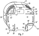
- Fig. 6 . 7 show an embodiment of a fan 10, which has a fastening device 26 for attachment to a DIN rail 1.
- the in connection with the Fig. 1-5 described design features and functions of the fastening device are also in connection with the fan according to Fig. 6 . 7 disclosed.
- the fan 10 has a nozzle 27.
- the nozzle 27 is a movable nozzle with which the direction of the air flow emerging from the fan nozzle 27 can be steered.
- the nozzle 27 is pivotable about an axis which in the fastened state runs parallel to the longitudinal axis of the DIN rail 1 (not shown).
- the nozzle 27 is fixed to a base plate 25.
- the connection between the nozzle 27 and the base plate 25 by a known per se one-dimensional pivot element or pivot joint (not shown).
- a one-dimensional pivoting element is pivotable in a single pivoting plane.
- the convexly curved rear wall of the nozzle 27 is accommodated in a correspondingly concavely curved front wall of the base plate 25.
- the side walls of the base plate 25 have louvers 30. Further louvers are provided in the front wall of the base plate 25 and in the rear wall of the nozzle 27.
- the rear wall of the base plate 25 has a fastening means 26 which allows the connection of the base plate 25 with a DIN rail 1 by a lateral tilting movement.
- the fastening device 26, as best in Fig. 7 see, upper and lower holding means 15 ', 15 "and 16', 16" on.
- the structure of the holding devices 15 ', 15 "and 16', 16" corresponds substantially to the structure of the holding device according to Fig. 1-5 to which reference is explicitly made at this point.
- the fan 10 according to Fig. 6 . 7 two upper holding devices 15 ', 15 "and two lower holding devices 16', 16" on.
- an upper holding device 15 'and a lower holding device 16' or 16 "cooperate in pairs for attaching the fan 10 to the mounting rail 1.
- the two upper holding devices 15 ', 15 are aligned at an angle of 90 ° to one another.
- Other alignment angles between the two upper holding devices 15 ', 15 "and the two lower holding devices 16', 16” are possible. This results in correspondingly different mounting positions.
- the alignment angle of the upper and lower holding means 15 ', 15 "and 16', 16" correspond to each other, so that the required for attachment to the DIN rail parallelism of the individual holding devices 15 ', 15 "or 16', 16" is maintained.
- the requirement of parallelism means that the two holding devices 15 ', 16' or 15 ", 16" of a holding pair run parallel to one another so that they can embrace the upper and lower edges 2, 3 of the DIN rail 1.
- the fan 27 comprises an exhaust grille 35, which is arranged on the rear wall 11 facing away from the fan 27. Through the exhaust grille 35, the air flows.
- the outlet grille 35 can be rotated about an axis that runs essentially parallel to the longitudinal axis of the fan 27. As a result, the outflow direction of the air can be changed or adjusted accordingly.
- the holding devices 15 ', 16' and 15 “, 16” are each a pair of holding in the mounted state in the longitudinal direction of the DIN rail offset from each other.
- This arrangement of the holding means 15 ', 16' and 15 “, 16” corresponds to that in the Fig. 1-5 detailed arrangement explained.
- the distance d between the respectively associated inner ends 17 ', 18' or 17 “, 18” of a holding pair is greater than the distance b between the upper edge 2 and the lower edge 3 of the DIN rail 1 (not shown).
- the fan 10 is tilted in a Einsetzkippraum k about a tilt axis Z perpendicular to Hutschienenlnatures X can be used in the top hat rail 1.
- the location of the aforementioned axes or directions is on the Fig. 1-5 directed.
- two locking latches 20 ', 20 are provided which enable the locking of the base plate 25 in the respectively selected position one of the two upper holding devices 15 ".
- the further locking bolt 20 ' is aligned with the other pair of holders and aligned with the corresponding other upper holding device 15'.
- the two locking latches 20 ', 20 "each have an oblique surface 21, along which the upper edge or lower edge 2, 3 of the DIN rail slides 1. Locking takes place along the retaining surface 24, which is located on the underside of the locking bolt 20' or 20 “is formed and in the fastened state engages over the upper edge or lower edge 2, 3.
- an actuating plate 23 is provided, which extends beyond the housing or the base plate 25 and is accessible from the side 2, 3 of the locking bar 20 ', 20 "and the associated holding surface 24 free. The fan can then be released from the DIN rail 1 by a tilting movement opposite to the insertion tilt direction k.
- the spring plate 22 is part of the rear wall 11 of the base plate 25, wherein the spring function is achieved by two parallel slots which separate the spring plate 22 in sections from the rear wall 11. The slots are parallel to the support surface 24th
- Figs. 8A and 8B show schematic side views of various types of DIN rails 1.
- the DIN rail 1 may have different formats.
- two common hat rail formats or types of top hat rails are used in switch cabinet construction.
- the DIN rail formats differ with regard to the depth of the DIN rail 1 and with respect to the Thickness, ie the diameter, of the material of the DIN rail 1 itself.
- Fig. 8A has the DIN rail 1 in comparison to the DIN rail 1 in Fig. 8B a greater depth (in Fig. 8A or. Fig. 8B this is the extension of the DIN rail 1 from left to right).
- the material of the hat rail 1 in Fig. 8B has a smaller diameter, ie a smaller thickness, compared to the DIN rail 1 in Fig. 8A ,
- the holding devices 15, 16 and in particular the chamfers 19, 19 ' are designed accordingly.
- the holding devices 15, 16 and / or the chamfers 19, 19 'of the fan 27 depending on which hat rail format or on which type of DIN rail 1, the fan 27 are fastened or fastened should be, appropriately trained or adapted.
Landscapes
- Engineering & Computer Science (AREA)
- Mechanical Engineering (AREA)
- General Engineering & Computer Science (AREA)
- Power Engineering (AREA)
- Microelectronics & Electronic Packaging (AREA)
- Physics & Mathematics (AREA)
- Thermal Sciences (AREA)
- Structures Of Non-Positive Displacement Pumps (AREA)
- Cooling Or The Like Of Electrical Apparatus (AREA)
- Mounting Components In General For Electric Apparatus (AREA)
Priority Applications (1)
| Application Number | Priority Date | Filing Date | Title |
|---|---|---|---|
| PL13704716T PL2812965T3 (pl) | 2012-02-07 | 2013-02-07 | Wentylator i układ zawierający wentylator |
Applications Claiming Priority (2)
| Application Number | Priority Date | Filing Date | Title |
|---|---|---|---|
| DE102012100974A DE102012100974B4 (de) | 2012-02-07 | 2012-02-07 | Lüfter und Anordnung aufweisend einen derartigen Lüfter |
| PCT/EP2013/000370 WO2013117338A1 (de) | 2012-02-07 | 2013-02-07 | Lüfter und anorndung aufweisend einen derartigen lüfter |
Publications (2)
| Publication Number | Publication Date |
|---|---|
| EP2812965A1 EP2812965A1 (de) | 2014-12-17 |
| EP2812965B1 true EP2812965B1 (de) | 2019-04-10 |
Family
ID=47722214
Family Applications (1)
| Application Number | Title | Priority Date | Filing Date |
|---|---|---|---|
| EP13704716.3A Active EP2812965B1 (de) | 2012-02-07 | 2013-02-07 | Lüfter und anordnung aufweisend einen derartigen lüfter |
Country Status (9)
| Country | Link |
|---|---|
| US (1) | US10202979B2 (pl) |
| EP (1) | EP2812965B1 (pl) |
| CN (1) | CN104106188B (pl) |
| DE (1) | DE102012100974B4 (pl) |
| ES (1) | ES2733749T3 (pl) |
| PL (1) | PL2812965T3 (pl) |
| RU (1) | RU2612648C2 (pl) |
| TR (1) | TR201909934T4 (pl) |
| WO (1) | WO2013117338A1 (pl) |
Families Citing this family (6)
| Publication number | Priority date | Publication date | Assignee | Title |
|---|---|---|---|---|
| USD730510S1 (en) | 2013-05-14 | 2015-05-26 | Stego-Holding Gmbh | Air vent |
| DE102014104857A1 (de) | 2014-04-04 | 2015-10-08 | Armin Meininger | Vorrichtung zur Klimatisierung elektronischer Baugruppen |
| DE102014017658A1 (de) * | 2014-11-24 | 2016-05-25 | Friedrich Lütze GmbH | Klimatisierungsanordnung |
| DE102014224989A1 (de) * | 2014-12-05 | 2016-06-09 | Siemens Aktiengesellschaft | Kühlvorrichtung zur Kühlung eines elektrischen Geräts |
| EP3282527A1 (de) | 2016-08-08 | 2018-02-14 | Siemens Aktiengesellschaft | Klimatisierung von elektrischen geräten mittels druckluft |
| CN108649465A (zh) * | 2018-06-29 | 2018-10-12 | 上海健康医学院 | 一种机电配电柜散热装置 |
Citations (2)
| Publication number | Priority date | Publication date | Assignee | Title |
|---|---|---|---|---|
| EP2118968A1 (en) * | 2007-03-08 | 2009-11-18 | Apollo Fire Detectors Limited | Electrical terminal block and method of fixture |
| DE102009014654A1 (de) * | 2009-03-25 | 2010-09-30 | Siemens Aktiengesellschaft | Lüftersystem für Stromverteileranlagen |
Family Cites Families (28)
| Publication number | Priority date | Publication date | Assignee | Title |
|---|---|---|---|---|
| USD338542S (en) | 1991-03-14 | 1993-08-17 | John Manufacturing Limited | Multi-purpose lantern |
| US5333787A (en) | 1992-02-05 | 1994-08-02 | Smith Leary W | Nozzle with self controlled oscillation |
| JPH07162167A (ja) * | 1993-12-06 | 1995-06-23 | Toyo Giken Kk | 電装体 |
| US5473824A (en) | 1994-03-21 | 1995-12-12 | Conair Corporation | Rotating outlet for hair dryers |
| US5522704A (en) * | 1994-10-27 | 1996-06-04 | Casteel; Mallard | Track mounted fan |
| USD375348S (en) | 1995-01-20 | 1996-11-05 | Sonja Varrigan | Heated air blower |
| US5640781A (en) * | 1995-02-07 | 1997-06-24 | Carson; Gary Patrick | Apparatus for styling natural and artificial hair |
| DE29517962U1 (de) * | 1995-11-13 | 1996-01-18 | Heinrich Kopp Ag, 63796 Kahl | Einrichtung zur Regelung der Temperatur für Schalt- und Verteilerschränke |
| US5839204A (en) | 1997-08-13 | 1998-11-24 | Cinque; Brenda A | Portable dryer with a retractable handle pitting into an indented housing |
| IT1318430B1 (it) | 2000-03-29 | 2003-08-25 | Mallinckrodt Holdings B V | Dispositivo per l'umidificazione passiva di pazienti tracheostomizzati o intubati. |
| CN2477877Y (zh) | 2001-03-22 | 2002-02-20 | 富准精密工业(深圳)有限公司 | 风扇固定装置 |
| JP2003283163A (ja) | 2002-03-20 | 2003-10-03 | Digital Electronics Corp | レール取付機構 |
| US20050092888A1 (en) * | 2003-11-03 | 2005-05-05 | Gonce Ken R. | Suspended ceiling fan |
| EP1542324A1 (de) * | 2003-12-12 | 2005-06-15 | HAGER ELECTRO GmbH | Lüftersystem für Stromverteileranlagen |
| US20050159101A1 (en) * | 2004-01-20 | 2005-07-21 | Hrdina Terry L. | Pivotal direct drive motor for exhaust assembly |
| USD538922S1 (en) | 2005-09-13 | 2007-03-20 | Smiths Group Plc | Airway heat and moisture exchanger |
| USD570981S1 (en) | 2006-04-28 | 2008-06-10 | Hewlett-Packard Development Company, L.P. | Fan module having a handle |
| ES2338260T3 (es) | 2006-07-13 | 2010-05-05 | Pfannenberg Gmbh | Dispositivo para paso de aire. |
| DE102007015470B4 (de) | 2007-03-30 | 2010-06-24 | Siemens Ag | Schnappbefestigung zur Befestigung eines Gehäuses |
| US8434238B2 (en) | 2007-06-29 | 2013-05-07 | Andis Company | Hair dryer with light source |
| JP4547636B2 (ja) * | 2008-02-25 | 2010-09-22 | 横河電機株式会社 | レール取付け型電子機器 |
| JP2009290018A (ja) * | 2008-05-29 | 2009-12-10 | Yamatake Corp | レール取付構造 |
| GB2476171B (en) * | 2009-03-04 | 2011-09-07 | Dyson Technology Ltd | Tilting fan stand |
| US8037619B2 (en) | 2009-04-28 | 2011-10-18 | Hokwang Industries Co., Ltd. | Air intake structure for hand dryers of high airflow pressure |
| USD610244S1 (en) | 2009-08-20 | 2010-02-16 | Gabbara Alan G | Vehicle drying apparatus |
| DE102010061555B3 (de) * | 2010-10-26 | 2012-04-26 | Stego-Holding Gmbh | Befestigungseinrichtung |
| USD670146S1 (en) | 2012-02-23 | 2012-11-06 | Bradford Coley | Heat gun for snow and ice |
| USD692111S1 (en) | 2012-10-11 | 2013-10-22 | Water Pik, Inc. | Mounting bracket for water flosser |
-
2012
- 2012-02-07 DE DE102012100974A patent/DE102012100974B4/de not_active Expired - Fee Related
-
2013
- 2013-02-07 RU RU2014136187A patent/RU2612648C2/ru active
- 2013-02-07 EP EP13704716.3A patent/EP2812965B1/de active Active
- 2013-02-07 ES ES13704716T patent/ES2733749T3/es active Active
- 2013-02-07 CN CN201380007930.3A patent/CN104106188B/zh not_active Expired - Fee Related
- 2013-02-07 TR TR2019/09934T patent/TR201909934T4/tr unknown
- 2013-02-07 US US14/377,371 patent/US10202979B2/en not_active Expired - Fee Related
- 2013-02-07 PL PL13704716T patent/PL2812965T3/pl unknown
- 2013-02-07 WO PCT/EP2013/000370 patent/WO2013117338A1/de not_active Ceased
Patent Citations (2)
| Publication number | Priority date | Publication date | Assignee | Title |
|---|---|---|---|---|
| EP2118968A1 (en) * | 2007-03-08 | 2009-11-18 | Apollo Fire Detectors Limited | Electrical terminal block and method of fixture |
| DE102009014654A1 (de) * | 2009-03-25 | 2010-09-30 | Siemens Aktiengesellschaft | Lüftersystem für Stromverteileranlagen |
Also Published As
| Publication number | Publication date |
|---|---|
| TR201909934T4 (tr) | 2019-07-22 |
| PL2812965T3 (pl) | 2019-09-30 |
| WO2013117338A1 (de) | 2013-08-15 |
| CN104106188A (zh) | 2014-10-15 |
| ES2733749T3 (es) | 2019-12-02 |
| US10202979B2 (en) | 2019-02-12 |
| RU2014136187A (ru) | 2016-04-10 |
| RU2612648C2 (ru) | 2017-03-13 |
| HK1201311A1 (en) | 2015-08-28 |
| WO2013117338A8 (de) | 2014-08-28 |
| CN104106188B (zh) | 2017-06-23 |
| EP2812965A1 (de) | 2014-12-17 |
| DE102012100974A1 (de) | 2013-08-08 |
| US20150016990A1 (en) | 2015-01-15 |
| DE102012100974B4 (de) | 2013-10-10 |
Similar Documents
| Publication | Publication Date | Title |
|---|---|---|
| EP2812965B1 (de) | Lüfter und anordnung aufweisend einen derartigen lüfter | |
| EP1890043B1 (de) | Luftdurchtrittsvorrichtung mit einer verbesserten Zugänglichkeit der Filtermatte | |
| EP2382905A2 (de) | Hohlprofil | |
| EP1331116B1 (de) | Luftdüse | |
| EP3257405A1 (de) | Winkelverstellbare konsole | |
| WO2021115656A1 (de) | Schiebe- und drehflügelsystem | |
| EP3997292A1 (de) | Scharnier und system zum lösbaren verbinden einer tür mit einem rahmen | |
| EP2951374B1 (de) | Laufteil zum führen eines möbelteils in einer führungsrichtung über eine führungsschiene und möbelbeschlag | |
| DE102017108957B3 (de) | Luftklappensystem mit Lamellenlagerstecksystem | |
| EP3009043B1 (de) | Schubkasten mit einer verstellvorrichtung für die ausrichtung der frontblende | |
| DE102010061555B3 (de) | Befestigungseinrichtung | |
| DE29807106U1 (de) | Elektrisches Installationsgerät, insbesondere zur Aufputz-Montage | |
| DE10124709B4 (de) | Front für Kraftfahrzeuge | |
| EP2842204A1 (de) | Befestigungseinrichtung sowie anordnung umfassend ein gerät oder einen körper und eine hutschiene | |
| DE29800086U1 (de) | Scharnier für klappbare oder schwenkbare Frontplatten | |
| EP0937596A1 (de) | Luftstromverteiler | |
| DE102005015222B3 (de) | Luftdüse | |
| DE102004013628A1 (de) | Schwenksitzanordnung für Fahrzeuge mit einer Crashsicherung | |
| EP4153017B1 (de) | Behälteraufnahmevorrichtung und halterung hierzu | |
| DE20112435U1 (de) | Punkthalter für Verbundsicherheitsglasplatte | |
| DE102005026016A1 (de) | Lautsprecher | |
| EP1410932B1 (de) | Luftdüse mit Befestigungsvorrichtung | |
| WO1998004859A1 (de) | Halterungsvorrichtung | |
| DE8527912U1 (de) | Luftauslaß | |
| DE69907996T2 (de) | Hakenvorrichtung zum Halten eines Flügels |
Legal Events
| Date | Code | Title | Description |
|---|---|---|---|
| PUAI | Public reference made under article 153(3) epc to a published international application that has entered the european phase |
Free format text: ORIGINAL CODE: 0009012 |
|
| 17P | Request for examination filed |
Effective date: 20140903 |
|
| AK | Designated contracting states |
Kind code of ref document: A1 Designated state(s): AL AT BE BG CH CY CZ DE DK EE ES FI FR GB GR HR HU IE IS IT LI LT LU LV MC MK MT NL NO PL PT RO RS SE SI SK SM TR |
|
| AX | Request for extension of the european patent |
Extension state: BA ME |
|
| DAX | Request for extension of the european patent (deleted) | ||
| REG | Reference to a national code |
Ref country code: HK Ref legal event code: DE Ref document number: 1201311 Country of ref document: HK |
|
| STAA | Information on the status of an ep patent application or granted ep patent |
Free format text: STATUS: EXAMINATION IS IN PROGRESS |
|
| 17Q | First examination report despatched |
Effective date: 20171017 |
|
| GRAP | Despatch of communication of intention to grant a patent |
Free format text: ORIGINAL CODE: EPIDOSNIGR1 |
|
| STAA | Information on the status of an ep patent application or granted ep patent |
Free format text: STATUS: GRANT OF PATENT IS INTENDED |
|
| RIC1 | Information provided on ipc code assigned before grant |
Ipc: F04D 25/08 20060101ALI20180928BHEP Ipc: F04D 19/00 20060101ALI20180928BHEP Ipc: H02B 1/052 20060101AFI20180928BHEP Ipc: F04D 29/60 20060101ALI20180928BHEP Ipc: H02B 1/56 20060101ALI20180928BHEP |
|
| INTG | Intention to grant announced |
Effective date: 20181015 |
|
| GRAS | Grant fee paid |
Free format text: ORIGINAL CODE: EPIDOSNIGR3 |
|
| GRAA | (expected) grant |
Free format text: ORIGINAL CODE: 0009210 |
|
| STAA | Information on the status of an ep patent application or granted ep patent |
Free format text: STATUS: THE PATENT HAS BEEN GRANTED |
|
| RBV | Designated contracting states (corrected) |
Designated state(s): AL AT BE BG CH CY CZ DK EE ES FI FR GB GR HR HU IE IS IT LI LT LU LV MC MK MT NL NO PL PT RO RS SE SI SK SM TR |
|
| REG | Reference to a national code |
Ref country code: DE Ref legal event code: R108 |
|
| AK | Designated contracting states |
Kind code of ref document: B1 Designated state(s): AL AT BE BG CH CY CZ DK EE ES FI FR GB GR HR HU IE IS IT LI LT LU LV MC MK MT NL NO PL PT RO RS SE SI SK SM TR |
|
| REG | Reference to a national code |
Ref country code: GB Ref legal event code: FG4D Free format text: NOT ENGLISH |
|
| REG | Reference to a national code |
Ref country code: CH Ref legal event code: EP Ref country code: AT Ref legal event code: REF Ref document number: 1119973 Country of ref document: AT Kind code of ref document: T Effective date: 20190415 |
|
| REG | Reference to a national code |
Ref country code: IE Ref legal event code: FG4D Free format text: LANGUAGE OF EP DOCUMENT: GERMAN |
|
| REG | Reference to a national code |
Ref country code: SE Ref legal event code: TRGR |
|
| REG | Reference to a national code |
Ref country code: NL Ref legal event code: FP |
|
| REG | Reference to a national code |
Ref country code: LT Ref legal event code: MG4D |
|
| PG25 | Lapsed in a contracting state [announced via postgrant information from national office to epo] |
Ref country code: AL Free format text: LAPSE BECAUSE OF FAILURE TO SUBMIT A TRANSLATION OF THE DESCRIPTION OR TO PAY THE FEE WITHIN THE PRESCRIBED TIME-LIMIT Effective date: 20190410 Ref country code: NO Free format text: LAPSE BECAUSE OF FAILURE TO SUBMIT A TRANSLATION OF THE DESCRIPTION OR TO PAY THE FEE WITHIN THE PRESCRIBED TIME-LIMIT Effective date: 20190710 Ref country code: FI Free format text: LAPSE BECAUSE OF FAILURE TO SUBMIT A TRANSLATION OF THE DESCRIPTION OR TO PAY THE FEE WITHIN THE PRESCRIBED TIME-LIMIT Effective date: 20190410 Ref country code: PT Free format text: LAPSE BECAUSE OF FAILURE TO SUBMIT A TRANSLATION OF THE DESCRIPTION OR TO PAY THE FEE WITHIN THE PRESCRIBED TIME-LIMIT Effective date: 20190910 Ref country code: LT Free format text: LAPSE BECAUSE OF FAILURE TO SUBMIT A TRANSLATION OF THE DESCRIPTION OR TO PAY THE FEE WITHIN THE PRESCRIBED TIME-LIMIT Effective date: 20190410 Ref country code: HR Free format text: LAPSE BECAUSE OF FAILURE TO SUBMIT A TRANSLATION OF THE DESCRIPTION OR TO PAY THE FEE WITHIN THE PRESCRIBED TIME-LIMIT Effective date: 20190410 |
|
| PG25 | Lapsed in a contracting state [announced via postgrant information from national office to epo] |
Ref country code: GR Free format text: LAPSE BECAUSE OF FAILURE TO SUBMIT A TRANSLATION OF THE DESCRIPTION OR TO PAY THE FEE WITHIN THE PRESCRIBED TIME-LIMIT Effective date: 20190711 Ref country code: BG Free format text: LAPSE BECAUSE OF FAILURE TO SUBMIT A TRANSLATION OF THE DESCRIPTION OR TO PAY THE FEE WITHIN THE PRESCRIBED TIME-LIMIT Effective date: 20190710 Ref country code: LV Free format text: LAPSE BECAUSE OF FAILURE TO SUBMIT A TRANSLATION OF THE DESCRIPTION OR TO PAY THE FEE WITHIN THE PRESCRIBED TIME-LIMIT Effective date: 20190410 Ref country code: RS Free format text: LAPSE BECAUSE OF FAILURE TO SUBMIT A TRANSLATION OF THE DESCRIPTION OR TO PAY THE FEE WITHIN THE PRESCRIBED TIME-LIMIT Effective date: 20190410 |
|
| REG | Reference to a national code |
Ref country code: ES Ref legal event code: FG2A Ref document number: 2733749 Country of ref document: ES Kind code of ref document: T3 Effective date: 20191202 |
|
| PG25 | Lapsed in a contracting state [announced via postgrant information from national office to epo] |
Ref country code: IS Free format text: LAPSE BECAUSE OF FAILURE TO SUBMIT A TRANSLATION OF THE DESCRIPTION OR TO PAY THE FEE WITHIN THE PRESCRIBED TIME-LIMIT Effective date: 20190810 |
|
| PG25 | Lapsed in a contracting state [announced via postgrant information from national office to epo] |
Ref country code: DK Free format text: LAPSE BECAUSE OF FAILURE TO SUBMIT A TRANSLATION OF THE DESCRIPTION OR TO PAY THE FEE WITHIN THE PRESCRIBED TIME-LIMIT Effective date: 20190410 Ref country code: EE Free format text: LAPSE BECAUSE OF FAILURE TO SUBMIT A TRANSLATION OF THE DESCRIPTION OR TO PAY THE FEE WITHIN THE PRESCRIBED TIME-LIMIT Effective date: 20190410 Ref country code: RO Free format text: LAPSE BECAUSE OF FAILURE TO SUBMIT A TRANSLATION OF THE DESCRIPTION OR TO PAY THE FEE WITHIN THE PRESCRIBED TIME-LIMIT Effective date: 20190410 Ref country code: CZ Free format text: LAPSE BECAUSE OF FAILURE TO SUBMIT A TRANSLATION OF THE DESCRIPTION OR TO PAY THE FEE WITHIN THE PRESCRIBED TIME-LIMIT Effective date: 20190410 Ref country code: SK Free format text: LAPSE BECAUSE OF FAILURE TO SUBMIT A TRANSLATION OF THE DESCRIPTION OR TO PAY THE FEE WITHIN THE PRESCRIBED TIME-LIMIT Effective date: 20190410 |
|
| PLBE | No opposition filed within time limit |
Free format text: ORIGINAL CODE: 0009261 |
|
| STAA | Information on the status of an ep patent application or granted ep patent |
Free format text: STATUS: NO OPPOSITION FILED WITHIN TIME LIMIT |
|
| PG25 | Lapsed in a contracting state [announced via postgrant information from national office to epo] |
Ref country code: SM Free format text: LAPSE BECAUSE OF FAILURE TO SUBMIT A TRANSLATION OF THE DESCRIPTION OR TO PAY THE FEE WITHIN THE PRESCRIBED TIME-LIMIT Effective date: 20190410 |
|
| 26N | No opposition filed |
Effective date: 20200113 |
|
| PG25 | Lapsed in a contracting state [announced via postgrant information from national office to epo] |
Ref country code: SI Free format text: LAPSE BECAUSE OF FAILURE TO SUBMIT A TRANSLATION OF THE DESCRIPTION OR TO PAY THE FEE WITHIN THE PRESCRIBED TIME-LIMIT Effective date: 20190410 |
|
| REG | Reference to a national code |
Ref country code: CH Ref legal event code: PL |
|
| REG | Reference to a national code |
Ref country code: BE Ref legal event code: MM Effective date: 20200229 |
|
| PG25 | Lapsed in a contracting state [announced via postgrant information from national office to epo] |
Ref country code: MC Free format text: LAPSE BECAUSE OF FAILURE TO SUBMIT A TRANSLATION OF THE DESCRIPTION OR TO PAY THE FEE WITHIN THE PRESCRIBED TIME-LIMIT Effective date: 20190410 Ref country code: LU Free format text: LAPSE BECAUSE OF NON-PAYMENT OF DUE FEES Effective date: 20200207 |
|
| PG25 | Lapsed in a contracting state [announced via postgrant information from national office to epo] |
Ref country code: LI Free format text: LAPSE BECAUSE OF NON-PAYMENT OF DUE FEES Effective date: 20200229 Ref country code: CH Free format text: LAPSE BECAUSE OF NON-PAYMENT OF DUE FEES Effective date: 20200229 |
|
| PG25 | Lapsed in a contracting state [announced via postgrant information from national office to epo] |
Ref country code: IE Free format text: LAPSE BECAUSE OF NON-PAYMENT OF DUE FEES Effective date: 20200207 |
|
| PG25 | Lapsed in a contracting state [announced via postgrant information from national office to epo] |
Ref country code: BE Free format text: LAPSE BECAUSE OF NON-PAYMENT OF DUE FEES Effective date: 20200229 |
|
| REG | Reference to a national code |
Ref country code: AT Ref legal event code: MM01 Ref document number: 1119973 Country of ref document: AT Kind code of ref document: T Effective date: 20200207 |
|
| PGFP | Annual fee paid to national office [announced via postgrant information from national office to epo] |
Ref country code: NL Payment date: 20210223 Year of fee payment: 9 Ref country code: IT Payment date: 20210223 Year of fee payment: 9 Ref country code: CZ Payment date: 20210205 Year of fee payment: 9 Ref country code: FR Payment date: 20210223 Year of fee payment: 9 |
|
| PG25 | Lapsed in a contracting state [announced via postgrant information from national office to epo] |
Ref country code: AT Free format text: LAPSE BECAUSE OF NON-PAYMENT OF DUE FEES Effective date: 20200207 |
|
| PGFP | Annual fee paid to national office [announced via postgrant information from national office to epo] |
Ref country code: ES Payment date: 20210316 Year of fee payment: 9 Ref country code: GB Payment date: 20210223 Year of fee payment: 9 Ref country code: PL Payment date: 20210114 Year of fee payment: 9 Ref country code: SE Payment date: 20210219 Year of fee payment: 9 |
|
| PG25 | Lapsed in a contracting state [announced via postgrant information from national office to epo] |
Ref country code: MT Free format text: LAPSE BECAUSE OF FAILURE TO SUBMIT A TRANSLATION OF THE DESCRIPTION OR TO PAY THE FEE WITHIN THE PRESCRIBED TIME-LIMIT Effective date: 20190410 Ref country code: CY Free format text: LAPSE BECAUSE OF FAILURE TO SUBMIT A TRANSLATION OF THE DESCRIPTION OR TO PAY THE FEE WITHIN THE PRESCRIBED TIME-LIMIT Effective date: 20190410 |
|
| PG25 | Lapsed in a contracting state [announced via postgrant information from national office to epo] |
Ref country code: MK Free format text: LAPSE BECAUSE OF FAILURE TO SUBMIT A TRANSLATION OF THE DESCRIPTION OR TO PAY THE FEE WITHIN THE PRESCRIBED TIME-LIMIT Effective date: 20190410 |
|
| REG | Reference to a national code |
Ref country code: SE Ref legal event code: EUG |
|
| REG | Reference to a national code |
Ref country code: NL Ref legal event code: MM Effective date: 20220301 |
|
| GBPC | Gb: european patent ceased through non-payment of renewal fee |
Effective date: 20220207 |
|
| PG25 | Lapsed in a contracting state [announced via postgrant information from national office to epo] |
Ref country code: SE Free format text: LAPSE BECAUSE OF NON-PAYMENT OF DUE FEES Effective date: 20220208 Ref country code: CZ Free format text: LAPSE BECAUSE OF NON-PAYMENT OF DUE FEES Effective date: 20220207 |
|
| PG25 | Lapsed in a contracting state [announced via postgrant information from national office to epo] |
Ref country code: NL Free format text: LAPSE BECAUSE OF NON-PAYMENT OF DUE FEES Effective date: 20220301 Ref country code: FR Free format text: LAPSE BECAUSE OF NON-PAYMENT OF DUE FEES Effective date: 20220228 |
|
| PG25 | Lapsed in a contracting state [announced via postgrant information from national office to epo] |
Ref country code: GB Free format text: LAPSE BECAUSE OF NON-PAYMENT OF DUE FEES Effective date: 20220207 |
|
| REG | Reference to a national code |
Ref country code: ES Ref legal event code: FD2A Effective date: 20230428 |
|
| PG25 | Lapsed in a contracting state [announced via postgrant information from national office to epo] |
Ref country code: IT Free format text: LAPSE BECAUSE OF NON-PAYMENT OF DUE FEES Effective date: 20220207 |
|
| P01 | Opt-out of the competence of the unified patent court (upc) registered |
Effective date: 20230602 |
|
| PG25 | Lapsed in a contracting state [announced via postgrant information from national office to epo] |
Ref country code: ES Free format text: LAPSE BECAUSE OF NON-PAYMENT OF DUE FEES Effective date: 20220208 |
|
| PG25 | Lapsed in a contracting state [announced via postgrant information from national office to epo] |
Ref country code: TR Free format text: LAPSE BECAUSE OF NON-PAYMENT OF DUE FEES Effective date: 20200207 |
|
| PG25 | Lapsed in a contracting state [announced via postgrant information from national office to epo] |
Ref country code: PL Free format text: LAPSE BECAUSE OF NON-PAYMENT OF DUE FEES Effective date: 20220207 |
|
| PG25 | Lapsed in a contracting state [announced via postgrant information from national office to epo] |
Ref country code: PL Free format text: LAPSE BECAUSE OF NON-PAYMENT OF DUE FEES Effective date: 20220207 |