EP2811555B1 - Method of preparation for precursor particles of lithium composite transition metal oxide using a rotating reactor - Google Patents
Method of preparation for precursor particles of lithium composite transition metal oxide using a rotating reactor Download PDFInfo
- Publication number
- EP2811555B1 EP2811555B1 EP13743401.5A EP13743401A EP2811555B1 EP 2811555 B1 EP2811555 B1 EP 2811555B1 EP 13743401 A EP13743401 A EP 13743401A EP 2811555 B1 EP2811555 B1 EP 2811555B1
- Authority
- EP
- European Patent Office
- Prior art keywords
- transition metal
- rotating
- composite transition
- metal hydroxide
- reactor
- Prior art date
- Legal status (The legal status is an assumption and is not a legal conclusion. Google has not performed a legal analysis and makes no representation as to the accuracy of the status listed.)
- Active
Links
Images


Classifications
-
- H—ELECTRICITY
- H01—ELECTRIC ELEMENTS
- H01M—PROCESSES OR MEANS, e.g. BATTERIES, FOR THE DIRECT CONVERSION OF CHEMICAL ENERGY INTO ELECTRICAL ENERGY
- H01M4/00—Electrodes
- H01M4/02—Electrodes composed of, or comprising, active material
- H01M4/36—Selection of substances as active materials, active masses, active liquids
- H01M4/48—Selection of substances as active materials, active masses, active liquids of inorganic oxides or hydroxides
- H01M4/485—Selection of substances as active materials, active masses, active liquids of inorganic oxides or hydroxides of mixed oxides or hydroxides for inserting or intercalating light metals, e.g. LiTi2O4 or LiTi2OxFy
-
- H—ELECTRICITY
- H01—ELECTRIC ELEMENTS
- H01M—PROCESSES OR MEANS, e.g. BATTERIES, FOR THE DIRECT CONVERSION OF CHEMICAL ENERGY INTO ELECTRICAL ENERGY
- H01M4/00—Electrodes
- H01M4/02—Electrodes composed of, or comprising, active material
- H01M4/36—Selection of substances as active materials, active masses, active liquids
- H01M4/48—Selection of substances as active materials, active masses, active liquids of inorganic oxides or hydroxides
-
- C—CHEMISTRY; METALLURGY
- C01—INORGANIC CHEMISTRY
- C01G—COMPOUNDS CONTAINING METALS NOT COVERED BY SUBCLASSES C01D OR C01F
- C01G53/00—Compounds of nickel
- C01G53/40—Complex oxides containing nickel and at least one other metal element
- C01G53/42—Complex oxides containing nickel and at least one other metal element containing alkali metals, e.g. LiNiO2
- C01G53/44—Complex oxides containing nickel and at least one other metal element containing alkali metals, e.g. LiNiO2 containing manganese
- C01G53/50—Complex oxides containing nickel and at least one other metal element containing alkali metals, e.g. LiNiO2 containing manganese of the type (MnO2)n-, e.g. Li(NixMn1-x)O2 or Li(MyNixMn1-x-y)O2
-
- H—ELECTRICITY
- H01—ELECTRIC ELEMENTS
- H01M—PROCESSES OR MEANS, e.g. BATTERIES, FOR THE DIRECT CONVERSION OF CHEMICAL ENERGY INTO ELECTRICAL ENERGY
- H01M4/00—Electrodes
- H01M4/02—Electrodes composed of, or comprising, active material
- H01M4/13—Electrodes for accumulators with non-aqueous electrolyte, e.g. for lithium-accumulators; Processes of manufacture thereof
- H01M4/131—Electrodes based on mixed oxides or hydroxides, or on mixtures of oxides or hydroxides, e.g. LiCoOx
-
- H—ELECTRICITY
- H01—ELECTRIC ELEMENTS
- H01M—PROCESSES OR MEANS, e.g. BATTERIES, FOR THE DIRECT CONVERSION OF CHEMICAL ENERGY INTO ELECTRICAL ENERGY
- H01M4/00—Electrodes
- H01M4/02—Electrodes composed of, or comprising, active material
- H01M4/36—Selection of substances as active materials, active masses, active liquids
- H01M4/48—Selection of substances as active materials, active masses, active liquids of inorganic oxides or hydroxides
- H01M4/50—Selection of substances as active materials, active masses, active liquids of inorganic oxides or hydroxides of manganese
- H01M4/505—Selection of substances as active materials, active masses, active liquids of inorganic oxides or hydroxides of manganese of mixed oxides or hydroxides containing manganese for inserting or intercalating light metals, e.g. LiMn2O4 or LiMn2OxFy
-
- H—ELECTRICITY
- H01—ELECTRIC ELEMENTS
- H01M—PROCESSES OR MEANS, e.g. BATTERIES, FOR THE DIRECT CONVERSION OF CHEMICAL ENERGY INTO ELECTRICAL ENERGY
- H01M4/00—Electrodes
- H01M4/02—Electrodes composed of, or comprising, active material
- H01M4/36—Selection of substances as active materials, active masses, active liquids
- H01M4/48—Selection of substances as active materials, active masses, active liquids of inorganic oxides or hydroxides
- H01M4/52—Selection of substances as active materials, active masses, active liquids of inorganic oxides or hydroxides of nickel, cobalt or iron
- H01M4/525—Selection of substances as active materials, active masses, active liquids of inorganic oxides or hydroxides of nickel, cobalt or iron of mixed oxides or hydroxides containing iron, cobalt or nickel for inserting or intercalating light metals, e.g. LiNiO2, LiCoO2 or LiCoOxFy
-
- C—CHEMISTRY; METALLURGY
- C01—INORGANIC CHEMISTRY
- C01G—COMPOUNDS CONTAINING METALS NOT COVERED BY SUBCLASSES C01D OR C01F
- C01G51/00—Compounds of cobalt
- C01G51/04—Oxides
-
- C—CHEMISTRY; METALLURGY
- C01—INORGANIC CHEMISTRY
- C01G—COMPOUNDS CONTAINING METALS NOT COVERED BY SUBCLASSES C01D OR C01F
- C01G51/00—Compounds of cobalt
- C01G51/40—Complex oxides containing cobalt and at least one other metal element
- C01G51/42—Complex oxides containing cobalt and at least one other metal element containing alkali metals, e.g. LiCoO2
- C01G51/44—Complex oxides containing cobalt and at least one other metal element containing alkali metals, e.g. LiCoO2 containing manganese
-
- C—CHEMISTRY; METALLURGY
- C01—INORGANIC CHEMISTRY
- C01G—COMPOUNDS CONTAINING METALS NOT COVERED BY SUBCLASSES C01D OR C01F
- C01G53/00—Compounds of nickel
- C01G53/04—Oxides
-
- C—CHEMISTRY; METALLURGY
- C01—INORGANIC CHEMISTRY
- C01P—INDEXING SCHEME RELATING TO STRUCTURAL AND PHYSICAL ASPECTS OF SOLID INORGANIC COMPOUNDS
- C01P2004/00—Particle morphology
- C01P2004/01—Particle morphology depicted by an image
- C01P2004/03—Particle morphology depicted by an image obtained by SEM
-
- C—CHEMISTRY; METALLURGY
- C01—INORGANIC CHEMISTRY
- C01P—INDEXING SCHEME RELATING TO STRUCTURAL AND PHYSICAL ASPECTS OF SOLID INORGANIC COMPOUNDS
- C01P2004/00—Particle morphology
- C01P2004/60—Particles characterised by their size
- C01P2004/61—Micrometer sized, i.e. from 1-100 micrometer
-
- C—CHEMISTRY; METALLURGY
- C01—INORGANIC CHEMISTRY
- C01P—INDEXING SCHEME RELATING TO STRUCTURAL AND PHYSICAL ASPECTS OF SOLID INORGANIC COMPOUNDS
- C01P2006/00—Physical properties of inorganic compounds
- C01P2006/40—Electric properties
-
- H—ELECTRICITY
- H01—ELECTRIC ELEMENTS
- H01M—PROCESSES OR MEANS, e.g. BATTERIES, FOR THE DIRECT CONVERSION OF CHEMICAL ENERGY INTO ELECTRICAL ENERGY
- H01M10/00—Secondary cells; Manufacture thereof
- H01M10/05—Accumulators with non-aqueous electrolyte
- H01M10/052—Li-accumulators
-
- H—ELECTRICITY
- H01—ELECTRIC ELEMENTS
- H01M—PROCESSES OR MEANS, e.g. BATTERIES, FOR THE DIRECT CONVERSION OF CHEMICAL ENERGY INTO ELECTRICAL ENERGY
- H01M4/00—Electrodes
- H01M4/02—Electrodes composed of, or comprising, active material
- H01M4/36—Selection of substances as active materials, active masses, active liquids
- H01M4/48—Selection of substances as active materials, active masses, active liquids of inorganic oxides or hydroxides
- H01M4/50—Selection of substances as active materials, active masses, active liquids of inorganic oxides or hydroxides of manganese
-
- H—ELECTRICITY
- H01—ELECTRIC ELEMENTS
- H01M—PROCESSES OR MEANS, e.g. BATTERIES, FOR THE DIRECT CONVERSION OF CHEMICAL ENERGY INTO ELECTRICAL ENERGY
- H01M4/00—Electrodes
- H01M4/02—Electrodes composed of, or comprising, active material
- H01M4/36—Selection of substances as active materials, active masses, active liquids
- H01M4/48—Selection of substances as active materials, active masses, active liquids of inorganic oxides or hydroxides
- H01M4/52—Selection of substances as active materials, active masses, active liquids of inorganic oxides or hydroxides of nickel, cobalt or iron
-
- Y—GENERAL TAGGING OF NEW TECHNOLOGICAL DEVELOPMENTS; GENERAL TAGGING OF CROSS-SECTIONAL TECHNOLOGIES SPANNING OVER SEVERAL SECTIONS OF THE IPC; TECHNICAL SUBJECTS COVERED BY FORMER USPC CROSS-REFERENCE ART COLLECTIONS [XRACs] AND DIGESTS
- Y02—TECHNOLOGIES OR APPLICATIONS FOR MITIGATION OR ADAPTATION AGAINST CLIMATE CHANGE
- Y02E—REDUCTION OF GREENHOUSE GAS [GHG] EMISSIONS, RELATED TO ENERGY GENERATION, TRANSMISSION OR DISTRIBUTION
- Y02E60/00—Enabling technologies; Technologies with a potential or indirect contribution to GHG emissions mitigation
- Y02E60/10—Energy storage using batteries
-
- Y—GENERAL TAGGING OF NEW TECHNOLOGICAL DEVELOPMENTS; GENERAL TAGGING OF CROSS-SECTIONAL TECHNOLOGIES SPANNING OVER SEVERAL SECTIONS OF THE IPC; TECHNICAL SUBJECTS COVERED BY FORMER USPC CROSS-REFERENCE ART COLLECTIONS [XRACs] AND DIGESTS
- Y02—TECHNOLOGIES OR APPLICATIONS FOR MITIGATION OR ADAPTATION AGAINST CLIMATE CHANGE
- Y02P—CLIMATE CHANGE MITIGATION TECHNOLOGIES IN THE PRODUCTION OR PROCESSING OF GOODS
- Y02P70/00—Climate change mitigation technologies in the production process for final industrial or consumer products
- Y02P70/50—Manufacturing or production processes characterised by the final manufactured product
-
- Y—GENERAL TAGGING OF NEW TECHNOLOGICAL DEVELOPMENTS; GENERAL TAGGING OF CROSS-SECTIONAL TECHNOLOGIES SPANNING OVER SEVERAL SECTIONS OF THE IPC; TECHNICAL SUBJECTS COVERED BY FORMER USPC CROSS-REFERENCE ART COLLECTIONS [XRACs] AND DIGESTS
- Y02—TECHNOLOGIES OR APPLICATIONS FOR MITIGATION OR ADAPTATION AGAINST CLIMATE CHANGE
- Y02T—CLIMATE CHANGE MITIGATION TECHNOLOGIES RELATED TO TRANSPORTATION
- Y02T10/00—Road transport of goods or passengers
- Y02T10/60—Other road transportation technologies with climate change mitigation effect
- Y02T10/70—Energy storage systems for electromobility, e.g. batteries
Definitions
- the present invention relates to a method for preparing precursor particles of a lithium composite transition metal oxide for lithium secondary batteries, wherein the precursor particles of a lithium composite transition metal oxide are composite transition metal hydroxide particles including at least two transition metals and having an average diameter of 1 ⁇ m to 5 ⁇ m, wherein the composite transition metal hydroxide particles exhibit monodisperse particle size distribution and have a coefficient of variation of 0.2 to 0.7.
- lithium secondary batteries which exhibit high energy density and voltage and have long cycle lifespan and low selfdischarge rate, are commercially available and widely used.
- cathode active materials play a critical role in determining battery capacity and performance.
- lithium cobalt oxides e.g., LiCoO 2
- LiCoO 2 lithium cobalt oxides having relatively excellent physical properties, such as excellent cycle characteristics and the like
- cobalt used in LiCoO 2 is a rare metal and supply of cobalt is unstable because reserves and production thereof are limited.
- LiCoO 2 is expensive due to unstable supply of cobalt and increasing demand for lithium secondary batteries.
- lithium composite transition metal oxides including at least two transition metals selected from among nickel (Ni), manganese (Mn), and cobalt (Co) may be used.
- Such lithium composite transition metal oxides exhibit excellent electrochemical properties through combination of high capacity of a lithium nickel oxide (e.g., LiNiO 2 ), thermal stability and low price of Mn in a lithium manganese oxide (e.g., LiMnO 2 ) having a layered structure, and stable electrochemical properties of LiCoO 2 .
- a lithium nickel oxide e.g., LiNiO 2
- thermal stability and low price of Mn in a lithium manganese oxide e.g., LiMnO 2
- LiMnO 2 lithium manganese oxide having a layered structure
- lithium composite transition metal oxides are prepared by separately preparing a composite transition metal precursor including at least two transition metals selected from among Ni, Mn, and Co by a sol-gel method, a hydrothermal method, spray pyrolysis, co-precipitation, or the like, mixing the composite transition metal precursor with a lithium precursor, and calcining the resulting mixture at high temperature, as in JP 4840545 B 1 and JP 2010 070431 A .
- a composite transition metal precursor is generally prepared by co-precipitation in consideration of cost, productivity, and the like.
- conventional composite transition metal precursor particles prepared by co-precipitation have a minimum average diameter of 6 ⁇ m to 10 ⁇ m.
- the present invention aims to address the aforementioned problems of the related art and to achieve technical goals that have long been sought.
- the object of the present invention is to provide a method for preparing composite transition metal precursor particles having excellent and uniform size and high crystallinity when compared to conventional composite transition metal precursors.
- the present invention relates to a method for preparing transition metal composite hydroxide particles using a reactor having a closed structure including:
- the present invention relates to a method for preparing precursor particles of a lithium composite transition metal oxide for lithium secondary batteries, wherein the precursor particles are composite transition metal hydroxide particles including at least two transition metals and having an average diameter of 1 ⁇ m to 5 ⁇ m, wherein the composite transition metal hydroxide particles exhibit monodisperse particle size distribution in which a parameter that represents particle size distribution is not limited and, when the particle size distribution is represented as a coefficient of variation, the coefficient of variation is in the range of 0.2 to 0.7.
- the coefficient of variation is a value obtained by dividing standard deviation by mass median diameter D50.
- the composite transition metal hydroxide particles prepared by the method of the present invention have a minimum average diameter of 1 ⁇ m to 5 ⁇ m.
- the composite transition metal hydroxide particles prepared according to the method of the present invention exhibit monodisperse particle size distribution as compared to conventional composite transition metal hydroxide particles having a coefficient of variation of 0.2 to 0.7.
- the precursor particles prepared by the method of the present invention have smaller monodisperse particle size than conventional transition metal precursor particles and thus movement distance of lithium ions decreases during charge and discharge and, accordingly, rate characteristics are enhanced.
- such enhancement effects are more significantly exhibited in terms of low-temperature rate characteristics and, when the precursor particles are added together with existing large precursor particles, electrode packing density increases.
- the composite transition metal hydroxide may be a compound represented by Formula 1 below: M(OH 1-x ) 2 (1) wherein M is at least two selected from the group consisting of nickel (Ni), cobalt (Co), manganese (Mn), aluminum (Al), copper (Cu), iron (Fe), magnesium (Mg), boron (B), chromium (Cr), and period 2 transition metals; and 0 ⁇ x ⁇ 0.8.
- M represents two or more selected from among the abovedefined elements.
- M is at least one transition metal selected from the group consisting of Ni, Co, and Mn and thus physical properties of at least one of the transition metals may be exhibited in the lithium composite transition metal oxide. More preferably, M may represent two transition metals selected from the group consisting of Ni, Co, and Mn or all thereof.
- the compound of Formula 1 may be a compound represented by Formula 2 below: Ni b Mn c Co 1-(b+c+d) M" d (OH 1-x ) 2 (2) wherein 0.3 ⁇ b ⁇ 0.9, 0.1 ⁇ c ⁇ 0.6, 0 ⁇ d ⁇ 0.1, b+c+d ⁇ 1, 0 ⁇ x ⁇ 0.8, and M" is at least one selected from the group consisting of Al, Mg, Cr, titanium (Ti), and silicon (Si). That is, the compound of Formula 1 may be the compound of Formula 2 where M represents all of Ni, Co, and Mn, which are partially substituted with at least one selected from the group consisting of Al, Mg, Cr, Ti, and Si.
- the compound of Formula 2 includes a high content of Ni and thus may be used to prepare a cathode active material for high-capacity lithium secondary batteries.
- the composite transition metal hydroxide particles prepared according to the method of the present invention exhibit higher crystallinity than conventional transition metal precursors.
- the crystallinity may be determined by the amount of impurities derived from a transition metal salt for preparation of a composite transition metal hydroxide.
- the composite transition metal hydroxide particles prepared according to the method of the present invention include 0.4 wt% or less, particularly 0.3 wt% to 0.4 wt%, of impurities derived from a transition metal salt for preparation of a composite transition metal hydroxide based on a total weight of the composite transition metal hydroxide particles.
- the impurities may be salt ions including sulfate ions (SO 4 2- ).
- a transition metal salt from which the salt ions including sulfate ions (SO 4 2- ) are derived may be a sulfate and the sulfate may, for example, be nickel sulfate, cobalt sulfate, manganese sulfate, or the like. These sulfates may be used alone or at least two thereof may be used in combination.
- the salt ions including sulfate ions (SO 4 2- ) may further include nitrate ions (NO 3 - ), and the nitrate ions may be derived from a transition metal salt such as nickel nitrate, cobalt nitrate, manganese nitrate, or the like.
- the amount of the salt ions including sulfate ions (SO 4 2- ) may be 0.3 wt% to 0.4 wt% based on the total weight of the composite transition metal hydroxide particles.
- the amount of the salt ions in the precursor particles may be measured using various methods, preferably by ion chromatography.
- a lithium composite transition metal oxide can be prepared through calcination reaction between the transition metal precursor particles and a lithium precursor.
- Reaction conditions of a transition metal precursor and a lithium-containing material to prepare a lithium composite transition metal oxide are known in the art and thus a detailed description thereof will be omitted herein.
- the lithium precursor is not particularly limited and may, for example, be lithium hydroxide, lithium carbonate, lithium oxide, or the like. Particularly, the lithium precursor may be lithium carbonate (Li 2 CO 3 ) and/or lithium hydroxide ((LiOH).
- the lithium composite transition metal oxide particles prepared include at least two transition metals and have an average diameter of 1.0 ⁇ m to 8.5 ⁇ m, preferably of 1.0 ⁇ m to 5.5 ⁇ m.
- the lithium composite transition metal oxide particles exhibit monodisperse particle size distribution and have a coefficient of variation of 0.2 to 0.7.
- the composite transition metal hydroxide particles are prepared by introducing, into a rotating reaction space of a reactor, an aqueous solution of raw materials including an aqueous solution of at least two transition metal salts and a basic aqueous solution so as to maintain pH of the aqueous solution of raw materials at a constant level of 10 to 12 via an inlet of the reactor and performing co-precipitation thereof in a non-nitrogen atmosphere for 1 to 6 hours.
- the composite transition metal hydroxide particles may be obtained via an outlet.
- the reactor has a closed structure including: a hollow fixed cylinder;
- the composite transition metal hydroxide is prepared using a conventional co-precipitation reactor, e.g., a continuous stirred tank reactor (CSTR), a residence time of approximately 6 hours or longer is needed.
- a conventional co-precipitation reactor e.g., a continuous stirred tank reactor (CSTR)
- CSTR continuous stirred tank reactor
- Such effects are obtained when a ratio of a distance between the fixed cylinder and the rotating cylinder to an outer radius of the rotating cylinder exceeds 0.05.
- the ratio of the distance between the fixed cylinder and the rotating cylinder to the outer radius of the rotating cylinder is 0.05 or less, the distance between the fixed cylinder and the rotating cylinder is too small and thus it is impossible to constitute the elements.
- one vortex pair substantially acts as a single fine CSTR and thus the vortex pairs periodically arranged along a rotating shaft act as fine CSTRs connected to one another. As the number of the vortex pairs increases, flow characteristics are enhanced.
- the size of the vortex pair is nearly similar to the distance between the fixed cylinder and the rotating cylinder and thus, as the ratio of the distance between the fixed cylinder and the rotating cylinder to the outer radius of the rotating cylinder increases or as the distance between the fixed cylinder and the rotating cylinder increases, the number of the vortex pairs in the reactor (the number of CSTRs) gradually decreases.
- characteristics of continuous vortex such as the ring-shaped vortex pairs (laminar vortex) periodically arranged along the rotating axis and rotating in opposite directions according to increase in rotation rate of the rotating cylinder, wavy vortex, modulated wavy vortex, and turbulent vortex, are not exhibited and transition from a laminar vortex region to a turbulent vortex region occurs right away, and thus, flow characteristics of the vortex pairs are deteriorated and, accordingly, it is difficult to prepare uniform precursor particles exhibiting small particle size distribution and having a small average diameter.
- the composite transition metal hydroxide particles prepared using the above-mentioned reactor may be prepared as uniform transition metal precursor particles exhibiting smaller particle size distribution and having a smaller average diameter than composite transition metal hydroxide particles prepared using a CSTR.
- control of such particle size distribution and average particle diameter may be implemented in a case in which the ratio of the distance between the fixed cylinder and the rotating cylinder to the outer radius of the rotating cylinder is less than 0.4.
- the ratio of the distance between the fixed cylinder and the rotating cylinder to the outer radius of the rotating cylinder is greater than 0.05 to less than 0.4.
- the reactor is optimized to prepare composite transition metal hydroxide particles as a precursor of a lithium composite transition metal oxide for lithium secondary batteries.
- the reaction fluid has a kinematic viscosity of 0.4 to 400 cP and the reactor has a power consumption per unit mass of 0.05 W/kg to 100 W/kg.
- the power consumption per unit mass is defined as a stirring rate of the rotating cylinder.
- the vortex pairs have a critical Reynolds number of 300.
- the critical Reynolds number of the vortex pairs exceeds 300, a fluid flowing between the fixed cylinder and the rotating cylinder that have the same center becomes unstable due to a tendency to proceed towards the fixed cylinder by centrifugal force and thus the vortex pairs may be formed over the entire rotating reaction space.
- the transition metal salt may include anions that are readily decomposed and easily volatilize during calcination and may be a sulfate or a nitrate.
- the transition metal salt may be at least one selected from the group consisting of nickel sulfate, cobalt sulfate, manganese sulfate, nickel nitrate, cobalt nitrate, and manganese nitrate, but embodiments of the present invention are not limited thereto.
- the basic aqueous solution may be an aqueous sodium hydroxide solution, an aqueous potassium hydroxide solution, an aqueous lithium hydroxide solution, or the like, particularly an aqueous sodium hydroxide solution, but embodiments of the present invention are not limited thereto.
- the aqueous solution of the raw materials may further include an additive and/or an alkali carbonate capable of forming a complex with the transition metals.
- the additive may, for example, be an ammonium ion source, an ethylene diamine-based compound, a citric acid-based compound, or the like.
- the ammonium ion source may, for example, be aqueous ammonia, an aqueous ammonium sulfate solution, an aqueous ammonium nitrate solution, or the like.
- the alkali carbonate may be selected from the group consisting of ammonium carbonate, sodium carbonate, potassium carbonate, and lithium carbonate. In some cases, at least two of the abovelisted compounds may be used in combination.
- Amounts of the additive and the alkali carbonate may be appropriately determined in consideration of amount, pH, and the like of a transition metalcontaining salt.
- the inventors of the present invention confirmed that, when a composite transition metal hydroxide is prepared using the preparation method according to the present invention, the amount of the additive for formation of a complex, e.g., aqueous ammonia, may be reduced.
- a complex e.g., aqueous ammonia
- the aqueous ammonia is added in an amount of 5 to 90 mol% based on a total amount of the at least two transition metal salts.
- a lithium composite transition metal oxide may be prepared at relatively low cost.
- Mn readily becomes Mn 3+ through oxidation and, for example, Mn 3+ makes it difficult to form a uniform composite oxide with Ni 2+ and thus, in conventional co-precipitation, additives that prevent formation of Mn oxide are further added.
- the preparation method according to the present invention is performed in a reactor having a closed structure and thus external air is introduced into the reaction fluid and, accordingly, Mn oxide is not formed.
- the preparation method according to the present invention is performed in a non-nitrogen atmosphere without adding a reducing agent, e.g., nitrogen and thus reduction effects of cost for introduction of nitrogen are obtained and manufacturing efficiency may be enhanced.
- a reducing agent e.g., nitrogen
- a cathode active material slurry for lithium secondary batteries that includes the lithium composite transition metal oxide described above and a lithium secondary battery including the cathode active material slurry can also be prepared.
- the cathode active material slurry includes the lithium composite transition metal oxide as a cathode active material and may further selectively include materials known in the art.
- a lithium secondary battery generally includes a cathode, an anode, a separator, and a lithium salt-containing non-aqueous electrolyte.
- the cathode may be manufactured by, for example, coating a mixture of the cathode active material, a conductive material, and a binder on a cathode current collector and drying the coated cathode current collector.
- the mixture may further include a filler.
- the cathode current collector is generally fabricated to a thickness of 3 to 500 ⁇ m.
- the cathode current collector is not particularly limited so long as it does not cause chemical changes in the fabricated lithium secondary battery and has high conductivity.
- the cathode current collector may be made of stainless steel, aluminum, nickel, titanium, sintered carbon, aluminum or stainless steel surface-treated with carbon, nickel, titanium, or silver, or the like.
- the cathode current collector may have fine irregularities at a surface thereof to increase adhesion between the cathode active material and the cathode current collector.
- the cathode current collector may be used in any of various forms including films, sheets, foils, nets, porous structures, foams, and non-woven fabrics.
- the conductive material is typically added in an amount of 1 to 20 wt % based on the total weight of a mixture including the cathode active material.
- the conductive material there is no particular limit as to the conductive material, so long as it does not cause chemical changes in the fabricated battery and has conductivity.
- Examples of conductive materials include graphite such as natural or artificial graphite; carbon black such as carbon black, acetylene black, Ketjen black, channel black, furnace black, lamp black, and thermal black; conductive fibers such as carbon fibers and metallic fibers; metallic powders such as carbon fluoride powder, aluminum powder, and nickel powder; conductive whiskers such as zinc oxide and potassium titanate; conductive metal oxides such as titanium oxide; and polyphenylene derivatives.
- the binder is a component assisting in binding between an active material and the conductive material and in binding of the active material to a current collector.
- the binder is typically added in an amount of 1 to 20 wt % based on the total weight of the mixture including the cathode active material.
- binder examples include, but are not limited to, polyvinylidene fluoride, polyvinyl alcohols, carboxymethylcellulose (CMC), starch, hydroxypropylcellulose, regenerated cellulose, polyvinyl pyrrolidone, tetrafluoroethylene, polyethylene, polypropylene, ethylene-propylene-diene terpolymer (EPDM), sulfonated EPDM, styrene butadiene rubber, fluorine rubber, and various copolymers.
- CMC carboxymethylcellulose
- EPDM ethylene-propylene-diene terpolymer
- EPDM ethylene-propylene-diene terpolymer
- EPDM ethylene-propylene-diene terpolymer
- sulfonated EPDM styrene butadiene rubber
- fluorine rubber fluorine rubber
- the filler is optionally used as a component to inhibit cathode expansion.
- the filler is not particularly limited so long as it is a fibrous material that does not cause chemical changes in the fabricated battery.
- examples of the filler include olefin-based polymers such as polyethylene and polypropylene; and fibrous materials such as glass fiber and carbon fiber.
- the anode is manufactured by coating an anode material on an anode current collector and drying the coated anode current collector.
- the components described above may be further added to the anode material.
- anode material examples include carbon such as hard carbon and graphite-based carbon; metal composite oxides such as Li x Fe 2 O 3 where 0 ⁇ x ⁇ 1, Li x WO 2 where 0 ⁇ x ⁇ 1, Sn x Me 1-x Me' y O z where Me: Mn, Fe, Pb, or Ge; Me': Al, B, P, Si, Groups I, II and III elements, or halogens; 0 ⁇ x ⁇ 1; 1 ⁇ y ⁇ 3; and 1 ⁇ z ⁇ 8; lithium metals; lithium alloys; silicon-based alloys; tin-based alloys; metal oxides such as SnO, SnO 2 , PbO, PbO 2 , Pb 2 O 3 , Pb 3 O 4 , Sb 2 O 3 , Sb 2 O 4 , Sb 2 O 5 , GeO, GeO 2 , Bi 2 O 3 , Bi 2 O 4 , and Bi 2 O 5 ; conductive polymers such as polyacetylene; and Li-Co-N
- the anode current collector is typically fabricated to a thickness of 3 to 500 ⁇ m.
- the anode current collector is not particularly limited so long as it does not cause chemical changes in the fabricated battery and has conductivity.
- the anode current collector may be made of copper, stainless steel, aluminum, nickel, titanium, sintered carbon, copper or stainless steel surface-treated with carbon, nickel, titanium, or silver, and aluminum-cadmium alloys. Similar to the cathode current collector, the anode current collector may also have fine irregularities at a surface thereof to enhance adhesion between the anode current collector and the anode active material and be used in various forms including films, sheets, foils, nets, porous structures, foams, and non-woven fabrics.
- the separator is disposed between the cathode and the anode and, as the separator, a thin insulating film with high ion permeability and high mechanical strength is used.
- the separator generally has a pore diameter of 0.01 to 10 ⁇ m and a thickness of 5 to 300 ⁇ m.
- the separator for example, sheets or non-woven fabrics, made of an olefin polymer such as polypropylene; or glass fibers or polyethylene, which have chemical resistance and hydrophobicity, are used.
- a solid electrolyte such as a polymer or the like is used as an electrolyte
- the solid electrolyte may also serve as a separator.
- the lithium salt-containing non-aqueous electrolyte consists of a non-aqueous electrolyte and a lithium salt.
- the non-aqueous electrolyte may be a non-aqueous electrolytic solution, an organic solid electrolyte, an inorganic solid electrolyte, or the like.
- non-aqueous electrolytic solution examples include non-protic organic solvents such as N-methyl-2-pyrrolidinone, propylene carbonate, ethylene carbonate, butylene carbonate, dimethyl carbonate, diethyl carbonate, gamma-butyrolactone, 1,2-dimethoxy ethane, tetrahydrofuran, 2-methyl tetrahydrofuran, dimethylsulfoxide, 1,3-dioxolane, formamide, dimethylformamide, dioxolane, acetonitrile, nitromethane, methyl formate, methyl acetate, phosphoric acid triester, trimethoxy methane, dioxolane derivatives, sulfolane, methyl sulfolane, 1,3-dimethyl-2-imidazolidinone, propylene carbonate derivatives, tetrahydrofuran derivatives, ether, methyl propionate, and ethyl propionate.
- organic solid electrolyte examples include polyethylene derivatives, polyethylene oxide derivatives, polypropylene oxide derivatives, phosphoric acid ester polymers, poly agitation lysine, polyester sulfide, polyvinyl alcohols, polyvinylidene fluoride, and polymers containing ionic dissociation groups.
- Examples of the inorganic solid electrolyte include, but are not limited to, nitrides, halides and sulfates of lithium (Li) such as Li 3 N, LiI, Li 5 NI 2 , Li 3 N-LiI-LiOH, LiSiO 4 , LiSiO 4 -LiI-LiOH, Li 2 SiS 3 , Li 4 SiO 4 , Li 4 SiO 4 -LiI-LiOH, and Li 3 PO 4 -Li 2 S-SiS 2 .
- Li lithium
- the lithium salt is a material that is readily soluble in the non-aqueous electrolyte and examples thereof include, but are not limited to, LiCl, LiBr, LiI, LiClO 4 , LiBF 4 , LiB 10 Cl 10 , LiPF 6 , LiCF 3 SO 3 , LiCF 3 CO 2 , LiAsF 6 , LiSbF 6 , LiAlCl 4 , CH 3 SO 3 Li, CF 3 SO 3 Li, (CF 3 SO 2 ) 2 NLi, chloroborane lithium, lower aliphatic carboxylic acid lithium, lithium tetraphenyl borate, and imides.
- pyridine triethylphosphite, triethanolamine, cyclic ether, ethylenediamine, n-glyme, hexaphosphoric triamide, nitrobenzene derivatives, sulfur, quinone imine dyes, N-substituted oxazolidinone, N,N-substituted imidazolidine, ethylene glycol dialkyl ether, ammonium salts, pyrrole, 2-methoxy ethanol, aluminum trichloride or the like may be added to the non-aqueous electrolyte.
- the electrolyte may further include halogencontaining solvents such as carbon tetrachloride and ethylene trifluoride. Further, in order to improve high-temperature storage characteristics, the non-aqueous electrolyte may further include carbon dioxide gas.
- the lithium secondary battery may be used in a battery cell used as a power source of small devices and may be used as a unit cell in a medium and large-scale battery module including a plurality of battery cells.
- a battery pack including the battery module as a power source of medium and large-scale devices can be prepared.
- the medium and large-scale devices include, but are not limited to, electric vehicles (EVs), hybrid EVs (HEVs), and plug-in REVs (PHEVs); and devices for storing power.
- EVs electric vehicles
- HEVs hybrid EVs
- PHEVs plug-in REVs
- Nickel sulfate, cobalt sulfate, and manganese sulfate were mixed in a molar ratio of 0.50:0.20:0.30 to prepare a 1.5 M aqueous transition metal solution, and a 3M aqueous sodium hydroxide solution was prepared.
- aqueous ammonia an aqueous solution in which 25 wt% of ammonium ions are dissolved was prepared.
- the aqueous transition metal solution was continuously pumped into the reactor using a metering pump so that residence time thereof was 1 hour.
- the aqueous sodium hydroxide solution was pumped in a rate-variable manner using a metering pump so that pH thereof was maintained at 11.0.
- the aqueous ammonia was continuously supplied in an amount of 30 mol% based on the amount of the aqueous transition metal solution.
- average residence time was 1 hour.
- a nickel-cobalt-manganese composite transition metal precursor which was prepared by 20-hour continuous reaction, was washed several times with distilled water and dried in a 120°C constant-temperature drying oven for 24 hours to obtain a final nickel-cobalt-manganese composite transition metal precursor.
- a nickel-cobalt-manganese composite transition metal precursor was prepared in the same manner as in Example 1, except that the supply amounts were changed so that the residence time was 2 hours.
- a nickel-cobalt-manganese composite transition metal precursor was prepared in the same manner as in Example 1, except that the supply amounts were changed so that the residence time was 3 hours.
- a nickel-cobalt-manganese composite transition metal precursor was prepared in the same manner as in Example 1, except that the supply amounts were changed so that the residence time was 6 hours.
- a nickel-cobalt-manganese composite transition metal precursor was prepared in the same manner as in Example 4, except that a continuous stirred tank reactor (CSTR) was used and the aqueous ammonia was supplied in an amount of 50 mol% based on the amount of the aqueous transition metal solution.
- CSTR continuous stirred tank reactor
- FIGS. 1A and 1B are scanning electron microscope (SEM) images of the transition metal precursors of Example 1 and Comparative Example 1.
- FIG. 2 is a graph showing particle size distribution of precursor particles (mass median diameter (D50): 4.07 ⁇ m) of Example 1.
- Table 3 shows D50 and coefficient of variation of each of the precursor particles of Example 1 and the precursor particles of Comparative Example 1. Referring to Table 3, it can be confirmed that the precursor particles of Example 1 have an average diameter of 5 ⁇ m or less and a coefficient of variation of 0.375 (monodispersion), while the precursor particles of Comparative Example 1 have an average diameter of greater than 8 ⁇ m and a coefficient of variation of 0.706, which indicates poorer monodispersion than the precursor particles of Example 1. ⁇ Table 3> Mass median diameter (D50) C.V.
- Example 1 4.07 ⁇ m 0.375 Comparative Example 1 9.46 ⁇ m 0.706
- Each of the prepared transition metal precursors and Li 2 CO 3 were mixed in a weight ratio of 1:1 and the resultant mixture was calcined at 920°C for 10 hours at a heating rate of 5°C/min to prepare a powder-type lithium transition metal oxide as a cathode active material.
- the powder-type cathode active material, Denka as a conductive material, and KF 1100 as a binder were mixed in a weight ratio of 95:2.5:2.5 to prepare a slurry and the slurry was uniformly coated on 20 ⁇ m thick Al foil. Thereafter, the coated Al foil was dried at 130°C, thereby completing manufacture of a cathode for lithium secondary batteries.
- the fabricated cathode, a lithium metal foil as a counter electrode (an anode), and a polyethylene film as a separator (Celgard, thickness: 20 ⁇ m), and a liquid electrolyte containing 1M LiPF 6 dissolved in a mixed solvent of ethylene carbonate, dimethylene carbonate, and diethyl carbonate in a volume ratio of 1:2:1 were used to manufacture a 2032 coin cell.
- FIG. 4 is a side view of a reactor 100 used in a preparation method according to an embodiment of the present invention.
- FIG. 5 is a view illustrating ring-shaped vortex pairs generated in a rotating reaction space of the reactor of FIG.4 and a flow shape of a reaction fluid.
- FIG. 6 is a view of a reactor 100 used in a preparation method according to another embodiment of the present invention.
- the reactor 100 for preparation of a precursor of a lithium composite transition metal oxide for lithium secondary batteries includes a hollow fixed cylinder 110 installed horizontally with respect to the ground, a rotating cylinder 120 disposed in the hollow fixed cylinder 110, having the same rotating shaft as that of the fixed cylinder 110, and having an outer diameter (2 ⁇ r2) smaller than an inner diameter (2 ⁇ r1) of the fixed cylinder 110, a rotating reaction space formed between the fixed cylinder 110 and the rotating cylinder 120, a plurality of inlets 140, 141 and 142 through which a reaction fluid is introduced into the rotating reaction space and an outlet 150 to discharge the reaction fluid, wherein the inlets 140, 141 and 142 and the outlet 150 are disposed on the fixed cylinder 110, and an electric motor 130 provided at a side surface of the fixed cylinder 110 to generate power for rotation of the rotating cylinder 120.
- An effective volume of the rotating reaction space is determined by a ratio (d/r2) of a distance d between the fixed cylinder 110 and the rotating cylinder 120 to an outer radius r2 of the rotating cylinder 120.
- reaction fluids such as an aqueous solution of a composite transition metal hydroxide, aqueous ammonia, an aqueous sodium hydroxide solution, and the like introduced into the rotating reaction space via the inlets 140, 141 and 142 become unstable by centrifugal force applied towards the fixed cylinder 110 from the rotating cylinder 120 and, as a result, ring-shaped vortex pairs 160 rotating in opposite directions along a rotating shaft are periodically arranged in the rotating reaction space.
- the length of the ring-shaped vortex pairs 160 in the direction of gravity is almost the same as the distance d between the fixed cylinder 110 and the rotating cylinder 120.
- the outside of the rotating shaft may be sealed by a sealing member such as an O-ring to prevent air from being sucked into a gap between the rotating shaft and a bearing when the rotating cylinder 120 is rotated.
- a sealing member such as an O-ring to prevent air from being sucked into a gap between the rotating shaft and a bearing when the rotating cylinder 120 is rotated.
- an aqueous transition metal salt solution aqueous ammonia, an aqueous sodium hydroxide solution, and the like may be introduced into the rotating reaction space via the inlet 140 and heterogeneous materials such as a coating material may be introduced into the rotating reaction space via the inlet 141 or 142.
- the reactor 100 used in a preparation method according to another embodiment of the present invention further includes storage tanks 180 and 181 to store an aqueous transition metal salt solution, aqueous ammonia, an aqueous sodium hydroxide solution, and the like and a metering pump 170 to control the amounts of reaction fluids introduced into the rotating reaction space.
- the aqueous transition metal salt solution may be introduced into the rotating reaction space using the metering pump 170 in consideration of residence time, the aqueous sodium hydroxide solution may be introduced into the rotating reaction space in a rate-variable manner using the metering pump 170 so that pH thereof was kept constant, and the aqueous ammonia may be continuously supplied using the metering pump 170.
- the reactor 100 may further include a heat exchanger on the fixed cylinder 110.
- the heat exchanger may be any heat exchanger that is commonly known in the art to which the present invention pertains.
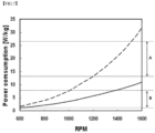
- FIG. 7 is a graph showing comparison in power consumption per unit mass between a CSTR and the reactor according to the present invention.
- a 4L CSTR operates at a rotational speed of 1200 to 1500 rpm to form a desired particle size when synthesizing a precursor and, when the rotational speed is converted into stirring power per unit mass, the corresponding value is about 13 to 27 W/kg (see region A of FIG. 7 ).
- a 0.5 L reactor used in a preparation method according to the present invention enables synthesis of a precursor with a desired particle size at a rotational speed of 600 rpm to 1400 rpm and, when the rotational speed is converted into stirring power per unit mass, the corresponding value is 1 W/kg to 8 W/kg (see region B of FIG. 7 ).
- the reactor used in a preparation method according to the present invention enables synthesis of a precursor with a desired particle size using less stirring power per unit mass than the CSTR. This indicates that the reactor has higher stirring efficiency than that of the CSTR.
- composite transition metal hydroxide particles prepared according to the method of the present invention have a small average diameter, exhibit monodisperse particle size distribution, and are uniform and thus exhibit excellent rate characteristics, excellent low-temperature rate characteristics, and excellent electrode density.
- the composite transition metal hydroxide particles have high crystallinity and thus have increased reactivity with a lithium precursor and, accordingly, a calcination temperature of a lithium composite transition metal oxide may be reduced.
Landscapes
- Chemical & Material Sciences (AREA)
- Inorganic Chemistry (AREA)
- Chemical Kinetics & Catalysis (AREA)
- Electrochemistry (AREA)
- General Chemical & Material Sciences (AREA)
- Organic Chemistry (AREA)
- Engineering & Computer Science (AREA)
- Manufacturing & Machinery (AREA)
- Materials Engineering (AREA)
- Battery Electrode And Active Subsutance (AREA)
- Inorganic Compounds Of Heavy Metals (AREA)
Applications Claiming Priority (3)
| Application Number | Priority Date | Filing Date | Title |
|---|---|---|---|
| KR20120011113 | 2012-02-03 | ||
| KR1020120097454A KR20130090312A (ko) | 2012-02-03 | 2012-09-04 | 리튬 이차전지용 리튬 복합 전이금속 산화물의 전구체 입자들 및 이를 포함하는 양극 활물질 |
| PCT/KR2013/000712 WO2013115544A1 (ko) | 2012-02-03 | 2013-01-29 | 리튬 이차전지용 리튬 복합 전이금속 산화물의 전구체 입자들 및 이를 포함하는 양극 활물질 |
Publications (3)
| Publication Number | Publication Date |
|---|---|
| EP2811555A1 EP2811555A1 (en) | 2014-12-10 |
| EP2811555A4 EP2811555A4 (en) | 2015-10-21 |
| EP2811555B1 true EP2811555B1 (en) | 2024-08-21 |
Family
ID=49215988
Family Applications (1)
| Application Number | Title | Priority Date | Filing Date |
|---|---|---|---|
| EP13743401.5A Active EP2811555B1 (en) | 2012-02-03 | 2013-01-29 | Method of preparation for precursor particles of lithium composite transition metal oxide using a rotating reactor |
Country Status (9)
| Country | Link |
|---|---|
| US (1) | US9590242B2 (pl) |
| EP (1) | EP2811555B1 (pl) |
| JP (1) | JP6284484B2 (pl) |
| KR (2) | KR20130090312A (pl) |
| CN (1) | CN103975464B (pl) |
| ES (1) | ES2989624T3 (pl) |
| HU (1) | HUE068507T2 (pl) |
| PL (1) | PL2811555T3 (pl) |
| WO (1) | WO2013115544A1 (pl) |
Families Citing this family (9)
| Publication number | Priority date | Publication date | Assignee | Title |
|---|---|---|---|---|
| CN103945934B (zh) * | 2012-02-01 | 2015-05-27 | 株式会社Lg化学 | 制备锂复合过渡金属氧化物的前体的反应器以及制备前体的方法 |
| KR101596272B1 (ko) * | 2013-01-03 | 2016-02-22 | 주식회사 엘지화학 | 리튬 복합 전이금속 산화물 제조용 장치, 이를 이용하여 제조된 리튬 복합 전이금속 산화물, 및 그 제조방법 |
| KR101608632B1 (ko) | 2013-08-20 | 2016-04-05 | 주식회사 엘지화학 | 리튬 복합 전이금속 산화물 제조용 전구체, 그 제조방법 및 이를 이용한 리튬 복합 전이금속 산화물 |
| WO2018047841A1 (ja) * | 2016-09-07 | 2018-03-15 | 協和化学工業株式会社 | 微粒子複合金属水酸化物、その焼成物、その製造方法及びその樹脂組成物 |
| KR20190075729A (ko) * | 2017-12-21 | 2019-07-01 | 재단법인 포항산업과학연구원 | 리튬 이차 전지용 양극 활물질 및 이의 제조 방법, 상기 양극 활물질을 포함하는 리튬 이차 전지 |
| CN112909238B (zh) | 2018-12-29 | 2022-04-22 | 宁德时代新能源科技股份有限公司 | 正极活性材料、正极极片及电化学储能装置 |
| JP6880086B2 (ja) | 2019-01-21 | 2021-06-02 | Jx金属株式会社 | 全固体リチウムイオン電池用酸化物系正極活物質、全固体リチウムイオン電池用酸化物系正極活物質の製造方法及び全固体リチウムイオン電池 |
| WO2020202602A1 (ja) | 2019-03-29 | 2020-10-08 | Jx金属株式会社 | 全固体リチウムイオン電池用酸化物系正極活物質、全固体リチウムイオン電池用酸化物系正極活物質の前駆体の製造方法、全固体リチウムイオン電池用酸化物系正極活物質の製造方法及び全固体リチウムイオン電池 |
| JP2024515012A (ja) * | 2021-03-10 | 2024-04-04 | ビーエーエスエフ ソシエタス・ヨーロピア | 粒子状(オキシ)水酸化物又は酸化物の製造方法 |
Family Cites Families (13)
| Publication number | Priority date | Publication date | Assignee | Title |
|---|---|---|---|---|
| US20040013941A1 (en) | 2002-05-20 | 2004-01-22 | Nichia Corporation | Positive electrode active material for a nonaqueous electrolyte secondary battery |
| US20060263690A1 (en) * | 2002-09-26 | 2006-11-23 | Seimi Chemical Co., Ltd. | Positive electrode active material for lithium secondary battery and process for producing the same |
| JP2004342548A (ja) * | 2003-05-19 | 2004-12-02 | Mitsubishi Chemicals Corp | リチウム二次電池用正極活物質及びその製造方法、並びに、それを用いたリチウム二次電池用正極材料、リチウム二次電池用正極及びリチウム二次電池 |
| CN101443273B (zh) * | 2006-02-17 | 2014-05-07 | 株式会社Lg化学 | 锂-金属复合氧化物的制备方法 |
| KR100765970B1 (ko) * | 2006-09-29 | 2007-10-10 | 대정화금주식회사 | 공침법을 이용한 망간 복합산화물 및 그 제조방법, 이를이용한 리튬이차전지용 스피넬형 양극활물질과 그 제조방법 |
| JP4211865B2 (ja) * | 2006-12-06 | 2009-01-21 | 戸田工業株式会社 | 非水電解質二次電池用Li−Ni複合酸化物粒子粉末及びその製造方法、並びに非水電解質二次電池 |
| JP5114998B2 (ja) * | 2007-03-29 | 2013-01-09 | 住友金属鉱山株式会社 | 非水系電解質二次電池用正極活物質、その製造方法及びそれを用いた非水系電解質二次電池 |
| WO2009145471A1 (ko) | 2008-04-03 | 2009-12-03 | 주식회사 엘지화학 | 리튬 복합 전이금속 산화물 제조용 신규 전구체 |
| JP5590283B2 (ja) * | 2008-09-22 | 2014-09-17 | 住友金属鉱山株式会社 | リチウム複合ニッケル酸化物およびその製造方法 |
| DE102010053411B4 (de) * | 2009-12-15 | 2023-07-06 | Vat Holding Ag | Vakuumventil |
| WO2012131779A1 (ja) * | 2011-03-31 | 2012-10-04 | 住友金属鉱山株式会社 | ニッケル複合水酸化物粒子および非水系電解質二次電池 |
| JP4894969B1 (ja) * | 2011-06-07 | 2012-03-14 | 住友金属鉱山株式会社 | ニッケルマンガン複合水酸化物粒子とその製造方法、非水系電解質二次電池用正極活物質とその製造方法、ならびに、非水系電解質二次電池 |
| CN103945934B (zh) * | 2012-02-01 | 2015-05-27 | 株式会社Lg化学 | 制备锂复合过渡金属氧化物的前体的反应器以及制备前体的方法 |
-
2012
- 2012-09-04 KR KR1020120097454A patent/KR20130090312A/ko active Pending
-
2013
- 2013-01-29 CN CN201380004172.XA patent/CN103975464B/zh active Active
- 2013-01-29 KR KR1020130010061A patent/KR101477497B1/ko active Active
- 2013-01-29 ES ES13743401T patent/ES2989624T3/es active Active
- 2013-01-29 HU HUE13743401A patent/HUE068507T2/hu unknown
- 2013-01-29 JP JP2014547125A patent/JP6284484B2/ja active Active
- 2013-01-29 EP EP13743401.5A patent/EP2811555B1/en active Active
- 2013-01-29 WO PCT/KR2013/000712 patent/WO2013115544A1/ko not_active Ceased
- 2013-01-29 PL PL13743401.5T patent/PL2811555T3/pl unknown
-
2014
- 2014-05-29 US US14/290,120 patent/US9590242B2/en active Active
Non-Patent Citations (1)
| Title |
|---|
| RICHTER O ET AL: "Effect of the rotor shape on the mixing characteristics of a continuous flow Taylor-vortex reactor", CHEMICAL ENGINEERING SCIENCE, OXFORD, GB, vol. 63, no. 13, 1 July 2008 (2008-07-01), pages 3504 - 3513, XP022710490, ISSN: 0009-2509, [retrieved on 20080406], DOI: 10.1016/J.CES.2008.04.003 * |
Also Published As
| Publication number | Publication date |
|---|---|
| KR101477497B1 (ko) | 2014-12-30 |
| US9590242B2 (en) | 2017-03-07 |
| KR20130090312A (ko) | 2013-08-13 |
| HUE068507T2 (hu) | 2024-12-28 |
| US20140272587A1 (en) | 2014-09-18 |
| JP6284484B2 (ja) | 2018-02-28 |
| PL2811555T3 (pl) | 2024-12-16 |
| EP2811555A4 (en) | 2015-10-21 |
| EP2811555A1 (en) | 2014-12-10 |
| WO2013115544A1 (ko) | 2013-08-08 |
| JP2015506075A (ja) | 2015-02-26 |
| CN103975464A (zh) | 2014-08-06 |
| CN103975464B (zh) | 2017-05-17 |
| ES2989624T3 (es) | 2024-11-27 |
| KR20130090341A (ko) | 2013-08-13 |
Similar Documents
| Publication | Publication Date | Title |
|---|---|---|
| EP2811555B1 (en) | Method of preparation for precursor particles of lithium composite transition metal oxide using a rotating reactor | |
| EP2289849B2 (en) | Precursor for production of lithium transition-metal oxide | |
| EP2802030B1 (en) | Precursor for preparing lithium composite transition metal oxide and method for preparing same | |
| KR102088508B1 (ko) | 다층 구조의 금속 산화물들을 포함하는 양극 활물질 제조용 전구체 및 이를 사용하여 제조된 리튬 이차전지용 양극 활물질 | |
| EP2261176B1 (en) | Novel precursor for the production of a lithium composite transition metal oxide | |
| EP2806486B1 (en) | Cathode active material, lithium secondary battery for controlling impurities or swelling containing same, and preparation method of cathode active material with improved productivity | |
| EP3576193B1 (en) | Positive electrode active material comprising a lithium-rich lithium manganese-based oxide with a lithium tungsten compound, and optionally an additional tungsten compound, formed on the surface thereof, and lithium secondary battery positive electrode comprising the same | |
| EP3291339B1 (en) | Method of preparing a precursor for preparation of lithium composite transition metal oxide | |
| US9029017B2 (en) | Lithium composite oxide for a lithium secondary battery and positive electrode for a lithium secondary battery including the lithium composite oxide | |
| EP2843737B1 (en) | Anode active material and lithium secondary battery comprising same | |
| US10903489B2 (en) | Precursor for preparation of lithium composite transition metal oxide, method for preparing the same and lithium composite transition metal oxide obtained from the same | |
| KR20160090580A (ko) | 양극 활물질, 그 제조방법 및 이를 포함하는 리튬이차전지 | |
| KR20160012558A (ko) | 리튬 이차 전지용 복합 양극 활물질 및 이를 함유하는 리튬 이차 전지용 양극을 포함한 리튬 이차 전지 | |
| EP2837600B1 (en) | Precursor for preparing lithium composite transition metal oxide | |
| EP2835848B1 (en) | Cathode material for secondary battery having improved lifetime characteristics and preparation method therefor |
Legal Events
| Date | Code | Title | Description |
|---|---|---|---|
| PUAI | Public reference made under article 153(3) epc to a published international application that has entered the european phase |
Free format text: ORIGINAL CODE: 0009012 |
|
| 17P | Request for examination filed |
Effective date: 20140526 |
|
| AK | Designated contracting states |
Kind code of ref document: A1 Designated state(s): AL AT BE BG CH CY CZ DE DK EE ES FI FR GB GR HR HU IE IS IT LI LT LU LV MC MK MT NL NO PL PT RO RS SE SI SK SM TR |
|
| AX | Request for extension of the european patent |
Extension state: BA ME |
|
| DAX | Request for extension of the european patent (deleted) | ||
| RA4 | Supplementary search report drawn up and despatched (corrected) |
Effective date: 20150918 |
|
| RIC1 | Information provided on ipc code assigned before grant |
Ipc: H01M 4/505 20100101ALI20150914BHEP Ipc: C01G 53/00 20060101ALI20150914BHEP Ipc: H01M 10/052 20100101ALI20150914BHEP Ipc: H01M 4/48 20100101AFI20150914BHEP Ipc: H01M 4/525 20100101ALI20150914BHEP |
|
| STAA | Information on the status of an ep patent application or granted ep patent |
Free format text: STATUS: EXAMINATION IS IN PROGRESS |
|
| 17Q | First examination report despatched |
Effective date: 20180713 |
|
| RAP1 | Party data changed (applicant data changed or rights of an application transferred) |
Owner name: LG CHEM, LTD. |
|
| RAP1 | Party data changed (applicant data changed or rights of an application transferred) |
Owner name: LG ENERGY SOLUTION LTD. |
|
| RAP3 | Party data changed (applicant data changed or rights of an application transferred) |
Owner name: LG ENERGY SOLUTION, LTD. |
|
| GRAP | Despatch of communication of intention to grant a patent |
Free format text: ORIGINAL CODE: EPIDOSNIGR1 |
|
| STAA | Information on the status of an ep patent application or granted ep patent |
Free format text: STATUS: GRANT OF PATENT IS INTENDED |
|
| INTG | Intention to grant announced |
Effective date: 20240531 |
|
| GRAS | Grant fee paid |
Free format text: ORIGINAL CODE: EPIDOSNIGR3 |
|
| GRAA | (expected) grant |
Free format text: ORIGINAL CODE: 0009210 |
|
| STAA | Information on the status of an ep patent application or granted ep patent |
Free format text: STATUS: THE PATENT HAS BEEN GRANTED |
|
| P01 | Opt-out of the competence of the unified patent court (upc) registered |
Free format text: CASE NUMBER: APP_38557/2024 Effective date: 20240627 |
|
| AK | Designated contracting states |
Kind code of ref document: B1 Designated state(s): AL AT BE BG CH CY CZ DE DK EE ES FI FR GB GR HR HU IE IS IT LI LT LU LV MC MK MT NL NO PL PT RO RS SE SI SK SM TR |
|
| REG | Reference to a national code |
Ref country code: GB Ref legal event code: FG4D |
|
| REG | Reference to a national code |
Ref country code: CH Ref legal event code: EP |
|
| REG | Reference to a national code |
Ref country code: IE Ref legal event code: FG4D |
|
| REG | Reference to a national code |
Ref country code: DE Ref legal event code: R096 Ref document number: 602013086010 Country of ref document: DE |
|
| REG | Reference to a national code |
Ref country code: NL Ref legal event code: FP |
|
| REG | Reference to a national code |
Ref country code: SE Ref legal event code: TRGR |
|
| REG | Reference to a national code |
Ref country code: ES Ref legal event code: FG2A Ref document number: 2989624 Country of ref document: ES Kind code of ref document: T3 Effective date: 20241127 |
|
| REG | Reference to a national code |
Ref country code: LT Ref legal event code: MG9D |
|
| REG | Reference to a national code |
Ref country code: HU Ref legal event code: AG4A Ref document number: E068507 Country of ref document: HU |
|
| PG25 | Lapsed in a contracting state [announced via postgrant information from national office to epo] |
Ref country code: NO Free format text: LAPSE BECAUSE OF FAILURE TO SUBMIT A TRANSLATION OF THE DESCRIPTION OR TO PAY THE FEE WITHIN THE PRESCRIBED TIME-LIMIT Effective date: 20241121 |
|
| REG | Reference to a national code |
Ref country code: AT Ref legal event code: MK05 Ref document number: 1716420 Country of ref document: AT Kind code of ref document: T Effective date: 20240821 |
|
| PG25 | Lapsed in a contracting state [announced via postgrant information from national office to epo] |
Ref country code: FI Free format text: LAPSE BECAUSE OF FAILURE TO SUBMIT A TRANSLATION OF THE DESCRIPTION OR TO PAY THE FEE WITHIN THE PRESCRIBED TIME-LIMIT Effective date: 20240821 Ref country code: PT Free format text: LAPSE BECAUSE OF FAILURE TO SUBMIT A TRANSLATION OF THE DESCRIPTION OR TO PAY THE FEE WITHIN THE PRESCRIBED TIME-LIMIT Effective date: 20241223 Ref country code: GR Free format text: LAPSE BECAUSE OF FAILURE TO SUBMIT A TRANSLATION OF THE DESCRIPTION OR TO PAY THE FEE WITHIN THE PRESCRIBED TIME-LIMIT Effective date: 20241122 |
|
| PG25 | Lapsed in a contracting state [announced via postgrant information from national office to epo] |
Ref country code: BG Free format text: LAPSE BECAUSE OF FAILURE TO SUBMIT A TRANSLATION OF THE DESCRIPTION OR TO PAY THE FEE WITHIN THE PRESCRIBED TIME-LIMIT Effective date: 20240821 |
|
| PG25 | Lapsed in a contracting state [announced via postgrant information from national office to epo] |
Ref country code: LV Free format text: LAPSE BECAUSE OF FAILURE TO SUBMIT A TRANSLATION OF THE DESCRIPTION OR TO PAY THE FEE WITHIN THE PRESCRIBED TIME-LIMIT Effective date: 20240821 |
|
| PG25 | Lapsed in a contracting state [announced via postgrant information from national office to epo] |
Ref country code: AT Free format text: LAPSE BECAUSE OF FAILURE TO SUBMIT A TRANSLATION OF THE DESCRIPTION OR TO PAY THE FEE WITHIN THE PRESCRIBED TIME-LIMIT Effective date: 20240821 Ref country code: IS Free format text: LAPSE BECAUSE OF FAILURE TO SUBMIT A TRANSLATION OF THE DESCRIPTION OR TO PAY THE FEE WITHIN THE PRESCRIBED TIME-LIMIT Effective date: 20241221 |
|
| PG25 | Lapsed in a contracting state [announced via postgrant information from national office to epo] |
Ref country code: HR Free format text: LAPSE BECAUSE OF FAILURE TO SUBMIT A TRANSLATION OF THE DESCRIPTION OR TO PAY THE FEE WITHIN THE PRESCRIBED TIME-LIMIT Effective date: 20240821 |
|
| PG25 | Lapsed in a contracting state [announced via postgrant information from national office to epo] |
Ref country code: RS Free format text: LAPSE BECAUSE OF FAILURE TO SUBMIT A TRANSLATION OF THE DESCRIPTION OR TO PAY THE FEE WITHIN THE PRESCRIBED TIME-LIMIT Effective date: 20241121 |
|
| PG25 | Lapsed in a contracting state [announced via postgrant information from national office to epo] |
Ref country code: RS Free format text: LAPSE BECAUSE OF FAILURE TO SUBMIT A TRANSLATION OF THE DESCRIPTION OR TO PAY THE FEE WITHIN THE PRESCRIBED TIME-LIMIT Effective date: 20241121 Ref country code: PT Free format text: LAPSE BECAUSE OF FAILURE TO SUBMIT A TRANSLATION OF THE DESCRIPTION OR TO PAY THE FEE WITHIN THE PRESCRIBED TIME-LIMIT Effective date: 20241223 Ref country code: NO Free format text: LAPSE BECAUSE OF FAILURE TO SUBMIT A TRANSLATION OF THE DESCRIPTION OR TO PAY THE FEE WITHIN THE PRESCRIBED TIME-LIMIT Effective date: 20241121 Ref country code: LV Free format text: LAPSE BECAUSE OF FAILURE TO SUBMIT A TRANSLATION OF THE DESCRIPTION OR TO PAY THE FEE WITHIN THE PRESCRIBED TIME-LIMIT Effective date: 20240821 Ref country code: IS Free format text: LAPSE BECAUSE OF FAILURE TO SUBMIT A TRANSLATION OF THE DESCRIPTION OR TO PAY THE FEE WITHIN THE PRESCRIBED TIME-LIMIT Effective date: 20241221 Ref country code: HR Free format text: LAPSE BECAUSE OF FAILURE TO SUBMIT A TRANSLATION OF THE DESCRIPTION OR TO PAY THE FEE WITHIN THE PRESCRIBED TIME-LIMIT Effective date: 20240821 Ref country code: GR Free format text: LAPSE BECAUSE OF FAILURE TO SUBMIT A TRANSLATION OF THE DESCRIPTION OR TO PAY THE FEE WITHIN THE PRESCRIBED TIME-LIMIT Effective date: 20241122 Ref country code: FI Free format text: LAPSE BECAUSE OF FAILURE TO SUBMIT A TRANSLATION OF THE DESCRIPTION OR TO PAY THE FEE WITHIN THE PRESCRIBED TIME-LIMIT Effective date: 20240821 Ref country code: BG Free format text: LAPSE BECAUSE OF FAILURE TO SUBMIT A TRANSLATION OF THE DESCRIPTION OR TO PAY THE FEE WITHIN THE PRESCRIBED TIME-LIMIT Effective date: 20240821 Ref country code: AT Free format text: LAPSE BECAUSE OF FAILURE TO SUBMIT A TRANSLATION OF THE DESCRIPTION OR TO PAY THE FEE WITHIN THE PRESCRIBED TIME-LIMIT Effective date: 20240821 |
|
| PGFP | Annual fee paid to national office [announced via postgrant information from national office to epo] |
Ref country code: HU Payment date: 20250117 Year of fee payment: 13 |
|
| PGFP | Annual fee paid to national office [announced via postgrant information from national office to epo] |
Ref country code: DE Payment date: 20241223 Year of fee payment: 13 |
|
| PG25 | Lapsed in a contracting state [announced via postgrant information from national office to epo] |
Ref country code: RO Free format text: LAPSE BECAUSE OF FAILURE TO SUBMIT A TRANSLATION OF THE DESCRIPTION OR TO PAY THE FEE WITHIN THE PRESCRIBED TIME-LIMIT Effective date: 20240821 Ref country code: SM Free format text: LAPSE BECAUSE OF FAILURE TO SUBMIT A TRANSLATION OF THE DESCRIPTION OR TO PAY THE FEE WITHIN THE PRESCRIBED TIME-LIMIT Effective date: 20240821 Ref country code: DK Free format text: LAPSE BECAUSE OF FAILURE TO SUBMIT A TRANSLATION OF THE DESCRIPTION OR TO PAY THE FEE WITHIN THE PRESCRIBED TIME-LIMIT Effective date: 20240821 |
|
| PGFP | Annual fee paid to national office [announced via postgrant information from national office to epo] |
Ref country code: ES Payment date: 20250207 Year of fee payment: 13 |
|
| PG25 | Lapsed in a contracting state [announced via postgrant information from national office to epo] |
Ref country code: EE Free format text: LAPSE BECAUSE OF FAILURE TO SUBMIT A TRANSLATION OF THE DESCRIPTION OR TO PAY THE FEE WITHIN THE PRESCRIBED TIME-LIMIT Effective date: 20240821 |
|
| PG25 | Lapsed in a contracting state [announced via postgrant information from national office to epo] |
Ref country code: CZ Free format text: LAPSE BECAUSE OF FAILURE TO SUBMIT A TRANSLATION OF THE DESCRIPTION OR TO PAY THE FEE WITHIN THE PRESCRIBED TIME-LIMIT Effective date: 20240821 |
|
| PG25 | Lapsed in a contracting state [announced via postgrant information from national office to epo] |
Ref country code: SK Free format text: LAPSE BECAUSE OF FAILURE TO SUBMIT A TRANSLATION OF THE DESCRIPTION OR TO PAY THE FEE WITHIN THE PRESCRIBED TIME-LIMIT Effective date: 20240821 |
|
| PGFP | Annual fee paid to national office [announced via postgrant information from national office to epo] |
Ref country code: IT Payment date: 20241224 Year of fee payment: 13 |
|
| PGFP | Annual fee paid to national office [announced via postgrant information from national office to epo] |
Ref country code: TR Payment date: 20250108 Year of fee payment: 13 |
|
| REG | Reference to a national code |
Ref country code: DE Ref legal event code: R097 Ref document number: 602013086010 Country of ref document: DE |
|
| PLBE | No opposition filed within time limit |
Free format text: ORIGINAL CODE: 0009261 |
|
| STAA | Information on the status of an ep patent application or granted ep patent |
Free format text: STATUS: NO OPPOSITION FILED WITHIN TIME LIMIT |
|
| 26N | No opposition filed |
Effective date: 20250522 |
|
| REG | Reference to a national code |
Ref country code: CH Ref legal event code: PL |
|
| PG25 | Lapsed in a contracting state [announced via postgrant information from national office to epo] |
Ref country code: MC Free format text: LAPSE BECAUSE OF FAILURE TO SUBMIT A TRANSLATION OF THE DESCRIPTION OR TO PAY THE FEE WITHIN THE PRESCRIBED TIME-LIMIT Effective date: 20240821 Ref country code: LU Free format text: LAPSE BECAUSE OF NON-PAYMENT OF DUE FEES Effective date: 20250129 |
|
| PG25 | Lapsed in a contracting state [announced via postgrant information from national office to epo] |
Ref country code: CH Free format text: LAPSE BECAUSE OF NON-PAYMENT OF DUE FEES Effective date: 20250131 |
|
| PGFP | Annual fee paid to national office [announced via postgrant information from national office to epo] |
Ref country code: GB Payment date: 20251222 Year of fee payment: 14 |
|
| PGFP | Annual fee paid to national office [announced via postgrant information from national office to epo] |
Ref country code: FR Payment date: 20251223 Year of fee payment: 14 Ref country code: NL Payment date: 20251223 Year of fee payment: 14 |
|
| PGFP | Annual fee paid to national office [announced via postgrant information from national office to epo] |
Ref country code: BE Payment date: 20251229 Year of fee payment: 14 |
|
| PGFP | Annual fee paid to national office [announced via postgrant information from national office to epo] |
Ref country code: SE Payment date: 20251223 Year of fee payment: 14 |
|
| PG25 | Lapsed in a contracting state [announced via postgrant information from national office to epo] |
Ref country code: IE Free format text: LAPSE BECAUSE OF NON-PAYMENT OF DUE FEES Effective date: 20250129 |
|
| PGFP | Annual fee paid to national office [announced via postgrant information from national office to epo] |
Ref country code: PL Payment date: 20251229 Year of fee payment: 14 |