EP2811496B1 - Elektromagnetische Verbinder - Google Patents
Elektromagnetische Verbinder Download PDFInfo
- Publication number
- EP2811496B1 EP2811496B1 EP14166908.5A EP14166908A EP2811496B1 EP 2811496 B1 EP2811496 B1 EP 2811496B1 EP 14166908 A EP14166908 A EP 14166908A EP 2811496 B1 EP2811496 B1 EP 2811496B1
- Authority
- EP
- European Patent Office
- Prior art keywords
- magnetic
- core
- module
- backplane
- cores
- Prior art date
- Legal status (The legal status is an assumption and is not a legal conclusion. Google has not performed a legal analysis and makes no representation as to the accuracy of the status listed.)
- Active
Links
Images


Classifications
-
- H—ELECTRICITY
- H01—ELECTRIC ELEMENTS
- H01F—MAGNETS; INDUCTANCES; TRANSFORMERS; SELECTION OF MATERIALS FOR THEIR MAGNETIC PROPERTIES
- H01F38/00—Adaptations of transformers or inductances for specific applications or functions
- H01F38/14—Inductive couplings
-
- H—ELECTRICITY
- H01—ELECTRIC ELEMENTS
- H01F—MAGNETS; INDUCTANCES; TRANSFORMERS; SELECTION OF MATERIALS FOR THEIR MAGNETIC PROPERTIES
- H01F41/00—Apparatus or processes specially adapted for manufacturing or assembling magnets, inductances or transformers; Apparatus or processes specially adapted for manufacturing materials characterised by their magnetic properties
- H01F41/02—Apparatus or processes specially adapted for manufacturing or assembling magnets, inductances or transformers; Apparatus or processes specially adapted for manufacturing materials characterised by their magnetic properties for manufacturing cores, coils, or magnets
-
- Y—GENERAL TAGGING OF NEW TECHNOLOGICAL DEVELOPMENTS; GENERAL TAGGING OF CROSS-SECTIONAL TECHNOLOGIES SPANNING OVER SEVERAL SECTIONS OF THE IPC; TECHNICAL SUBJECTS COVERED BY FORMER USPC CROSS-REFERENCE ART COLLECTIONS [XRACs] AND DIGESTS
- Y10—TECHNICAL SUBJECTS COVERED BY FORMER USPC
- Y10T—TECHNICAL SUBJECTS COVERED BY FORMER US CLASSIFICATION
- Y10T29/00—Metal working
- Y10T29/49—Method of mechanical manufacture
- Y10T29/49002—Electrical device making
- Y10T29/4902—Electromagnet, transformer or inductor
- Y10T29/49071—Electromagnet, transformer or inductor by winding or coiling
Definitions
- the present invention relates to the field of electrical connector systems.
- the preferred embodiments of the present invention are used as connectors between backplanes and modules mounted on the backplanes, and accordingly the prior art relating to such connectors will be discussed. However it is to be understood that use of the present invention is not so limited, and the invention may be adapted for as wide range of use.
- the connector housings are round and include an alignment feature plus a rotary collar on one connector member that screws onto the other connector member to maintain positive engagement of the connector members, with an O-ring providing the ultimate seal of the pins and sockets in the connector.
- a backplane is a printed circuit board into which boards or modules are "plugged”, which backplane printed circuit board provides power to and/or communication with the module or printed circuit mounted on the backplane printed circuit board, or the entire assembly that includes such a backplane printed circuit board.
- a simple edge connector is adequate for applications wherein one can be assured that the environment will not be hostile.
- circuit failure detection techniques and/or error detection and correction techniques are commonly used, as is redundancy in circuitry to provide high reliability in circuit operation over long periods of time.
- corrosion is a persistent problem and may render an initially good contact nonfunctional, as such assemblies may sit almost indefinitely without attention until a failure does occur. Therefore conventional connectors remain a weak link in the overall system.
- EP 1 885 085 A1 which describes an apparatus which may be a backplane for mechanically coupling modules of a bus system to that bus.
- a power interface for contact-free power supply of the modules, and a data interface for contact-free coupling to the databus is provided.
- US2003094855 A1 describes an array for the contact-less transmission of electrical signals or energy from at least one transmitter to several receivers.
- US5229652 A discloses a non-contact way to provide electrical power and two-way digital communications between a host computer and its peripheral modules, such as IC memory cards, modems, and A/D converters.
- the invention is directed to connector systems as set forth in claims 1, 2, and 23 and to a method of coupling power from a backplane to a module to be coupled to the backplane and for signal transmission as set forth in claim 18.
- a section of a backplane circuit board 26 in accordance with one embodiment of the present invention may be seen.
- a typical backplane circuit board 26 in accordance with this embodiment will have a plurality of openings or holes 20 there through, each for the receipt of an I-core during assembly of the backplane, together with one or more groups of openings 22 and 24, each for receipt of an E-core.
- An I-core of the type preferably used will be in the form of a round cylindrical slug of magnetic material, in a preferred embodiment a ferrite suitable for use at high frequencies.
- the E-cores of a typical embodiment will be conventional E-cores, in the embodiment being described, also ferrite E-cores which may be the same grade of ferrite or a different grade of ferrite than the I-cores.
- the E-core devices are used for the transfer of power to a module "plugged" into the backplane using a connector in accordance with an embodiment of the present invention, whereas the I-core devices are used for communication purposes.
- the E-core ferrite (or other material) will be selected for its relatively high saturation density for best power transfer, whereas the I-core ferrite (or other material) will be selected for its high frequency capabilities to assure maximum signal communication bandwidth. Consequently, one aspect of this invention is the separation of the power and signal transfer rather than trying to transfer power and signals in a single magnetic device, and also the optional use of different magnetic materials, preferably the use of different grades of ferrite, for the power and signal transfer devices to allow maximizing the performance of each.
- the backplane circuit board 26 of Fig. 1 will typically be a multilayer board with planar (printed) windings 25 and 27 on each of the multiple layers connected in series with the same winding sense to achieve multiple turn windings, each associated with an I-core opening 20 or the center opening 22 of an E-core opening group 22, 24.
- planar windings are well known and may be formed, by way of example, by forming printed helical or modified helical conductive traces 25 of opposite winding sense on alternate layers of the multilayered printed circuit board 26 and then by connecting the inner ends of the conductive traces of the first and second layers, the outer ends of the conductive traces on the second and third layers, etc.
- Such interconnection may be by way of example by the use of plated through holes at different locations (angles) around the inner and outer peripheries of the windings.
- the interconnector may be made as between alternate board layers as the multilayer circuit board is fabricated. By using such a winding, the total number of turns that may be achieved, while less than a typical wire wound coil, can still be substantial.
- the planar windings could be around either or both regions 24, or around both regions 24 and 22 as long as they were properly interconnected to achieve the required complementary winding sense.
- a section of the circuit board 26 with E-cores 28 and I-cores 30 placed therein a label 32 with an adhesive on the top surface thereof is placed under the circuit board 26 and the E-cores 28 and I-cores 30 are placed in position in the board 32 by a typical pick-and-place machine, with the E-cores and I-cores strongly adhering to the adhesive side of the label 32.
- the openings in the printed circuit board 26 are slightly larger than the E-cores 28 and I-cores 30 so as to leave some gap around the cores for subsequent filling by an appropriate potting compound.
- the potting compound may be a hard potting compound such as an epoxy or alternatively may be a flexible potting compound such as a silicon rubber.
- a silicon rubber will provide some flexibility between the E-cores 28 and I-cores 30 and the backplane printed circuit board 26, if needed. However such flexibility may not be needed in that the combination of the printed circuit board and a rigid potting material makes the printed circuit board very rigid to avoid backplane flexing. Also the backplane printed circuit board will not be subject to the relatively high forces of prior art backplane printed circuit boards because of the absence of any high forces thereon required for full prior art connector engagement, though vibration may be encountered in some applications. In the claims to follow, materials such a epoxy and silicon rubber are considered positive mounts for the respective cores because they hold the cores in place, as opposed to being spring mounted to accommodate meaningful deflection under force.
- the assembled backplane printed circuit board 26 will in turn become part of a larger assembly forming some part of a support chassis which may vary considerably, depending on the application.
- the E-cores 28 on the backplane printed circuit board 26 meet with a respective E-core in a module to be connected to the backplane. Since in preferred embodiments such E-cores are used for the transfer of AC power from the backplane to a module mounted on the backplane, highly efficient energy transfer from the primary planar windings 25 on the backplane multilayer printed circuit board 26 to the wire windings on the E-cores in the module requires a minimum gap in the magnetic circuit formed by that E-core pair.
- the label 32 is a 0.005 inch Lexan label on the backplane printed circuit board 26 and a corresponding Lexan member protecting the E-cores in the module. Note that a 0.005 inch protection of each leg of each E-core itself causes a 0.020 gap in the magnetic circuit formed by an E-core pair.
- the E-cores in both the backplane printed circuit board 26 and in the module were positively fixed in position, that would require providing extra spacing to allow for a variation in that fixed position, both initially and due to thermal expansion and warpage effects that might be caused by heat generated in the module.
- the E-cores in the module connector are spring loaded so as to slightly protrude from the mounting plane of the module to lie flat against the respective E-cores on the backplane printed circuit board 26 (of course with their protective layers there between) with the spring depressing as required when the module is located in its final position. This spring loading assures a constant minimum gap defined by the protective layers over the E-cores in spite of the differential expansion, warpage in the assembly, vibration, etc., yet very much limits the pressure on the E-cores regardless of such factors.
- Fig. 3A is an exploded view of the E-core assembly used in one embodiment for the module side of the connector.
- the exploded view is shown with the face of the E-core directed downward, though in the actual assembly the face of the E-core 28 would be directed outward beyond the edge of a printed circuit board in the module, with cover 34 covering most of the E-core.
- the center leg 36 of the E-core passes through winding bobbin 38 on member 40 which in turn has a number of electrical contacts or terminals 42 around the edge thereof. These terminals, when soldered to a printed circuit board in the module, become the support for the assembly and also act as the terminals to which the leads on the wire wound coil on bobbin 38 are connected.
- a single coil with multiple taps on the coil is typically used to provide various AC voltage outputs which then are converted to associated DC voltages as typically required for operation of a module.
- the planar and wire wound windings might be instead placed around the outer legs, though this is not preferred, as it does not package as well as the single winding around the center legs.
- member 40 is assembled thereto and the center leg 36 of E-core 28 is inserted through the center of bobbin 38. Also a spring 46 is compressed against member 44 and temporarily held in the compressed state by a thin blade inserted through slot 48 in cover 34 so that the cover 34 with compressed spring 46 may be placed over the assembly comprising E-core 28, bobbin 38 and member 40. Then the spring 46 is released so that the spring will encourage E-core 28 away from member 44, yet will allow E-core 28 some movement, relative to the bobbin, against the force of the spring 46 when it contacts the associated E-core on the backplane through the protective layers over the face of each E-core.
- a very thin protective coating may be put over the E-core if desired, at least all except the outward extending face of the E-core, such as, by way of example, by dipping the E-core in a very thin epoxy or other binder.
- the assembly of cover 34 with compressed spring 46 to the rest of the assembly shown in Fig. 3A may be done before terminals 42 are soldered to the printed circuit board in the module, or alternatively, after the assembly of E-core 28 and bobbin 38 in member 40 with terminals 42 thereon.
- pins 50 on member 40 extend into holes in the printed circuit board in the module to provide accurate alignment of the assembly with the circuit board 26 without relying on the soldered terminals 42 for positioning the assembly.
- the winding bobbin 54 on a support 52 for the I-cores 30 may be seen.
- two I-cores end to end do not make a complete magnetic circuit, but instead depend on completion of the magnetic circuit (a return path) through air or non-magnetic materials surrounding the I-cores. Consequently because part of the magnetic circuit is made up of non magnetic materials anyway, communication through the I-cores is not nearly as sensitive to the gap between the respective pair of I-cores as is power transfer through the gap between the power transferring E-cores during operation of the connector.
- a plastic member 52 is molded with an integral winding bobbin 54 and locating pin 56 with conductors 58 being either molded in or attached thereto.
- the pin 56 like pins 50 of Fig. 3A , provide a locating reference relative to a corresponding hole in the printed circuit board with terminals or supporting feet 58 providing mounting support much like terminals 42 of Fig. 3A .
- multiple terminals 58 are shown, most are simply used for support, as unlike the secondary on the E-cores which typically has multiple taps, a single coil without taps is used for the secondary winding on the I-cores 30.
- the I-core 30 is cemented into member 52 with the end 60 being flush with the face of the bobbin 54.
- Fig. 5 is a perspective view of a module connector E-core and I-core assemblies on an edge of a circuit board in the module
- Fig. 6 is a view of the connector edge of the module without the protective layer over the assembly so as to illustrate the arrangement of the E-core and I-core assemblies, which assemblies are not visible with the protective layer in place.
- protective layer in one embodiment is another 0.005 inch thick Lexan sheet fastened in position around its edges to a floating support, which leaves sufficient flexibility for the application.
- the mounting screw holes surrounded by projections 62 which fit into corresponding holes in the backplane assembly for accurately locating the module on the backplane assembly. Projection 62 and the holes in the backplane assembly may be the same, or may be purposely made of different shapes or diameters, etc. to prevent mounting the module backward or upside down.
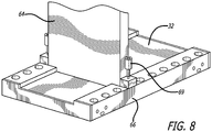
- Figs. 7 and 8 The final assembly of an exemplary embodiment is illustrated in Figs. 7 and 8 .
- Fig. 7 is an exploded view of the backplane assembly comprising the backplane circuit board 26 with the E-cores 28 and I-cores 30 thereon, the backplane rails 66 and cover 68 protecting the back of the backplane circuit board 26.
- Fig. 8 shows a module 64 mounted in slot 4 of the backplane assembly by screws 69.
- the label 32 covers the backplane circuit board 26 and identifies the slots by number.
- E-cores and I-cores were used for the coupling of power and signals, respectively.
- the use of I-cores is highly desirable for signals, as they perform well at the high frequencies used for signal transmission (preferably using Manchester or other coding having a zero DC value), and package compactly in a final connector assembly, though other shaped cores could be used if desired.
- C-cores such as shown in schematic form in Fig. 3B .
- planar windings on the backplane and the wire wound windings 38 on the module connector are on both legs of the C-cores 29, though these windings 38 could be on one leg only. If such windings were on one leg only, they should be on the same leg, not on opposite legs, to minimize flux leakage. Otherwise the assemblies are as described herein.
- shielding is best provided by conductive enclosures rather than magnetic enclosures, particularly for the I-cores.
- Such conductive enclosures may be provided, for example, by aluminum stampings or metal plated plastic enclosures.
- any such shielding should be spaced somewhat away from the I-cores so as to not choke off that space, but instead only contain the much lower flux density that would otherwise extend outward in significant strength over greater distances.
- the planar windings for the I-cores on the backplane circuit board include a grounded ring encircling the face of each respective I-core, but spaced outward to allow space for the flux as described.
- electromagnetic connectors using two E-cores assemblies and three I-core assemblies are shown.
- the E-core assemblies are essentially identical, one serving as the primary source of power for the module and the other serving as a backup source of power for the module.
- the three I-core assemblies one provides communication from the backplane to the module, one provides communication from the module to the backplane, and one provides a lower frequency bidirectional communication for such purposes as monitoring and supervisory functions.
- the use of two electromagnetic power transfer assemblies and three electromagnetic communication assemblies is application dependent, and fewer or more such assemblies may be used as required.
- the slot is periodically pinged when a module is not present by very temporarily powering the slot (an E-core primary planar winding or both E-core primary windings) and sensing the apparent inductance or impedance of the primary planar winding. If no module is present, the inductance will be very low, and the impedance will also be very low, not much more than the resistance of the respective E-core planar winding.
- the presence of a module may be sensed, even in the presence of a shorted wire wound secondary on one of the E-cores in the module (or backplane), or an open primary on one of the E-core planar windings by sensing no current when pinged, allowing disabling of the affected C-core pair, flagging the failure and continuing operation of the module using the other pair of E-cores for powering the module.
- Removal (or certain failures) of a module may be similarly detected by detecting a planar primary of one or both E-cores that is above the maximum allowed for a properly functioning module properly mounted to the backplane.
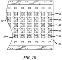
- Fig. 9 is an illustration of the rear of a module using C-cores 29 for the power connection of the connector
- Fig. 10 is an illustration of a backplane using corresponding C-cores 29, in both cases the C-cores replacing the E-cores 28.
- E-core is used herein and in the claims in a general sense to mean a magnetic core that has a cross section in the form of an E. This definition covers not only the E-core configuration shown herein, but also cores having a configuration of a surface of revolution or partial surface of revolution generated by rotating an E-core about the axis of its center leg.
- E-core would have to have an outer edge interrupted to allow the planar windings on the backplane to extend into the space between the center and the rim of the surface of revolution and to allow the exit of the wires on the windings in the module, but otherwise would function properly.
- the symmetry of the I-cores and the E-cores or C-cores allows the module to be assembled into a slot on the backplane with either orientation.
- the module is comprised to two identical circuits to provide a backup circuit if the one being used fails, or for both to operate so that a failure can be detected by the two having different results. Either way, the center I-core assembly can be used to talk to the module, and the other 2 I-core assemblies used for the module to talk to the backplane. Because of the symmetry, it doesn't matter which circuit is to talk to the backplane through which of the two I-core assemblies.
- circuitry in the module is not symmetrical, when the presence of a module is detected on insertion of a module, the module needs to be pinged for the module to identify itself.
- Incorporated in that circuitry and process can be a detection of a response tailored to identify the module orientation, after which the circuitry in the module or coupled to the backplane may reroute power and/or signals as appropriate.
Landscapes
- Engineering & Computer Science (AREA)
- Power Engineering (AREA)
- Manufacturing & Machinery (AREA)
- Coils Or Transformers For Communication (AREA)
- Details Of Connecting Devices For Male And Female Coupling (AREA)
Claims (24)
- Verbindersystem zum Übertragen von Leistung von einer Rückwand zu einem auf der Rückwand montierten Modul (64), umfassend:einen ersten magnetischen E-Kern (28) mit einem Mittelschenkel (36) und einem ersten und einem zweiten Außenschenkel, wobei der Mittelschenkel und die Außenschenkel an einem ersten Ende derselben verbunden sind und derart montiert sind, dass sich ein zweites Ende derselben in Öffnungen (22, 24) in der Rückwand erstreckt, wobei die Rückwand eine gedruckte Spule (27) aufweist, die mindestens einen der drei Schenkel umgibt;einen zweiten magnetischen E-Kern (28) mit einem Mittelschenkel (36) und einem ersten und einem zweiten Außenschenkel, wobei der Mittelschenkel und die Außenschenkel an einem ersten Ende derselben verbunden sind und derart montiert sind, dass ein zweites Ende derselben einem Ende des Moduls benachbart montiert ist, wobei das Modul (64) mindestens eine Wickelspule aufweist, die mindestens einen der drei Schenkel umgibt;wobei die Rückwand und das Modul derart konfiguriert sind, dass das zweite Ende jedes Schenkels des magnetischen E-Kerns auf der Rückwand auf den entsprechenden Schenkel des magnetischen E-Kerns in dem Modul ausgerichtet ist, wenn das Modul an der Rückwand montiert ist; undaußerdem zur Signalübertragung für eine Rückwand zu einem auf der Rückwand montierten Modul und/oder einem Modul zu einer Rückwand, an der das Modul montiert ist, ferner umfassend:einen ersten und einen zweiten magnetischen I-Kern (30);wobei der erste magnetische I-Kern derart montiert ist, dass sich ein Ende desselben in eine Öffnung (20) in der Rückwand erstreckt, wobei die Rückwand eine den ersten magnetischen I-Kern umgebende gedruckte Spule (25) aufweist;wobei ein Ende des zweiten magnetischen I-Kerns einem Ende des Moduls benachbart montiert ist, wobei das Modul (64) mindestens eine den zweiten magnetischen I-Kern umgebende Wickelspule aufweist;wobei die Rückwand und das Modul außerdem derart konfiguriert sind, dass das Ende des ersten magnetischen I-Kerns dem Ende des zweiten magnetischen I-Kerns benachbart ist, wenn das Modul an der Rückwand montiert ist.
- Verbindersystem zum Übertragen von Leistung von einer Rückwand zu einem auf der Rückwand montierten Modul, umfassend:einen ersten magnetischen C-Kern (29) mit einem ersten und einem zweiten Schenkel, wobei der erste und der zweite Schenkel an einem ersten Ende derselben verbunden sind und derart montiert sind, dass sich ein zweites Ende derselben in Öffnungen (24) in der Rückwand erstreckt, wobei die Rückwand eine gedruckte Spule (27) aufweist, die mindestens einen von dem ersten und dem zweiten Schenkel umgibt;einen zweiten magnetischen C-Kern (29) mit einem ersten und einem zweiten Schenkel, wobei der erste und der zweite Schenkel an einem ersten Ende derselben verbunden sind und derart montiert sind, dass ein zweites Ende derselben einem Ende des Moduls benachbart montiert ist, wobei das Modul (64) mindestens eine Drahtwickelspule aufweist, die mindestens einen von dem ersten und dem zweiten Schenkel umgibt;wobei die Rückwand und das Modul derart konfiguriert sind, dass das zweite Ende jedes Schenkels des magnetischen C-Kerns auf der Rückwand auf den entsprechenden Schenkel des magnetischen C-Kerns in dem Modul ausgerichtet ist, wenn das Modul (64) an der Rückwand montiert ist; undaußerdem zur Signalübertragung für eine Rückwand zu einem auf der Rückwand montierten Modul und/oder einem Modul zu einer Rückwand, an der das Modul montiert ist, ferner umfassend:einen ersten und einen zweiten magnetischen I-Kern (30);wobei der erste magnetische I-Kern derart montiert ist, dass sich ein Ende desselben in eine Öffnung (20) in der Rückwand erstreckt, wobei die Rückwand eine den ersten magnetischen I-Kern umgebende gedruckte Spule (25) aufweist;wobei ein Ende des zweiten magnetischen I-Kerns (30) einem Ende des Moduls benachbart montiert ist, wobei das Modul mindestens eine den zweiten magnetischen I-Kern umgebende Wickelspule aufweist;wobei die Rückwand und das Modul außerdem derart konfiguriert sind, dass das Ende des ersten magnetischen I-Kerns dem Ende des zweiten magnetischen I-Kerns benachbart ist, wenn das Modul an der Rückwand montiert ist.
- Verbindersystem nach Anspruch 1 oder Anspruch 2, wobei es sich bei der Wickelspule in dem Modul (64) um eine Spule mit mehreren Abgriffen handelt.
- Verbindersystem nach einem der Ansprüche 1 bis 3, wobei die zweiten Enden des magnetischen E-Kerns oder magnetischen C-Kerns in der Rückwand nicht von der Modulseite der Rückwand vorstehen.
- Verbindersystem nach Anspruch 4, wobei die zweiten Enden des ersten und des zweiten magnetischen E-Kerns oder magnetischen C-Kerns jeweils eine Schutzfolie oder -schicht darüber aufweisen.
- Verbindersystem nach Anspruch 4, wobei der magnetische E-Kern oder magnetische C-Kern in dem Modul federnd (46) gelagert ist, um eine Federkraft zwischen dem magnetischen E-Kern oder magnetischen C-Kern in dem Modul und dem magnetischen E-Kern oder magnetischen C-Kern in der Rückwand bereitzustellen, wenn das Modul an der Rückwand montiert ist.
- Verbindersystem nach Anspruch 1, wobei das Verbindersystem ferner Folgendes umfasst:mindestens einen dritten und einen vierten magnetischen E-Kern oder magnetischen C-Kern, wobei der dritte magnetische E-Kern oder magnetische C-Kern wie der erste magnetische E-Kern oder magnetische C-Kern auf der Rückwand konfiguriert ist und der vierte magnetische E-Kern oder magnetische C-Kern dem Ende des Moduls benachbart montiert ist und wie der zweite magnetische E-Kern oder magnetische C-Kern konfiguriert ist;mindestens einen dritten und einen vierten magnetischen I-Kern, wobei der dritte magnetische I-Kern wie der erste magnetische I-Kern auf der Rückwand konfiguriert ist und der vierte magnetische I-Kern dem Ende des Moduls benachbart montiert ist und wie der zweite magnetische I-Kern konfiguriert ist;wobei der erste und der zweite magnetische E-Kern oder magnetische C-Kern um eine Mitte des Moduls symmetrisch zu dem dritten und dem vierten magnetischen E-Kern oder magnetischen C-Kern montiert sind;wobei der erste und der zweite magnetische I-Kern um eine Mitte des Moduls symmetrisch zu dem dritten und dem vierten magnetischen I-Kern montiert sind;wodurch das Verbindersystem funktionsfähig sein wird, wenn das Modul in einer ersten relativen Orientierung oder einer gegenüber der ersten relativen Orientierung umgekehrten zweiten relativen Orientierung an der Rückwand montiert sein kann.
- Verbindersystem nach Anspruch 7, wobei das Modul zwei identische Stromkreise enthält.
- Verbindersystem nach Anspruch 7, wobei das mit der Rückwand verbundene Modul Schaltungen zum Abfühlen der relativen Orientierung des Moduls und zum Umleiten von Leistung und/oder Signalen nach Bedarf umfasst.
- Verbindersystem nach einem der Ansprüche 1 bis 9, wobei das Ende des ersten magnetischen I-Kerns in der Rückwand nicht von der Modulseite der Rückwand vorsteht.
- Verbindersystem nach einem der Ansprüche 1 bis 10, wobei die Enden jedes der magnetischen I-Kerne eine Schutzfolie oder -schicht darüber aufweisen.
- Verbindersystem nach einem der Ansprüche 1 bis 11, wobei die magnetischen I-Kerne in dem Modul und in der Rückwand in dem Modul bzw. in der Rückwand formschlüssig montiert sind.
- Verbindersystem nach Anspruch 12, wobei der magnetische I-Kern in der Rückwand derart in der Rückwand montiert ist, dass eine Achse des magnetischen I-Kerns zu der Rückwand senkrecht ist, und wobei der magnetische I-Kern in dem Modul derart montiert ist, dass eine Achse mit der Achse des magnetischen I-Kerns in der Rückwand im Wesentlichen kollinear ist, wenn das Modul an der Rückwand montiert ist.
- Verbindersystem nach Anspruch 13, wobei die magnetischen I-Kerne derart montiert sind, dass, wenn das Modul an der Rückwand montiert ist, sich die Enden der magnetischen I-Kerne in unmittelbarer Nähe befinden, ohne eine mechanische Kraft entlang ihrer Achsen aufeinander auszuüben.
- Verbindersystem nach einem der Ansprüche 1 bis 14, wobei es sich bei den magnetischen I-Kernen um Ferrit-I-Kerne handelt.
- Verbindersystem nach einem der Ansprüche 1 bis 15, wobei es sich bei den magnetischen E-Kernen oder magnetischen C-Kernen und den magnetischen I-Kernen um Ferritkerne handelt, wobei die magnetischen E-Kerne oder magnetischen C-Kerne aus Ferrit einer Güte sind und die magnetischen I-Kerne aus Ferrit einer von der ersten Güte verschiedenen zweiten Güte sind.
- Verbindersystem nach einem der Ansprüche 1 bis 16, wobei es sich bei den magnetischen E-Kernen oder magnetischen C-Kernen um Ferrit-E-Kerne bzw. Ferrit-C-Kerne handelt.
- Verfahren zum Koppeln von Leistung von einer Rückwand zu einem an die Rückwand zu koppelnden Modul, umfassend:Montieren eines ersten magnetischen C-Kerns (29) oder E-Kerns (28) auf einer Rückwandplatine (26), sodass sich Stirnflächen derselben in Öffnungen (22, 24) in der Rückwand erstrecken, wobei die Rückwandplatine mindestens eine Planarspule (27) in der Rückwandplatine aufweist, die mindestens einen Schenkel des ersten magnetischen C-Kerns oder E-Kerns umgibt;Bereitstellen eines zweiten magnetischen C-Kerns (29) oder E-Kerns (28), der derart in einem Modul montiert ist, dass Stirnflächen desselben einer Moduloberfläche benachbart sind, wobei der zweite magnetische C-Kern oder E-Kern eine Drahtwickelspule aufweist, die mindestens einen Schenkel des zweiten magnetischen C-Kerns oder E-Kerns umgibt;wodurch, wenn das Modul (64) an die Rückwand gekoppelt ist, die Stirnflächen des zweiten magnetischen C-Kerns oder E-Kerns an dem Modul den Stirnflächen des ersten magnetischen C-Kerns oder E-Kerns auf der Rückwandplatine benachbart sein werden, elektrische Wechselstromleistung an die Planarspule (27) angelegt und an die Drahtwickelspule gekoppelt werden kann; undaußerdem zur Signalübertragung für eine Rückwand zu einem auf der Rückwand montierten Modul und/oder einem Modul zu einer Rückwand, an der das Modul montiert ist, ferner umfassend:Bereitstellen eines ersten und eines zweiten magnetischen I-Kerns (30);Montieren des ersten magnetischen I-Kerns derart, dass ein Ende desselben (20) durch eine Öffnung in der Rückwand gelangt, wobei die Rückwand eine den ersten magnetischen I-Kern umgebende gedruckte Spule (25) aufweist;Montieren des zweiten magnetischen I-Kerns derart, dass ein Ende desselben einem Ende des Moduls benachbart ist, wobei der zweite magnetische I-Kern mindestens eine den zweiten magnetischen I-Kern umgebende Wickelspule aufweist, und sodass das Ende des ersten magnetischen I-Kerns dem Ende des zweiten magnetischen I-Kerns benachbart ist, wenn das Modul an der Rückwand montiert ist.
- Verfahren nach Anspruch 18, wobei die Drahtwickelspule an dem zweiten magnetischen C-Kern oder E-Kern und/oder die zweiten Enden des magnetischen C-Kerns oder E-Kerns wie in einem der Ansprüche 3 bis 5 definiert sind.
- Verfahren nach Anspruch 18, ferner umfassend das federnde (46) Lagern des zweiten magnetischen C-Kerns oder E-Kerns in dem Modul, um eine Federkraft zwischen dem ersten magnetischen C-Kern oder E-Kern in der Rückwand und dem zweiten magnetischen C-Kern oder E-Kern in dem Modul (64) bereitzustellen, wenn das Modul an der Rückwand montiert ist; und wobei die zweiten Enden des ersten magnetischen C-Kern oder E-Kerns wie in Anspruch 4 definiert sind.
- Verfahren nach Anspruch 18, das ferner Folgendes umfasst:Bereitstellen mindestens eines dritten und eines vierten magnetischen I-Kerns;Konfigurieren des dritten magnetischen E-Kerns wie den ersten magnetischen I-Kern und den vierten magnetischen E-Kern wie den zweiten magnetischen I-Kern;Bereitstellen mindestens eines dritten und eines vierten magnetischen I-Kerns;Konfigurieren des dritten magnetischen I-Kerns wie den ersten magnetischen I-Kern und den vierten magnetischen I-Kern wie den zweiten magnetischen I-Kern;Montieren des dritten und des vierten magnetischen C-Kerns oder E-Kerns um eine Mitte des Moduls symmetrisch zu dem ersten und dem zweiten magnetischen C-Kern oder E-Kern;Montieren des dritten und des vierten magnetischen I-Kerns um eine Mitte des Moduls symmetrisch zu dem ersten und dem zweiten magnetischen I-Kern;wodurch das Modul funktionsfähig sein wird, wenn das Modul in einer ersten relativen Orientierung oder einer gegenüber der ersten relativen Orientierung umgekehrten zweiten relativen Orientierung an der Rückwand montiert ist.
- Verfahren nach einem der Ansprüche 18 bis 21, wobei das Modul, die magnetischen I-Kerne, die magnetischen E-Kerne und/oder die magnetischen C-Kerne wie in einem der Ansprüche 8 bis 17 definiert sind.
- Verbindersystem zur Signalübertragung für eine Rückwand zu einem auf der Rückwand montierten Modul (64) und/oder einem Modul zu einer Rückwand, an der das Modul montiert ist, umfassend:einen ersten und einen zweiten magnetischen I-Kern (30);wobei der erste magnetische I-Kern derart montiert ist, dass ein Ende desselben in eine Öffnung in der Rückwand gelangt, wobei die Rückwand eine den ersten magnetischen I-Kern umgebende gedruckte Spule (25) aufweist;wobei ein Ende des zweiten magnetischen I-Kerns einem Ende des Moduls benachbart montiert ist, wobei das Modul mindestens eine den zweiten magnetischen I-Kern umgebende Wickelspule aufweist;wobei die Rückwand und das Modul außerdem derart konfiguriert sind, dass das Ende des ersten magnetischen I-Kerns dem Ende des zweiten magnetischen I-Kerns benachbart ist, wenn das Modul an der Rückwand montiert ist; undwobei das Verbindersystem ferner Folgendes umfasst:mindestens einen dritten und einen vierten magnetischen I-Kern (30), wobei der dritte magnetische I-Kern wie der erste magnetische I-Kern auf der Rückwand konfiguriert ist und der vierte magnetische I-Kern dem Ende des Moduls benachbart montiert ist und wie der zweite magnetische I-Kern konfiguriert ist;wobei der erste und der zweite magnetische I-Kern um eine Mitte des Moduls symmetrisch zu dem dritten und dem vierten magnetischen I-Kern montiert sind;wodurch der Verbinder funktionsfähig sein wird, wenn das Modul in einer ersten relativen Orientierung oder einer gegenüber der ersten relativen Orientierung umgekehrten zweiten relativen Orientierung an der Rückwand montiert sein kann.
- Verbindersystem nach Anspruch 23, wobei das Modul und/oder die I-Kerne wie in einem der Ansprüche 8 bis 15 definiert sind.
Applications Claiming Priority (1)
| Application Number | Priority Date | Filing Date | Title |
|---|---|---|---|
| US13/875,858 US9449756B2 (en) | 2013-05-02 | 2013-05-02 | Electromagnetic connectors |
Publications (3)
| Publication Number | Publication Date |
|---|---|
| EP2811496A2 EP2811496A2 (de) | 2014-12-10 |
| EP2811496A3 EP2811496A3 (de) | 2015-01-28 |
| EP2811496B1 true EP2811496B1 (de) | 2019-04-24 |
Family
ID=50677997
Family Applications (2)
| Application Number | Title | Priority Date | Filing Date |
|---|---|---|---|
| EP14791210.9A Active EP2992572B1 (de) | 2013-05-02 | 2014-05-01 | Elektromagnetische verbinder |
| EP14166908.5A Active EP2811496B1 (de) | 2013-05-02 | 2014-05-02 | Elektromagnetische Verbinder |
Family Applications Before (1)
| Application Number | Title | Priority Date | Filing Date |
|---|---|---|---|
| EP14791210.9A Active EP2992572B1 (de) | 2013-05-02 | 2014-05-01 | Elektromagnetische verbinder |
Country Status (5)
| Country | Link |
|---|---|
| US (1) | US9449756B2 (de) |
| EP (2) | EP2992572B1 (de) |
| JP (2) | JP6585334B2 (de) |
| CN (2) | CN104134512B (de) |
| WO (1) | WO2014179566A1 (de) |
Families Citing this family (25)
| Publication number | Priority date | Publication date | Assignee | Title |
|---|---|---|---|---|
| US9600434B1 (en) | 2011-12-30 | 2017-03-21 | Bedrock Automation Platforms, Inc. | Switch fabric having a serial communications interface and a parallel communications interface |
| US10834094B2 (en) | 2013-08-06 | 2020-11-10 | Bedrock Automation Platforms Inc. | Operator action authentication in an industrial control system |
| US12061685B2 (en) | 2011-12-30 | 2024-08-13 | Analog Devices, Inc. | Image capture devices for a secure industrial control system |
| US9727511B2 (en) | 2011-12-30 | 2017-08-08 | Bedrock Automation Platforms Inc. | Input/output module with multi-channel switching capability |
| US8862802B2 (en) | 2011-12-30 | 2014-10-14 | Bedrock Automation Platforms Inc. | Switch fabric having a serial communications interface and a parallel communications interface |
| US10834820B2 (en) | 2013-08-06 | 2020-11-10 | Bedrock Automation Platforms Inc. | Industrial control system cable |
| US8971072B2 (en) | 2011-12-30 | 2015-03-03 | Bedrock Automation Platforms Inc. | Electromagnetic connector for an industrial control system |
| US9449756B2 (en) * | 2013-05-02 | 2016-09-20 | Bedrock Automation Platforms Inc. | Electromagnetic connectors |
| US8868813B2 (en) | 2011-12-30 | 2014-10-21 | Bedrock Automation Platforms Inc. | Communications control system with a serial communications interface and a parallel communications interface |
| US9467297B2 (en) | 2013-08-06 | 2016-10-11 | Bedrock Automation Platforms Inc. | Industrial control system redundant communications/control modules authentication |
| US9191203B2 (en) | 2013-08-06 | 2015-11-17 | Bedrock Automation Platforms Inc. | Secure industrial control system |
| US11314854B2 (en) | 2011-12-30 | 2022-04-26 | Bedrock Automation Platforms Inc. | Image capture devices for a secure industrial control system |
| US11967839B2 (en) | 2011-12-30 | 2024-04-23 | Analog Devices, Inc. | Electromagnetic connector for an industrial control system |
| US11144630B2 (en) | 2011-12-30 | 2021-10-12 | Bedrock Automation Platforms Inc. | Image capture devices for a secure industrial control system |
| US9437967B2 (en) | 2011-12-30 | 2016-09-06 | Bedrock Automation Platforms, Inc. | Electromagnetic connector for an industrial control system |
| US10613567B2 (en) | 2013-08-06 | 2020-04-07 | Bedrock Automation Platforms Inc. | Secure power supply for an industrial control system |
| USD721706S1 (en) * | 2013-08-06 | 2015-01-27 | Bedrock Automation Platforms Inc. | Input output module for an industrial control system |
| USD758978S1 (en) * | 2013-08-06 | 2016-06-14 | Bedrock Automation Platforms, Inc. | Backplane for an industrial control system (ICS) |
| USD721707S1 (en) * | 2013-08-06 | 2015-01-27 | Bedrock Automation Platforms Inc. | Communications control module for an industrial control system |
| CN105281061A (zh) | 2014-07-07 | 2016-01-27 | 基岩自动化平台公司 | 工业控制系统电缆 |
| EP3840168A1 (de) * | 2015-04-13 | 2021-06-23 | Bedrock Automation Platforms Inc. | Sichere stromversorgung für ein industrielles steuerungssystem |
| JP6412051B2 (ja) * | 2016-04-18 | 2018-10-24 | ファナック株式会社 | プリント板の自動組み立ての歩留りを向上する自動組立システム及び自動組立方法 |
| JP2017208889A (ja) * | 2016-05-16 | 2017-11-24 | 富士通株式会社 | ワイヤレス給電装置およびワイヤレス給電方法 |
| CN107546012A (zh) * | 2017-09-29 | 2018-01-05 | 佛山市中研非晶科技股份有限公司 | 一种降噪和抗突发短路的非晶合金油浸式变压器 |
| CN118786496A (zh) * | 2022-04-21 | 2024-10-15 | 索尤若驱动有限及两合公司 | 次级部件 |
Family Cites Families (51)
| Publication number | Priority date | Publication date | Assignee | Title |
|---|---|---|---|---|
| JPS51131185A (en) | 1975-05-12 | 1976-11-15 | West Electric Co Ltd | Electronic scintillation device |
| JPS59177226A (ja) | 1983-03-24 | 1984-10-06 | Kaneko Youshiyoku Sangyo Kk | 粒塊状物連続供給装置 |
| DE69119164T2 (de) * | 1990-08-31 | 1996-12-05 | Whitaker Corp | Koppler für Daten-Ströme |
| US5469334A (en) | 1991-09-09 | 1995-11-21 | Power Integrations, Inc. | Plastic quad-packaged switched-mode integrated circuit with integrated transformer windings and mouldings for transformer core pieces |
| US5229652A (en) | 1992-04-20 | 1993-07-20 | Hough Wayne E | Non-contact data and power connector for computer based modules |
| JP3491931B2 (ja) * | 1993-09-30 | 2004-02-03 | 日立マクセル株式会社 | データ送受信装置及びそれに用いる可搬情報記録媒体 |
| NO944266L (no) | 1993-11-15 | 1995-05-16 | Hughes Aircraft Co | Induktivt ladesystem |
| JPH07320963A (ja) * | 1994-05-19 | 1995-12-08 | Japan Aviation Electron Ind Ltd | 非接触コネクタ |
| JPH0837121A (ja) * | 1994-07-26 | 1996-02-06 | Matsushita Electric Works Ltd | 給電装置 |
| JP3426774B2 (ja) * | 1995-03-03 | 2003-07-14 | 日立マクセル株式会社 | 電磁結合コネクタ及びその製造方法 |
| US5958030A (en) | 1996-12-27 | 1999-09-28 | Nortel Networks Corporation | Intra-shelf free space interconnect |
| JPH1189103A (ja) * | 1997-09-11 | 1999-03-30 | Sanyo Electric Co Ltd | 非接触型充電装置 |
| US6124778A (en) | 1997-10-14 | 2000-09-26 | Sun Microsystems, Inc. | Magnetic component assembly |
| US6009410A (en) | 1997-10-16 | 1999-12-28 | At&T Corporation | Method and system for presenting customized advertising to a user on the world wide web |
| JP3745151B2 (ja) * | 1999-03-01 | 2006-02-15 | 三菱電機株式会社 | 非接触伝送装置 |
| SE9903466D0 (sv) | 1999-09-24 | 1999-09-24 | Siemens Elema Ab | Isolation transformer |
| WO2001073883A2 (en) | 2000-03-24 | 2001-10-04 | Cymbet Corporation | Low-temperature fabrication of thin-film energy-storage devices |
| WO2001080442A2 (de) | 2000-04-18 | 2001-10-25 | Schleifring Und Apparatebau Gmbh | Anordnung zur kontaktlosen übertragung elektrischer signale bzw. energie |
| JP2002280238A (ja) * | 2001-03-21 | 2002-09-27 | Yazaki Corp | 電磁誘導型コネクタ |
| JP2002343655A (ja) | 2001-05-18 | 2002-11-29 | Ishikawajima Harima Heavy Ind Co Ltd | 高電圧大電流用磁気結合コネクタ |
| JP2002359131A (ja) | 2001-05-31 | 2002-12-13 | Yazaki Corp | 電磁誘導型コネクタ |
| DE10224526B8 (de) * | 2001-05-31 | 2006-10-19 | Yazaki Corp. | Elektromagnetische Induktionsverbindung |
| JP3628989B2 (ja) | 2001-08-08 | 2005-03-16 | 東京パーツ工業株式会社 | 円盤形偏心ロータ及び同ロータを有する扁平型振動モータ |
| US6936917B2 (en) | 2001-09-26 | 2005-08-30 | Molex Incorporated | Power delivery connector for integrated circuits utilizing integrated capacitors |
| JP2003142327A (ja) * | 2001-10-31 | 2003-05-16 | Furukawa Electric Co Ltd:The | 非接触給電装置 |
| US6988162B2 (en) | 2002-02-05 | 2006-01-17 | Force10 Networks, Inc. | High-speed router with single backplane distributing both power and signaling |
| US6812803B2 (en) | 2002-02-05 | 2004-11-02 | Force10 Networks, Inc. | Passive transmission line equalization using circuit-board thru-holes |
| EP1547222B1 (de) * | 2002-06-10 | 2018-10-03 | City University of Hong Kong | Planares induktives batterieladegerät |
| WO2004055949A1 (en) | 2002-12-18 | 2004-07-01 | Pirelli & C. S.P.A. | Modular apparatus and method for data communication between a distribution network and a residential network |
| JP4753153B2 (ja) * | 2005-07-27 | 2011-08-24 | ブラザー工業株式会社 | 無線通信システム |
| US7351066B2 (en) | 2005-09-26 | 2008-04-01 | Apple Computer, Inc. | Electromagnetic connector for electronic device |
| JP4162037B2 (ja) | 2005-12-16 | 2008-10-08 | 株式会社村田製作所 | 複合トランスおよび絶縁型スイッチング電源装置 |
| FI119456B (fi) | 2006-01-31 | 2008-11-14 | Polar Electro Oy | Liitinmekanismi |
| US7393214B2 (en) | 2006-02-17 | 2008-07-01 | Centipede Systems, Inc. | High performance electrical connector |
| EP1885085B1 (de) | 2006-08-01 | 2013-03-06 | Siemens Aktiengesellschaft | Berührungslose Energie- und Datenversorgung von Busteilnehmern |
| US8013474B2 (en) | 2006-11-27 | 2011-09-06 | Xslent Energy Technologies, Llc | System and apparatuses with multiple power extractors coupled to different power sources |
| US7960870B2 (en) | 2006-11-27 | 2011-06-14 | Xslent Energy Technologies, Llc | Power extractor for impedance matching |
| US8212399B2 (en) | 2006-11-27 | 2012-07-03 | Xslent Energy Technologies, Llc | Power extractor with control loop |
| EP2492932B1 (de) * | 2006-12-20 | 2014-07-30 | Analogic Corporation | Kontaktfreies rotierendes Energieübertragungssystem |
| US9356473B2 (en) | 2008-05-28 | 2016-05-31 | Georgia Tech Research Corporation | Systems and methods for providing wireless power to a portable unit |
| EP2357716B1 (de) * | 2008-12-12 | 2017-08-30 | Intel Corporation | Kontaktlose kraftübertragungsvorrichtung |
| US8388353B2 (en) | 2009-03-11 | 2013-03-05 | Cercacor Laboratories, Inc. | Magnetic connector |
| EP2317743B1 (de) | 2009-10-28 | 2015-05-06 | BlackBerry Limited | System zur Identifizierung des Zubehörs einer mobilen Kommunikationsvorrichtung, verbessertes Zubehörteil zur Verwendung mit einer mobilen Kommunikationsvorrichtung und Verfahren zu dessen Identifizierung |
| US8380905B2 (en) | 2010-05-21 | 2013-02-19 | National Semiconductor Corporation | Isolated communication bus and related protocol |
| KR20120129488A (ko) | 2011-05-20 | 2012-11-28 | (주)에스피에스 | 마그네틱 커넥팅 장치 |
| JP5013019B1 (ja) * | 2011-12-07 | 2012-08-29 | パナソニック株式会社 | 非接触充電モジュール及びそれを備えた携帯端末 |
| US8862802B2 (en) | 2011-12-30 | 2014-10-14 | Bedrock Automation Platforms Inc. | Switch fabric having a serial communications interface and a parallel communications interface |
| US8971072B2 (en) | 2011-12-30 | 2015-03-03 | Bedrock Automation Platforms Inc. | Electromagnetic connector for an industrial control system |
| US9449756B2 (en) * | 2013-05-02 | 2016-09-20 | Bedrock Automation Platforms Inc. | Electromagnetic connectors |
| JP5984618B2 (ja) * | 2012-10-18 | 2016-09-06 | 三菱日立パワーシステムズ株式会社 | タービンのケーシング、タービン及びケーシングの組立方法 |
| CN105452471A (zh) * | 2013-03-15 | 2016-03-30 | 加利福尼亚大学董事会 | 使用光热平台向活细胞中的高通量运输物递送 |
-
2013
- 2013-05-02 US US13/875,858 patent/US9449756B2/en active Active
-
2014
- 2014-04-10 JP JP2014080952A patent/JP6585334B2/ja active Active
- 2014-04-30 CN CN201410182071.8A patent/CN104134512B/zh active Active
- 2014-05-01 WO PCT/US2014/036368 patent/WO2014179566A1/en not_active Ceased
- 2014-05-01 EP EP14791210.9A patent/EP2992572B1/de active Active
- 2014-05-01 CN CN201480034066.0A patent/CN105556762A/zh active Pending
- 2014-05-01 JP JP2016512039A patent/JP6598765B2/ja active Active
- 2014-05-02 EP EP14166908.5A patent/EP2811496B1/de active Active
Non-Patent Citations (1)
| Title |
|---|
| None * |
Also Published As
| Publication number | Publication date |
|---|---|
| CN105556762A (zh) | 2016-05-04 |
| CN104134512A (zh) | 2014-11-05 |
| JP6585334B2 (ja) | 2019-10-02 |
| EP2811496A2 (de) | 2014-12-10 |
| JP2016524812A (ja) | 2016-08-18 |
| WO2014179566A1 (en) | 2014-11-06 |
| JP6598765B2 (ja) | 2019-10-30 |
| CN104134512B (zh) | 2018-01-02 |
| JP2014220494A (ja) | 2014-11-20 |
| EP2992572A4 (de) | 2017-01-18 |
| EP2992572A1 (de) | 2016-03-09 |
| EP2811496A3 (de) | 2015-01-28 |
| US20140327318A1 (en) | 2014-11-06 |
| US9449756B2 (en) | 2016-09-20 |
| EP2992572B1 (de) | 2019-04-24 |
Similar Documents
| Publication | Publication Date | Title |
|---|---|---|
| EP2811496B1 (de) | Elektromagnetische Verbinder | |
| US9793042B2 (en) | Printed circuit board having a layer structure | |
| JP2022137153A (ja) | 無線コネクタシステム | |
| US8498124B1 (en) | Magnetic circuit board stacking component | |
| US8251744B2 (en) | Electrical connector with magnetic module | |
| US20110140823A1 (en) | Transformer module | |
| US9674972B2 (en) | Modular electronic system and bus subscriber | |
| KR101704644B1 (ko) | 가이드 결합형 컨택터 및 이를 구비한 휴대용 전자장치 | |
| CN110890205B (zh) | 用于具有一个感应接口的现场设备的具有一个次级线圈的组合件 | |
| CN210113743U (zh) | 用于控制功率半导体装置的电路配置和具有该配置的构置 | |
| US11450472B2 (en) | Electromagnetic device and method for manufacturing the same | |
| TWI691130B (zh) | 模組化插入式連接器及可更換模組印刷電路板 | |
| CN109844876A (zh) | 具有集成环芯的平面变压器 | |
| JP2015087888A (ja) | 非接触式通信モジュールおよびカードリーダ | |
| US7544064B2 (en) | Cyclindrical impedance matching connector standoff with optional common mode ferrite | |
| WO2019086455A1 (en) | An inductive charging antenna construction and a method for manufacturing the same, and a wireless power module | |
| SE527342C2 (sv) | Signalkopplings-/-avkopplingsanordning, system samt metoder | |
| CN220235071U (zh) | 一种嵌套型印制电路板 | |
| KR20220099059A (ko) | 연결 구조 | |
| CN216286637U (zh) | 耗材芯片和耗材盒 | |
| NL2014762B1 (en) | Sensor system. | |
| CN113130948A (zh) | 燃料电池的整合式电压量测系统 | |
| KR20150057927A (ko) | 부품 실장기의 회로 기판 구조체 | |
| JP7159663B2 (ja) | ブースタアンテナおよびデュアルicカード | |
| CN106785531A (zh) | 配电终端接插件 |
Legal Events
| Date | Code | Title | Description |
|---|---|---|---|
| PUAI | Public reference made under article 153(3) epc to a published international application that has entered the european phase |
Free format text: ORIGINAL CODE: 0009012 |
|
| 17P | Request for examination filed |
Effective date: 20140502 |
|
| AK | Designated contracting states |
Kind code of ref document: A2 Designated state(s): AL AT BE BG CH CY CZ DE DK EE ES FI FR GB GR HR HU IE IS IT LI LT LU LV MC MK MT NL NO PL PT RO RS SE SI SK SM TR |
|
| AX | Request for extension of the european patent |
Extension state: BA ME |
|
| PUAL | Search report despatched |
Free format text: ORIGINAL CODE: 0009013 |
|
| AK | Designated contracting states |
Kind code of ref document: A3 Designated state(s): AL AT BE BG CH CY CZ DE DK EE ES FI FR GB GR HR HU IE IS IT LI LT LU LV MC MK MT NL NO PL PT RO RS SE SI SK SM TR |
|
| AX | Request for extension of the european patent |
Extension state: BA ME |
|
| RIC1 | Information provided on ipc code assigned before grant |
Ipc: H01F 38/14 20060101AFI20141219BHEP |
|
| R17P | Request for examination filed (corrected) |
Effective date: 20150728 |
|
| RBV | Designated contracting states (corrected) |
Designated state(s): AL AT BE BG CH CY CZ DE DK EE ES FI FR GB GR HR HU IE IS IT LI LT LU LV MC MK MT NL NO PL PT RO RS SE SI SK SM TR |
|
| GRAP | Despatch of communication of intention to grant a patent |
Free format text: ORIGINAL CODE: EPIDOSNIGR1 |
|
| STAA | Information on the status of an ep patent application or granted ep patent |
Free format text: STATUS: GRANT OF PATENT IS INTENDED |
|
| INTG | Intention to grant announced |
Effective date: 20181120 |
|
| GRAS | Grant fee paid |
Free format text: ORIGINAL CODE: EPIDOSNIGR3 |
|
| GRAA | (expected) grant |
Free format text: ORIGINAL CODE: 0009210 |
|
| STAA | Information on the status of an ep patent application or granted ep patent |
Free format text: STATUS: THE PATENT HAS BEEN GRANTED |
|
| AK | Designated contracting states |
Kind code of ref document: B1 Designated state(s): AL AT BE BG CH CY CZ DE DK EE ES FI FR GB GR HR HU IE IS IT LI LT LU LV MC MK MT NL NO PL PT RO RS SE SI SK SM TR |
|
| REG | Reference to a national code |
Ref country code: GB Ref legal event code: FG4D |
|
| REG | Reference to a national code |
Ref country code: CH Ref legal event code: EP |
|
| REG | Reference to a national code |
Ref country code: AT Ref legal event code: REF Ref document number: 1125113 Country of ref document: AT Kind code of ref document: T Effective date: 20190515 Ref country code: IE Ref legal event code: FG4D |
|
| REG | Reference to a national code |
Ref country code: DE Ref legal event code: R096 Ref document number: 602014045197 Country of ref document: DE |
|
| REG | Reference to a national code |
Ref country code: NL Ref legal event code: MP Effective date: 20190424 |
|
| REG | Reference to a national code |
Ref country code: LT Ref legal event code: MG4D |
|
| PG25 | Lapsed in a contracting state [announced via postgrant information from national office to epo] |
Ref country code: NL Free format text: LAPSE BECAUSE OF FAILURE TO SUBMIT A TRANSLATION OF THE DESCRIPTION OR TO PAY THE FEE WITHIN THE PRESCRIBED TIME-LIMIT Effective date: 20190424 |
|
| PG25 | Lapsed in a contracting state [announced via postgrant information from national office to epo] |
Ref country code: AL Free format text: LAPSE BECAUSE OF FAILURE TO SUBMIT A TRANSLATION OF THE DESCRIPTION OR TO PAY THE FEE WITHIN THE PRESCRIBED TIME-LIMIT Effective date: 20190424 Ref country code: PT Free format text: LAPSE BECAUSE OF FAILURE TO SUBMIT A TRANSLATION OF THE DESCRIPTION OR TO PAY THE FEE WITHIN THE PRESCRIBED TIME-LIMIT Effective date: 20190824 Ref country code: ES Free format text: LAPSE BECAUSE OF FAILURE TO SUBMIT A TRANSLATION OF THE DESCRIPTION OR TO PAY THE FEE WITHIN THE PRESCRIBED TIME-LIMIT Effective date: 20190424 Ref country code: NO Free format text: LAPSE BECAUSE OF FAILURE TO SUBMIT A TRANSLATION OF THE DESCRIPTION OR TO PAY THE FEE WITHIN THE PRESCRIBED TIME-LIMIT Effective date: 20190724 Ref country code: HR Free format text: LAPSE BECAUSE OF FAILURE TO SUBMIT A TRANSLATION OF THE DESCRIPTION OR TO PAY THE FEE WITHIN THE PRESCRIBED TIME-LIMIT Effective date: 20190424 Ref country code: SE Free format text: LAPSE BECAUSE OF FAILURE TO SUBMIT A TRANSLATION OF THE DESCRIPTION OR TO PAY THE FEE WITHIN THE PRESCRIBED TIME-LIMIT Effective date: 20190424 Ref country code: LT Free format text: LAPSE BECAUSE OF FAILURE TO SUBMIT A TRANSLATION OF THE DESCRIPTION OR TO PAY THE FEE WITHIN THE PRESCRIBED TIME-LIMIT Effective date: 20190424 Ref country code: FI Free format text: LAPSE BECAUSE OF FAILURE TO SUBMIT A TRANSLATION OF THE DESCRIPTION OR TO PAY THE FEE WITHIN THE PRESCRIBED TIME-LIMIT Effective date: 20190424 |
|
| PG25 | Lapsed in a contracting state [announced via postgrant information from national office to epo] |
Ref country code: RS Free format text: LAPSE BECAUSE OF FAILURE TO SUBMIT A TRANSLATION OF THE DESCRIPTION OR TO PAY THE FEE WITHIN THE PRESCRIBED TIME-LIMIT Effective date: 20190424 Ref country code: LV Free format text: LAPSE BECAUSE OF FAILURE TO SUBMIT A TRANSLATION OF THE DESCRIPTION OR TO PAY THE FEE WITHIN THE PRESCRIBED TIME-LIMIT Effective date: 20190424 Ref country code: GR Free format text: LAPSE BECAUSE OF FAILURE TO SUBMIT A TRANSLATION OF THE DESCRIPTION OR TO PAY THE FEE WITHIN THE PRESCRIBED TIME-LIMIT Effective date: 20190725 Ref country code: BG Free format text: LAPSE BECAUSE OF FAILURE TO SUBMIT A TRANSLATION OF THE DESCRIPTION OR TO PAY THE FEE WITHIN THE PRESCRIBED TIME-LIMIT Effective date: 20190724 Ref country code: PL Free format text: LAPSE BECAUSE OF FAILURE TO SUBMIT A TRANSLATION OF THE DESCRIPTION OR TO PAY THE FEE WITHIN THE PRESCRIBED TIME-LIMIT Effective date: 20190424 |
|
| REG | Reference to a national code |
Ref country code: AT Ref legal event code: MK05 Ref document number: 1125113 Country of ref document: AT Kind code of ref document: T Effective date: 20190424 |
|
| REG | Reference to a national code |
Ref country code: CH Ref legal event code: PL |
|
| PG25 | Lapsed in a contracting state [announced via postgrant information from national office to epo] |
Ref country code: IS Free format text: LAPSE BECAUSE OF FAILURE TO SUBMIT A TRANSLATION OF THE DESCRIPTION OR TO PAY THE FEE WITHIN THE PRESCRIBED TIME-LIMIT Effective date: 20190824 |
|
| REG | Reference to a national code |
Ref country code: DE Ref legal event code: R097 Ref document number: 602014045197 Country of ref document: DE |
|
| PG25 | Lapsed in a contracting state [announced via postgrant information from national office to epo] |
Ref country code: CZ Free format text: LAPSE BECAUSE OF FAILURE TO SUBMIT A TRANSLATION OF THE DESCRIPTION OR TO PAY THE FEE WITHIN THE PRESCRIBED TIME-LIMIT Effective date: 20190424 Ref country code: CH Free format text: LAPSE BECAUSE OF NON-PAYMENT OF DUE FEES Effective date: 20190531 Ref country code: MC Free format text: LAPSE BECAUSE OF FAILURE TO SUBMIT A TRANSLATION OF THE DESCRIPTION OR TO PAY THE FEE WITHIN THE PRESCRIBED TIME-LIMIT Effective date: 20190424 Ref country code: SK Free format text: LAPSE BECAUSE OF FAILURE TO SUBMIT A TRANSLATION OF THE DESCRIPTION OR TO PAY THE FEE WITHIN THE PRESCRIBED TIME-LIMIT Effective date: 20190424 Ref country code: EE Free format text: LAPSE BECAUSE OF FAILURE TO SUBMIT A TRANSLATION OF THE DESCRIPTION OR TO PAY THE FEE WITHIN THE PRESCRIBED TIME-LIMIT Effective date: 20190424 Ref country code: AT Free format text: LAPSE BECAUSE OF FAILURE TO SUBMIT A TRANSLATION OF THE DESCRIPTION OR TO PAY THE FEE WITHIN THE PRESCRIBED TIME-LIMIT Effective date: 20190424 Ref country code: LI Free format text: LAPSE BECAUSE OF NON-PAYMENT OF DUE FEES Effective date: 20190531 Ref country code: DK Free format text: LAPSE BECAUSE OF FAILURE TO SUBMIT A TRANSLATION OF THE DESCRIPTION OR TO PAY THE FEE WITHIN THE PRESCRIBED TIME-LIMIT Effective date: 20190424 Ref country code: RO Free format text: LAPSE BECAUSE OF FAILURE TO SUBMIT A TRANSLATION OF THE DESCRIPTION OR TO PAY THE FEE WITHIN THE PRESCRIBED TIME-LIMIT Effective date: 20190424 |
|
| REG | Reference to a national code |
Ref country code: BE Ref legal event code: MM Effective date: 20190531 |
|
| PG25 | Lapsed in a contracting state [announced via postgrant information from national office to epo] |
Ref country code: LU Free format text: LAPSE BECAUSE OF NON-PAYMENT OF DUE FEES Effective date: 20190502 Ref country code: IT Free format text: LAPSE BECAUSE OF FAILURE TO SUBMIT A TRANSLATION OF THE DESCRIPTION OR TO PAY THE FEE WITHIN THE PRESCRIBED TIME-LIMIT Effective date: 20190424 Ref country code: SM Free format text: LAPSE BECAUSE OF FAILURE TO SUBMIT A TRANSLATION OF THE DESCRIPTION OR TO PAY THE FEE WITHIN THE PRESCRIBED TIME-LIMIT Effective date: 20190424 |
|
| PLBE | No opposition filed within time limit |
Free format text: ORIGINAL CODE: 0009261 |
|
| STAA | Information on the status of an ep patent application or granted ep patent |
Free format text: STATUS: NO OPPOSITION FILED WITHIN TIME LIMIT |
|
| PG25 | Lapsed in a contracting state [announced via postgrant information from national office to epo] |
Ref country code: TR Free format text: LAPSE BECAUSE OF FAILURE TO SUBMIT A TRANSLATION OF THE DESCRIPTION OR TO PAY THE FEE WITHIN THE PRESCRIBED TIME-LIMIT Effective date: 20190424 |
|
| 26N | No opposition filed |
Effective date: 20200127 |
|
| PG25 | Lapsed in a contracting state [announced via postgrant information from national office to epo] |
Ref country code: IE Free format text: LAPSE BECAUSE OF NON-PAYMENT OF DUE FEES Effective date: 20190502 |
|
| PG25 | Lapsed in a contracting state [announced via postgrant information from national office to epo] |
Ref country code: SI Free format text: LAPSE BECAUSE OF FAILURE TO SUBMIT A TRANSLATION OF THE DESCRIPTION OR TO PAY THE FEE WITHIN THE PRESCRIBED TIME-LIMIT Effective date: 20190424 Ref country code: BE Free format text: LAPSE BECAUSE OF NON-PAYMENT OF DUE FEES Effective date: 20190531 |
|
| PG25 | Lapsed in a contracting state [announced via postgrant information from national office to epo] |
Ref country code: CY Free format text: LAPSE BECAUSE OF FAILURE TO SUBMIT A TRANSLATION OF THE DESCRIPTION OR TO PAY THE FEE WITHIN THE PRESCRIBED TIME-LIMIT Effective date: 20190424 |
|
| PG25 | Lapsed in a contracting state [announced via postgrant information from national office to epo] |
Ref country code: MT Free format text: LAPSE BECAUSE OF FAILURE TO SUBMIT A TRANSLATION OF THE DESCRIPTION OR TO PAY THE FEE WITHIN THE PRESCRIBED TIME-LIMIT Effective date: 20190424 Ref country code: HU Free format text: LAPSE BECAUSE OF FAILURE TO SUBMIT A TRANSLATION OF THE DESCRIPTION OR TO PAY THE FEE WITHIN THE PRESCRIBED TIME-LIMIT; INVALID AB INITIO Effective date: 20140502 |
|
| PG25 | Lapsed in a contracting state [announced via postgrant information from national office to epo] |
Ref country code: MK Free format text: LAPSE BECAUSE OF FAILURE TO SUBMIT A TRANSLATION OF THE DESCRIPTION OR TO PAY THE FEE WITHIN THE PRESCRIBED TIME-LIMIT Effective date: 20190424 |
|
| P01 | Opt-out of the competence of the unified patent court (upc) registered |
Effective date: 20230521 |
|
| REG | Reference to a national code |
Ref country code: GB Ref legal event code: 732E Free format text: REGISTERED BETWEEN 20250605 AND 20250611 |
|
| PGFP | Annual fee paid to national office [announced via postgrant information from national office to epo] |
Ref country code: DE Payment date: 20250423 Year of fee payment: 12 |
|
| PGFP | Annual fee paid to national office [announced via postgrant information from national office to epo] |
Ref country code: GB Payment date: 20250423 Year of fee payment: 12 |
|
| PGFP | Annual fee paid to national office [announced via postgrant information from national office to epo] |
Ref country code: FR Payment date: 20250423 Year of fee payment: 12 |