EP2811264A1 - Fahrzeuganzeigevorrichtung - Google Patents
Fahrzeuganzeigevorrichtung Download PDFInfo
- Publication number
- EP2811264A1 EP2811264A1 EP14168073.6A EP14168073A EP2811264A1 EP 2811264 A1 EP2811264 A1 EP 2811264A1 EP 14168073 A EP14168073 A EP 14168073A EP 2811264 A1 EP2811264 A1 EP 2811264A1
- Authority
- EP
- European Patent Office
- Prior art keywords
- light
- face
- light output
- ambient
- wall portion
- Prior art date
- Legal status (The legal status is an assumption and is not a legal conclusion. Google has not performed a legal analysis and makes no representation as to the accuracy of the status listed.)
- Granted
Links
Images


Classifications
-
- B—PERFORMING OPERATIONS; TRANSPORTING
- B60—VEHICLES IN GENERAL
- B60Q—ARRANGEMENT OF SIGNALLING OR LIGHTING DEVICES, THE MOUNTING OR SUPPORTING THEREOF OR CIRCUITS THEREFOR, FOR VEHICLES IN GENERAL
- B60Q3/00—Arrangement of lighting devices for vehicle interiors; Lighting devices specially adapted for vehicle interiors
- B60Q3/10—Arrangement of lighting devices for vehicle interiors; Lighting devices specially adapted for vehicle interiors for dashboards
-
- G—PHYSICS
- G01—MEASURING; TESTING
- G01D—MEASURING NOT SPECIALLY ADAPTED FOR A SPECIFIC VARIABLE; ARRANGEMENTS FOR MEASURING TWO OR MORE VARIABLES NOT COVERED IN A SINGLE OTHER SUBCLASS; TARIFF METERING APPARATUS; MEASURING OR TESTING NOT OTHERWISE PROVIDED FOR
- G01D11/00—Component parts of measuring arrangements not specially adapted for a specific variable
- G01D11/28—Structurally-combined illuminating devices
-
- G—PHYSICS
- G12—INSTRUMENT DETAILS
- G12B—CONSTRUCTIONAL DETAILS OF INSTRUMENTS, OR COMPARABLE DETAILS OF OTHER APPARATUS, NOT OTHERWISE PROVIDED FOR
- G12B11/00—Indicating elements; Illumination thereof
- G12B11/04—Pointers; Setting-mechanisms therefor
Definitions
- the present disclosure relates to a vehicular display apparatus, which is mounted in a vehicle while displaying vehicular information.
- Patent Literature 1 describes a meter apparatus provided with an irradiation portion which outputs light in a region surrounding an outer periphery of a meter display portion that displaying information.
- the meter apparatus of Patent Literature 1 includes (i) a light source to emit light and (ii) a light guide body, which is made of transmissive material and transmits the light emitted from the light source to the irradiation portion.
- a light guide body which is made of transmissive material and transmits the light emitted from the light source to the irradiation portion.
- Such a configuration permits the meter apparatus to exhibit a luminous display image having a ring shape surrounding the meter display portion.
- a vehicular display apparatus like the meter apparatus in Patent Literature 1 is mounted in a vehicle. Outdoor light entering a compartment of the vehicle may degrade the visibility of a luminous display image; this needs to improve the outputted luminance of the luminous display image. However, the light outputted from the irradiation portion may diffuse towards directions different from the light output direction in which the irradiation portion faces. Increasing excessively the outputted luminance of the luminous display image results in producing harmful light which leaks from the irradiation portion in a direction different from the light output direction. Then, such harmful light leaking from the irradiation portion may cause the luminous display image to be reflected in a rearview mirror or a side window of the vehicle.
- a vehicular display apparatus in a vehicle is provided with a luminous region that outputs luminance and surrounds a display region that displays vehicular information.
- the vehicular display apparatus includes a light source to emit light, a transmissive member made of light transmissive material, and a light collection device.
- the transmissive member receives the light emitted from the light source.
- the transmissive member has a light output face that outputs the light received from the light source as an output light to form the luminous region.
- the light collection device collects the output light from the light output face towards a light output direction in which the light output face faces.
- the vehicular display apparatus providing a luminous region outside of the outer periphery of the display region may raise an outputted luminance of the luminous region.
- the above featured configuration helps prevent the increase of the harmful light which leaks in a direction different from the light output direction. That is, the above featured configuration helps prevent an occurrence of the situation where the luminous region is reflected in a rearview mirror or a side window of a vehicle.
- the vehicular display apparatus enables the luminous region to output light with a high luminance while helping prevent the luminous region from being reflected.
- FIG. 1 illustrates a front view of a combination meter 100 in a vehicle, according to a first embodiment of the present disclosure.
- the combination meter 100 is contained in an instrument panel in a vehicle compartment of the vehicle and disposed such that the front side illustrated in FIG. 1 faces a driver seat.
- the combination meter 100 is a vehicular display apparatus, which is mounted in a vehicle while displaying a variety of information about the vehicle.
- the combination meter 100 includes several meters such as a speedometer 10, and other meters (unshown) of a tachometer, a water thermometer, a fuel gauge, and the like.
- the speedometer 10 displays as information a travel speed of the vehicle in a display region 11.
- the display of the speedometer 10 is configured by a combination of (i) the display region 11 and (ii) a circular ambient-light luminous region 13, which is provided to be outside of an outer periphery of the display region 11.
- the following defines the direction where the display region 11 demonstrates or outputs a display as a front direction FD or a display direction of the combination meter 100, and defines the direction opposite to the front direction as a back direction BD, as illustrated in FIG. 2 .
- both the front direction FD and the back direction BD are approximately equivalent to a front-back direction or longitudinal direction of the vehicle.
- the display region 11 contains a display plate 30 and a pointer 20 which rotates along the surface of the display plate 30, as illustrated in FIGs. 1 and 2 .
- the display plate 30 includes a transmissive plate 31 and a display sheet 32, and is located in the front direction FD of a display-light guide plate 33.
- the transmissive plate 31 and the display sheet 32 each have a disc-like shape using a light transmissive resin material such as a polycarbonate resin.
- the transmissive plate 31 is curved so as to protrude more towards the front direction as going closer to the outmost end in the radial direction of the dis-like shape.
- the display sheet 32 is located in the back direction BD of the transmissive plate 31, and is also curved to meet the transmissive plate 31.
- the display sheet 32 forms a luminous numeric portion 15 which light shielding printing is applied to; the luminous numeric portion 15 includes numeric characters of Arabic numerals for indicating a travel speed of the vehicle.
- the display-light guide plate 33 guides light emitted from a display-plate light source 42 mentioned later to the luminous numeric portion 15. The light guided by the display-light guide plate 33 transmits through the luminous numeric portion 15 of the display sheet 32 and then the transmissive plate 31 in order so that the light is outputted in the front direction FD to thereby provide a luminous display to the luminous numeric portion 15.
- the pointer 20 is configured by a combination of a pointer portion 21 made of light transmissive resin material, and a cap portion 22 made of light shielding resin material, as illustrated in FIGs. 1 to 3 .
- the pointer portion 21 is extended in a radial direction of the display plate 30 from a central portion towards an outer periphery.
- the cap portion 22 is located at the central portion of the display plate 30 so as to cover an originating end portion of the pointer portion 21.
- the pointer portion 21 transmits the inputted light to the front side (FD) so as to provide a luminous display.
- the ambient-light luminous region 13 is formed of an acrylic cylindrical body 60.
- the ambient-light luminous region 13 outputs light, which is guided by the ambient-light guide body 50, from the acrylic cylindrical body 60, thereby providing a luminous display.
- the acrylic cylindrical body 60 and the ambient-light guide body 50 each are made of light transmissive resin material such as an acrylic resin.
- the acrylic cylindrical body 60 is formed in a cylindrical shape (also see FIG. 5 ), and is located to surround the outer periphery of the display region 11.
- the acrylic cylindrical body 60 is disposed to be substantially coaxial with the display plate 30.
- the acrylic cylindrical body 60 includes a transmissive wall portion 61, a light input end face 63, and a light output end face 62.
- the transmissive wall portion 61 is projected along the front direction FD, outside of the outer periphery of the display region 11.
- the length in the front direction FD of the transmissive wall portion 61 becomes larger as going from the lower side towards the upper side in an up-down direction orthogonal to the front direction FD (see FIGs. 3 and 5 ).
- the light input end face 63 is located at a back-side end face of the transmissive wall portion 61 along the front direction FD and the back direction BD; the back-side end face is one of both the end faces towards the back direction BD.
- the light input end face 63 faces towards the back direction BD, opposing the ambient-light guide body 50.
- the light input end face 63 receives light outputted from the ambient-light guide body 50, thereby permitting the light to enter the transmissive wall portion 61.
- the light output end face 62 is located at a front-side end face of the transmissive wall portion 61 along the front direction FD and the back direction BD; the front-side end face is one of both the end faces towards the front direction FD.
- the light output end face 62 is formed in a circular-ring shape along the outer periphery of the display region 11, and outputs light entering the transmissive wall portion 61 via the light input end face 63, thereby providing the ambient-light luminous region 13.
- the ambient-light guide body 50 is formed in a partial-disc-like shape and is located in the back direction BD of the acrylic cylindrical body 60.
- the ambient-light guide body 50 includes an ambient-light input portion 51, an ambient-light reflective portion 52, and an ambient-light output portion 53.
- the ambient-light input portion 51 is formed in an end of the inner periphery of the ambient-light guide body 50.
- the ambient-light input portion 51 is located in the front direction FD of the ambient light source 43 mentioned later; the ambient-light input portion permits the light emitted by the ambient light source 43 to enter the ambient-light guide body 50, while reflecting the entering light towards the outer periphery of the ambient-light guide body 50.
- the ambient-light reflective portion 52 is formed in an end of the outer periphery of the ambient-light guide body 50.
- the ambient-light reflective portion 52 is in an inclined shape so as to go towards the outer periphery as going towards the front direction FD; thereby, the light reflected towards the outer periphery by the ambient-light input portion 51 is further reflected towards the front direction FD.
- the ambient-light output portion 53 is formed in the front direction FD of the ambient-light reflective portion 52 in the end of the outer periphery of the ambient-light guide body 50.
- the ambient-light output portion 53 opposes the light input end face 63 in the front direction FD.
- the ambient-light output portion 53 outputs the light, which is reflected towards the front direction FD by the ambient-light reflective portion 52, towards the light input end face 63.
- the display plate 30, the pointer 20, the acrylic cylindrical body 60, and the ambient-light guide body 50 are contained in a housing 80 indicated in FIG.s 2 and 3 .
- the housing 80 is constructed by assembling a front glass 81, a front case 83, a rear case 85, and a rear cover 87.
- the housing 80 contains the respective elements 20, 30, 60, 50, thereby protecting them from dusts in atmosphere.
- the combination meter 100 is mounted in a circuit board 40, and includes the electrical components such as a pointer light source 41, a display plate light source 42, an ambient light source 43, a stepper motor 44, and a meter control circuit 46.
- the pointer light source 41, the display plate light source 42, and the ambient light source 43 are configured by several light emitting diodes, for instance.
- the pointer light source 41 permits the pointer portion 21 to be luminous and emits red light, for instance.
- the display plate light source 42 permits the luminous numeric portion 15 to be luminous and emits white light, for instance.
- the ambient light source 43 permits the ambient-light luminous region 13 to be luminous and emits blue light, for instance.
- Each light source 41 to 43 is connected to the meter control circuit 46, and emits light based on drive signals outputted from the meter control circuit 46.
- the stepper motor 44 has a mechanism which rotates the pointer 20.
- the stepper motor 44 is attached with a pointer portion 21 at a rotation axis.
- the stepper motor 44 is connected to the meter control circuit 46, and rotates the pointer 20 based on drive signals outputted from the meter control circuit 46.
- the meter control circuit 46 includes a microcomputer which operates based on programs.
- the meter control circuit 46 is connected with an in-vehicle local area network (LAN) 91, an external battery 95, and an ignition relay 94. Furthermore, the in-vehicle LAN 91 is connected to an in-vehicle control apparatus 96 and a power control apparatus 92.
- LAN local area network
- the in-vehicle control apparatus 96 is connected with a light control sensor 97.
- the light control sensor 97 is installed in the instrument panel of the vehicle to detect a luminance of vicinity of the vehicle through a windshield and output it.
- the in-vehicle control apparatus 96 switches between the ON state and OFF state of a headlight depending on the detected luminance in vicinity of the vehicle based on the output of the light control sensor 97.
- the in-vehicle control apparatus 96 outputs the information (hereinafter "state information of the headlight”) which indicates the ON state and OFF state of the headlight to the in-vehicle LAN 91.
- the power control apparatus 92 is connected with the ignition switch 93.
- the power control apparatus 92 in the in-vehicle LAN 91 detects a depression manipulation to the ignition switch 93 by the driver, applies voltage to the ignition relay 94, to switch the ignition relay 94 into a current-applied state.
- the meter control circuit 46 acquires, as vehicular information outputted in the in-vehicle LAN 91, the information indicating a travel speed and the state information of the headlight.
- the meter control circuit 46 outputs a control signal based on the information on the travel speed of the vehicle acquired via the in-vehicle LAN 91 to the stepper motor 44, thereby driving a rotation axis to which the pointer portion 21 is attached.
- the meter control circuit 46 controls a luminance of each light source 41 to 43 by outputting a drive signal to each light source 41 to 43.
- the ignition of the vehicle is turned into the ON state based on the input to the ignition switch 93; the ignition relay 94 receives a voltage to switch into a current-applied state.
- the combination meter 100 starts a light emitting control of each light source 41 to 43 in FIG. 3 and a rotation control of the stepper motor 44 so as to permit the speedometer 10 to provide a pointer display (see FIG. 1 ) depending on a travel speed of the vehicle.
- the following explains a configuration of the light collection structure 70 and an operation of the meter control circuit 46, which are featured configurations of the combination meter 100 according to the first embodiment.
- the light collection structure 70 is formed in a circular-ring shape along the light output end face 62 as illustrated in FIG.s 5 and 6 .
- the light collection structure 70 collects output light (or output light beam) OB (see FIG.s 2 and 3 ) outputted from the light output end face 62 towards the light output direction OD to which a central portion 62c of the light output end face 62 heads or faces, as indicated in FIG. 6 .
- the light output direction OD in the first embodiment is defined as a direction of a normal line of the central portion 62c of the light output end face 62 in the cross-section along a radial direction of the acrylic cylindrical body 60 in FIG. 6 . In other words, the direction of the normal line is the direction in which the central portion 62c faces.
- the light collection structure 70 includes (i) a refractive face 71 formed to be integrated into the light output end face 62, and (ii) a light shielding wall 75 standing to surround the light output end face 62.
- the refractive face 71 is integrated with the light output end face 62 so as to form the ambient-light luminous region 13.
- the refractive face 71 forms a convex lens portion 72 to be convex that is protruding towards the light output direction OD in a cross-section along a radial direction of the acrylic cylindrical body 60.
- the convex lens portion 72 is divided into a plurality of sub-regions, which are disposed in a row along a reference plane RP orthogonal to the light output direction OD.
- the neighboring sub-regions each are extended along a peripheral direction of the acrylic cylindrical body 60, and linked via connection face portions 73 along the light output direction OD.
- the above configuration permits the refractive face 71 to exhibit a Fresnel lens shape that refracts the light guided by the transmissive wall portion 61 into the light output direction OD.
- the refractive action or effect which unifies the heading direction of the output light OB into the light output direction OD, enables the refractive face 71 to collect the output light OB into the light output direction OD.
- the light shielding wall 75 is made of a resin material providing a light shielding effect such as polypropylene resin, ABS resin.
- the light shielding wall 75 is molded to be integrated with the acrylic cylindrical body 60 using either two color molding or insert molding.
- the light shielding wall 75 includes an inner peripheral shielding wall portion 76, an outer peripheral shielding wall portion 77, an inner peripheral auxiliary wall portion 78, and an outer peripheral auxiliary wall portion 79.
- the acrylic cylindrical body 60 or the light shielding wall 75 having a circular-ring shape has an inner periphery and an outer periphery opposite to the inner periphery.
- the inner periphery is adjacent to the display region 11 such that the inner periphery intervenes between the display region 11 and the light output end face 62, or the inner periphery is closer to the display region 11 than the light output end face 62.
- the outer periphery is farther from the display region 11 than the light output end face 62.
- the inner peripheral shielding wall portion 76 is arranged in the inner periphery adjacent to the display region 11 to be in between the display region 11 and the light output end face 62, and is standing from a boundary portion 65 which adjoins or faces the light output end face 62 in the inner periphery.
- the outer peripheral shielding wall portion 77 is arranged in the outer periphery opposite to the inner periphery via the light output end face 62, and is standing from the boundary portion 66 which adjoins or faces the light output end face 2 in the outer periphery.
- the above inner peripheral shielding wall portion 76 and the outer peripheral shielding wall portion 77 function as obscuring light (blocking light) that separates or diffuses from the light output direction OD of the output light OB.
- the light shielding effect enables the light shielding wall 75 to collect the output light OB into the light output direction OD.
- the inner peripheral auxiliary wall portion 78 is extended from the inner peripheral shielding wall portion 76 towards the back direction BD of the light output end face 62.
- the outer peripheral auxiliary wall portion 79 is extended from the outer peripheral shielding wall portion 77 towards the back direction BD of the light output end face 62.
- the length of the outer peripheral auxiliary wall portion 79 along the light output direction OD is provided to be longer than the length of the inner peripheral auxiliary wall portion 78 in the light output direction OD.
- the above inner peripheral auxiliary wall portion 78 and the outer peripheral auxiliary wall portion 79 function as obscuring light LL (refer to FIG. 3 ) which is going to leak from a portion close to the light output end face 62 in the transmissive wall portion 61.
- the meter control circuit 46 in FIG. 4 adjusts a light amount emitted from the ambient light source 43 depending on a luminance in vicinity of the vehicle, thereby controlling a luminance of the ambient-light luminous region 13.
- the following explains a process by the meter control circuit 46 with reference to FIG. 7 in order to realize a luminance control of the ambient-light luminous region 13 (refer to FIG. 1 ).
- the process indicated in FIG. 7 is started by the meter control circuit 46 based on the ignition of the vehicle being turned into the ON state.
- a flowchart or processing of the process in the present application includes sections (also referred to as steps), which are represented, for instance, as S101.
- each section can be divided into several sections while several sections can be combined into a single section.
- each of thus configured sections can be referred to as a module, device, or means and achieved not only (i) as a software section in combination with a hardware unit (e.g., computer), but also (ii) as a hardware section (e.g., integrated circuit, hard-wired logic circuit), including or not including a function of a related apparatus.
- the hardware section may be inside of a microcomputer.
- headlight state information is acquired via the in-vehicle LAN 91 as light-dark information that indicates a luminance in vicinity of the vehicle.
- the processing then proceeds to S102.
- the electric-current value of a drive signal outputted to the ambient light source 43 is set to a value associated with a night mode.
- the electric-current value in the night mode is a value adjusted previously so as to permit the ambient-light luminous region 13 to exhibit a luminous intensity of 20 candela (cd), for instance.
- the luminance in the ambient-light luminous region 13 is reduced according to the darkness in the vicinity of the vehicle.
- the electric-current value of a drive signal outputted to the ambient light source 43 is set to a value associated with a daytime mode.
- the electric-current value in the daytime mode is a value greater than the electric-current value in the night mode so as to permit the ambient-light luminous region 13 to exhibit a luminous intensity of 100 cd.
- the luminance in the ambient-light luminous region 13 is increased according to the lightness in the vicinity of the vehicle.
- the heading direction of the output light OB is amended by the light collection structure 70 towards a direction to meet the light output direction OD. Therefore, even if the luminance of the ambient-light luminous region 13 is increased, the increase of harmful light which leaks to the direction different from the light output direction OD is suppressed.
- This configuration can help prevent an occurrence of the situation where the ambient-light luminous region 13 is reflected in a rearview mirror or a side window of the vehicle.
- collecting the output light OB towards the light output direction OD improves the outputted luminance of the ambient-light luminous region 13 recognized by a viewer.
- the combination meter 100 helps prevent the ambient-light luminous region 13 from being reflected to a rearview mirror or side window of the vehicle while permitting the ambient-light luminous region 13 to output a high luminance.
- the first embodiment provides the refractive effect by the refractive face 71 of the light collection structure 70, and the light shielding effect by the light shielding wall 75 of the light collection structure 70; this configuration helps prevent the increase of the harmful light which leaks in a direction different from the light output direction OD.
- the light collection structure 70 including both the refractive face 71 and the light shielding wall 75 improves the certainty of the effect that suppresses the ambient-light luminous region 13 from being reflected.
- the convex lens portion 72 may refract suitably the whole of the output light OB towards the light output direction OD. Therefore, the refractive face 71 can improve the luminance of the ambient-light luminous region 13 with the light refracted towards the light output direction OD.
- the first embodiment provides the inner peripheral shielding wall portion 76 and the outer peripheral shielding wall portion 77 in the inner periphery and the outer periphery of the light output end face 62, respectively.
- the refractive face 71 is provided to have a Fresnel lens shape to decrease a thickness of the refractive face 71 in the light output direction OD.
- the above configuration maintains the refractive face 71 such that the refractive face 71 does not project significantly from the light shielding wall 75.
- the light shielding wall 75 may enclose the periphery of the refractive face 71 certainly.
- the light shielding wall 75 enclosing certainly the refractive face 71 serving as the light output end face 62 can demonstrate certainly the light shielding function which obscures or blocks out the light advancing in a direction different from the light output direction OD. This can certainly prevent the light luminous region from being reflected in a rearview mirror or a side window.
- the refractive face 71 integrated with the light output end face 62 exhibits a refractive effect that is applied to the whole of the output light OB. Therefore, the leakage of the output light OB from the ambient-light luminous region 13 is certainly reduced by the refractive effect of the refractive face 71. Therefore, reflecting the ambient-light luminous region 13 can be avoided certainly.
- the auxiliary wall portions 78 and 79 extended from the respective shielding wall portions 76 and 77 in the back direction BD can avoid the leakage of the light from within the transmissive wall portion 61 close to the light output end face 62. This reduces the light LL which leaks from the transmissive wall portion 61 so as to prevent the ambient-light luminous region 13 being reflected to a rearview mirror etc. still more certainly.
- adjusting a light amount emitted from the ambient light source 43 depending on a luminance in vicinity of the vehicle permits the ambient-light luminous region 13 to appear with a luminous intensity according to the lightness in vicinity of the vehicle.
- an unnecessary increase in the luminance of the ambient-light luminous region 13 is suppressed to easily prevent the ambient-light luminous region 13 from being reflected.
- the combination meter 100 can realize accurately the situation, where the ambient-light luminous region 13 is permitted to appear with a high luminance, while helping prevent the reflection of the ambient-light luminous region 13, depending on a luminance in vicinity of the vehicle.
- the ambient-light luminous region 13 may be also referred to just as a luminous region.
- the ambient light source 43 may be also referred to just as a light source.
- the meter control circuit 46 may be referred to as each of a light-dark acquisition section, device, or means, and a light source control section, device, or means.
- the acrylic cylindrical body 60 and the ambient-light guide body 50 may be referred to as a transmissive member.
- the light output end face 62 may be also referred to as a light output face.
- the light collection structure 70 may be also referred to as a light collection device or means.
- the light shielding wall 75 may be referred to as a standing wall.
- the inner peripheral shielding wall portion 76 may be also referred to as an inner peripheral wall portion.
- the outer peripheral shielding wall portion 77 may be referred to as an outer peripheral wall portion.
- the inner peripheral auxiliary wall portion 78 and the outer peripheral auxiliary wall portion 79 each may also referred to as a back-extension wall portion.
- the combination meter 100 may be also referred to as a vehicular display apparatus.
- the secondary embodiment provides an acrylic cylindrical body 260 that includes a concave groove 268 on one end face facing the front direction FD.
- the concave groove 268 is formed in a circular-ring shape along the peripheral direction of the acrylic cylindrical body 260; the concave grove 268 includes a bottom face providing a light output end face 262.
- a light collection structure 270 provided in the acrylic cylindrical body 260 includes a refractive face 271 which forms the ambient-light luminous region 13, and a light shielding wall 275 that is formed of an inner peripheral wall of the concave groove 268.
- the refractive face 271 is formed to be integrated with the light output end face 262.
- the refractive face 271 is divided into a plurality of slope portions 271a.
- the respective slope portions 271a are mutually linked by connection face portions 273 that are along an axial direction of the acrylic cylindrical body 260.
- Each slope portion 271a is arranged to be inclined against each connection face portion 273; thus, a linear intersecting line 272 is defined as a line formed between each slope portion 271a and each connection face portion 273.
- Such linear intersecting lines 272 are approximately parallel with the line SW in FIG. 1 indicating a side window of the vehicle, and are illustrated in FIG. 8 to be inclined with a small angle anticlockwise or to appear as straight lines from upper left to lower right.
- the Fresnel shape of the above light output end face 262 enables the refractive face 271 to refract the light inside of the acrylic cylindrical body 260 towards the light output direction OD being the direction of the normal line of each slope portion 271a.
- the refractive face 271 collects the output light OB towards the light output direction OD to reduce an amount of output light arriving at the side window SW.
- the light collection structure 270 including the refractive face 271 provides a refraction effect to collect the output light OB towards the light output direction OD.
- This enables the reduction of the light which leaks in a direction different from the light output direction OD, and, simultaneously, the improvement of a luminance of the ambient-light luminous region 13. Therefore, the second embodiment can help prevent the ambient-light luminous region 13 from being reflected to the side window SW (refer to FIG. 1 ) while permitting the ambient-light luminous region 13 to provide a high luminance.
- the acrylic cylindrical body 260 and the ambient-light guide body 50 may be also referred to as a transmissive member.
- the light output end face 262 may be also referred to as a light output face.
- the light collection structure 270 may be also referred to as a light collection device or means.
- the light shielding wall 275 may be referred to as a standing wall.
- the third embodiment eliminates a constituent element equivalent to the ambient-light guide body 50 (refer to FIG. 2 ) of the first embodiment. That is, an acrylic cylindrical body 360 receives light directly from an ambient light source 43, which is located in back direction BD of the acrylic cylindrical body 360, via a light input end face 363 that the ambient light source 43 opposes.
- the outer periphery of the acrylic cylindrical body 360 is surrounded by a black light shielding cylindrical body 175.
- the light shielding cylindrical body 175 is formed of light-shielding resin material such as polypropylene resin, ABS resin to be cylindrical; the light shielding cylindrical body 175 encircles the acrylic cylindrical body 360.
- the length in an axial direction of the light shielding cylindrical body 175 is provided to be longer than that in an axial direction of the acrylic cylindrical body 360.
- the light shielding cylindrical body 175 forms a light shielding wall 375 serving as a light collection structure 370 of the third embodiment.
- the light shielding wall 375 includes an outer peripheral shielding wall portion 377 and an outer peripheral auxiliary wall portion 379.
- the outer peripheral shielding wall portion 377 is located to be adjacent to the light output end face 362 such that the light output end face 362 is sandwiched between the outer peripheral shielding wall portion 377 and the display region 11; the outer peripheral shielding wall portion 377 stands towards the light output direction OD from a boundary portion 66 which adjoins or faces the light output end face 362.
- the outer peripheral shielding wall portion 377 provides a function which obscures the light proceeding in a direction separate from the light output direction OD, which is specified to be the direction of the normal line of the light output end face 362, of the output light OB.
- the light shielding effect enables the light shielding wall 375 to collect the output light OB into the light output direction OD.
- the outer peripheral auxiliary wall portion 379 is extended from the outer peripheral shielding wall portion 377 in the back direction BD of the light output end face 362.
- the bottom tip of the outer peripheral auxiliary wall portion 379 reaches a display plate 330.
- the outer peripheral auxiliary wall portion 379 provides a function which obscures the light which leaks from the side wall face of the acrylic cylindrical body 360.
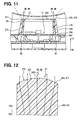
- the light shielding effect by the light shielding wall 375 collects the output light OB towards the light output direction OD in which the light output end face 362 faces. This can reduce the light which leaks towards an outside of the light shielding cylindrical body 175; the luminance of the ambient-light luminous region 13 becomes difficult to be visible from an outside of the light shielding cylindrical body 175 (see the two-dot chain line of FIG. 11 ). Therefore, the ambient-light luminous region 13 can be suppressed from being reflected in the side window SW (refer to FIG. 1 ).
- the third embodiment provides a design where the inner periphery of the light shielding cylindrical body 175 provides a luminous display using the acrylic cylindrical body 360. Therefore, although the design is provided such that the display region 11 is surrounded by the light shielding cylindrical body 175 to prevent the leakage of the light, the design can reduce a sense of limitation to a viewer.
- the acrylic cylindrical body 360 may be referred to as a transmissive member.
- the light output end face 362 may be also referred to as a light output face.
- the light collection structure 370 may be also referred to as a light collection device or means.
- the light shielding wall 375 may be referred to as a standing wall.
- the outer peripheral shielding wall portion 377 may be referred to as an outer peripheral wall portion.
- the outer peripheral auxiliary wall portion 379 may be also referred to as a back-extension wall portion.
- the fourth embodiment provides a light collection structure 470 including a refractive face 471 formed to be integrated with a light output end face 462.
- the light collection structure 470 eliminates a constituent element equivalent to the light shielding wall 75 (refer to FIG. 6 ) of the first embodiment.
- a refractive face 471 of the light collection structure 470 is explained in detail.
- the refractive face 471 forms a convex lens portion 472 to be convex that is protruded in the light output direction OD in a cross-section along a radial direction of an acrylic cylindrical body 460.
- the convex lens portion 472 is provided smoothly to range continuously from a boundary portion in an inner periphery to a boundary portion in an outer periphery.
- the refractive face 471 refracts the light guided by a transmissive wall portion 461 towards the light output direction OD.
- the light output direction OD in the fourth embodiment is defined, like in the first embodiment, as a direction of a normal line of a central portion 462c of a light output end face 462 in the cross-section along a radial direction.
- the direction of the normal line is the direction in which the central portion 462c faces.
- the refractive face 471 provides a refractive effect which collects the output light OB towards the light output direction OD so as to collect the output light OB, which is going to diffuse, towards the light output direction OD.
- the light collection structure 470 including the refractive face 471 provides a refraction effect to collect the output light OB towards the light output direction OD. This enables the reduction of the light which leaks in a direction different from the light output direction OD, and, simultaneously, the improvement of a luminance of the ambient-light luminous region 13. This configuration enables the ambient-light luminous region 13 to output light with a high luminance while helping prevent the ambient-light luminous region 13 from being reflected.
- the acrylic cylindrical body 460 and the ambient-light guide body 50 may be also referred to as a transmissive member.
- the light output end face 462 may be also referred to as a light output face.
- the light collection structure 470 may be also referred to as a light collection device or means.
- the fifth embodiment provides a light collection structure 570 that includes a light shielding wall 575 substantially identical to the light shielding wall 75 (refer to FIG. 6 ) of the first embodiment, and a refractive face 571 formed to be integrated into a light output end face 562.
- the light collection structure 570 will be explained in detail.
- the refractive face 571 is formed to project towards the front direction FD at a central portion in a cross-section along a radial direction of the acrylic cylindrical body 560.
- the refractive face 571 includes an inner slope portion 574a on the side of the inner periphery and an outer slope portion 574b on the side of the outer periphery. Both the slope portions 574a and 574b refracts the light guided by a transmissive wall portion 561 towards the light output direction OD.
- the light output direction OD in the fifth embodiment is defined as the direction of the normal line at a summit portion 562c between both the slope portions 574a and 574b.
- the refractive face 571 provides a refractive effect to collect the output light OB, which is going to diffuse or spread, towards the light output direction OD.
- the output light OB is collected towards the light output direction OD by a combination of the refractive effect by the refractive face 571 and the light shielding effect by the light shielding wall 575.
- This enables the reduction of the light which leaks in a direction different from the light output direction OD, and, simultaneously, the improvement of a luminance of the ambient-light luminous region 13.
- This configuration enables the ambient-light luminous region 13 to output light with a high luminance while helping prevent the ambient-light luminous region 13 from being reflected.
- the acrylic cylindrical body 560 and the arribient-light guide body 50 may be also referred to as a transmissive member.
- the light output end face 562 may be also referred to as a light output face.
- the light collection structure 570 may be also referred to as a light collection device or means.
- the light shielding wall 575 may be referred to as a standing wall.
- the light collection structure 670 in the sixth embodiment includes a light shielding wall 675 substantially identical to the light shielding wall 75 (refer to FIG. 6 ) of the first embodiment.
- the light collection structure 670 according to the sixth embodiment eliminates a constituent element equivalent to the refractive face 71 (refer to FIG. 6 ) of the first embodiment.
- the light output end face 662 is formed in a flat face facing the front direction FD.
- the light shielding effect by the light shielding wall 675 collects the output light OB towards the light output direction OD which the light output end face 662 faces. This enables the reduction of the light which leaks in a direction different from the light output direction OD, and, simultaneously, the improvement of a luminance of the ambient-light luminous region 13.
- This configuration enables the ambient-light luminous region 13 to output light with a high luminance while helping prevent the ambient-light luminous region 13 from being reflected.
- the acrylic cylindrical body 660 and the ambient-light guide body 50 may be also referred to as a transmissive member.
- the light output end face 662 may be also referred to as a light output face.
- the light collection structure 670 may be also referred to as a light collection device or means.
- the light shielding wall 675 may be referred to as a standing wall.
- dividing the convex lens portion 72 forms the refractive face 71 having a thinned Fresnel lens shape.
- the second embodiment provides the refractive face 271 having a Fresnel lens shape including a plurality of slope portions 271a.
- the slope portions according to the fifth embodiment may be divided into a plurality of sub-portions to be arranged along a reference plane orthogonal to the light output direction OD; thereby, the refractive face may be provided to have a smaller thickness.
- this convex lens portion may be divided into much more sub-portions rather than the first embodiment.
- the light collection structure is provided to have a circular-ring shape to surround the whole of the ambient-light luminous region 13.
- the refractive face and the light shielding wall which are included in the light collection structure may be formed in a part of the ambient-light luminous region 13.
- the light collection structure may be formed only in a lower part (near "km/h” in FIG. 1 ) of the display region 11.
- the light collection structure may be formed only in a portion at diagonally upward right close to the side window SW (near "120" and "140" in FIG. 1 ).
- the ambient-light luminous region 13 is formed in the circular-ring shape along the outer periphery of the display region 11.
- the shape of the ambient-light luminous region may be changed suitably.
- the ambient-light luminous region may have a shape formed by a plurality of straight lines to surround the display region 11.
- the ambient-light luminous region has a non-fully-circular ring shape to contain an interrupted portion.
- the light output direction OD of the output light OB is specified in the direction along the front direction or display direction FD.
- the light output direction OD or the direction in which the light output end face faces may be change suitably within a scope to suppress the ambient-light luminous region from being reflected to a rearview mirror or a side window.
- the light emitted from the ambient light source is guided by the ambient-light guide body to enter the acrylic cylindrical body.
- a light guide manner may be used which permits an ambient light source located directly under an acrylic cylindrical body in the back direction BD to emit light directly entering the ambient-light cylindrical body.
- the transmissive member may be suitably configured as long as guiding light into a light output face forming an ambient-light luminous region.
- the heights from the reference plane RP of the respective shielding wall portions 76 and 77 are identical to each other.
- the height of each shielding wall portion may adjusted suitably so as not to permit the light leaking from a luminous region to reach a rearview mirror or side window depending on the position relation of the luminous region and the rearview mirror or side window.
- the height of an outer peripheral shielding wall portion may be provided to be higher than the height of an inner peripheral shielding wall portion.
- either of an inner peripheral shielding wall portion or outer peripheral shielding wall portion may be omitted.
- a shielding wall portion may be interrupted partially.
- each auxiliary wall portion 78 and 79 is extended from each shielding wall portion 76 and 77 in the back direction BD, respectively.
- such an auxiliary wall portion may be omitted.
- each auxiliary wall portion may be provided to extend along a transmissive wall portion in the back direction BD to reach a light input end face.
- the light amount of light emitted from the ambient light source 43 is varied depending on the luminance in vicinity of the vehicle based on the state information of the headlight.
- the light amount by the ambient light source 43 or the luminous intensity of the ambient-light luminous region 13 may be set constant irrespective of the luminance in vicinity of the vehicle.
- the combination meter 100 may further include a constituent element equivalent to a light control sensor 97.
- the meter control circuit acquiring an output of the light control sensor may change continuously the light amount of the light emitted from the ambient light source depending on the luminance in vicinity.
- the refractive face 71 is formed to be integrated with the light output end face 62.
- the refractive face and the light output end face may be formed independently.
- a lens having a refractive face providing a light collection function may be arranged to be separate from a light output end face, in the light output direction OD.
- the lens may be supported by a light shielding wall standing from the light output end face, for instance.
- an embodiment of the present disclosure is applied to a speedometer displaying a travel speed of a vehicle in a combination meter mounted in the vehicle, for instance.
- the present disclosure may be applied to a tachometer, a fuel gauge, a water thermometer without need to be limited to the speedometer, for example.
- the present disclosure may be applied to a display apparatus generally used for various consumer appliances or various transport machines without need to be limited to a vehicular display apparatus.
Applications Claiming Priority (1)
| Application Number | Priority Date | Filing Date | Title |
|---|---|---|---|
| JP2013118143A JP5928411B2 (ja) | 2013-06-04 | 2013-06-04 | 車両用表示装置 |
Publications (2)
| Publication Number | Publication Date |
|---|---|
| EP2811264A1 true EP2811264A1 (de) | 2014-12-10 |
| EP2811264B1 EP2811264B1 (de) | 2017-07-05 |
Family
ID=50942556
Family Applications (1)
| Application Number | Title | Priority Date | Filing Date |
|---|---|---|---|
| EP14168073.6A Not-in-force EP2811264B1 (de) | 2013-06-04 | 2014-05-13 | Fahrzeuganzeigevorrichtung |
Country Status (4)
| Country | Link |
|---|---|
| US (1) | US9522630B2 (de) |
| EP (1) | EP2811264B1 (de) |
| JP (1) | JP5928411B2 (de) |
| CN (1) | CN104210362B (de) |
Families Citing this family (1)
| Publication number | Priority date | Publication date | Assignee | Title |
|---|---|---|---|---|
| JP6754644B2 (ja) * | 2016-09-06 | 2020-09-16 | 矢崎総業株式会社 | 車両表示装置 |
Citations (6)
| Publication number | Priority date | Publication date | Assignee | Title |
|---|---|---|---|---|
| JPH10332439A (ja) | 1997-05-28 | 1998-12-18 | Nippon Seiki Co Ltd | 計器装置 |
| EP1055916A2 (de) * | 1999-05-25 | 2000-11-29 | Denso Corporation | Beleuchtbares Zeigerinstrument |
| DE10025244A1 (de) * | 1999-05-25 | 2000-11-30 | Denso Corp | Meßgerät für ein Fahrzeug |
| EP1213565A1 (de) * | 2000-07-31 | 2002-06-12 | Nippon Seiki Co., Ltd. | Beleuchtungsvorrichtung |
| US7207117B1 (en) * | 2006-02-23 | 2007-04-24 | Denso International America, Inc. | Gauge with floodlighting, light ring, and hubless pointer |
| US20090223436A1 (en) * | 2008-03-05 | 2009-09-10 | Denso International America, Inc. | Three-dimensional lighted gauge |
Family Cites Families (23)
| Publication number | Priority date | Publication date | Assignee | Title |
|---|---|---|---|---|
| JPS6316975Y2 (de) * | 1980-03-19 | 1988-05-13 | ||
| JPS6316975A (ja) | 1986-07-05 | 1988-01-23 | Kobe Steel Ltd | 研削工具 |
| US5453939A (en) * | 1992-09-16 | 1995-09-26 | Caterpillar Inc. | Computerized diagnostic and monitoring system |
| JP2002048604A (ja) * | 2000-07-31 | 2002-02-15 | Nippon Seiki Co Ltd | 照明装置 |
| JP2004325829A (ja) * | 2003-04-25 | 2004-11-18 | Nippon Seiki Co Ltd | 照明装置 |
| CN100405019C (zh) * | 2003-07-17 | 2008-07-23 | 日本精机株式会社 | 指针式测量仪表 |
| US7278749B2 (en) * | 2005-01-06 | 2007-10-09 | Sullivan John T | Gauge with large illuminated gauge face |
| CN2866251Y (zh) * | 2005-08-17 | 2007-02-07 | 光阳工业股份有限公司 | 车辆仪表板装置 |
| JP4893451B2 (ja) * | 2006-06-06 | 2012-03-07 | 株式会社デンソー | 指針計器 |
| JP5210614B2 (ja) * | 2007-12-12 | 2013-06-12 | 矢崎総業株式会社 | 指針照明装置 |
| CN201272253Y (zh) * | 2008-08-20 | 2009-07-15 | 延锋伟世通汽车电子有限公司 | 汽车仪表指针的防漏光结构 |
| CN201284986Y (zh) * | 2008-10-22 | 2009-08-05 | 黄国进 | 一种具有集光结构的发光二极管模组及应用该模组的灯具 |
| DE102009011948A1 (de) * | 2009-03-10 | 2010-09-16 | GM Global Technology Operations, Inc., Detroit | Anzeigevorrichtung für ein Fahrzeug und Verfahren zur Herstellung der Anzeigevorrichtung |
| US8483907B2 (en) * | 2010-02-23 | 2013-07-09 | Paccar Inc | Customizable graphical display |
| CN102001310B (zh) * | 2010-11-05 | 2012-12-19 | 埃泰克汽车电子(芜湖)有限公司 | 一种汽车仪表照明结构 |
| CN102478676A (zh) * | 2010-11-30 | 2012-05-30 | 比亚迪股份有限公司 | 一种增光片及背光模组 |
| CN102095163B (zh) * | 2011-02-14 | 2013-08-21 | 中国科学院光电技术研究所 | 一种led整形一体化透镜 |
| JP5701668B2 (ja) * | 2011-04-22 | 2015-04-15 | 矢崎総業株式会社 | Led照明ユニット |
| JP5735851B2 (ja) * | 2011-04-28 | 2015-06-17 | 矢崎総業株式会社 | 指針装置及びこれを取り付けたメータ装置 |
| JP5816042B2 (ja) * | 2011-09-29 | 2015-11-17 | 矢崎総業株式会社 | 計器 |
| JP5816052B2 (ja) * | 2011-10-28 | 2015-11-17 | 矢崎総業株式会社 | 計器 |
| CN202675063U (zh) * | 2012-07-03 | 2013-01-16 | 威皇股份有限公司 | 侧光式背光模块 |
| CN103116197A (zh) * | 2013-01-31 | 2013-05-22 | 中国科学技术大学 | 一种具有短距匀光效果的单自由曲面厚透镜及其阵列 |
-
2013
- 2013-06-04 JP JP2013118143A patent/JP5928411B2/ja not_active Expired - Fee Related
-
2014
- 2014-05-13 EP EP14168073.6A patent/EP2811264B1/de not_active Not-in-force
- 2014-06-03 CN CN201410241462.2A patent/CN104210362B/zh active Active
- 2014-06-03 US US14/294,574 patent/US9522630B2/en active Active
Patent Citations (6)
| Publication number | Priority date | Publication date | Assignee | Title |
|---|---|---|---|---|
| JPH10332439A (ja) | 1997-05-28 | 1998-12-18 | Nippon Seiki Co Ltd | 計器装置 |
| EP1055916A2 (de) * | 1999-05-25 | 2000-11-29 | Denso Corporation | Beleuchtbares Zeigerinstrument |
| DE10025244A1 (de) * | 1999-05-25 | 2000-11-30 | Denso Corp | Meßgerät für ein Fahrzeug |
| EP1213565A1 (de) * | 2000-07-31 | 2002-06-12 | Nippon Seiki Co., Ltd. | Beleuchtungsvorrichtung |
| US7207117B1 (en) * | 2006-02-23 | 2007-04-24 | Denso International America, Inc. | Gauge with floodlighting, light ring, and hubless pointer |
| US20090223436A1 (en) * | 2008-03-05 | 2009-09-10 | Denso International America, Inc. | Three-dimensional lighted gauge |
Also Published As
| Publication number | Publication date |
|---|---|
| EP2811264B1 (de) | 2017-07-05 |
| US20140355236A1 (en) | 2014-12-04 |
| JP2014235128A (ja) | 2014-12-15 |
| JP5928411B2 (ja) | 2016-06-01 |
| CN104210362A (zh) | 2014-12-17 |
| CN104210362B (zh) | 2017-04-12 |
| US9522630B2 (en) | 2016-12-20 |
Similar Documents
| Publication | Publication Date | Title |
|---|---|---|
| US9041740B2 (en) | Vehicular display device and vehicular display system | |
| US4978214A (en) | Display apparatus for automotive vehicle | |
| JP5202495B2 (ja) | 車両用表示装置 | |
| JP2007108429A (ja) | 表示装置とそれを備えた車両用ヘッドアップディスプレイ装置 | |
| US8107165B2 (en) | Projector screen and display system | |
| EP2348291B1 (de) | Zeigerstruktur eines Instrumentenclusters | |
| JP6478009B2 (ja) | 表示装置 | |
| EP2811264B1 (de) | Fahrzeuganzeigevorrichtung | |
| JP2007121101A (ja) | 車両用指針計器 | |
| JP5348149B2 (ja) | 表示装置 | |
| US11714279B2 (en) | Vehicle display device | |
| JP5510076B2 (ja) | 表示装置 | |
| US20150183322A1 (en) | Display device for vehicle | |
| JP4952458B2 (ja) | 表示装置 | |
| JP6500621B2 (ja) | 表示装置 | |
| JP3613426B2 (ja) | 車両用計器装置の指針構造 | |
| JP2006118892A (ja) | 指針計器 | |
| JP5029521B2 (ja) | 車両用表示装置 | |
| JP5978841B2 (ja) | 表示装置 | |
| JP4583818B2 (ja) | 車両用表示装置 | |
| JP2006113024A (ja) | 指針計器 | |
| JP2006138725A (ja) | 指針と車両用指針計器 | |
| JP2006200947A (ja) | 車両用表示装置 | |
| JP2007114116A (ja) | 車両用指針計器 | |
| JP2021189032A (ja) | 表示装置 |
Legal Events
| Date | Code | Title | Description |
|---|---|---|---|
| PUAI | Public reference made under article 153(3) epc to a published international application that has entered the european phase |
Free format text: ORIGINAL CODE: 0009012 |
|
| 17P | Request for examination filed |
Effective date: 20140513 |
|
| AK | Designated contracting states |
Kind code of ref document: A1 Designated state(s): AL AT BE BG CH CY CZ DE DK EE ES FI FR GB GR HR HU IE IS IT LI LT LU LV MC MK MT NL NO PL PT RO RS SE SI SK SM TR |
|
| AX | Request for extension of the european patent |
Extension state: BA ME |
|
| RIN1 | Information on inventor provided before grant (corrected) |
Inventor name: KUNITACHI, RYO Inventor name: KAMON, SHINJI Inventor name: KOBAYASHI, YASUHIRO |
|
| R17P | Request for examination filed (corrected) |
Effective date: 20150326 |
|
| RBV | Designated contracting states (corrected) |
Designated state(s): AL AT BE BG CH CY CZ DE DK EE ES FI FR GB GR HR HU IE IS IT LI LT LU LV MC MK MT NL NO PL PT RO RS SE SI SK SM TR |
|
| 17Q | First examination report despatched |
Effective date: 20160321 |
|
| GRAP | Despatch of communication of intention to grant a patent |
Free format text: ORIGINAL CODE: EPIDOSNIGR1 |
|
| RIN1 | Information on inventor provided before grant (corrected) |
Inventor name: KOBAYASHI, YASUHIRO Inventor name: KUNITACHI, RYO Inventor name: KAMON, SHINJI |
|
| INTG | Intention to grant announced |
Effective date: 20161117 |
|
| RAP1 | Party data changed (applicant data changed or rights of an application transferred) |
Owner name: HONDA MOTOR CO., LTD. Owner name: DENSO CORPORATION |
|
| GRAS | Grant fee paid |
Free format text: ORIGINAL CODE: EPIDOSNIGR3 |
|
| RIN1 | Information on inventor provided before grant (corrected) |
Inventor name: KOBAYASHI, YASUHIRO Inventor name: KAMON, SHINJI Inventor name: KUNITACHI, RYO |
|
| GRAA | (expected) grant |
Free format text: ORIGINAL CODE: 0009210 |
|
| AK | Designated contracting states |
Kind code of ref document: B1 Designated state(s): AL AT BE BG CH CY CZ DE DK EE ES FI FR GB GR HR HU IE IS IT LI LT LU LV MC MK MT NL NO PL PT RO RS SE SI SK SM TR |
|
| REG | Reference to a national code |
Ref country code: GB Ref legal event code: FG4D |
|
| REG | Reference to a national code |
Ref country code: CH Ref legal event code: EP |
|
| REG | Reference to a national code |
Ref country code: AT Ref legal event code: REF Ref document number: 906913 Country of ref document: AT Kind code of ref document: T Effective date: 20170715 |
|
| REG | Reference to a national code |
Ref country code: IE Ref legal event code: FG4D |
|
| REG | Reference to a national code |
Ref country code: DE Ref legal event code: R096 Ref document number: 602014011411 Country of ref document: DE |
|
| REG | Reference to a national code |
Ref country code: NL Ref legal event code: MP Effective date: 20170705 |
|
| REG | Reference to a national code |
Ref country code: AT Ref legal event code: MK05 Ref document number: 906913 Country of ref document: AT Kind code of ref document: T Effective date: 20170705 |
|
| REG | Reference to a national code |
Ref country code: LT Ref legal event code: MG4D |
|
| PG25 | Lapsed in a contracting state [announced via postgrant information from national office to epo] |
Ref country code: FI Free format text: LAPSE BECAUSE OF FAILURE TO SUBMIT A TRANSLATION OF THE DESCRIPTION OR TO PAY THE FEE WITHIN THE PRESCRIBED TIME-LIMIT Effective date: 20170705 Ref country code: HR Free format text: LAPSE BECAUSE OF FAILURE TO SUBMIT A TRANSLATION OF THE DESCRIPTION OR TO PAY THE FEE WITHIN THE PRESCRIBED TIME-LIMIT Effective date: 20170705 Ref country code: SE Free format text: LAPSE BECAUSE OF FAILURE TO SUBMIT A TRANSLATION OF THE DESCRIPTION OR TO PAY THE FEE WITHIN THE PRESCRIBED TIME-LIMIT Effective date: 20170705 Ref country code: NO Free format text: LAPSE BECAUSE OF FAILURE TO SUBMIT A TRANSLATION OF THE DESCRIPTION OR TO PAY THE FEE WITHIN THE PRESCRIBED TIME-LIMIT Effective date: 20171005 Ref country code: AT Free format text: LAPSE BECAUSE OF FAILURE TO SUBMIT A TRANSLATION OF THE DESCRIPTION OR TO PAY THE FEE WITHIN THE PRESCRIBED TIME-LIMIT Effective date: 20170705 Ref country code: NL Free format text: LAPSE BECAUSE OF FAILURE TO SUBMIT A TRANSLATION OF THE DESCRIPTION OR TO PAY THE FEE WITHIN THE PRESCRIBED TIME-LIMIT Effective date: 20170705 Ref country code: LT Free format text: LAPSE BECAUSE OF FAILURE TO SUBMIT A TRANSLATION OF THE DESCRIPTION OR TO PAY THE FEE WITHIN THE PRESCRIBED TIME-LIMIT Effective date: 20170705 |
|
| PG25 | Lapsed in a contracting state [announced via postgrant information from national office to epo] |
Ref country code: BG Free format text: LAPSE BECAUSE OF FAILURE TO SUBMIT A TRANSLATION OF THE DESCRIPTION OR TO PAY THE FEE WITHIN THE PRESCRIBED TIME-LIMIT Effective date: 20171005 Ref country code: RS Free format text: LAPSE BECAUSE OF FAILURE TO SUBMIT A TRANSLATION OF THE DESCRIPTION OR TO PAY THE FEE WITHIN THE PRESCRIBED TIME-LIMIT Effective date: 20170705 Ref country code: PL Free format text: LAPSE BECAUSE OF FAILURE TO SUBMIT A TRANSLATION OF THE DESCRIPTION OR TO PAY THE FEE WITHIN THE PRESCRIBED TIME-LIMIT Effective date: 20170705 Ref country code: IS Free format text: LAPSE BECAUSE OF FAILURE TO SUBMIT A TRANSLATION OF THE DESCRIPTION OR TO PAY THE FEE WITHIN THE PRESCRIBED TIME-LIMIT Effective date: 20171105 Ref country code: GR Free format text: LAPSE BECAUSE OF FAILURE TO SUBMIT A TRANSLATION OF THE DESCRIPTION OR TO PAY THE FEE WITHIN THE PRESCRIBED TIME-LIMIT Effective date: 20171006 Ref country code: LV Free format text: LAPSE BECAUSE OF FAILURE TO SUBMIT A TRANSLATION OF THE DESCRIPTION OR TO PAY THE FEE WITHIN THE PRESCRIBED TIME-LIMIT Effective date: 20170705 Ref country code: ES Free format text: LAPSE BECAUSE OF FAILURE TO SUBMIT A TRANSLATION OF THE DESCRIPTION OR TO PAY THE FEE WITHIN THE PRESCRIBED TIME-LIMIT Effective date: 20170705 |
|
| REG | Reference to a national code |
Ref country code: DE Ref legal event code: R084 Ref document number: 602014011411 Country of ref document: DE |
|
| REG | Reference to a national code |
Ref country code: DE Ref legal event code: R097 Ref document number: 602014011411 Country of ref document: DE |
|
| PG25 | Lapsed in a contracting state [announced via postgrant information from national office to epo] |
Ref country code: CZ Free format text: LAPSE BECAUSE OF FAILURE TO SUBMIT A TRANSLATION OF THE DESCRIPTION OR TO PAY THE FEE WITHIN THE PRESCRIBED TIME-LIMIT Effective date: 20170705 Ref country code: DK Free format text: LAPSE BECAUSE OF FAILURE TO SUBMIT A TRANSLATION OF THE DESCRIPTION OR TO PAY THE FEE WITHIN THE PRESCRIBED TIME-LIMIT Effective date: 20170705 Ref country code: RO Free format text: LAPSE BECAUSE OF FAILURE TO SUBMIT A TRANSLATION OF THE DESCRIPTION OR TO PAY THE FEE WITHIN THE PRESCRIBED TIME-LIMIT Effective date: 20170705 |
|
| PLBE | No opposition filed within time limit |
Free format text: ORIGINAL CODE: 0009261 |
|
| STAA | Information on the status of an ep patent application or granted ep patent |
Free format text: STATUS: NO OPPOSITION FILED WITHIN TIME LIMIT |
|
| REG | Reference to a national code |
Ref country code: FR Ref legal event code: PLFP Year of fee payment: 5 |
|
| PG25 | Lapsed in a contracting state [announced via postgrant information from national office to epo] |
Ref country code: EE Free format text: LAPSE BECAUSE OF FAILURE TO SUBMIT A TRANSLATION OF THE DESCRIPTION OR TO PAY THE FEE WITHIN THE PRESCRIBED TIME-LIMIT Effective date: 20170705 Ref country code: SK Free format text: LAPSE BECAUSE OF FAILURE TO SUBMIT A TRANSLATION OF THE DESCRIPTION OR TO PAY THE FEE WITHIN THE PRESCRIBED TIME-LIMIT Effective date: 20170705 Ref country code: SM Free format text: LAPSE BECAUSE OF FAILURE TO SUBMIT A TRANSLATION OF THE DESCRIPTION OR TO PAY THE FEE WITHIN THE PRESCRIBED TIME-LIMIT Effective date: 20170705 Ref country code: IT Free format text: LAPSE BECAUSE OF FAILURE TO SUBMIT A TRANSLATION OF THE DESCRIPTION OR TO PAY THE FEE WITHIN THE PRESCRIBED TIME-LIMIT Effective date: 20170705 |
|
| 26N | No opposition filed |
Effective date: 20180406 |
|
| PG25 | Lapsed in a contracting state [announced via postgrant information from national office to epo] |
Ref country code: SI Free format text: LAPSE BECAUSE OF FAILURE TO SUBMIT A TRANSLATION OF THE DESCRIPTION OR TO PAY THE FEE WITHIN THE PRESCRIBED TIME-LIMIT Effective date: 20170705 |
|
| PGFP | Annual fee paid to national office [announced via postgrant information from national office to epo] |
Ref country code: DE Payment date: 20180522 Year of fee payment: 5 |
|
| REG | Reference to a national code |
Ref country code: CH Ref legal event code: PL |
|
| GBPC | Gb: european patent ceased through non-payment of renewal fee |
Effective date: 20180513 |
|
| REG | Reference to a national code |
Ref country code: BE Ref legal event code: MM Effective date: 20180531 |
|
| PG25 | Lapsed in a contracting state [announced via postgrant information from national office to epo] |
Ref country code: MC Free format text: LAPSE BECAUSE OF FAILURE TO SUBMIT A TRANSLATION OF THE DESCRIPTION OR TO PAY THE FEE WITHIN THE PRESCRIBED TIME-LIMIT Effective date: 20170705 |
|
| REG | Reference to a national code |
Ref country code: IE Ref legal event code: MM4A |
|
| PG25 | Lapsed in a contracting state [announced via postgrant information from national office to epo] |
Ref country code: LI Free format text: LAPSE BECAUSE OF NON-PAYMENT OF DUE FEES Effective date: 20180531 Ref country code: CH Free format text: LAPSE BECAUSE OF NON-PAYMENT OF DUE FEES Effective date: 20180531 |
|
| PG25 | Lapsed in a contracting state [announced via postgrant information from national office to epo] |
Ref country code: LU Free format text: LAPSE BECAUSE OF NON-PAYMENT OF DUE FEES Effective date: 20180513 |
|
| PG25 | Lapsed in a contracting state [announced via postgrant information from national office to epo] |
Ref country code: IE Free format text: LAPSE BECAUSE OF NON-PAYMENT OF DUE FEES Effective date: 20180513 Ref country code: GB Free format text: LAPSE BECAUSE OF NON-PAYMENT OF DUE FEES Effective date: 20180513 |
|
| PG25 | Lapsed in a contracting state [announced via postgrant information from national office to epo] |
Ref country code: BE Free format text: LAPSE BECAUSE OF NON-PAYMENT OF DUE FEES Effective date: 20180531 |
|
| PGFP | Annual fee paid to national office [announced via postgrant information from national office to epo] |
Ref country code: FR Payment date: 20190523 Year of fee payment: 6 |
|
| REG | Reference to a national code |
Ref country code: DE Ref legal event code: R119 Ref document number: 602014011411 Country of ref document: DE |
|
| PG25 | Lapsed in a contracting state [announced via postgrant information from national office to epo] |
Ref country code: MT Free format text: LAPSE BECAUSE OF NON-PAYMENT OF DUE FEES Effective date: 20180513 |
|
| PG25 | Lapsed in a contracting state [announced via postgrant information from national office to epo] |
Ref country code: TR Free format text: LAPSE BECAUSE OF FAILURE TO SUBMIT A TRANSLATION OF THE DESCRIPTION OR TO PAY THE FEE WITHIN THE PRESCRIBED TIME-LIMIT Effective date: 20170705 |
|
| PG25 | Lapsed in a contracting state [announced via postgrant information from national office to epo] |
Ref country code: DE Free format text: LAPSE BECAUSE OF NON-PAYMENT OF DUE FEES Effective date: 20191203 |
|
| PG25 | Lapsed in a contracting state [announced via postgrant information from national office to epo] |
Ref country code: PT Free format text: LAPSE BECAUSE OF FAILURE TO SUBMIT A TRANSLATION OF THE DESCRIPTION OR TO PAY THE FEE WITHIN THE PRESCRIBED TIME-LIMIT Effective date: 20170705 Ref country code: HU Free format text: LAPSE BECAUSE OF FAILURE TO SUBMIT A TRANSLATION OF THE DESCRIPTION OR TO PAY THE FEE WITHIN THE PRESCRIBED TIME-LIMIT; INVALID AB INITIO Effective date: 20140513 |
|
| PG25 | Lapsed in a contracting state [announced via postgrant information from national office to epo] |
Ref country code: MK Free format text: LAPSE BECAUSE OF NON-PAYMENT OF DUE FEES Effective date: 20170705 Ref country code: CY Free format text: LAPSE BECAUSE OF FAILURE TO SUBMIT A TRANSLATION OF THE DESCRIPTION OR TO PAY THE FEE WITHIN THE PRESCRIBED TIME-LIMIT Effective date: 20170705 |
|
| PG25 | Lapsed in a contracting state [announced via postgrant information from national office to epo] |
Ref country code: AL Free format text: LAPSE BECAUSE OF FAILURE TO SUBMIT A TRANSLATION OF THE DESCRIPTION OR TO PAY THE FEE WITHIN THE PRESCRIBED TIME-LIMIT Effective date: 20170705 |
|
| PG25 | Lapsed in a contracting state [announced via postgrant information from national office to epo] |
Ref country code: FR Free format text: LAPSE BECAUSE OF NON-PAYMENT OF DUE FEES Effective date: 20200531 |