EP2811193B1 - Structure d'arbre pour une boîte de vitesse - Google Patents
Structure d'arbre pour une boîte de vitesse Download PDFInfo
- Publication number
- EP2811193B1 EP2811193B1 EP14169515.5A EP14169515A EP2811193B1 EP 2811193 B1 EP2811193 B1 EP 2811193B1 EP 14169515 A EP14169515 A EP 14169515A EP 2811193 B1 EP2811193 B1 EP 2811193B1
- Authority
- EP
- European Patent Office
- Prior art keywords
- shaft
- fixed gear
- section
- hollow shaft
- fixed
- Prior art date
- Legal status (The legal status is an assumption and is not a legal conclusion. Google has not performed a legal analysis and makes no representation as to the accuracy of the status listed.)
- Active
Links
Images
Classifications
-
- F—MECHANICAL ENGINEERING; LIGHTING; HEATING; WEAPONS; BLASTING
- F16—ENGINEERING ELEMENTS AND UNITS; GENERAL MEASURES FOR PRODUCING AND MAINTAINING EFFECTIVE FUNCTIONING OF MACHINES OR INSTALLATIONS; THERMAL INSULATION IN GENERAL
- F16D—COUPLINGS FOR TRANSMITTING ROTATION; CLUTCHES; BRAKES
- F16D1/00—Couplings for rigidly connecting two coaxial shafts or other movable machine elements
- F16D1/06—Couplings for rigidly connecting two coaxial shafts or other movable machine elements for attachment of a member on a shaft or on a shaft-end
- F16D1/08—Couplings for rigidly connecting two coaxial shafts or other movable machine elements for attachment of a member on a shaft or on a shaft-end with clamping hub; with hub and longitudinal key
- F16D1/0852—Couplings for rigidly connecting two coaxial shafts or other movable machine elements for attachment of a member on a shaft or on a shaft-end with clamping hub; with hub and longitudinal key with radial clamping between the mating surfaces of the hub and shaft
- F16D1/0858—Couplings for rigidly connecting two coaxial shafts or other movable machine elements for attachment of a member on a shaft or on a shaft-end with clamping hub; with hub and longitudinal key with radial clamping between the mating surfaces of the hub and shaft due to the elasticity of the hub (including shrink fits)
-
- F—MECHANICAL ENGINEERING; LIGHTING; HEATING; WEAPONS; BLASTING
- F16—ENGINEERING ELEMENTS AND UNITS; GENERAL MEASURES FOR PRODUCING AND MAINTAINING EFFECTIVE FUNCTIONING OF MACHINES OR INSTALLATIONS; THERMAL INSULATION IN GENERAL
- F16C—SHAFTS; FLEXIBLE SHAFTS; ELEMENTS OR CRANKSHAFT MECHANISMS; ROTARY BODIES OTHER THAN GEARING ELEMENTS; BEARINGS
- F16C3/00—Shafts; Axles; Cranks; Eccentrics
- F16C3/02—Shafts; Axles
-
- F—MECHANICAL ENGINEERING; LIGHTING; HEATING; WEAPONS; BLASTING
- F16—ENGINEERING ELEMENTS AND UNITS; GENERAL MEASURES FOR PRODUCING AND MAINTAINING EFFECTIVE FUNCTIONING OF MACHINES OR INSTALLATIONS; THERMAL INSULATION IN GENERAL
- F16H—GEARING
- F16H57/00—General details of gearing
- F16H57/0018—Shaft assemblies for gearings
- F16H57/0025—Shaft assemblies for gearings with gearing elements rigidly connected to a shaft, e.g. securing gears or pulleys by specially adapted splines, keys or methods
-
- F—MECHANICAL ENGINEERING; LIGHTING; HEATING; WEAPONS; BLASTING
- F16—ENGINEERING ELEMENTS AND UNITS; GENERAL MEASURES FOR PRODUCING AND MAINTAINING EFFECTIVE FUNCTIONING OF MACHINES OR INSTALLATIONS; THERMAL INSULATION IN GENERAL
- F16H—GEARING
- F16H2700/00—Transmission housings and mounting of transmission components therein; Cooling; Lubrication; Flexible suspensions, e.g. floating frames
- F16H2700/02—Transmissions, specially for working vehicles
Definitions
- the present invention relates to a shaft assembly for a transmission, comprising a shaft and a fixed to the shaft by means of a shaft-hub connection Festradanix having a fixed gear and a hollow shaft portion, wherein the fixed wheel has a first axial side, a second axial side and a toothing, wherein the hollow shaft portion surrounds the shaft and extends from the first axial side of the fixed wheel.
- a shaft arrangement is from the DE102010023161A known.
- the present invention relates to a vehicle transmission with a shaft and at least one fixed thereto fixed wheel, which is for establishing a gear stage of the vehicle transmission with a loose wheel engaged, which is rotatably mounted on another shaft.
- the idler gear is in this case connectable by means of a clutch with the associated shaft or separable therefrom to insert or interpret the associated gear ratio.
- the clutch may be a synchronous clutch, in particular with lock synchronization.
- a vehicle transmission of this type generally has a plurality of gear stages, which are each formed by a wheel set. It is also known to connect a fixed wheel with two loose wheels, so that the fixed gear can be assigned to two gear ratios (so-called double use).
- shaft-hub connections For fixed connection of a fixed wheel with a shaft, various types of shaft-hub connections are known. On the one hand, it is known to press a single fixed wheel by means of a cylindrical press fit on a shaft section. Alternatively, it is known to form a spline on the inner circumference of the fixed wheel and on the outer circumference of a shaft portion, which can be flank-centered or head-centered. Finally, it is known to weld a fixed wheel to a shaft section, for example by means of rake welding or laser welding. In some shaft-hub connections an axial securing is required to fix the fixed wheel in the axial direction of the shaft. The joining area (press fit or spline) extends here usually over the entire axial length of the fixed wheel.
- the shaft-hub connections are formed in this area preferably substantially rotationally symmetrical.
- Non-rotationally symmetric shaft-hub connections for example by means of a feather key, usually lead to local voltage peaks, so that the components involved must be made very solid.
- a main connection section is understood to be that section of the shaft-hub connection via which a torque between shaft and fixed wheel is mainly transmitted.
- the axial spacing of the main connecting portion from the second axial side of the fixed wheel and / or from the hollow shaft end ensures that this main connecting portion has a smaller influence on adjacent components. This makes it possible to mount such components directly adjacent to the Festradanowski on the shaft, which are to be manufactured with high precision.
- the measure has the advantage that, where appropriate, the influence of the shaft-hub connection on the toothing of the fixed wheel of the fixed gear arrangement is lower, so that the service life can be increased.
- the main connecting portion can be manufactured inexpensively, with a minimum of labor.
- the main connection section may be based on a per se known technology, which involves the lowest possible risks during production, assembly and operation.
- the main connecting portion sets the fixed wheel assembly in this case fixed to the shaft in the circumferential direction, and preferably also in the axial direction. It is particularly preferred if the main connection section is adapted to be able to transmit axial, radial and circumferential forces.
- the hollow shaft section has a hollow shaft end remote from the fixed wheel, wherein the hollow shaft end is fixedly connected to a further fixed wheel on the outer circumference.
- the fixed wheel assembly thus includes two fixed wheels, which are interconnected via the hollow shaft portion.
- the main connecting portion is preferably in the axial direction between the two fixed wheels.
- the main connecting portion is preferably at least half the axial length and in particular at least the entire axial length of the fixed wheel from the second axial side of the fixed wheel and / or the hollow shaft end spaced. If a fixed gear has a relatively large diameter compared to the shaft-hub connection diameter, the main connection section can also partially overlap in the axial direction with the fixed wheel. However, in this case as well, it is preferable that the main connection portion is spaced from the respective end of the fixed gear assembly by at least half the axial length of the fixed gear.
- the main connection portion is formed by a main press-fitting portion.
- the main press-fit portion can be realized with a high degree of excess so that high forces are transferable without resulting in undue deformations adjacent the fixed-wheel assembly (FIG. on the shaft or on a component connected to the shaft).
- the shaft-hub connection has at least one sub connection portion formed in the axial direction between the main connection portion and one end of the fixed gear assembly, the main connection portion having a higher torque transmission capability than the sub connection portion.
- the sub connection portion can transmit a torque but a lower torque than the main connection portion.
- the main connection section is formed by a main press-fit section
- the secondary connection section is formed by a secondary press-fit section and wherein the main press-fit section has a greater oversize than the secondary press-fit section.
- both the main and the Maupresspassungsabites each have an excess, so are formed as a press fit and can therefore transmit torque. Due to the measure, the main press-fitting section With a larger excess, the main press-fit portion may have higher torque-transmitting capability than the sub-press-fit portion.
- a transition between the main press-fitting portion and the sub-press-fitting portion may be formed in stages. However, the transition can also be formed continuously. In the latter case, different press-fitting diameters can merge into one another via a continuous connection.
- the different excess dimensions can be formed on the inner circumference of the Festradanix. It is particularly preferred, however, if the different excess dimensions are formed on the outer circumference of a portion of the shaft on which the Festradanix is to be pressed.
- a fixed gear toothing is formed on the shaft, wherein the fixed wheel assembly axially adjacent to the fixed gear teeth.
- the fixed gear teeth of the shaft may be formed integrally with the shaft.
- a bearing component such as a bearing bush or a needle bearing or the like, axially disposed directly adjacent to the Festradanix.
- the directly adjacent arrangement of a fixed-gear toothing and / or a bearing component on the Festradan eleven is also made possible in that the main connecting portion is axially spaced from the ends of the Festradan eleven, so that no undue stress by the shaft-hub connection on directly adjacent components how the fixed gear teeth or the bearing component are exercised.
- the fixed wheel assembly can be made in one piece from a blank, for example, by machining processes.
- the fixed gear assembly is made of a first Festradabrough with a first axially projecting hollow shaft section and a second Festradabrough with a second axially projecting hollow shaft section, wherein the first and the second hollow shaft section are connected by a peripheral connection firmly together.
- the peripheral connection may in particular be a cohesive connection, which may be formed for example by rake welding.
- the fixed gear assembly is formed of a first fixed gear portion having an axially projecting hollow shaft portion and a fixed gear which is fixedly connected to an outer peripheral portion of the hollow shaft portion via a fixed gear.
- the fixed gear can be, for example, a welded joint.
- the excess of a main interference fit portion is preferably at least 25%, and more preferably at least 40% greater than the excess interference fit portion.
- the external teeth of the fixed wheel can transmit more torque or is more resilient.
- the main press-fit portion in the axial center of the fixed gear assembly allows a needle bearing seat to abut directly against the fixed wheel assembly.
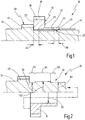
- a first embodiment of a shaft assembly is shown schematically in longitudinal section and generally designated 10.
- the shaft assembly 10 has a shaft 12, which may be a solid shaft or a hollow shaft. Furthermore, the shaft assembly 10 includes a fixed wheel assembly 14.
- the Festradan extract 14 has a first fixed wheel 16 with a first fixed gear teeth 18 on the outer circumference. Furthermore, the first fixed wheel 16 has a first axial side 20 and a second axial side 22.
- the fixed gear assembly 14 further includes a hollow shaft portion 24 extending from the first axial side 20 of the first fixed gear 16 in the axial direction.
- the axial length of the hollow shaft portion 24 is preferably at least as large as the axial length of the first fixed wheel 16, and preferably less than four times the axial length of the fixed wheel 16.
- a hollow shaft end of the hollow shaft portion 24 which is spaced from the first fixed wheel 16, with 26 denotes.
- the Festradan extract 14 is connected by means of a shaft-hub connection 30 with the shaft 12.
- the shaft-hub connection 30 has a main connection portion 32, which is preferably formed as a main press-fitting portion. Via the main connecting portion 32, the fixed wheel assembly 14 is fixed to the shaft 12 both in the circumferential direction and in the axial direction.
- the main connecting portion 32 is axially spaced from the second axial side 22 of the first fixed wheel 16, as shown at 34. Further, the main connection portion 32 is axially spaced from the hollow shaft end 26 in the axial direction, as indicated at 36.
- the distances 34, 36 are preferably at least half as large as the axial length of the fixed wheel 16.
- the main connecting portion 32 is formed so that it is not under the fixed gear teeth 18 is arranged, so that in the representation of the Fig. 1 the first distance 34 is at least as large as the axial length of the fixed wheel 16.
- a second fixed gear 40 with a second fixed-gear toothing 42 is formed on the shaft 12.
- the second fixed gear 40 is in this case formed integrally with the shaft 12.
- a bearing member 44 for example in the form of a bearing bush or in the form of a needle bearing, is arranged.
- the shaft-hub connection 30 is not to undue increases in voltage in the region of the adjacent components (that is, the second fixed wheel 40th and / or the bearing component 44) leads.
- the fixed gear assembly 14 it is possible to arrange the fixed gear assembly 14 directly adjacent to these components.
- Fig. 2 shows the realization of the main connection portion 32 by means of a main interference fit portion.
- Fig. 2 schematically shows that the fixed wheel assembly 14 has a continuous uniform inner radius 50.
- the shaft 12 has, in the area of the main press-fitting section 32, an outer radius 52 which is realized with an excess in relation to the inner radius 50.
- the shaft-hub connection 30 further includes a first sub-connection portion 54 in the form of a sub-interference fit portion.
- the shaft 12 has an outer radius 56, which is also made with excess over the inner radius 50.
- the shaft-hub connection 30 has, in the region of the second distance 36, a second auxiliary connection section 58, in which the shaft 12 has an outer radius 60, which is also preferably produced with an oversize relative to the inner diameter 50.
- the excess of the outer radius 52 of the main interference fit portion 32 is greater than the excess of the outer radii 56, 60 of the Maupresspassungsabitese 54, 58th
- Fig. 2 is also shown schematically by an arrow that the Festradan eleven 14 is pushed in the axial direction of the shaft 12 and then pressed in the region of the shaft-hub connection 30, wherein the second fixed wheel 40 may be disposed immediately adjacent to the second axial side 22 , or can serve as a stop when pressing.
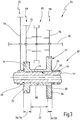
- Fig. 3 shows in schematic form a vehicle transmission 64, which is designed as a countershaft transmission in Stirnradbauweise.
- the vehicle transmission 64 has a shaft arrangement 10 ', which in terms of construction and operation of the shaft assembly 10 of the Fig. 1 and 2 equivalent.
- the same elements are therefore identified by the same reference numerals. The following section essentially explains the differences.
- the vehicle transmission 64 has a further shaft 66, which is arranged offset parallel to the shaft 12 '. Furthermore, the vehicle transmission 64 has a plurality of wheelsets, including a wheelset 68, which may be designed, for example, for a gear 3, a wheelset 70, which may be formed for example for a gear 5, and a gear set 72, for example, for a gear 1 may be formed.
- a wheelset 68 which may be designed, for example, for a gear 3
- a wheelset 70 which may be formed for example for a gear 5
- a gear set 72 for example, for a gear 1
- the wheelset 68 has a loose wheel 74 which is rotatably mounted on the further shaft 66.
- the wheel set 70 has a loose wheel 76, which is rotatably mounted on the further shaft 66.
- the wheel set 72 has a loose wheel 78, which is rotatably mounted on the further shaft 66.
- a clutch pack 80 is disposed on the further shaft 66, by means of which a neutral position can be set, and two switch positions in which either the idler gear 74 rotatably connected to the other shaft 66, or the idler gear 76th Clutch packages 80 of this type are well known.
- the clutch pack 80 may include, for example, synchronizer clutches.
- the idler gear 74 of the wheelset 68 is in rotational engagement with the first fixed gear 16.
- the idler gear 78 of the wheelset 72 is in rotary engagement with the second fixed gear 40th
- the third fixed gear 84 is disposed on the outer circumference of the hollow shaft portion 24 adjacent to the hollow shaft end 26.
- One axial side of the third fixed gear 84 is preferably axially aligned with the hollow shaft end 26.
- the fixed wheel assembly 14 ' is connected via a shaft-hub connection 30 to the shaft 12', which also has a main connection portion 32 and two auxiliary connection portions 54, 58.
- the auxiliary connection portion 54 is from the second axial side 22 of FIG first fixed wheel 16 further apart than the axial length of the first fixed wheel 16.
- the main connecting portion 32 is spaced from the hollow shaft end 26 by at least half the axial length of the third fixed wheel 84.
- the Festradan elbow 14 ' may be made in one piece from a blank.
- the Festradan eleven ' may be formed from a first Festradabrough with a first axially projecting hollow shaft section and from a second Festradabites with a second axially projecting hollow shaft section, wherein the hollow shaft section to form the hollow shaft portion 24 are fixedly connected to each other by a peripheral connection, as indicated schematically at 86.
- the peripheral connection may for example be a welded joint.
- the fixed wheel assembly 14 may also be formed by a hollow shaft portion which may be connected via two fixed-wheel connections with respective fixed wheels. In the latter case, the blanks can be made easier.
Landscapes
- Engineering & Computer Science (AREA)
- General Engineering & Computer Science (AREA)
- Mechanical Engineering (AREA)
- Ocean & Marine Engineering (AREA)
- Gears, Cams (AREA)
- General Details Of Gearings (AREA)
Claims (10)
- Ensemble d'arbre (10) pour transmission (64), présentant un arbre (12) et un ensemble (14) de roue fixe qui présente une roue fixe (16) et une section (24) d'arbre creux et qui est fixé sur l'arbre (12) au moyen d'une liaison (30) arbre-moyeu,
la roue fixe (16) présentant un premier côté axial (20), un deuxième côté axial (22) ainsi qu'une denture (18),
la section (24) d'arbre creux entourant l'arbre (12) et s'étendant depuis le premier côté axial (20) de la roue fixe (16),
la section (24) d'arbre creux présentant une extrémité (26) d'arbre creux située à distance de la roue fixe (16),
la liaison (30) arbre-moyeu présentant une section principale de liaison (32) formée par une liaison principale (32) d'adaptation en compression maintenue à distance dans la direction axiale du deuxième côté axial (22) de la roue fixe (16),
caractérisé en ce que
la section principale de liaison (32) est située à distance de l'extrémité (26) de l'arbre creux. - Ensemble d'arbre selon la revendication 1, caractérisé en ce que la section (24) d'arbre creux présente une extrémité (26) d'arbre creux située à distance de la roue fixe (16) et en ce que l'extrémité (26) de l'arbre creux est reliée solidairement à une roue fixe (84) à sa périphérie extérieure.
- Ensemble d'arbre selon l'une des revendications 1 ou 2, caractérisé en ce que la liaison (30) arbre-moyeu présente au moins une section secondaire de liaison (54, 58), la section principale de liaison (32) présentant une capacité plus élevée de transfert de couple de rotation que la section secondaire de liaison (54, 58).
- Ensemble d'arbre selon la revendication 3, caractérisé en ce que la section principale de liaison (32) est formée par une section principale (32) d'adaptation en compression, la section secondaire de liaison (54, 58) étant formée par une section secondaire (54, 58) d'adaptation en compression, la section principale (32) d'adaptation en compression présentant des dimensions plus grandes que la section secondaire (54, 58) d'adaptation en compression.
- Ensemble d'arbre selon l'une des revendications 1 à 4, caractérisé en ce qu'une denture (42) de roue fixe est formée sur l'arbre (12), l'ensemble (14) de roue fixe étant adjacent axialement directement à la denture (42) de roue fixe.
- Ensemble d'arbre selon l'une des revendications 1 à 5, caractérisé en ce qu'un composant de palier (44) est directement adjacent dans la direction axiale à l'ensemble (14) de roue fixe.
- Ensemble d'arbre selon l'une des revendications 1 à 6, caractérisé en ce que l'ensemble (14) de roue fixe est réalisé d'un seul tenant à partir d'une ébauche.
- Ensemble d'arbre selon l'une des revendications 1 à 6, caractérisé en ce que l'ensemble (14) de roue fixe est constitué d'une première section de roue fixe présentant une première section partielle d'arbre creux en débord axial et d'une deuxième section de roue fixe présentant une deuxième section partielle d'arbre creux en débord axial, la première et la deuxième section partielle d'arbre creux étant reliées solidairement l'une à l'autre par une liaison périphérique (86).
- Ensemble d'arbre selon l'une des revendications 1 à 6, caractérisé en ce que l'ensemble (14) de roue fixe est formé d'une première section de roue fixe dotée d'une section (24) d'arbre creux en débord axial et d'une roue fixe (16) reliée solidairement à une section périphérique extérieure de la section (24) d'arbre creux par l'intermédiaire d'une liaison (88) de roue fixe.
- Transmission (64) pour véhicule présentant un arbre (12) sur lequel est fixée au moins une roue fixe (16) qui engage une roue folle (74) pour établir un rapport de la transmission (64) du véhicule et qui est monté à rotation sur un autre arbre (66), l'arbre (12) et la roue fixe (16) étant formés par un ensemble (10) d'arbre selon l'une des revendications 1 à 9.
Applications Claiming Priority (1)
| Application Number | Priority Date | Filing Date | Title |
|---|---|---|---|
| DE102013105915.5A DE102013105915A1 (de) | 2013-06-07 | 2013-06-07 | Wellenanordnung für ein Getriebe |
Publications (2)
| Publication Number | Publication Date |
|---|---|
| EP2811193A1 EP2811193A1 (fr) | 2014-12-10 |
| EP2811193B1 true EP2811193B1 (fr) | 2016-12-28 |
Family
ID=50774678
Family Applications (1)
| Application Number | Title | Priority Date | Filing Date |
|---|---|---|---|
| EP14169515.5A Active EP2811193B1 (fr) | 2013-06-07 | 2014-05-22 | Structure d'arbre pour une boîte de vitesse |
Country Status (4)
| Country | Link |
|---|---|
| EP (1) | EP2811193B1 (fr) |
| CN (1) | CN104235322B (fr) |
| DE (1) | DE102013105915A1 (fr) |
| ES (1) | ES2620493T3 (fr) |
Families Citing this family (3)
| Publication number | Priority date | Publication date | Assignee | Title |
|---|---|---|---|---|
| JP6706510B2 (ja) * | 2016-02-19 | 2020-06-10 | ナブテスコ株式会社 | 発電装置を駆動する駆動装置 |
| DE102017203773A1 (de) * | 2017-03-08 | 2018-09-13 | Bayerische Motoren Werke Aktiengesellschaft | Welle-Nabe-Verbindung, sowie Antriebsstrang mit einer solchen Welle-Nabe-Verbindung |
| CN114962596A (zh) * | 2022-07-27 | 2022-08-30 | 四川丹齿精工科技有限公司 | 一种高装机率的齿轮动力传递结构 |
Family Cites Families (7)
| Publication number | Priority date | Publication date | Assignee | Title |
|---|---|---|---|---|
| JPS58113659A (ja) * | 1981-12-26 | 1983-07-06 | Toyota Motor Corp | 自動車用歯車変速機における変速ギヤとシヤフトの固定構造 |
| SE515468C2 (sv) * | 1999-12-23 | 2001-08-13 | Volvo Lastvagnar Ab | Kugghjul avsett att med presspassning förbindas till en axel och en axel uppbärande ett presspassat kugghjul |
| DE10003923A1 (de) * | 2000-01-29 | 2001-08-02 | Zahnradfabrik Friedrichshafen | Verfahren zum Verbinden einer Nabe mit einer Welle |
| JP2002227866A (ja) * | 2001-01-31 | 2002-08-14 | Isuzu Motors Ltd | 圧入方法および圧入構造 |
| US8662785B2 (en) * | 2006-11-04 | 2014-03-04 | Zf Friedrichshafen Ag | Shaft-gear connection |
| DE102006052104A1 (de) * | 2006-11-04 | 2008-05-08 | Zf Friedrichshafen Ag | Welle-Zahnrad-Verbindung |
| DE102010023161A1 (de) * | 2010-06-09 | 2011-01-13 | Daimler Ag | Zahnradbaugruppe zum Aufpressen auf eine Welle |
-
2013
- 2013-06-07 DE DE102013105915.5A patent/DE102013105915A1/de not_active Withdrawn
-
2014
- 2014-05-22 EP EP14169515.5A patent/EP2811193B1/fr active Active
- 2014-05-22 ES ES14169515.5T patent/ES2620493T3/es active Active
- 2014-06-06 CN CN201410250537.3A patent/CN104235322B/zh active Active
Non-Patent Citations (1)
| Title |
|---|
| None * |
Also Published As
| Publication number | Publication date |
|---|---|
| ES2620493T3 (es) | 2017-06-28 |
| EP2811193A1 (fr) | 2014-12-10 |
| CN104235322B (zh) | 2017-01-04 |
| CN104235322A (zh) | 2014-12-24 |
| DE102013105915A1 (de) | 2014-12-11 |
Similar Documents
| Publication | Publication Date | Title |
|---|---|---|
| DE102019127242A1 (de) | Getriebe sowie Anordnung eines Getriebes und einer Elektromaschine | |
| EP2811193B1 (fr) | Structure d'arbre pour une boîte de vitesse | |
| DE102019125397B4 (de) | Getriebe sowie Kraftfahrzeug mit Getriebe | |
| DE3514578A1 (de) | Differentialgetriebe | |
| WO2011144329A1 (fr) | Agencement d'entraînement sur une boîte de vitesse à double embrayage pour véhicules automobiles | |
| DE102014223505A1 (de) | Welle-Nabe-Verbindung eines Doppelzahnrades auf einer Getriebewelle | |
| EP3882478B1 (fr) | Chaine cinématique avec un accouplement extensible entre un arbre moteur et un arbre d'entrée d'une boîte de vitesses | |
| DE102008049978A1 (de) | Schalteinheit mit Kupplungskörper | |
| EP3938681A1 (fr) | Différentiel | |
| DE2848288A1 (de) | Synchronisiereinrichtung fuer ein kfz-getriebe | |
| DE102019118187A1 (de) | Differenzialgetriebe | |
| EP3699442B1 (fr) | Arbre | |
| EP3482482B1 (fr) | Ensemble moteur électrique et procédé de montage d'un ensemble moteur électrique | |
| DE102019129236A1 (de) | Als Modulbaukasten aufgebauter Planetenträger | |
| EP1146243B1 (fr) | Ensemble de sychronisation pour embrayage de changement de vitesses | |
| DE102008063013B3 (de) | Differentialeinheit | |
| DE102018128799A1 (de) | Welle-Nabe-Verbindung für ein Getriebe mit einer Doppelkupplungsvorrichtung | |
| DE10213950A1 (de) | Hydrodynamische Kupplung, insbesondere Drehmomentwandler | |
| DE102019208626B3 (de) | Variable Kupplungsanordnung mit zwei konzentrisch angeordneten Kupplungen | |
| DE3022958A1 (de) | Keilwellenkupplung | |
| DE102017223304B4 (de) | Kraftfahrzeugantriebswelle und Verfahren zu deren Herstellung | |
| WO2009083054A1 (fr) | Boîte de vitesses | |
| EP4193071A1 (fr) | Unité d'entraînement pour véhicule | |
| EP3179138B1 (fr) | Dispositif et procédé de liaison de deux parties rotatives de machine | |
| DE102011119575B4 (de) | Verfahren zum Herstellen einer Losradanordnung |
Legal Events
| Date | Code | Title | Description |
|---|---|---|---|
| PUAI | Public reference made under article 153(3) epc to a published international application that has entered the european phase |
Free format text: ORIGINAL CODE: 0009012 |
|
| 17P | Request for examination filed |
Effective date: 20140522 |
|
| AK | Designated contracting states |
Kind code of ref document: A1 Designated state(s): AL AT BE BG CH CY CZ DE DK EE ES FI FR GB GR HR HU IE IS IT LI LT LU LV MC MK MT NL NO PL PT RO RS SE SI SK SM TR |
|
| AX | Request for extension of the european patent |
Extension state: BA ME |
|
| R17P | Request for examination filed (corrected) |
Effective date: 20150512 |
|
| RBV | Designated contracting states (corrected) |
Designated state(s): AL AT BE BG CH CY CZ DE DK EE ES FI FR GB GR HR HU IE IS IT LI LT LU LV MC MK MT NL NO PL PT RO RS SE SI SK SM TR |
|
| GRAP | Despatch of communication of intention to grant a patent |
Free format text: ORIGINAL CODE: EPIDOSNIGR1 |
|
| RIC1 | Information provided on ipc code assigned before grant |
Ipc: F16D 1/06 20060101AFI20160620BHEP Ipc: F16H 57/00 20120101ALI20160620BHEP |
|
| INTG | Intention to grant announced |
Effective date: 20160706 |
|
| GRAS | Grant fee paid |
Free format text: ORIGINAL CODE: EPIDOSNIGR3 |
|
| GRAA | (expected) grant |
Free format text: ORIGINAL CODE: 0009210 |
|
| AK | Designated contracting states |
Kind code of ref document: B1 Designated state(s): AL AT BE BG CH CY CZ DE DK EE ES FI FR GB GR HR HU IE IS IT LI LT LU LV MC MK MT NL NO PL PT RO RS SE SI SK SM TR |
|
| REG | Reference to a national code |
Ref country code: GB Ref legal event code: FG4D Free format text: NOT ENGLISH |
|
| REG | Reference to a national code |
Ref country code: CH Ref legal event code: EP |
|
| REG | Reference to a national code |
Ref country code: AT Ref legal event code: REF Ref document number: 857582 Country of ref document: AT Kind code of ref document: T Effective date: 20170115 |
|
| REG | Reference to a national code |
Ref country code: IE Ref legal event code: FG4D Free format text: LANGUAGE OF EP DOCUMENT: GERMAN |
|
| REG | Reference to a national code |
Ref country code: DE Ref legal event code: R096 Ref document number: 502014002303 Country of ref document: DE |
|
| PG25 | Lapsed in a contracting state [announced via postgrant information from national office to epo] |
Ref country code: LV Free format text: LAPSE BECAUSE OF FAILURE TO SUBMIT A TRANSLATION OF THE DESCRIPTION OR TO PAY THE FEE WITHIN THE PRESCRIBED TIME-LIMIT Effective date: 20161228 |
|
| RAP2 | Party data changed (patent owner data changed or rights of a patent transferred) |
Owner name: GETRAG B.V. & CO. KG |
|
| REG | Reference to a national code |
Ref country code: LT Ref legal event code: MG4D |
|
| PG25 | Lapsed in a contracting state [announced via postgrant information from national office to epo] |
Ref country code: LT Free format text: LAPSE BECAUSE OF FAILURE TO SUBMIT A TRANSLATION OF THE DESCRIPTION OR TO PAY THE FEE WITHIN THE PRESCRIBED TIME-LIMIT Effective date: 20161228 Ref country code: NO Free format text: LAPSE BECAUSE OF FAILURE TO SUBMIT A TRANSLATION OF THE DESCRIPTION OR TO PAY THE FEE WITHIN THE PRESCRIBED TIME-LIMIT Effective date: 20170328 Ref country code: SE Free format text: LAPSE BECAUSE OF FAILURE TO SUBMIT A TRANSLATION OF THE DESCRIPTION OR TO PAY THE FEE WITHIN THE PRESCRIBED TIME-LIMIT Effective date: 20161228 Ref country code: GR Free format text: LAPSE BECAUSE OF FAILURE TO SUBMIT A TRANSLATION OF THE DESCRIPTION OR TO PAY THE FEE WITHIN THE PRESCRIBED TIME-LIMIT Effective date: 20170329 |
|
| REG | Reference to a national code |
Ref country code: NL Ref legal event code: MP Effective date: 20161228 |
|
| REG | Reference to a national code |
Ref country code: FR Ref legal event code: PLFP Year of fee payment: 4 |
|
| PG25 | Lapsed in a contracting state [announced via postgrant information from national office to epo] |
Ref country code: RS Free format text: LAPSE BECAUSE OF FAILURE TO SUBMIT A TRANSLATION OF THE DESCRIPTION OR TO PAY THE FEE WITHIN THE PRESCRIBED TIME-LIMIT Effective date: 20161228 Ref country code: HR Free format text: LAPSE BECAUSE OF FAILURE TO SUBMIT A TRANSLATION OF THE DESCRIPTION OR TO PAY THE FEE WITHIN THE PRESCRIBED TIME-LIMIT Effective date: 20161228 Ref country code: FI Free format text: LAPSE BECAUSE OF FAILURE TO SUBMIT A TRANSLATION OF THE DESCRIPTION OR TO PAY THE FEE WITHIN THE PRESCRIBED TIME-LIMIT Effective date: 20161228 |
|
| REG | Reference to a national code |
Ref country code: ES Ref legal event code: FG2A Ref document number: 2620493 Country of ref document: ES Kind code of ref document: T3 Effective date: 20170628 |
|
| PG25 | Lapsed in a contracting state [announced via postgrant information from national office to epo] |
Ref country code: NL Free format text: LAPSE BECAUSE OF FAILURE TO SUBMIT A TRANSLATION OF THE DESCRIPTION OR TO PAY THE FEE WITHIN THE PRESCRIBED TIME-LIMIT Effective date: 20161228 |
|
| PG25 | Lapsed in a contracting state [announced via postgrant information from national office to epo] |
Ref country code: IS Free format text: LAPSE BECAUSE OF FAILURE TO SUBMIT A TRANSLATION OF THE DESCRIPTION OR TO PAY THE FEE WITHIN THE PRESCRIBED TIME-LIMIT Effective date: 20170428 Ref country code: RO Free format text: LAPSE BECAUSE OF FAILURE TO SUBMIT A TRANSLATION OF THE DESCRIPTION OR TO PAY THE FEE WITHIN THE PRESCRIBED TIME-LIMIT Effective date: 20161228 Ref country code: SK Free format text: LAPSE BECAUSE OF FAILURE TO SUBMIT A TRANSLATION OF THE DESCRIPTION OR TO PAY THE FEE WITHIN THE PRESCRIBED TIME-LIMIT Effective date: 20161228 Ref country code: CZ Free format text: LAPSE BECAUSE OF FAILURE TO SUBMIT A TRANSLATION OF THE DESCRIPTION OR TO PAY THE FEE WITHIN THE PRESCRIBED TIME-LIMIT Effective date: 20161228 Ref country code: EE Free format text: LAPSE BECAUSE OF FAILURE TO SUBMIT A TRANSLATION OF THE DESCRIPTION OR TO PAY THE FEE WITHIN THE PRESCRIBED TIME-LIMIT Effective date: 20161228 |
|
| PG25 | Lapsed in a contracting state [announced via postgrant information from national office to epo] |
Ref country code: LU Free format text: LAPSE BECAUSE OF NON-PAYMENT OF DUE FEES Effective date: 20170531 Ref country code: PL Free format text: LAPSE BECAUSE OF FAILURE TO SUBMIT A TRANSLATION OF THE DESCRIPTION OR TO PAY THE FEE WITHIN THE PRESCRIBED TIME-LIMIT Effective date: 20161228 Ref country code: PT Free format text: LAPSE BECAUSE OF FAILURE TO SUBMIT A TRANSLATION OF THE DESCRIPTION OR TO PAY THE FEE WITHIN THE PRESCRIBED TIME-LIMIT Effective date: 20170428 Ref country code: BG Free format text: LAPSE BECAUSE OF FAILURE TO SUBMIT A TRANSLATION OF THE DESCRIPTION OR TO PAY THE FEE WITHIN THE PRESCRIBED TIME-LIMIT Effective date: 20170328 Ref country code: SM Free format text: LAPSE BECAUSE OF FAILURE TO SUBMIT A TRANSLATION OF THE DESCRIPTION OR TO PAY THE FEE WITHIN THE PRESCRIBED TIME-LIMIT Effective date: 20161228 |
|
| REG | Reference to a national code |
Ref country code: DE Ref legal event code: R097 Ref document number: 502014002303 Country of ref document: DE |
|
| PLBE | No opposition filed within time limit |
Free format text: ORIGINAL CODE: 0009261 |
|
| STAA | Information on the status of an ep patent application or granted ep patent |
Free format text: STATUS: NO OPPOSITION FILED WITHIN TIME LIMIT |
|
| PG25 | Lapsed in a contracting state [announced via postgrant information from national office to epo] |
Ref country code: DK Free format text: LAPSE BECAUSE OF FAILURE TO SUBMIT A TRANSLATION OF THE DESCRIPTION OR TO PAY THE FEE WITHIN THE PRESCRIBED TIME-LIMIT Effective date: 20161228 |
|
| 26N | No opposition filed |
Effective date: 20170929 |
|
| REG | Reference to a national code |
Ref country code: CH Ref legal event code: PL |
|
| PG25 | Lapsed in a contracting state [announced via postgrant information from national office to epo] |
Ref country code: MC Free format text: LAPSE BECAUSE OF FAILURE TO SUBMIT A TRANSLATION OF THE DESCRIPTION OR TO PAY THE FEE WITHIN THE PRESCRIBED TIME-LIMIT Effective date: 20161228 |
|
| REG | Reference to a national code |
Ref country code: IE Ref legal event code: MM4A |
|
| PG25 | Lapsed in a contracting state [announced via postgrant information from national office to epo] |
Ref country code: LI Free format text: LAPSE BECAUSE OF NON-PAYMENT OF DUE FEES Effective date: 20170531 Ref country code: CH Free format text: LAPSE BECAUSE OF NON-PAYMENT OF DUE FEES Effective date: 20170531 Ref country code: SI Free format text: LAPSE BECAUSE OF FAILURE TO SUBMIT A TRANSLATION OF THE DESCRIPTION OR TO PAY THE FEE WITHIN THE PRESCRIBED TIME-LIMIT Effective date: 20161228 |
|
| PG25 | Lapsed in a contracting state [announced via postgrant information from national office to epo] |
Ref country code: LU Free format text: LAPSE BECAUSE OF NON-PAYMENT OF DUE FEES Effective date: 20170522 |
|
| REG | Reference to a national code |
Ref country code: BE Ref legal event code: MM Effective date: 20170531 |
|
| PG25 | Lapsed in a contracting state [announced via postgrant information from national office to epo] |
Ref country code: IE Free format text: LAPSE BECAUSE OF NON-PAYMENT OF DUE FEES Effective date: 20170522 |
|
| REG | Reference to a national code |
Ref country code: FR Ref legal event code: PLFP Year of fee payment: 5 |
|
| REG | Reference to a national code |
Ref country code: DE Ref legal event code: R081 Ref document number: 502014002303 Country of ref document: DE Owner name: MAGNA PT B.V. & CO. KG, DE Free format text: FORMER OWNER: GETRAG GETRIEBE- UND ZAHNRADFABRIK HERMANN HAGENMEYER GMBH & CIE KG, 74199 UNTERGRUPPENBACH, DE Ref country code: DE Ref legal event code: R082 Ref document number: 502014002303 Country of ref document: DE Representative=s name: RAUSCH, GABRIELE, DIPL.-PHYS. DR.RER.NAT., DE Ref country code: DE Ref legal event code: R081 Ref document number: 502014002303 Country of ref document: DE Owner name: GETRAG B.V. & CO. KG, DE Free format text: FORMER OWNER: GETRAG GETRIEBE- UND ZAHNRADFABRIK HERMANN HAGENMEYER GMBH & CIE KG, 74199 UNTERGRUPPENBACH, DE |
|
| PG25 | Lapsed in a contracting state [announced via postgrant information from national office to epo] |
Ref country code: BE Free format text: LAPSE BECAUSE OF NON-PAYMENT OF DUE FEES Effective date: 20170531 |
|
| PG25 | Lapsed in a contracting state [announced via postgrant information from national office to epo] |
Ref country code: MT Free format text: LAPSE BECAUSE OF FAILURE TO SUBMIT A TRANSLATION OF THE DESCRIPTION OR TO PAY THE FEE WITHIN THE PRESCRIBED TIME-LIMIT Effective date: 20161228 |
|
| REG | Reference to a national code |
Ref country code: DE Ref legal event code: R082 Ref document number: 502014002303 Country of ref document: DE Representative=s name: RAUSCH, GABRIELE, DIPL.-PHYS. DR.RER.NAT., DE Ref country code: DE Ref legal event code: R081 Ref document number: 502014002303 Country of ref document: DE Owner name: MAGNA PT B.V. & CO. KG, DE Free format text: FORMER OWNER: GETRAG B.V. & CO. KG, 74199 UNTERGRUPPENBACH, DE |
|
| PG25 | Lapsed in a contracting state [announced via postgrant information from national office to epo] |
Ref country code: HU Free format text: LAPSE BECAUSE OF FAILURE TO SUBMIT A TRANSLATION OF THE DESCRIPTION OR TO PAY THE FEE WITHIN THE PRESCRIBED TIME-LIMIT; INVALID AB INITIO Effective date: 20140522 |
|
| PG25 | Lapsed in a contracting state [announced via postgrant information from national office to epo] |
Ref country code: CY Free format text: LAPSE BECAUSE OF FAILURE TO SUBMIT A TRANSLATION OF THE DESCRIPTION OR TO PAY THE FEE WITHIN THE PRESCRIBED TIME-LIMIT Effective date: 20161228 |
|
| PG25 | Lapsed in a contracting state [announced via postgrant information from national office to epo] |
Ref country code: MK Free format text: LAPSE BECAUSE OF FAILURE TO SUBMIT A TRANSLATION OF THE DESCRIPTION OR TO PAY THE FEE WITHIN THE PRESCRIBED TIME-LIMIT Effective date: 20161228 |
|
| PG25 | Lapsed in a contracting state [announced via postgrant information from national office to epo] |
Ref country code: TR Free format text: LAPSE BECAUSE OF FAILURE TO SUBMIT A TRANSLATION OF THE DESCRIPTION OR TO PAY THE FEE WITHIN THE PRESCRIBED TIME-LIMIT Effective date: 20161228 |
|
| PG25 | Lapsed in a contracting state [announced via postgrant information from national office to epo] |
Ref country code: AL Free format text: LAPSE BECAUSE OF FAILURE TO SUBMIT A TRANSLATION OF THE DESCRIPTION OR TO PAY THE FEE WITHIN THE PRESCRIBED TIME-LIMIT Effective date: 20161228 |
|
| REG | Reference to a national code |
Ref country code: AT Ref legal event code: MM01 Ref document number: 857582 Country of ref document: AT Kind code of ref document: T Effective date: 20190522 |
|
| PG25 | Lapsed in a contracting state [announced via postgrant information from national office to epo] |
Ref country code: AT Free format text: LAPSE BECAUSE OF NON-PAYMENT OF DUE FEES Effective date: 20190522 |
|
| P01 | Opt-out of the competence of the unified patent court (upc) registered |
Effective date: 20230517 |
|
| PGFP | Annual fee paid to national office [announced via postgrant information from national office to epo] |
Ref country code: IT Payment date: 20230526 Year of fee payment: 10 Ref country code: FR Payment date: 20230526 Year of fee payment: 10 Ref country code: DE Payment date: 20230519 Year of fee payment: 10 |
|
| PGFP | Annual fee paid to national office [announced via postgrant information from national office to epo] |
Ref country code: GB Payment date: 20230524 Year of fee payment: 10 Ref country code: ES Payment date: 20230725 Year of fee payment: 10 |