EP2811193B1 - Shaft assembly for a transmission - Google Patents
Shaft assembly for a transmission Download PDFInfo
- Publication number
- EP2811193B1 EP2811193B1 EP14169515.5A EP14169515A EP2811193B1 EP 2811193 B1 EP2811193 B1 EP 2811193B1 EP 14169515 A EP14169515 A EP 14169515A EP 2811193 B1 EP2811193 B1 EP 2811193B1
- Authority
- EP
- European Patent Office
- Prior art keywords
- shaft
- fixed gear
- section
- hollow shaft
- fixed
- Prior art date
- Legal status (The legal status is an assumption and is not a legal conclusion. Google has not performed a legal analysis and makes no representation as to the accuracy of the status listed.)
- Active
Links
Images
Classifications
-
- F—MECHANICAL ENGINEERING; LIGHTING; HEATING; WEAPONS; BLASTING
- F16—ENGINEERING ELEMENTS AND UNITS; GENERAL MEASURES FOR PRODUCING AND MAINTAINING EFFECTIVE FUNCTIONING OF MACHINES OR INSTALLATIONS; THERMAL INSULATION IN GENERAL
- F16D—COUPLINGS FOR TRANSMITTING ROTATION; CLUTCHES; BRAKES
- F16D1/00—Couplings for rigidly connecting two coaxial shafts or other movable machine elements
- F16D1/06—Couplings for rigidly connecting two coaxial shafts or other movable machine elements for attachment of a member on a shaft or on a shaft-end
- F16D1/08—Couplings for rigidly connecting two coaxial shafts or other movable machine elements for attachment of a member on a shaft or on a shaft-end with clamping hub; with hub and longitudinal key
- F16D1/0852—Couplings for rigidly connecting two coaxial shafts or other movable machine elements for attachment of a member on a shaft or on a shaft-end with clamping hub; with hub and longitudinal key with radial clamping between the mating surfaces of the hub and shaft
- F16D1/0858—Couplings for rigidly connecting two coaxial shafts or other movable machine elements for attachment of a member on a shaft or on a shaft-end with clamping hub; with hub and longitudinal key with radial clamping between the mating surfaces of the hub and shaft due to the elasticity of the hub (including shrink fits)
-
- F—MECHANICAL ENGINEERING; LIGHTING; HEATING; WEAPONS; BLASTING
- F16—ENGINEERING ELEMENTS AND UNITS; GENERAL MEASURES FOR PRODUCING AND MAINTAINING EFFECTIVE FUNCTIONING OF MACHINES OR INSTALLATIONS; THERMAL INSULATION IN GENERAL
- F16C—SHAFTS; FLEXIBLE SHAFTS; ELEMENTS OR CRANKSHAFT MECHANISMS; ROTARY BODIES OTHER THAN GEARING ELEMENTS; BEARINGS
- F16C3/00—Shafts; Axles; Cranks; Eccentrics
- F16C3/02—Shafts; Axles
-
- F—MECHANICAL ENGINEERING; LIGHTING; HEATING; WEAPONS; BLASTING
- F16—ENGINEERING ELEMENTS AND UNITS; GENERAL MEASURES FOR PRODUCING AND MAINTAINING EFFECTIVE FUNCTIONING OF MACHINES OR INSTALLATIONS; THERMAL INSULATION IN GENERAL
- F16H—GEARING
- F16H57/00—General details of gearing
- F16H57/0018—Shaft assemblies for gearings
- F16H57/0025—Shaft assemblies for gearings with gearing elements rigidly connected to a shaft, e.g. securing gears or pulleys by specially adapted splines, keys or methods
-
- F—MECHANICAL ENGINEERING; LIGHTING; HEATING; WEAPONS; BLASTING
- F16—ENGINEERING ELEMENTS AND UNITS; GENERAL MEASURES FOR PRODUCING AND MAINTAINING EFFECTIVE FUNCTIONING OF MACHINES OR INSTALLATIONS; THERMAL INSULATION IN GENERAL
- F16H—GEARING
- F16H2700/00—Transmission housings and mounting of transmission components therein; Cooling; Lubrication; Flexible suspensions, e.g. floating frames
- F16H2700/02—Transmissions, specially for working vehicles
Definitions
- the present invention relates to a shaft assembly for a transmission, comprising a shaft and a fixed to the shaft by means of a shaft-hub connection Festradanix having a fixed gear and a hollow shaft portion, wherein the fixed wheel has a first axial side, a second axial side and a toothing, wherein the hollow shaft portion surrounds the shaft and extends from the first axial side of the fixed wheel.
- a shaft arrangement is from the DE102010023161A known.
- the present invention relates to a vehicle transmission with a shaft and at least one fixed thereto fixed wheel, which is for establishing a gear stage of the vehicle transmission with a loose wheel engaged, which is rotatably mounted on another shaft.
- the idler gear is in this case connectable by means of a clutch with the associated shaft or separable therefrom to insert or interpret the associated gear ratio.
- the clutch may be a synchronous clutch, in particular with lock synchronization.
- a vehicle transmission of this type generally has a plurality of gear stages, which are each formed by a wheel set. It is also known to connect a fixed wheel with two loose wheels, so that the fixed gear can be assigned to two gear ratios (so-called double use).
- shaft-hub connections For fixed connection of a fixed wheel with a shaft, various types of shaft-hub connections are known. On the one hand, it is known to press a single fixed wheel by means of a cylindrical press fit on a shaft section. Alternatively, it is known to form a spline on the inner circumference of the fixed wheel and on the outer circumference of a shaft portion, which can be flank-centered or head-centered. Finally, it is known to weld a fixed wheel to a shaft section, for example by means of rake welding or laser welding. In some shaft-hub connections an axial securing is required to fix the fixed wheel in the axial direction of the shaft. The joining area (press fit or spline) extends here usually over the entire axial length of the fixed wheel.
- the shaft-hub connections are formed in this area preferably substantially rotationally symmetrical.
- Non-rotationally symmetric shaft-hub connections for example by means of a feather key, usually lead to local voltage peaks, so that the components involved must be made very solid.
- a main connection section is understood to be that section of the shaft-hub connection via which a torque between shaft and fixed wheel is mainly transmitted.
- the axial spacing of the main connecting portion from the second axial side of the fixed wheel and / or from the hollow shaft end ensures that this main connecting portion has a smaller influence on adjacent components. This makes it possible to mount such components directly adjacent to the Festradanowski on the shaft, which are to be manufactured with high precision.
- the measure has the advantage that, where appropriate, the influence of the shaft-hub connection on the toothing of the fixed wheel of the fixed gear arrangement is lower, so that the service life can be increased.
- the main connecting portion can be manufactured inexpensively, with a minimum of labor.
- the main connection section may be based on a per se known technology, which involves the lowest possible risks during production, assembly and operation.
- the main connecting portion sets the fixed wheel assembly in this case fixed to the shaft in the circumferential direction, and preferably also in the axial direction. It is particularly preferred if the main connection section is adapted to be able to transmit axial, radial and circumferential forces.
- the hollow shaft section has a hollow shaft end remote from the fixed wheel, wherein the hollow shaft end is fixedly connected to a further fixed wheel on the outer circumference.
- the fixed wheel assembly thus includes two fixed wheels, which are interconnected via the hollow shaft portion.
- the main connecting portion is preferably in the axial direction between the two fixed wheels.
- the main connecting portion is preferably at least half the axial length and in particular at least the entire axial length of the fixed wheel from the second axial side of the fixed wheel and / or the hollow shaft end spaced. If a fixed gear has a relatively large diameter compared to the shaft-hub connection diameter, the main connection section can also partially overlap in the axial direction with the fixed wheel. However, in this case as well, it is preferable that the main connection portion is spaced from the respective end of the fixed gear assembly by at least half the axial length of the fixed gear.
- the main connection portion is formed by a main press-fitting portion.
- the main press-fit portion can be realized with a high degree of excess so that high forces are transferable without resulting in undue deformations adjacent the fixed-wheel assembly (FIG. on the shaft or on a component connected to the shaft).
- the shaft-hub connection has at least one sub connection portion formed in the axial direction between the main connection portion and one end of the fixed gear assembly, the main connection portion having a higher torque transmission capability than the sub connection portion.
- the sub connection portion can transmit a torque but a lower torque than the main connection portion.
- the main connection section is formed by a main press-fit section
- the secondary connection section is formed by a secondary press-fit section and wherein the main press-fit section has a greater oversize than the secondary press-fit section.
- both the main and the Maupresspassungsabites each have an excess, so are formed as a press fit and can therefore transmit torque. Due to the measure, the main press-fitting section With a larger excess, the main press-fit portion may have higher torque-transmitting capability than the sub-press-fit portion.
- a transition between the main press-fitting portion and the sub-press-fitting portion may be formed in stages. However, the transition can also be formed continuously. In the latter case, different press-fitting diameters can merge into one another via a continuous connection.
- the different excess dimensions can be formed on the inner circumference of the Festradanix. It is particularly preferred, however, if the different excess dimensions are formed on the outer circumference of a portion of the shaft on which the Festradanix is to be pressed.
- a fixed gear toothing is formed on the shaft, wherein the fixed wheel assembly axially adjacent to the fixed gear teeth.
- the fixed gear teeth of the shaft may be formed integrally with the shaft.
- a bearing component such as a bearing bush or a needle bearing or the like, axially disposed directly adjacent to the Festradanix.
- the directly adjacent arrangement of a fixed-gear toothing and / or a bearing component on the Festradan eleven is also made possible in that the main connecting portion is axially spaced from the ends of the Festradan eleven, so that no undue stress by the shaft-hub connection on directly adjacent components how the fixed gear teeth or the bearing component are exercised.
- the fixed wheel assembly can be made in one piece from a blank, for example, by machining processes.
- the fixed gear assembly is made of a first Festradabrough with a first axially projecting hollow shaft section and a second Festradabrough with a second axially projecting hollow shaft section, wherein the first and the second hollow shaft section are connected by a peripheral connection firmly together.
- the peripheral connection may in particular be a cohesive connection, which may be formed for example by rake welding.
- the fixed gear assembly is formed of a first fixed gear portion having an axially projecting hollow shaft portion and a fixed gear which is fixedly connected to an outer peripheral portion of the hollow shaft portion via a fixed gear.
- the fixed gear can be, for example, a welded joint.
- the excess of a main interference fit portion is preferably at least 25%, and more preferably at least 40% greater than the excess interference fit portion.
- the external teeth of the fixed wheel can transmit more torque or is more resilient.
- the main press-fit portion in the axial center of the fixed gear assembly allows a needle bearing seat to abut directly against the fixed wheel assembly.
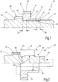
- a first embodiment of a shaft assembly is shown schematically in longitudinal section and generally designated 10.
- the shaft assembly 10 has a shaft 12, which may be a solid shaft or a hollow shaft. Furthermore, the shaft assembly 10 includes a fixed wheel assembly 14.
- the Festradan extract 14 has a first fixed wheel 16 with a first fixed gear teeth 18 on the outer circumference. Furthermore, the first fixed wheel 16 has a first axial side 20 and a second axial side 22.
- the fixed gear assembly 14 further includes a hollow shaft portion 24 extending from the first axial side 20 of the first fixed gear 16 in the axial direction.
- the axial length of the hollow shaft portion 24 is preferably at least as large as the axial length of the first fixed wheel 16, and preferably less than four times the axial length of the fixed wheel 16.
- a hollow shaft end of the hollow shaft portion 24 which is spaced from the first fixed wheel 16, with 26 denotes.
- the Festradan extract 14 is connected by means of a shaft-hub connection 30 with the shaft 12.
- the shaft-hub connection 30 has a main connection portion 32, which is preferably formed as a main press-fitting portion. Via the main connecting portion 32, the fixed wheel assembly 14 is fixed to the shaft 12 both in the circumferential direction and in the axial direction.
- the main connecting portion 32 is axially spaced from the second axial side 22 of the first fixed wheel 16, as shown at 34. Further, the main connection portion 32 is axially spaced from the hollow shaft end 26 in the axial direction, as indicated at 36.
- the distances 34, 36 are preferably at least half as large as the axial length of the fixed wheel 16.
- the main connecting portion 32 is formed so that it is not under the fixed gear teeth 18 is arranged, so that in the representation of the Fig. 1 the first distance 34 is at least as large as the axial length of the fixed wheel 16.
- a second fixed gear 40 with a second fixed-gear toothing 42 is formed on the shaft 12.
- the second fixed gear 40 is in this case formed integrally with the shaft 12.
- a bearing member 44 for example in the form of a bearing bush or in the form of a needle bearing, is arranged.
- the shaft-hub connection 30 is not to undue increases in voltage in the region of the adjacent components (that is, the second fixed wheel 40th and / or the bearing component 44) leads.
- the fixed gear assembly 14 it is possible to arrange the fixed gear assembly 14 directly adjacent to these components.
- Fig. 2 shows the realization of the main connection portion 32 by means of a main interference fit portion.
- Fig. 2 schematically shows that the fixed wheel assembly 14 has a continuous uniform inner radius 50.
- the shaft 12 has, in the area of the main press-fitting section 32, an outer radius 52 which is realized with an excess in relation to the inner radius 50.
- the shaft-hub connection 30 further includes a first sub-connection portion 54 in the form of a sub-interference fit portion.
- the shaft 12 has an outer radius 56, which is also made with excess over the inner radius 50.
- the shaft-hub connection 30 has, in the region of the second distance 36, a second auxiliary connection section 58, in which the shaft 12 has an outer radius 60, which is also preferably produced with an oversize relative to the inner diameter 50.
- the excess of the outer radius 52 of the main interference fit portion 32 is greater than the excess of the outer radii 56, 60 of the Maupresspassungsabitese 54, 58th
- Fig. 2 is also shown schematically by an arrow that the Festradan eleven 14 is pushed in the axial direction of the shaft 12 and then pressed in the region of the shaft-hub connection 30, wherein the second fixed wheel 40 may be disposed immediately adjacent to the second axial side 22 , or can serve as a stop when pressing.
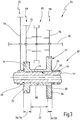
- Fig. 3 shows in schematic form a vehicle transmission 64, which is designed as a countershaft transmission in Stirnradbauweise.
- the vehicle transmission 64 has a shaft arrangement 10 ', which in terms of construction and operation of the shaft assembly 10 of the Fig. 1 and 2 equivalent.
- the same elements are therefore identified by the same reference numerals. The following section essentially explains the differences.
- the vehicle transmission 64 has a further shaft 66, which is arranged offset parallel to the shaft 12 '. Furthermore, the vehicle transmission 64 has a plurality of wheelsets, including a wheelset 68, which may be designed, for example, for a gear 3, a wheelset 70, which may be formed for example for a gear 5, and a gear set 72, for example, for a gear 1 may be formed.
- a wheelset 68 which may be designed, for example, for a gear 3
- a wheelset 70 which may be formed for example for a gear 5
- a gear set 72 for example, for a gear 1
- the wheelset 68 has a loose wheel 74 which is rotatably mounted on the further shaft 66.
- the wheel set 70 has a loose wheel 76, which is rotatably mounted on the further shaft 66.
- the wheel set 72 has a loose wheel 78, which is rotatably mounted on the further shaft 66.
- a clutch pack 80 is disposed on the further shaft 66, by means of which a neutral position can be set, and two switch positions in which either the idler gear 74 rotatably connected to the other shaft 66, or the idler gear 76th Clutch packages 80 of this type are well known.
- the clutch pack 80 may include, for example, synchronizer clutches.
- the idler gear 74 of the wheelset 68 is in rotational engagement with the first fixed gear 16.
- the idler gear 78 of the wheelset 72 is in rotary engagement with the second fixed gear 40th
- the third fixed gear 84 is disposed on the outer circumference of the hollow shaft portion 24 adjacent to the hollow shaft end 26.
- One axial side of the third fixed gear 84 is preferably axially aligned with the hollow shaft end 26.
- the fixed wheel assembly 14 ' is connected via a shaft-hub connection 30 to the shaft 12', which also has a main connection portion 32 and two auxiliary connection portions 54, 58.
- the auxiliary connection portion 54 is from the second axial side 22 of FIG first fixed wheel 16 further apart than the axial length of the first fixed wheel 16.
- the main connecting portion 32 is spaced from the hollow shaft end 26 by at least half the axial length of the third fixed wheel 84.
- the Festradan elbow 14 ' may be made in one piece from a blank.
- the Festradan eleven ' may be formed from a first Festradabrough with a first axially projecting hollow shaft section and from a second Festradabites with a second axially projecting hollow shaft section, wherein the hollow shaft section to form the hollow shaft portion 24 are fixedly connected to each other by a peripheral connection, as indicated schematically at 86.
- the peripheral connection may for example be a welded joint.
- the fixed wheel assembly 14 may also be formed by a hollow shaft portion which may be connected via two fixed-wheel connections with respective fixed wheels. In the latter case, the blanks can be made easier.
Description
Die vorliegende Erfindung betrifft eine Wellenanordnung für ein Getriebe, mit einer Welle und mit einer an der Welle mittels einer Welle-Nabe-Verbindung festgelegten Festradanordnung, die ein Festrad und einen Hohlwellenabschnitt aufweist, wobei das Festrad eine erste axiale Seite, eine zweite axiale Seite sowie eine Verzahnung aufweist, wobei der Hohlwellenabschnitt die Welle umgibt und sich von der ersten axialen Seite des Festrades erstreckt. So eine Wellenanordnung ist aus der
Ferner betrifft die vorliegende Erfindung ein Fahrzeuggetriebe mit einer Welle und wenigstens einem daran festgelegten Festrad, das zur Einrichtung einer Gangstufe des Fahrzeuggetriebes mit einem Losrad in Eingriff steht, das an einer weiteren Welle drehbar gelagert ist.Furthermore, the present invention relates to a vehicle transmission with a shaft and at least one fixed thereto fixed wheel, which is for establishing a gear stage of the vehicle transmission with a loose wheel engaged, which is rotatably mounted on another shaft.
Auf dem Gebiet der Fahrzeuggetriebe ist es bekannt, Gangstufen durch Radsätze einzurichten, die ein Losrad und ein Festrad aufweisen. Das Losrad ist hierbei mittels einer Schaltkupplung mit der zugeordneten Welle verbindbar oder hiervon trennbar, um die zugeordnete Gangstufe einzulegen oder auszulegen. Die Schaltkupplung kann eine Synchron-Schaltkupplung sein, insbesondere mit Sperrsynchronisierung.In the field of vehicle transmissions, it is known to establish gear ratios by wheelsets having a loose wheel and a fixed gear. The idler gear is in this case connectable by means of a clutch with the associated shaft or separable therefrom to insert or interpret the associated gear ratio. The clutch may be a synchronous clutch, in particular with lock synchronization.
Ein Fahrzeuggetriebe dieser Art weist in der Regel eine Mehrzahl von Gangstufen auf, die jeweils durch einen Radsatz gebildet sind. Dabei ist es auch bekannt, ein Festrad mit zwei Losrädern zu verbinden, so dass das Festrad zwei Gangstufen zugeordnet werden kann (so genannte Doppelnutzung).A vehicle transmission of this type generally has a plurality of gear stages, which are each formed by a wheel set. It is also known to connect a fixed wheel with two loose wheels, so that the fixed gear can be assigned to two gear ratios (so-called double use).
An einer Welle eines solchen Fahrzeuggetriebes können dabei Festräder und Losräder benachbart zueinander angeordnet sein.On a shaft of such a vehicle transmission while fixed wheels and idler gears can be arranged adjacent to each other.
Zur festen Verbindung eines Festrades mit einer Welle sind verschiedene Arten von Welle-Nabe-Verbindungen bekannt. Zum einen ist es bekannt, ein einzelnes Festrad mittels zylindrischem Presssitz auf einen Wellenabschnitt aufzupressen. Alternativ ist es bekannt, am Innenumfang des Festrades und am Außenumfang eines Wellenabschnittes eine Steckverzahnung auszubilden, die flankenzentriert oder kopfzentriert sein kann. Schließlich ist es bekannt, ein Festrad an einen Wellenabschnitt zu schweißen, beispielsweise mittels Reifschweißen oder Laserschweißen. Bei manchen Welle-Nabe-Verbindungen ist eine axiale Sicherung erforderlich, um das Festrad in axialer Richtung an der Welle festzulegen. Der Fügebereich (Presssitz oder Steckverzahnung) erstreckt sich hierbei in der Regel über die gesamte axiale Länge des Festrades.For fixed connection of a fixed wheel with a shaft, various types of shaft-hub connections are known. On the one hand, it is known to press a single fixed wheel by means of a cylindrical press fit on a shaft section. Alternatively, it is known to form a spline on the inner circumference of the fixed wheel and on the outer circumference of a shaft portion, which can be flank-centered or head-centered. Finally, it is known to weld a fixed wheel to a shaft section, for example by means of rake welding or laser welding. In some shaft-hub connections an axial securing is required to fix the fixed wheel in the axial direction of the shaft. The joining area (press fit or spline) extends here usually over the entire axial length of the fixed wheel.
Die Welle-Nabe-Verbindungen sind auf diesem Gebiet vorzugsweise im Wesentlichen rotationssymmetrisch ausgebildet. Nicht-rotationssymmetrische Welle-Nabe-Verbindungen, beispielsweise mittels einer Passfeder, führen in der Regel zu lokalen Spannungsüberhöhungen, so dass die beteiligten Bauteile sehr massiv ausgebildet werden müssen.The shaft-hub connections are formed in this area preferably substantially rotationally symmetrical. Non-rotationally symmetric shaft-hub connections, for example by means of a feather key, usually lead to local voltage peaks, so that the components involved must be made very solid.
Bei dem Aufpressen mittels zylindrischem Presssitz oder bei einer Steckverzahnung unter der Außenverzahnung des Festrades werden aufgrund hoher Pressüberdeckung häufig hohe Spannungen in die Außenverzahnung eingeleitet. Hierdurch kann die Lebensdauer der Wellenanordnung verringert werden. Zudem können angrenzende Verzahnungen, Lagerlaufbahnen oder Lager, die eine hohe Genauigkeit aufweisen müssen, verformt und/oder belastet werden.When pressing by means of cylindrical interference fit or with a spline under the outer teeth of the fixed wheel high voltages are often introduced into the external teeth due to high press coverage. As a result, the life of the shaft assembly can be reduced. In addition, adjacent gears, bearing tracks or bearings, which must have high accuracy, deformed and / or loaded.
Das Fertigen einer Steckverzahnung ist in der Regel deutlich kostenintensiver als das Fertigen einer zylindrischen Oberfläche mit ausreichender Güte zum Herstellen einer Presssitzverbindung.The preparation of a spline is usually much more expensive than the manufacture of a cylindrical surface with sufficient quality for making a press-fit connection.
Die Möglichkeit der Ausführung einer Welle-Nabe-Verbindung mittels Schweißen erfordert einen deutlich höheren Arbeits- und Kostenaufwand als das Fertigen einer zylindrischen Oberfläche mit ausreichender Güte und folgendem Aufpressvorgang in der Montage. Denn beim Schweißen sind gegebenenfalls zusätzliche Vorkehrungen bzw. Arbeitsschritte vorzusehen, beispielsweise das Glühen eines Rohlings, das Reinigen und Vorwärmen vor dem Schweißen, gegebenenfalls das Abdrehen einer Hartschicht, etc.The possibility of performing a shaft-hub connection by welding requires a significantly higher labor and cost than the production of a cylindrical surface with sufficient quality and subsequent Aufpressvorgang in the assembly. Because when welding additional precautions or steps are optionally provided, for example, the annealing of a blank, the cleaning and preheating before welding, optionally the twisting of a hard layer, etc.
Vor diesem Hintergrund ist es eine Aufgabe der Erfindung, eine Wellenanordnung für ein Getriebe sowie ein hiermit ausgestattetes Fahrzeuggetriebe anzugeben, die ein möglichst robustes Design bei möglichst geringen Auswirkungen auf angrenzende Bauteile besitzt, wobei die Wellenanordnung kostengünstig zu fertigen ist.Against this background, it is an object of the invention to provide a shaft assembly for a transmission and a vehicle equipped therewith vehicle transmission, which has a robust design as possible with minimal impact on adjacent components, the shaft assembly is inexpensive to manufacture.
Die obige Aufgabe wird bei der eingangs genannten Wellenanordnung mit den Merkmalen des Anspruchs 1 gelöst.The above object is achieved in the shaft assembly mentioned above with the features of claim 1.
Unter einem Hauptverbindungsabschnitt wird vorliegend jener Abschnitt der Welle-Nabe-Verbindung verstanden, über den ein Drehmoment zwischen Welle und Festrad hauptsächlich übertragen wird. Durch die axiale Beabstandung des Hauptverbindungsabschnittes von der zweiten axialen Seite des Festrades und/oder von dem Hohlwellenende wird erreicht, dass dieser Hauptverbindungsabschnitt einen geringeren Einfluss auf benachbarte Bauteile hat. Hierdurch ist es möglich, auch solche Bauteile direkt benachbart zu der Festradanordnung an der Welle zu montieren, die mit hoher Präzision zu fertigen sind. Ferner hat die Maßnahme den Vorteil, dass gegebenenfalls auch der Einfluss der Welle-Nabe-Verbindung auf die Verzahnung des Festrades der Festradanordnung geringer ist, so dass die Lebensdauer erhöht werden kann.In the present case, a main connection section is understood to be that section of the shaft-hub connection via which a torque between shaft and fixed wheel is mainly transmitted. The axial spacing of the main connecting portion from the second axial side of the fixed wheel and / or from the hollow shaft end ensures that this main connecting portion has a smaller influence on adjacent components. This makes it possible to mount such components directly adjacent to the Festradanordnung on the shaft, which are to be manufactured with high precision. Furthermore, the measure has the advantage that, where appropriate, the influence of the shaft-hub connection on the toothing of the fixed wheel of the fixed gear arrangement is lower, so that the service life can be increased.
Durch den axial von dem Festrad vorstehenden Hohlwellenabschnitt ergibt sich zudem eine relativ lange Einfädellänge zur Zentrierung der Festradanordnung bei der Montage an der Welle.By axially projecting from the fixed wheel hollow shaft portion also results in a relatively long Einfädellänge for centering the fixed gear assembly during assembly to the shaft.
Insgesamt wird ein robustes Design bei möglichst geringen Auswirkungen auf angrenzende Bauteile (Lager, Verzahnungen etc.) geschaffen. Zudem kann der Hauptverbindungsabschnitt gegebenenfalls kostengünstig hergestellt werden, und zwar bei geringem Arbeitsaufwand. Der Hauptverbindungsabschnitt kann auf einer an sich bekannten Technologie basieren, die möglichst geringe Risiken bei der Fertigung, bei der Montage und im Betrieb beinhaltet.Overall, a robust design with the lowest possible impact on adjacent components (bearings, gears, etc.) is created. In addition, if necessary, the main connecting portion can be manufactured inexpensively, with a minimum of labor. The main connection section may be based on a per se known technology, which involves the lowest possible risks during production, assembly and operation.
Schließlich ist es gegebenenfalls möglich, relativ zu dem Durchmesser des Festrades einen relativ großen Fügedurchmesser des Hauptverbindungsabschnittes zu realisieren, so dass eine Festlegung der Festradanordnung an der Welle mit hoher Sicherheit realisiert werden kann. Der Hauptverbindungsabschnitt legt die Festradanordnung hierbei an der Welle in Umfangsrichtung fest, und vorzugsweise auch in axialer Richtung. Besonders bevorzugt ist es, wenn der Hauptverbindungsabschnitt dazu eingerichtet ist, Axial-, Radial- und Umfangskräfte übertragen zu können.Finally, it may be possible to realize a relatively large joint diameter of the main connecting portion relative to the diameter of the fixed wheel, so that a fixing of the fixed wheel arrangement to the shaft can be realized with high safety. The main connecting portion sets the fixed wheel assembly in this case fixed to the shaft in the circumferential direction, and preferably also in the axial direction. It is particularly preferred if the main connection section is adapted to be able to transmit axial, radial and circumferential forces.
Die Aufgabe wird somit vollkommen gelöst.The task is thus completely solved.
Gemäß einer besonders bevorzugten Ausführungsform weist der Hohlwellenabschnitt ein von dem Festrad entferntes Hohlwellenende auf, wobei das Hohlwellenende am Außenumfang mit einem weiteren Festrad fest verbunden ist.According to a particularly preferred embodiment, the hollow shaft section has a hollow shaft end remote from the fixed wheel, wherein the hollow shaft end is fixedly connected to a further fixed wheel on the outer circumference.
Hierbei beinhaltet die Festradanordnung folglich zwei Festräder, die über den Hohlwellenabschnitt miteinander verbunden sind.In this case, the fixed wheel assembly thus includes two fixed wheels, which are interconnected via the hollow shaft portion.
Der Hauptverbindungsabschnitt liegt dabei in axialer Richtung vorzugsweise zwischen den zwei Festrädern.The main connecting portion is preferably in the axial direction between the two fixed wheels.
Sofern eines der Festräder einen im Vergleich zum Welle-Nabe-Verbindungsdurchmesser relativ kleinen Außendurchmesser aufweist, ist der Hauptverbindungsabschnitt vorzugsweise um wenigstens die Hälfte der axialen Länge und insbesondere um wenigstens die gesamte axiale Länge des Festrades von der zweiten axialen Seite des Festrades und/oder von dem Hohlwellenende beabstandet. Sofern ein Festrad einen im Vergleich zum Welle-Nabe-Verbindungsdurchmesser relativ großen Durchmesser aufweist, kann sich der Hauptverbindungsabschnitt auch teilweise in axialer Richtung mit dem Festrad überdecken. Auch in diesem Fall ist es jedoch bevorzugt, wenn der Hauptverbindungsabschnitt von dem jeweiligen Ende der Festradanordnung um wenigstens die Hälfte der axialen Länge des Festrades beabstandet ist.If one of the fixed wheels has a relatively small outer diameter compared to the shaft-hub connecting diameter, the main connecting portion is preferably at least half the axial length and in particular at least the entire axial length of the fixed wheel from the second axial side of the fixed wheel and / or the hollow shaft end spaced. If a fixed gear has a relatively large diameter compared to the shaft-hub connection diameter, the main connection section can also partially overlap in the axial direction with the fixed wheel. However, in this case as well, it is preferable that the main connection portion is spaced from the respective end of the fixed gear assembly by at least half the axial length of the fixed gear.
Wie oben erwähnt, ist es generell möglich, für den Hauptverbindungsabschnitt eine der üblichen Welle-Nabe-Verbindungen zu verwenden.As mentioned above, it is generally possible to use one of the usual shaft-hub connections for the main connection section.
Von besonderem Vorzug ist es jedoch, wenn der Hauptverbindungsabschnitt durch einen Haupt-Presspassungsabschnitt gebildet ist.However, it is particularly preferable if the main connection portion is formed by a main press-fitting portion.
Eine derartige Verbindung mittels zylindrischem Presssitz ist kostengünstig herzustellen. Durch die Maßnahme, den Haupt-Presspassungsabschnitt von wenigstens einem axialen Ende der Festradanordnung zu beabstanden, kann der Haupt-Presspassungsabschnitt zudem mit einem hohen Übermaß realisiert werden, so dass hohe Kräfte übertragbar sind, ohne dass dies zu unzulässigen Verformungen benachbart zu der Festradanordnung führt (an der Welle oder an einem mit der Welle verbundenen Bauteil).Such a connection by means of cylindrical interference fit is inexpensive to manufacture. In addition, by the measure of spacing the main press-fit portion from at least one axial end of the fixed gear assembly, the main press-fit portion can be realized with a high degree of excess so that high forces are transferable without resulting in undue deformations adjacent the fixed-wheel assembly (FIG. on the shaft or on a component connected to the shaft).
Generell ist es möglich, den Bereich zwischen dem Haupt-Presspassungsabschnitt und der zweiten axialen Seite des Festrades bzw. dem Hohlwellenende als Spielpassung auszuführen, so dass diese Bereiche im Wesentlichen kein Drehmoment übertragen können.In general, it is possible to make the area between the main press-fit portion and the second axial side of the fixed wheel or the hollow shaft end as a clearance fit, so that these areas can transmit substantially no torque.
Bevorzugt ist es jedoch insgesamt, wenn die Welle-Nabe-Verbindung wenigstens einen Nebenverbindungsabschnitt aufweist, der in axialer Richtung zwischen dem Hauptverbindungsabschnitt und einem Ende der Festradanordnung ausgebildet ist, wobei der Hauptverbindungsabschnitt eine höhere Drehmomentübertragungsfähigkeit aufweist als der Nebenverbindungsabschnitt.However, it is preferable as a whole when the shaft-hub connection has at least one sub connection portion formed in the axial direction between the main connection portion and one end of the fixed gear assembly, the main connection portion having a higher torque transmission capability than the sub connection portion.
Bei dieser Ausführungsform kann auch der Nebenverbindungsabschnitt ein Drehmoment übertragen, jedoch ein geringeres Drehmoment als der Hauptverbindungsabschnitt.Also, in this embodiment, the sub connection portion can transmit a torque but a lower torque than the main connection portion.
Dabei ist es von besonderem Vorteil, wenn der Hauptverbindungsabschnitt durch einen Haupt-Presspassungsabschnitt gebildet ist, wobei der Nebenverbindungsabschnitt durch einen Neben-Presspassungsabschnitt gebildet ist und wobei der Haupt-Presspassungsabschnitt ein größeres Übermaß aufweist als der Neben-Presspassungsabschnitt.In this case, it is particularly advantageous if the main connection section is formed by a main press-fit section, wherein the secondary connection section is formed by a secondary press-fit section and wherein the main press-fit section has a greater oversize than the secondary press-fit section.
Bei dieser Variante haben sowohl der Haupt- als auch der Neben-Presspassungsabschnitt jeweils ein Übermaß, sind also als Presspassung ausgebildet und können folglich Drehmoment übertragen. Aufgrund der Maßnahme, den Haupt-Presspassungsabschnitt mit einem größeren Übermaß zu realisieren, kann der Haupt-Presspassungsabschnitt hierbei eine höhere Drehmomentübertragungsfähigkeit aufweisen als der Neben-Presspassungsabschnitt.In this variant, both the main and the Nebenpresspassungsabschnitt each have an excess, so are formed as a press fit and can therefore transmit torque. Due to the measure, the main press-fitting section With a larger excess, the main press-fit portion may have higher torque-transmitting capability than the sub-press-fit portion.
Ein Übergang zwischen dem Haupt-Presspassungsabschnitt und dem Neben-Presspassungsabschnitt kann dabei stufig ausgebildet sein. Der Übergang kann jedoch auch kontinuierlich ausgebildet sein. In letzterem Fall können unterschiedliche Presspassungsdurchmesser über eine stetige Verbindung ineinander übergehen.A transition between the main press-fitting portion and the sub-press-fitting portion may be formed in stages. However, the transition can also be formed continuously. In the latter case, different press-fitting diameters can merge into one another via a continuous connection.
Die unterschiedlichen Übermaße können dabei am Innenumfang der Festradanordnung ausgebildet sein. Von besonderem Vorzug ist es jedoch, wenn die unterschiedlichen Übermaße am Außenumfang eines Abschnittes der Welle ausgebildet sind, auf den die Festradanordnung aufzupressen ist.The different excess dimensions can be formed on the inner circumference of the Festradanordnung. It is particularly preferred, however, if the different excess dimensions are formed on the outer circumference of a portion of the shaft on which the Festradanordnung is to be pressed.
In einer insgesamt bevorzugten Ausführungsform ist an der Welle eine Festrad-Verzahnung ausgebildet, wobei die Festradanordnung axial direkt an die Festrad-Verzahnung angrenzt.In an overall preferred embodiment, a fixed gear toothing is formed on the shaft, wherein the fixed wheel assembly axially adjacent to the fixed gear teeth.
Die Festrad-Verzahnung der Welle kann einstückig mit der Welle ausgebildet sein.The fixed gear teeth of the shaft may be formed integrally with the shaft.
Gemäß einer weiteren bevorzugten Ausführungsform ist ein Lagerbauteil, wie eine Lagerbuchse oder ein Nadellager oder dergleichen, axial direkt an der Festradanordnung angrenzend angeordnet.According to a further preferred embodiment, a bearing component, such as a bearing bush or a needle bearing or the like, axially disposed directly adjacent to the Festradanordnung.
Die direkt angrenzende Anordnung einer Festrad-Verzahnung und/oder eines Lagerbauteils an der Festradanordnung wird insbesondere auch dadurch ermöglicht, dass der Hauptverbindungsabschnitt axial von den Enden der Festradanordnung beabstandet ist, so dass keine unzulässigen Spannungen durch die Welle-Nabe-Verbindung auf direkt angrenzende Bauteile wie die Festrad-Verzahnung oder das Lagerbauteil ausgeübt werden.The directly adjacent arrangement of a fixed-gear toothing and / or a bearing component on the Festradanordnung is also made possible in that the main connecting portion is axially spaced from the ends of the Festradanordnung, so that no undue stress by the shaft-hub connection on directly adjacent components how the fixed gear teeth or the bearing component are exercised.
Die Festradanordnung kann insgesamt aus einem Rohling einstückig hergestellt sein, beispielsweise durch spanende Bearbeitungsverfahren.The fixed wheel assembly can be made in one piece from a blank, for example, by machining processes.
Gemäß einer bevorzugten Ausführungsform ist die Festradanordnung aus einem ersten Festradabschnitt mit einem ersten axial vorstehenden Hohlwellenteilabschnitt und aus einem zweiten Festradabschnitt mit einem zweiten axial vorstehenden Hohlwellenteilabschnitt hergestellt, wobei der erste und der zweite Hohlwellenteilabschnitt durch eine Umfangsverbindung fest miteinander verbunden sind.According to a preferred embodiment, the fixed gear assembly is made of a first Festradabschnitt with a first axially projecting hollow shaft section and a second Festradabschnitt with a second axially projecting hollow shaft section, wherein the first and the second hollow shaft section are connected by a peripheral connection firmly together.
Die Umfangsverbindung kann insbesondere eine stoffschlüssige Verbindung sein, die beispielsweise durch Reifschweißen gebildet sein kann.The peripheral connection may in particular be a cohesive connection, which may be formed for example by rake welding.
In einer weiteren alternativen Ausführungsform ist die Festradanordnung aus einem ersten Festradabschnitt mit einem axial vorstehenden Hohlwellenabschnitt und aus einem Festrad gebildet, das mit einem Außenumfangsabschnitt des Hohlwellenabschnittes über eine Festradverbindung fest verbunden ist. Die Festradverbindung kann beispielsweise eine Schweißverbindung sein.In a further alternative embodiment, the fixed gear assembly is formed of a first fixed gear portion having an axially projecting hollow shaft portion and a fixed gear which is fixedly connected to an outer peripheral portion of the hollow shaft portion via a fixed gear. The fixed gear can be, for example, a welded joint.
Generell ist es jedoch auch möglich, einen Hohlwellenabschnitt bereitzustellen, der zwei axial beabstandete Außenumfangsabschnitte aufweist, an die jeweils ein einzelnes Festrad mittels einer solchen Festradverbindung festgelegt ist.In general, however, it is also possible to provide a hollow shaft portion having two axially spaced outer peripheral portions, to each of which a single fixed wheel is fixed by means of such a fixed gear.
Insgesamt wird mit der vorliegenden Erfindung wenigstens einer der folgenden Vorteile erzielt.Overall, at least one of the following advantages is achieved with the present invention.
Zum einen ist es innerhalb eines Haupt-Presspassungsabschnittes möglich, ein Pressen mit einer höheren Überdeckung bzw. einem höheren Übermaß zu realisieren, als es radial unter einer Festradaußenverzahnung realisierbar wäre.On the one hand, it is possible within a main press-fitting section to realize a pressing with a higher overlap or a higher excess than would be realized radially under a fixed external gear.
Das Übermaß eines Haupt-Presspassungsabschnittes ist vorzugsweise wenigstens 25 %, und insbesondere wenigstens 40 % größer als das Übermaß eines Neben-Presspassungsabschnittes.The excess of a main interference fit portion is preferably at least 25%, and more preferably at least 40% greater than the excess interference fit portion.
Durch den relativ langen Einführdurchmesser des Hohlwellenabschnittes ergibt sich beim Aufpressvorgang eine gute Zentrierung. Bei gegebenen Abmessungen kann die Außenverzahnung des Festrades mehr Drehmoment übertragen bzw. ist höher belastbar.Due to the relatively long insertion diameter of the hollow shaft section results in the pressing a good centering. For given dimensions, the external teeth of the fixed wheel can transmit more torque or is more resilient.
Durch den Haupt-Presspassungsabschnitt in der axialen Mitte der Festradanordnung kann ein Nadellagersitz direkt an der Festradanordnung angrenzen.The main press-fit portion in the axial center of the fixed gear assembly allows a needle bearing seat to abut directly against the fixed wheel assembly.
Durch Fertigung bzw. Hartbearbeitung eines Bauteils (Festradanordnung) entsteht eine geringe Breitentoleranz, so dass sich Vorteile hinsichtlich der Toleranzrechnung ergeben.By manufacturing or hard machining of a component (Festradanordnung) creates a low width tolerance, so that there are advantages in terms of tolerance calculation.
Bei Realisierung des Hauptverbindungsabschnittes durch einen Haupt-Presspassungsabschnitt ist eine axiale Sicherung nicht nötig, wie sie beim Fügen mittels Steckverzahnungen vorzusehen ist.When realizing the main connection section through a main press-fit section, an axial securing is not necessary, as is to be provided during joining by means of splines.
Es versteht sich, dass die vorstehend genannten und die nachstehend noch zu erläuternden Merkmale nicht nur in der jeweils angegebenen Kombination, sondern auch in anderen Kombinationen oder in Alleinstellung verwendbar sind, ohne den Rahmen der vorliegenden Erfindung zu verlassen.It is understood that the features mentioned above and those yet to be explained below can be used not only in the particular combination given, but also in other combinations or in isolation, without departing from the scope of the present invention.
Ausführungsbeispiele der Erfindung sind in der Zeichnung dargestellt und werden in der nachfolgenden Beschreibung näher erläutert. Es zeigen:
- Fig. 1
- eine schematische Längsschnittansicht durch eine erste Ausführungsform einer erfindungsgemäßen Wellenanordnung;
- Fig. 2
- die Wellenanordnung der
Fig. 1 vor der Montage; und - Fig. 3
- eine schematische Längsschnittansicht durch ein Kraftfahrzeuggetriebe mit einer erfindungsgemäßen Wellenanordnung.
- Fig. 1
- a schematic longitudinal sectional view through a first embodiment of a shaft assembly according to the invention;
- Fig. 2
- the shaft arrangement of
Fig. 1 before assembly; and - Fig. 3
- a schematic longitudinal sectional view through a motor vehicle transmission with a shaft assembly according to the invention.
In
Die Wellenanordnung 10 weist eine Welle 12 auf, bei der es sich um eine Vollwelle oder um eine Hohlwelle handeln kann. Ferner beinhaltet die Wellenanordnung 10 eine Festradanordnung 14.The
Die Festradanordnung 14 weist ein erstes Festrad 16 mit einer ersten Festrad-Verzahnung 18 am Außenumfang auf. Ferner weist das erste Festrad 16 eine erste axiale Seite 20 und eine zweite axiale Seite 22 auf.The
Die Festradanordnung 14 beinhaltet ferner einen Hohlwellenabschnitt 24, der sich von der ersten axialen Seite 20 des ersten Festrades 16 in axialer Richtung erstreckt. Die axiale Länge des Hohlwellenabschnittes 24 ist vorzugsweise wenigstens so groß wie die axiale Länge des ersten Festrades 16, und vorzugsweise kleiner als das Vierfache der axialen Länge des Festrades 16. Ein Hohlwellenende des Hohlwellenabschnittes 24, das von dem ersten Festrad 16 beabstandet ist, ist mit 26 bezeichnet.The fixed
Die Festradanordnung 14 ist mittels einer Welle-Nabe-Verbindung 30 mit der Welle 12 verbunden. Die Welle-Nabe-Verbindung 30 weist einen Hauptverbindungsabschnitt 32 auf, der vorzugsweise als Haupt-Presspassungsabschnitt ausgebildet ist. Über den Hauptverbindungsabschnitt 32 wird die Festradanordnung 14 sowohl in Umfangsrichtung als auch in axialer Richtung an der Welle 12 festgelegt.The
Der Hauptverbindungsabschnitt 32 ist in axialer Richtung von der zweiten axialen Seite 22 des ersten Festrades 16 beabstandet, wie es bei 34 gezeigt ist. Ferner ist der Hauptverbindungsabschnitt 32 in axialer Richtung von dem Hohlwellenende 26 axial beabstandet, wie es bei 36 angedeutet ist.The main connecting
Die Abstände 34, 36 sind vorzugsweise mindestens halb so groß wie die axiale Länge des Festrades 16. In einer besonders bevorzugten Ausführungsform ist der Hauptverbindungsabschnitt 32 so ausgebildet, dass er nicht unter der Festrad-Verzahnung 18 angeordnet ist, so dass bei der Darstellung der
Axial direkt benachbart zu dem ersten Festrad 16 ist an der Welle 12 ein zweites Festrad 40 mit einer zweiten Festrad-Verzahnung 42 ausgebildet. Das zweite Festrad 40 ist hierbei einstückig mit der Welle 12 gebildet. Unmittelbar benachbart zu dem Hohlwellenende 26 ist ein Lagerbauteil 44, beispielsweise in Form einer Lagerbuchse oder in Form eines Nadellagers, angeordnet.Axially directly adjacent to the first fixed
Durch die Abstände 34, 36 des Hauptverbindungsabschnittes 32 von der zweiten axialen Seite 22 und/oder von dem Hohlwellenende 26 kann erreicht werden, dass die Welle-Nabe-Verbindung 30 nicht zu unzulässigen Spannungserhöhungen im Bereich der benachbarten Komponenten (das heißt des zweiten Festrades 40 und/oder des Lagerbauteils 44) führt. Demzufolge ist es möglich, die Festradanordnung 14 direkt benachbart zu diesen Komponenten anzuordnen.By the
In dem Bereich des ersten Abstandes beinhaltet die Welle-Nabe-Verbindung 30 ferner einen ersten Nebenverbindungsabschnitt 54 in Form eines Neben-Presspassungsabschnittes. In diesem Bereich weist die Welle 12 einen Außenradius 56 auf, der ebenfalls mit Übermaß gegenüber dem Innenradius 50 hergestellt ist. In entsprechender Weise weist die Welle-Nabe-Verbindung 30 im Bereich des zweiten Abstandes 36 einen zweiten Nebenverbindungsabschnitt 58 auf, in dem die Welle 12 einen Außenradius 60 aufweist, der vorzugsweise ebenfalls mit Übermaß gegenüber dem Innendurchmesser 50 hergestellt ist.In the region of the first distance, the shaft-
Das Übermaß des Außenradius 52 des Haupt-Presspassungsabschnittes 32 ist dabei größer als das Übermaß der Außenradien 56, 60 der Neben-Presspassungsabschnitte 54, 58.The excess of the
In
Nach dem Aufpressen der Festradanordnung 14 auf die Welle 12 können in der gleichen axialen Richtung weitere Komponenten auf die Welle 12 aufgeschoben bzw. aufgepresst werden, beispielsweise das Lagerbauteil 44.After pressing the
Das Fahrzeuggetriebe 64 weist eine weitere Welle 66 auf, die parallel versetzt zu der Welle 12' angeordnet ist. Ferner weist das Fahrzeuggetriebe 64 eine Mehrzahl von Radsätzen auf, einschließlich eines Radsatzes 68, der beispielsweise für eine Gangstufe 3 ausgelegt sein kann, eines Radsatzes 70, der beispielsweise für eine Gangstufe 5 ausgebildet sein kann, und eines Radsatzes 72, der beispielsweise für eine Gangstufe 1 ausgebildet sein kann.The
Der Radsatz 68 weist ein Losrad 74 auf, das drehbar an der weiteren Welle 66 gelagert ist. In entsprechender Weise weist der Radsatz 70 ein Losrad 76 auf, das drehbar an der weiteren Welle 66 gelagert ist. Schließlich weist der Radsatz 72 ein Losrad 78 auf, das drehbar an der weiteren Welle 66 gelagert ist.The
Zwischen den Losrädern 74, 76 ist ein Schaltkupplungspaket 80 an der weiteren Welle 66 angeordnet, mittels dessen eine Neutralstellung eingerichtet werden kann, sowie zwei Schaltstellungen, bei denen entweder das Losrad 74 drehfest mit der weiteren Welle 66 verbunden ist, oder das Losrad 76. Schaltkupplungspakete 80 dieser Art sind allgemein bekannt. Das Schaltkupplungspaket 80 kann beispielsweise Synchron-Sperrkupplungen aufweisen.Between the idler gears 74, 76, a
Das Losrad 74 des Radsatzes 68 steht in Dreheingriff mit dem ersten Festrad 16. Das Losrad 78 des Radsatzes 72 steht in Dreheingriff mit dem zweiten Festrad 40.The
Vorliegend weist die Festradanordnung 14' der Wellenanordnung 10' ein weiteres, drittes Festrad 84 auf, das in Dreheingriff steht mit dem Losrad 76 des Radsatzes 70.In the present case, the fixed gear assembly 14 'of the shaft assembly 10' on another, third fixed
Das dritte Festrad 84 ist am Außenumfang des Hohlwellenabschnittes 24 angeordnet, und zwar benachbart zu dem Hohlwellenende 26. Eine axiale Seite des dritten Festrades 84 ist vorzugsweise axial mit dem Hohlwellenende 26 ausgerichtet.The third
In
Die Festradanordnung 14' kann einstückig aus einem Rohling hergestellt sein.The Festradanordnung 14 'may be made in one piece from a blank.
Alternativ kann die Festradanordnung 14' gebildet sein aus einem ersten Festradabschnitt mit einem ersten axial vorstehenden Hohlwellenteilabschnitt sowie aus einem zweiten Festradabschnitt mit einem zweiten axial vorstehenden Hohlwellenteilabschnitt, wobei die Hohlwellenteilabschnitte zur Bildung des Hohlwellenabschnittes 24 durch eine Umfangsverbindung fest miteinander verbunden sind, wie es schematisch bei 86 angedeutet ist. Die Umfangsverbindung kann beispielsweise eine Schweißverbindung sein.Alternatively, the Festradanordnung 14 'may be formed from a first Festradabschnitt with a first axially projecting hollow shaft section and from a second Festradabschnitt with a second axially projecting hollow shaft section, wherein the hollow shaft section to form the
Alternativ ist es möglich, die Festradanordnung zu bilden aus einem ersten Festradabschnitt mit einem axial vorstehenden Hohlwellenabschnitt und aus einem weiteren Festrad, das mit einem Außenumfangsabschnitt des Hohlwellenabschnittes über eine Festradverbindung verbunden ist, wie es schematisch bei 88 in
Hieraus versteht sich, dass die Festradanordnung 14 auch gebildet sein kann durch einen Hohlwellenabschnitt, der über zwei Festradverbindungen mit jeweiligen Festrädern verbunden sein kann. Im letzteren Fall können die Rohteile einfacher hergestellt werden.It is understood that the fixed
Claims (10)
- Shaft arrangement (10) for a transmission (64), having a shaft (12) and having a fixed gear arrangement (14), which is fixed on the shaft (12) by means of a shaft/hub joint (30) and has a fixed gear (16) and a hollow shaft section (24), wherein the fixed gear (16) has a first axial side (20), a second axial side (22) and a tooth system (18), wherein the hollow shaft section (24) surrounds the shaft (12) and extends from the first axial side (20) of the fixed gear (16), wherein the hollow shaft section (24) has a hollow shaft end (26) remote from the fixed gear (16), and wherein the shaft/hub joint (30) has a main joint section (32), which is formed by a main press fit section (32) and which is spaced apart in the axial direction from the second axial side (22) of the fixed gear (16),
characterized in that
the main joint section (32) is spaced apart from the hollow shaft end (26). - Shaft arrangement according to Claim 1, characterized in that the hollow shaft section (24) has a hollow shaft end (26) remote from the fixed gear (16), wherein the hollow shaft end (26) is securely connected at the outer periphery to a further fixed gear (84).
- Shaft arrangement according to one of Claims 1 or 2, characterized in that the shaft/hub joint (30) has at least one secondary joint section (54, 58), wherein the main joint section (32) has a higher torque transmission capacity than the secondary joint section (54, 58).
- Shaft arrangement according to Claim 3, characterized in that the main joint section (32) is formed by a main press fit section (32), wherein the secondary joint section (54, 58) is formed by a secondary press fit section (54, 58), and wherein the main press fit section (32) has a greater negative allowance than the secondary press fit section (54, 58).
- Shaft arrangement according to one of Claims 1-4, characterized in that a fixed gear tooth system (42) is formed on the shaft (12), wherein the fixed gear arrangement (14) directly adjoins the fixed gear tooth system (42) axially.
- Shaft arrangement according to one of Claims 1-6, characterized in that a bearing component (44) directly adjoins the fixed gear arrangement (14) axially.
- Shaft arrangement according to one of Claims 1-6, characterized in that the fixed gear arrangement (14) is produced integrally from a blank.
- Shaft arrangement according to one of Claims 1-6, characterized in that the fixed gear arrangement (14) is produced from a first fixed gear section having a first axially projecting hollow shaft subsection and from a second fixed gear section having a second axially projecting hollow shaft subsection, wherein the first and second hollow shaft subsections are securely connected to one another by a peripheral joint (86).
- Shaft arrangement according to one of Claims 1-6, characterized in that the fixed gear arrangement (14) is formed from a first fixed gear section having an axially projecting hollow shaft section (24) and from a fixed gear (16) which is securely connected to an outer periphery section of the hollow shaft section (24) by means of a fixed gear joint (88).
- Vehicle transmission (64) having a shaft (12) and having at least one fixed gear (16) fixed thereon, which, to set up a gear stage of the vehicle transmission (64), is in engagement with a free gear (74), which is rotatably mounted on a further shaft (66), wherein the shaft (12) and the fixed gear (16) are formed by a shaft arrangement (10) according to one of Claims 1 to 9.
Applications Claiming Priority (1)
| Application Number | Priority Date | Filing Date | Title |
|---|---|---|---|
| DE102013105915.5A DE102013105915A1 (en) | 2013-06-07 | 2013-06-07 | Shaft assembly for a transmission |
Publications (2)
| Publication Number | Publication Date |
|---|---|
| EP2811193A1 EP2811193A1 (en) | 2014-12-10 |
| EP2811193B1 true EP2811193B1 (en) | 2016-12-28 |
Family
ID=50774678
Family Applications (1)
| Application Number | Title | Priority Date | Filing Date |
|---|---|---|---|
| EP14169515.5A Active EP2811193B1 (en) | 2013-06-07 | 2014-05-22 | Shaft assembly for a transmission |
Country Status (4)
| Country | Link |
|---|---|
| EP (1) | EP2811193B1 (en) |
| CN (1) | CN104235322B (en) |
| DE (1) | DE102013105915A1 (en) |
| ES (1) | ES2620493T3 (en) |
Families Citing this family (3)
| Publication number | Priority date | Publication date | Assignee | Title |
|---|---|---|---|---|
| JP6706510B2 (en) * | 2016-02-19 | 2020-06-10 | ナブテスコ株式会社 | Drive device for driving a power generator |
| DE102017203773A1 (en) * | 2017-03-08 | 2018-09-13 | Bayerische Motoren Werke Aktiengesellschaft | Shaft-hub connection, as well as powertrain with such a shaft-hub connection |
| CN114962596A (en) * | 2022-07-27 | 2022-08-30 | 四川丹齿精工科技有限公司 | Gear power transmission structure with high assembly probability |
Family Cites Families (7)
| Publication number | Priority date | Publication date | Assignee | Title |
|---|---|---|---|---|
| JPS58113659A (en) * | 1981-12-26 | 1983-07-06 | Toyota Motor Corp | Fixing structure for change gear and shaft in speed change gear for automobile |
| SE515468C2 (en) * | 1999-12-23 | 2001-08-13 | Volvo Lastvagnar Ab | Gear wheels intended to be connected to a shaft by means of a press fit and a shaft bearing a press-fit gear |
| DE10003923A1 (en) * | 2000-01-29 | 2001-08-02 | Zahnradfabrik Friedrichshafen | Method of connecting a hub to a shaft |
| JP2002227866A (en) * | 2001-01-31 | 2002-08-14 | Isuzu Motors Ltd | Press fit method and press fit structure |
| US8662785B2 (en) * | 2006-11-04 | 2014-03-04 | Zf Friedrichshafen Ag | Shaft-gear connection |
| DE102006052104A1 (en) * | 2006-11-04 | 2008-05-08 | Zf Friedrichshafen Ag | Shaft-gear connection |
| DE102010023161A1 (en) * | 2010-06-09 | 2011-01-13 | Daimler Ag | Transmission gear assembly for motor vehicle, has gear wheel firmly connected within shaft section by tight fit between borehole of flank and another flank of another gear wheel, where two gear wheels are provided with hubs |
-
2013
- 2013-06-07 DE DE102013105915.5A patent/DE102013105915A1/en not_active Withdrawn
-
2014
- 2014-05-22 EP EP14169515.5A patent/EP2811193B1/en active Active
- 2014-05-22 ES ES14169515.5T patent/ES2620493T3/en active Active
- 2014-06-06 CN CN201410250537.3A patent/CN104235322B/en active Active
Non-Patent Citations (1)
| Title |
|---|
| None * |
Also Published As
| Publication number | Publication date |
|---|---|
| DE102013105915A1 (en) | 2014-12-11 |
| ES2620493T3 (en) | 2017-06-28 |
| CN104235322A (en) | 2014-12-24 |
| EP2811193A1 (en) | 2014-12-10 |
| CN104235322B (en) | 2017-01-04 |
Similar Documents
| Publication | Publication Date | Title |
|---|---|---|
| DE102019127242A1 (en) | Gearbox and arrangement of a gearbox and an electric machine | |
| EP2811193B1 (en) | Shaft assembly for a transmission | |
| DE102019125397B4 (en) | Transmission and motor vehicle with transmission | |
| DE3514578A1 (en) | DIFFERENTIAL GEARBOX | |
| EP2572117A1 (en) | Drive assembly on a double-clutch transmission for motor vehicles | |
| DE102014223505A1 (en) | Shaft-hub connection of a double gear on a gear shaft | |
| EP3882478B1 (en) | Drive train with a yieldable coupling between a motor shaft and an input shaft of a shift gearbox | |
| DE102008049978A1 (en) | Shifting unit for manual gearbox of motor vehicle, has tooth intermediate spaces rotationally coupled or decoupled with teeth of internal gear of sliding sleeve, and stops arranged on clutch bodies to limit axial displaceability of sleeve | |
| WO2020182399A1 (en) | Differential gearbox | |
| DE2848288A1 (en) | SYNCHRONIZATION DEVICE FOR A VEHICLE TRANSMISSION | |
| DE102019118187A1 (en) | Differential gear | |
| EP3699442B1 (en) | Shaft | |
| EP3482482B1 (en) | Electric motor assembly and method for assembling an electric motor assembly | |
| DE102019129236A1 (en) | Planet carrier constructed as a modular system | |
| EP1146243B1 (en) | Synchronizer assembly for shift clutch | |
| DE102008063013B3 (en) | Differential unit for use in axle drive of motor vehicle for torque distribution, has housing parts provided with flange sections that comprise multiple recesses, and ring wheel attached radially outside recesses at one of housing parts | |
| DE102018128799A1 (en) | Shaft-hub connection for a transmission with a double clutch device | |
| DE10213950A1 (en) | Hydrodynamic clutch, especially torque converter | |
| DE102019208626B3 (en) | Variable coupling arrangement with two concentrically arranged couplings | |
| DE3022958A1 (en) | Wedge shaft coupling | |
| DE102017223304B4 (en) | Motor vehicle drive shaft and method for its manufacture | |
| WO2009083054A1 (en) | Transmission | |
| EP4193071A1 (en) | Drive unit for a vehicle | |
| EP3179138B1 (en) | Device and method for connecting two rotating machine parts | |
| DE102011119575B4 (en) | Method for producing a loose-wheel arrangement |
Legal Events
| Date | Code | Title | Description |
|---|---|---|---|
| PUAI | Public reference made under article 153(3) epc to a published international application that has entered the european phase |
Free format text: ORIGINAL CODE: 0009012 |
|
| 17P | Request for examination filed |
Effective date: 20140522 |
|
| AK | Designated contracting states |
Kind code of ref document: A1 Designated state(s): AL AT BE BG CH CY CZ DE DK EE ES FI FR GB GR HR HU IE IS IT LI LT LU LV MC MK MT NL NO PL PT RO RS SE SI SK SM TR |
|
| AX | Request for extension of the european patent |
Extension state: BA ME |
|
| R17P | Request for examination filed (corrected) |
Effective date: 20150512 |
|
| RBV | Designated contracting states (corrected) |
Designated state(s): AL AT BE BG CH CY CZ DE DK EE ES FI FR GB GR HR HU IE IS IT LI LT LU LV MC MK MT NL NO PL PT RO RS SE SI SK SM TR |
|
| GRAP | Despatch of communication of intention to grant a patent |
Free format text: ORIGINAL CODE: EPIDOSNIGR1 |
|
| RIC1 | Information provided on ipc code assigned before grant |
Ipc: F16D 1/06 20060101AFI20160620BHEP Ipc: F16H 57/00 20120101ALI20160620BHEP |
|
| INTG | Intention to grant announced |
Effective date: 20160706 |
|
| GRAS | Grant fee paid |
Free format text: ORIGINAL CODE: EPIDOSNIGR3 |
|
| GRAA | (expected) grant |
Free format text: ORIGINAL CODE: 0009210 |
|
| AK | Designated contracting states |
Kind code of ref document: B1 Designated state(s): AL AT BE BG CH CY CZ DE DK EE ES FI FR GB GR HR HU IE IS IT LI LT LU LV MC MK MT NL NO PL PT RO RS SE SI SK SM TR |
|
| REG | Reference to a national code |
Ref country code: GB Ref legal event code: FG4D Free format text: NOT ENGLISH |
|
| REG | Reference to a national code |
Ref country code: CH Ref legal event code: EP |
|
| REG | Reference to a national code |
Ref country code: AT Ref legal event code: REF Ref document number: 857582 Country of ref document: AT Kind code of ref document: T Effective date: 20170115 |
|
| REG | Reference to a national code |
Ref country code: IE Ref legal event code: FG4D Free format text: LANGUAGE OF EP DOCUMENT: GERMAN |
|
| REG | Reference to a national code |
Ref country code: DE Ref legal event code: R096 Ref document number: 502014002303 Country of ref document: DE |
|
| PG25 | Lapsed in a contracting state [announced via postgrant information from national office to epo] |
Ref country code: LV Free format text: LAPSE BECAUSE OF FAILURE TO SUBMIT A TRANSLATION OF THE DESCRIPTION OR TO PAY THE FEE WITHIN THE PRESCRIBED TIME-LIMIT Effective date: 20161228 |
|
| RAP2 | Party data changed (patent owner data changed or rights of a patent transferred) |
Owner name: GETRAG B.V. & CO. KG |
|
| REG | Reference to a national code |
Ref country code: LT Ref legal event code: MG4D |
|
| PG25 | Lapsed in a contracting state [announced via postgrant information from national office to epo] |
Ref country code: LT Free format text: LAPSE BECAUSE OF FAILURE TO SUBMIT A TRANSLATION OF THE DESCRIPTION OR TO PAY THE FEE WITHIN THE PRESCRIBED TIME-LIMIT Effective date: 20161228 Ref country code: NO Free format text: LAPSE BECAUSE OF FAILURE TO SUBMIT A TRANSLATION OF THE DESCRIPTION OR TO PAY THE FEE WITHIN THE PRESCRIBED TIME-LIMIT Effective date: 20170328 Ref country code: SE Free format text: LAPSE BECAUSE OF FAILURE TO SUBMIT A TRANSLATION OF THE DESCRIPTION OR TO PAY THE FEE WITHIN THE PRESCRIBED TIME-LIMIT Effective date: 20161228 Ref country code: GR Free format text: LAPSE BECAUSE OF FAILURE TO SUBMIT A TRANSLATION OF THE DESCRIPTION OR TO PAY THE FEE WITHIN THE PRESCRIBED TIME-LIMIT Effective date: 20170329 |
|
| REG | Reference to a national code |
Ref country code: NL Ref legal event code: MP Effective date: 20161228 |
|
| REG | Reference to a national code |
Ref country code: FR Ref legal event code: PLFP Year of fee payment: 4 |
|
| PG25 | Lapsed in a contracting state [announced via postgrant information from national office to epo] |
Ref country code: RS Free format text: LAPSE BECAUSE OF FAILURE TO SUBMIT A TRANSLATION OF THE DESCRIPTION OR TO PAY THE FEE WITHIN THE PRESCRIBED TIME-LIMIT Effective date: 20161228 Ref country code: HR Free format text: LAPSE BECAUSE OF FAILURE TO SUBMIT A TRANSLATION OF THE DESCRIPTION OR TO PAY THE FEE WITHIN THE PRESCRIBED TIME-LIMIT Effective date: 20161228 Ref country code: FI Free format text: LAPSE BECAUSE OF FAILURE TO SUBMIT A TRANSLATION OF THE DESCRIPTION OR TO PAY THE FEE WITHIN THE PRESCRIBED TIME-LIMIT Effective date: 20161228 |
|
| REG | Reference to a national code |
Ref country code: ES Ref legal event code: FG2A Ref document number: 2620493 Country of ref document: ES Kind code of ref document: T3 Effective date: 20170628 |
|
| PG25 | Lapsed in a contracting state [announced via postgrant information from national office to epo] |
Ref country code: NL Free format text: LAPSE BECAUSE OF FAILURE TO SUBMIT A TRANSLATION OF THE DESCRIPTION OR TO PAY THE FEE WITHIN THE PRESCRIBED TIME-LIMIT Effective date: 20161228 |
|
| PG25 | Lapsed in a contracting state [announced via postgrant information from national office to epo] |
Ref country code: IS Free format text: LAPSE BECAUSE OF FAILURE TO SUBMIT A TRANSLATION OF THE DESCRIPTION OR TO PAY THE FEE WITHIN THE PRESCRIBED TIME-LIMIT Effective date: 20170428 Ref country code: RO Free format text: LAPSE BECAUSE OF FAILURE TO SUBMIT A TRANSLATION OF THE DESCRIPTION OR TO PAY THE FEE WITHIN THE PRESCRIBED TIME-LIMIT Effective date: 20161228 Ref country code: SK Free format text: LAPSE BECAUSE OF FAILURE TO SUBMIT A TRANSLATION OF THE DESCRIPTION OR TO PAY THE FEE WITHIN THE PRESCRIBED TIME-LIMIT Effective date: 20161228 Ref country code: CZ Free format text: LAPSE BECAUSE OF FAILURE TO SUBMIT A TRANSLATION OF THE DESCRIPTION OR TO PAY THE FEE WITHIN THE PRESCRIBED TIME-LIMIT Effective date: 20161228 Ref country code: EE Free format text: LAPSE BECAUSE OF FAILURE TO SUBMIT A TRANSLATION OF THE DESCRIPTION OR TO PAY THE FEE WITHIN THE PRESCRIBED TIME-LIMIT Effective date: 20161228 |
|
| PG25 | Lapsed in a contracting state [announced via postgrant information from national office to epo] |
Ref country code: LU Free format text: LAPSE BECAUSE OF NON-PAYMENT OF DUE FEES Effective date: 20170531 Ref country code: PL Free format text: LAPSE BECAUSE OF FAILURE TO SUBMIT A TRANSLATION OF THE DESCRIPTION OR TO PAY THE FEE WITHIN THE PRESCRIBED TIME-LIMIT Effective date: 20161228 Ref country code: PT Free format text: LAPSE BECAUSE OF FAILURE TO SUBMIT A TRANSLATION OF THE DESCRIPTION OR TO PAY THE FEE WITHIN THE PRESCRIBED TIME-LIMIT Effective date: 20170428 Ref country code: BG Free format text: LAPSE BECAUSE OF FAILURE TO SUBMIT A TRANSLATION OF THE DESCRIPTION OR TO PAY THE FEE WITHIN THE PRESCRIBED TIME-LIMIT Effective date: 20170328 Ref country code: SM Free format text: LAPSE BECAUSE OF FAILURE TO SUBMIT A TRANSLATION OF THE DESCRIPTION OR TO PAY THE FEE WITHIN THE PRESCRIBED TIME-LIMIT Effective date: 20161228 |
|
| REG | Reference to a national code |
Ref country code: DE Ref legal event code: R097 Ref document number: 502014002303 Country of ref document: DE |
|
| PLBE | No opposition filed within time limit |
Free format text: ORIGINAL CODE: 0009261 |
|
| STAA | Information on the status of an ep patent application or granted ep patent |
Free format text: STATUS: NO OPPOSITION FILED WITHIN TIME LIMIT |
|
| PG25 | Lapsed in a contracting state [announced via postgrant information from national office to epo] |
Ref country code: DK Free format text: LAPSE BECAUSE OF FAILURE TO SUBMIT A TRANSLATION OF THE DESCRIPTION OR TO PAY THE FEE WITHIN THE PRESCRIBED TIME-LIMIT Effective date: 20161228 |
|
| 26N | No opposition filed |
Effective date: 20170929 |
|
| REG | Reference to a national code |
Ref country code: CH Ref legal event code: PL |
|
| PG25 | Lapsed in a contracting state [announced via postgrant information from national office to epo] |
Ref country code: MC Free format text: LAPSE BECAUSE OF FAILURE TO SUBMIT A TRANSLATION OF THE DESCRIPTION OR TO PAY THE FEE WITHIN THE PRESCRIBED TIME-LIMIT Effective date: 20161228 |
|
| REG | Reference to a national code |
Ref country code: IE Ref legal event code: MM4A |
|
| PG25 | Lapsed in a contracting state [announced via postgrant information from national office to epo] |
Ref country code: LI Free format text: LAPSE BECAUSE OF NON-PAYMENT OF DUE FEES Effective date: 20170531 Ref country code: CH Free format text: LAPSE BECAUSE OF NON-PAYMENT OF DUE FEES Effective date: 20170531 Ref country code: SI Free format text: LAPSE BECAUSE OF FAILURE TO SUBMIT A TRANSLATION OF THE DESCRIPTION OR TO PAY THE FEE WITHIN THE PRESCRIBED TIME-LIMIT Effective date: 20161228 |
|
| PG25 | Lapsed in a contracting state [announced via postgrant information from national office to epo] |
Ref country code: LU Free format text: LAPSE BECAUSE OF NON-PAYMENT OF DUE FEES Effective date: 20170522 |
|
| REG | Reference to a national code |
Ref country code: BE Ref legal event code: MM Effective date: 20170531 |
|
| PG25 | Lapsed in a contracting state [announced via postgrant information from national office to epo] |
Ref country code: IE Free format text: LAPSE BECAUSE OF NON-PAYMENT OF DUE FEES Effective date: 20170522 |
|
| REG | Reference to a national code |
Ref country code: FR Ref legal event code: PLFP Year of fee payment: 5 |
|
| REG | Reference to a national code |
Ref country code: DE Ref legal event code: R081 Ref document number: 502014002303 Country of ref document: DE Owner name: MAGNA PT B.V. & CO. KG, DE Free format text: FORMER OWNER: GETRAG GETRIEBE- UND ZAHNRADFABRIK HERMANN HAGENMEYER GMBH & CIE KG, 74199 UNTERGRUPPENBACH, DE Ref country code: DE Ref legal event code: R082 Ref document number: 502014002303 Country of ref document: DE Representative=s name: RAUSCH, GABRIELE, DIPL.-PHYS. DR.RER.NAT., DE Ref country code: DE Ref legal event code: R081 Ref document number: 502014002303 Country of ref document: DE Owner name: GETRAG B.V. & CO. KG, DE Free format text: FORMER OWNER: GETRAG GETRIEBE- UND ZAHNRADFABRIK HERMANN HAGENMEYER GMBH & CIE KG, 74199 UNTERGRUPPENBACH, DE |
|
| PG25 | Lapsed in a contracting state [announced via postgrant information from national office to epo] |
Ref country code: BE Free format text: LAPSE BECAUSE OF NON-PAYMENT OF DUE FEES Effective date: 20170531 |
|
| PG25 | Lapsed in a contracting state [announced via postgrant information from national office to epo] |
Ref country code: MT Free format text: LAPSE BECAUSE OF FAILURE TO SUBMIT A TRANSLATION OF THE DESCRIPTION OR TO PAY THE FEE WITHIN THE PRESCRIBED TIME-LIMIT Effective date: 20161228 |
|
| REG | Reference to a national code |
Ref country code: DE Ref legal event code: R082 Ref document number: 502014002303 Country of ref document: DE Representative=s name: RAUSCH, GABRIELE, DIPL.-PHYS. DR.RER.NAT., DE Ref country code: DE Ref legal event code: R081 Ref document number: 502014002303 Country of ref document: DE Owner name: MAGNA PT B.V. & CO. KG, DE Free format text: FORMER OWNER: GETRAG B.V. & CO. KG, 74199 UNTERGRUPPENBACH, DE |
|
| PG25 | Lapsed in a contracting state [announced via postgrant information from national office to epo] |
Ref country code: HU Free format text: LAPSE BECAUSE OF FAILURE TO SUBMIT A TRANSLATION OF THE DESCRIPTION OR TO PAY THE FEE WITHIN THE PRESCRIBED TIME-LIMIT; INVALID AB INITIO Effective date: 20140522 |
|
| PG25 | Lapsed in a contracting state [announced via postgrant information from national office to epo] |
Ref country code: CY Free format text: LAPSE BECAUSE OF FAILURE TO SUBMIT A TRANSLATION OF THE DESCRIPTION OR TO PAY THE FEE WITHIN THE PRESCRIBED TIME-LIMIT Effective date: 20161228 |
|
| PG25 | Lapsed in a contracting state [announced via postgrant information from national office to epo] |
Ref country code: MK Free format text: LAPSE BECAUSE OF FAILURE TO SUBMIT A TRANSLATION OF THE DESCRIPTION OR TO PAY THE FEE WITHIN THE PRESCRIBED TIME-LIMIT Effective date: 20161228 |
|
| PG25 | Lapsed in a contracting state [announced via postgrant information from national office to epo] |
Ref country code: TR Free format text: LAPSE BECAUSE OF FAILURE TO SUBMIT A TRANSLATION OF THE DESCRIPTION OR TO PAY THE FEE WITHIN THE PRESCRIBED TIME-LIMIT Effective date: 20161228 |
|
| PG25 | Lapsed in a contracting state [announced via postgrant information from national office to epo] |
Ref country code: AL Free format text: LAPSE BECAUSE OF FAILURE TO SUBMIT A TRANSLATION OF THE DESCRIPTION OR TO PAY THE FEE WITHIN THE PRESCRIBED TIME-LIMIT Effective date: 20161228 |
|
| REG | Reference to a national code |
Ref country code: AT Ref legal event code: MM01 Ref document number: 857582 Country of ref document: AT Kind code of ref document: T Effective date: 20190522 |
|
| PG25 | Lapsed in a contracting state [announced via postgrant information from national office to epo] |
Ref country code: AT Free format text: LAPSE BECAUSE OF NON-PAYMENT OF DUE FEES Effective date: 20190522 |
|
| P01 | Opt-out of the competence of the unified patent court (upc) registered |
Effective date: 20230517 |
|
| PGFP | Annual fee paid to national office [announced via postgrant information from national office to epo] |
Ref country code: IT Payment date: 20230526 Year of fee payment: 10 Ref country code: FR Payment date: 20230526 Year of fee payment: 10 Ref country code: DE Payment date: 20230519 Year of fee payment: 10 |
|
| PGFP | Annual fee paid to national office [announced via postgrant information from national office to epo] |
Ref country code: GB Payment date: 20230524 Year of fee payment: 10 Ref country code: ES Payment date: 20230725 Year of fee payment: 10 |