EP2810738B1 - Vorrichtung zum Schleifen wenigstens eines Messers - Google Patents
Vorrichtung zum Schleifen wenigstens eines Messers Download PDFInfo
- Publication number
- EP2810738B1 EP2810738B1 EP14171344.6A EP14171344A EP2810738B1 EP 2810738 B1 EP2810738 B1 EP 2810738B1 EP 14171344 A EP14171344 A EP 14171344A EP 2810738 B1 EP2810738 B1 EP 2810738B1
- Authority
- EP
- European Patent Office
- Prior art keywords
- knife
- grinding
- knives
- template
- contour
- Prior art date
- Legal status (The legal status is an assumption and is not a legal conclusion. Google has not performed a legal analysis and makes no representation as to the accuracy of the status listed.)
- Active
Links
Images


Classifications
-
- B—PERFORMING OPERATIONS; TRANSPORTING
- B24—GRINDING; POLISHING
- B24B—MACHINES, DEVICES, OR PROCESSES FOR GRINDING OR POLISHING; DRESSING OR CONDITIONING OF ABRADING SURFACES; FEEDING OF GRINDING, POLISHING, OR LAPPING AGENTS
- B24B3/00—Sharpening cutting edges, e.g. of tools; Accessories therefor, e.g. for holding the tools
- B24B3/36—Sharpening cutting edges, e.g. of tools; Accessories therefor, e.g. for holding the tools of cutting blades
-
- B—PERFORMING OPERATIONS; TRANSPORTING
- B24—GRINDING; POLISHING
- B24B—MACHINES, DEVICES, OR PROCESSES FOR GRINDING OR POLISHING; DRESSING OR CONDITIONING OF ABRADING SURFACES; FEEDING OF GRINDING, POLISHING, OR LAPPING AGENTS
- B24B17/00—Special adaptations of machines or devices for grinding controlled by patterns, drawings, magnetic tapes or the like; Accessories therefor
- B24B17/02—Special adaptations of machines or devices for grinding controlled by patterns, drawings, magnetic tapes or the like; Accessories therefor involving mechanical transmission means only
-
- B—PERFORMING OPERATIONS; TRANSPORTING
- B24—GRINDING; POLISHING
- B24B—MACHINES, DEVICES, OR PROCESSES FOR GRINDING OR POLISHING; DRESSING OR CONDITIONING OF ABRADING SURFACES; FEEDING OF GRINDING, POLISHING, OR LAPPING AGENTS
- B24B17/00—Special adaptations of machines or devices for grinding controlled by patterns, drawings, magnetic tapes or the like; Accessories therefor
- B24B17/10—Special adaptations of machines or devices for grinding controlled by patterns, drawings, magnetic tapes or the like; Accessories therefor involving electrical transmission means only, e.g. controlled by magnetic tape
-
- B—PERFORMING OPERATIONS; TRANSPORTING
- B24—GRINDING; POLISHING
- B24B—MACHINES, DEVICES, OR PROCESSES FOR GRINDING OR POLISHING; DRESSING OR CONDITIONING OF ABRADING SURFACES; FEEDING OF GRINDING, POLISHING, OR LAPPING AGENTS
- B24B3/00—Sharpening cutting edges, e.g. of tools; Accessories therefor, e.g. for holding the tools
- B24B3/55—Sharpening cutting edges, e.g. of tools; Accessories therefor, e.g. for holding the tools of knife bars for harvesting machines
-
- B—PERFORMING OPERATIONS; TRANSPORTING
- B24—GRINDING; POLISHING
- B24B—MACHINES, DEVICES, OR PROCESSES FOR GRINDING OR POLISHING; DRESSING OR CONDITIONING OF ABRADING SURFACES; FEEDING OF GRINDING, POLISHING, OR LAPPING AGENTS
- B24B41/00—Component parts such as frames, beds, carriages, headstocks
- B24B41/005—Feeding or manipulating devices specially adapted to grinding machines
Definitions
- the invention relates to a device for grinding at least one knife, comprising at least one movable grinding unit, which has at least one motorized grindstone and at least one magazine for receiving at least one knife, wherein the grinding unit comprises a guide element engaging in a template, one of the grinding unit to be traveled grinding contour is predetermined by the template, and wherein the predetermined by the template grinding contour is adapted to the contour of the cutting edge of the knife to be ground.
- Grinders of the type mentioned are known and are mainly used in the agricultural sector for use.
- Specially agricultural equipment such as loader wagons or balers have a large number of individual knives that need to be reground daily, for example during the harvest season.
- the regrinding of the knife by hand for example by means of an angle grinder, brings with it many disadvantages.
- an angle grinder has a very high rotational speed, which can cause a strong heating of the blades and thus an annealing of the blades.
- the grinder has a frame with an axis, wherein about this axis a two-part, extendable bracket is pivotally mounted.
- a grindstone with a drive motor is arranged on the console.
- the the drive motor supporting part of the console is resiliently supported by means of a guide carriage on an adjustable template.
- the grinding apparatus comprises a base frame and a grinding device, in which a driven grinding tool and at least one cutting blade holder are moved with cutting blades relative to one another in such a way that the grinding tool machines the cutters to be ground.
- a handling unit like the grinding unit, is firmly connected to the grinding table, which can be moved vertically parallel to the workpiece magazine. The complete grinding device moves to the height of the knife to be ground in the magazine and remains at this level during the grinding process of this knife.
- the grinding radius is preset for all knives to be ground
- the angle between the grinding surface of the grindstone and the blade of the knife depends on the degree of wear of the knife to be ground.
- the optimal grinding angle can not be achieved with every knife.
- To achieve optimum grinding results with differently worn knives achieve an adjustment of the grinding radius and a lateral adjustment of the reference point of the grinding radius for adjusting the swept from the grindstone contour to the various grinding contours necessary.
- the invention has for its object to provide a device for grinding at least one knife, with which any ground contour of a knife, regardless of the degree of wear of the blade and shape of the ground contour, can be ground.
- a device for grinding at least one knife comprising at least one movable grinding unit, which has at least one motorized grinding stone and at least one magazine for receiving at least one knife, wherein the grinding unit has a guide element engaging in a template, wherein an abrasive contour to be traveled by the grinding unit is predetermined by the template, and wherein the predetermined by the template grinding contour is adapted to the contour of the cutting edge of the knife to be ground, is essential to the invention provided that the magazine has a knife system with a contact surface, at least partially the contour of the cutting edge of the sanding Knife shows that the knife system is interchangeable, that the knife system is adapted with its contact surface to the type of knife to be ground, that the contact surface is provided for the installation of the knife with its cutting edge and that the knife attachment at least has a lateral boundary for lateral alignment of the knife.
- the movable grinding unit can be preset any desired grinding contour.
- the template is plate-shaped and has recesses that specify the sanding contour to be ground.
- the template may, for example, be arranged above the grinding unit. An outgoing from the grinding unit guide member engages in the recesses of the template. If the grinding unit is moved laterally, the grinding stone describes the contour defined by the recesses in the template.
- the grinding unit is held by a support arm and driven by a rack and pinion gear. In this case, the grinding unit has a gear connected to a motor, which engages in a rack located on the template. In the vertical direction, the grinding unit is moved by a guide rail.
- the grinding stone in rotation is guided over the contour of the blade of the knife from one side to the other.
- the grindstone is raised before it is approximated to the cutting edge and he describes the grinding contour in the reverse direction. If the direction of the grinding on the cutting edge changes, this may lead to an increased abrasion through the grinding stone, which would result in increased wear of the cutting edge.
- the grinding contour is defined by the template so that the grindstone is raised before reaching the end of the cutting edge. As a result, a removal of the edges of the cutting edge is prevented.
- the grinding angle with which the knives are ground is set manually on the grinding unit.
- the grinding unit is tiltably mounted in an angular segment and can be locked at the desired angle.
- the grinding pressure so the pressure with which the grindstone placed on the cutting edge, is preferably generated by a compressed air device and can be adjusted manually via a compressed air valve. The pressure is displayed on a monometer.
- the space in which the grinding takes place is rebuilt with a housing.
- the area where the grinding unit moves is laterally from side walls limited.
- the upper section of the front side wall adjacent to the grinding unit and the upper side wall form a unit which is foldable upwardly for insertion of the knives into the device.
- the housing prevents flying sparks or grinding chips outside the grinding area when closed. The risk of injury to the user is thereby minimized.
- the magazine for receiving the knife is located on a hinged tray, whereby the insertion of the knife to be ground is facilitated.
- the drawer forms the lower part of the front side wall and is also inclined in the direction of the base of the device so that grinding chips can slide down the drawer into a drip tray. From here, the chips can be easily disposed of or recycled.
- the device is equipped with a coolant circuit to allow grinding of the blades with coolant supply. For the coolant, the drawer acts as a drip tray, from which the spent coolant can flow into a catch tank in the base of the apparatus.
- the knives to be sharpened are laid with their cutting edge against the contact surface of the magazine. At a lateral boundary of the knife attachment, the knives are aligned laterally. By limiting a lateral slippage of the knife is also excluded. An attachment of the knife at different fixed points, for example, to the intended for mounting in the cutter mounting holes is not necessary. The fact that all knives are aligned at their cutting edge on the contact surface and the lateral boundary of the knife system, different degrees of wear of the knife can be considered. Since grinding is carried out directly on the contact surface of the knife system, it is ruled out that the degree of wear of the knives has an influence on the desired grinding angle.
- a corresponding template is available for each type of knife or can be constructed for each blade shapes in the simplest way, a corresponding template.
- the blade system with its contact surface is also adapted to the blade type.
- the appropriate template and the matching knife system is mounted. Again, this is possible without the use of tools and thus very time-saving.
- the knife system can be secured, for example by a locking pin.
- the template is interchangeable with the predetermined grinding contour.
- the example plate-shaped template has one or more fixed points at which the template is connected, for example, with the housing of the device.
- a template may have openings or recesses that are placed over corresponding protrusions on the grinder, thereby effecting fixed positioning of the template.
- This simple connection form allows a very fast and tool-free replacement of the templates. Apart from setting the grinding angle and the contact pressure of the grinding stone, no further adjustments are necessary. The grinding of different types of knives in a row thus brings neither a significantly increased work or an increased amount of time with it.
- the template is at least one dataset describing a track of the grinding unit associated with the contour of the cutting edge of the knife to be ground, and the guide element is a mark indicating the location of the grinding unit on the track.
- This embodiment is thus a virtual execution of the template.
- the contour of the cutting edge of the grinding knife is transferred into a set of coordinate data. For each knife type with different contour of the cutting edge, a data record is provided.
- the coordinate data set specifies which raceway the milling unit has to travel.
- the guide member is indicated by a mark indicating the location of the grinding unit on the track.
- the programming technology implementation of the template has the advantage that a stencil change can be omitted by hand, since all required templates can be stored in an electronic memory of the device, and the data of the template required can be loaded.
- an automatic detection of the respective blade type takes place and the associated template is automatically loaded from the memory.
- each type of knife may have a mark assigned to the knife type, for example a barcode, which can be recognized by a reading unit of the device.
- the grinding unit is associated with at least two stepper motors for controlling the grinding unit along the track described by the set of coordinates.
- the stepper motors are controlled via the data describing the track of the coordinate data set, so that the grinding unit can be moved along the required grinding contour.
- three stepper motors are used to enable the grinding unit to be moved in all three spatial directions. Thus, the departure of any grinding contours with arbitrary curvatures is possible.
- the magazine is inclined in the direction of the contact surface.
- the knives are placed in the magazine with their cutting edge on the contact surface of the knife system to minimize the influence of the degree of wear of the knife.
- the inclination of the magazine in the direction of the contact surface supports the approach of the knife edges to the contact surface. Due to the gravity acting on them, the knives slip in the direction of the contact surface and are thus correctly positioned for the grinding process.
- the knife through the Inclined tilt of the magazine during the grinding process in the correct position. Any slipping of the blades due to vibrations or the like is compensated by slipping the knives in the direction of the contact surface.
- the magazine for inserting the knife is inclined in the direction of the contact surface further than during the grinding process. Due to the increased inclination of the magazine when inserting the knives, the approach of the knives to the contact surface is more strongly supported than during the grinding process. Thus, the knives are positioned correctly right after insertion. Between the grinding operations only smaller deflections must be compensated. The tendency of the magazine when inserting the knife is ensured by a forward tilting a tray on which the magazine is mounted. Even the simultaneous insertion of multiple knives is easily possible. For grinding, the tray is tilted with the inserted knives in the direction of the grinding unit, so that the contact surface is inclined forwards by approx. 10 °.
- the magazine has a lifting mechanism which presses the knife to be ground against a counterpart.
- the lifting mechanism has a bearing surface for receiving the blades and a lifting cylinder.
- the support surface is positioned next to the contact surface of the knife system.
- the knives are positioned and approximated by the inclination of the magazine of the contact surface of the knife system.
- the counterpart is positioned above the movable support surface and formed plate-shaped. Between the upper edge of the contact surface of the knife system and the lower edge of the counterpart there is a gap whose height corresponds approximately to the thickness of a knife.
- the top knife in the magazine is pressed by the lifting mechanism against the counterpart and its edge projects just beyond the top edge of the contact surface of the knife system.
- the knife is thus fixed for the grinding process and the cutting edge is free, so that a removal of material at the cutting edge by the grindstone is not hindered by the contact surface.
- the device has a removal device for automatically removing the knife from the magazine.
- a removal device for automatically removing the knife from the magazine.
- the knives are automatically removed from the magazine after grinding, so that the grinding process of the next knife in the magazine can begin.
- the blades are removed from above from the magazine and are deposited again in the rear region of the device.
- the removal device is horizontally movable and has at least one holding magnet for receiving at least one knife.
- the support surface is moved by the lifting mechanism along the contact surface down.
- a positioned below the counterpart plate-shaped removal device moves horizontally in the direction of the contact surface of the magazine, so that the removal device is partially positioned above the knife.
- At the portion of the removal device, which is positioned above the knife at least one magnet is mounted on the side facing the knives.
- the knives positioned on the support area are brought closer to the removal device until the uppermost knife is attracted by the magnet of the removal device.
- the removal device moves with the adhesive to her knife back to its original position, whereby the knife is removed from the 'magazine.
- the knives can be picked up by the removal device, for example by the vacuum generated by a vacuum-generating device.
- the device has a vertically movable barrier, which is approaching the removal device during its movement in the direction of the magazine from below.
- the vertically movable barrier can be plate-shaped. While the removal unit is moved in the direction of the magazine, the barrier is so far near the bottom of the removal unit that the distance between the removal unit and barrier is less than the thickness of a knife.
- a knife which is held by magnetic force on the underside of the extraction unit, is thus approximated to the barrier until it is stripped therefrom by the removal device.
- a surface may be provided for storing the stripped knives. On this shelf, the ground and stripped knives are laid one on top of the other until the complete grinding process is completed. From here, the knives of the device can be removed and fed to their use.
- the storage surface for the ground blades is arranged on a movable lift truck.
- the knives are thus stored after grinding directly on the truck and can thus be brought to their place of use, for example, the cutting system of a loading wagon, without an additional restacking of the knife by hand is necessary.
- Fig. 1 is a perspective view of the apparatus for grinding at least one knife shown.
- the grinding unit 1 has a grindstone 2, a motor 3 connected to the grindstone 2, and a guide member 4.
- the grinding unit 1 is connected to a support arm 5 and movably mounted in an angular segment 6 for adjusting the grinding angle.
- the grinding unit is connected to adjust its arrangement height with a vertical guide rail 6a.
- a template 7 which has recesses 8.
- recesses 8 summarizes the guide element 4, so that the grinding unit 1 is movable on the predetermined by the recesses 7 contour.
- the lateral movement of the grinding unit 1 takes place via a toothed rack drive, wherein the grinding unit 1 has a toothed wheel 9 connected to a motor which engages in a toothed rack 10 located on the template 7.
- a magazine consisting of a knife system 11 and a support surface 12.
- the blades to be ground are placed on the support surface 12 and aligned with the cutting edge against the knife system 11.
- the knife assembly 11 has a contact surface 13, to which the blades are applied with their cutting edge and a lateral boundary 14, on which the blades are aligned laterally.
- the positioning of the knife is supported by an inclination of the magazine in the direction of the knife system 11.
- By the lateral boundary 14 prevents lateral slippage of the knives.
- the knife assembly 11 is adapted to the respective type of knife to be ground and is therefore interchangeable. It is secured by a locking bolt 15.
- the knife between the support surface 12 and a counterpart 16 are clamped.
- the knives are removed from the magazine and placed on the shelf 17.
- the device is controlled via a control unit 18 via which, for example, the grinding pressure, the number of grinding cycles and the number of knives to be ground are adjustable.
- the control unit 18 is mounted outside a protective hood 19 which, together with the side walls 20, 21 covers the entire grinding area.
- the protective cover 19 can be folded upwards, so that the device can be equipped.
- the protective cover 19 is closed, so that no sparks or chips can get outside.
- the grinding process can be done with coolant.
- the coolant supply is ensured by a coolant pump 22.
- the used coolant drips along a drip plate 23 into a coolant trough 24.
- the chips removed by the knives also pass via the drip plate 23 into a chip box 25, which is arranged at the bottom of the device.
- the knife attachment 11 and the bearing surface 12 can be inclined for loading with knives to be ground together with the drip tray 23 which is designed as a hinged drawer forward. As a result, the insertion of the knife is simplified and the additional inclination, the alignment of the knife is supported on the contact surface 13.
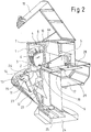
- FIG. 2 is a sectional perspective view of the device according to Fig. 1 shown.
- the same components are provided with the same reference numbers.
- the illustration shows the device after inserting the knife 26 in the magazine.
- the knives 26 are each applied with their cutting edge to the contact surface 13 of the knife system 11.
- the lifting cylinder 27 By the lifting cylinder 27, the stored on the support surface 12 knives 26 can be moved along the contact surface 13.
- a removal device 28 is provided, which has a holding magnet 29 for receiving the knife and a barrier 30 is assigned to store the knife.
- Fig. 3 is a partially sectioned plan view of the magazine shown.
- the same components are provided with the same reference numbers.
- the knives 26 are applied to the contact surface 13 of the knife system 11.
- the contour of the contact surface 13 is adapted to the contour of the cutting edge of the blade 26. Lateral slipping is prevented by the lateral boundary 14 of the knife system 11.
- Fig. 4 is a partially cutaway perspective view of the device after inserting the knife shown in the closed state.
- the support surface 12 is not yet moved up.
- the knives are positioned on the support surface 12 and pressed by the lifting cylinder 27 along the contact surface 13 against the counterpart 16. As a result, the uppermost knife for the grinding process is fixed in each case.
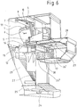
- Fig. 5 is a partially cutaway perspective view of the device shown.
- the removal unit 28 To remove the uppermost knife from the magazine, the removal unit 28 is moved horizontally in the direction of the magazine.
- the removal unit 28 with the holding magnet 29 for receiving a knife is positioned above the knives 26.
- the uppermost knife By moving the support surface 12 through the lifting cylinder 27 in the direction of the removal unit 28, the uppermost knife is attracted by the holding magnet 29.
- the removal device 28 is moved with the recorded knife in the starting position of the removal device.
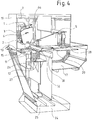
- Fig. 6 is a partially cutaway perspective view of the device shown.
- the knives 26 "were removed from the magazine by the removal device 28 and deposited on the storage surface 17.
- the knife 26 ' is still held in place by the holding magnet below the removal device 28.
- the barrier 30 of the removal device 28 is approached from below.
- the barrier 30 is so far approximated to the removal device 28, that the knife 26 'is stripped at her from the magnet and is positioned on the Messerablagestapel. From here, the blades 26 "can be removed from the storage surface 17.
Landscapes
- Engineering & Computer Science (AREA)
- Mechanical Engineering (AREA)
- Finish Polishing, Edge Sharpening, And Grinding By Specific Grinding Devices (AREA)
Priority Applications (1)
| Application Number | Priority Date | Filing Date | Title |
|---|---|---|---|
| PL14171344T PL2810738T3 (pl) | 2013-06-07 | 2014-06-05 | Urządzenie do ostrzenia co najmniej jednego noża |
Applications Claiming Priority (1)
| Application Number | Priority Date | Filing Date | Title |
|---|---|---|---|
| DE202013005156U DE202013005156U1 (de) | 2013-06-07 | 2013-06-07 | Vorrichtung zum Schleifen wenigstens eines Messers |
Publications (2)
| Publication Number | Publication Date |
|---|---|
| EP2810738A1 EP2810738A1 (de) | 2014-12-10 |
| EP2810738B1 true EP2810738B1 (de) | 2016-12-21 |
Family
ID=49232500
Family Applications (1)
| Application Number | Title | Priority Date | Filing Date |
|---|---|---|---|
| EP14171344.6A Active EP2810738B1 (de) | 2013-06-07 | 2014-06-05 | Vorrichtung zum Schleifen wenigstens eines Messers |
Country Status (3)
| Country | Link |
|---|---|
| EP (1) | EP2810738B1 (pl) |
| DE (1) | DE202013005156U1 (pl) |
| PL (1) | PL2810738T3 (pl) |
Families Citing this family (5)
| Publication number | Priority date | Publication date | Assignee | Title |
|---|---|---|---|---|
| DE102013217137A1 (de) * | 2013-08-28 | 2015-03-05 | Weber Maschinenbau Gmbh Breidenbach | Vorrichtung und Verfahren zum Schleifen von Rotationsmessern |
| NL2015561B1 (en) | 2015-10-05 | 2017-05-01 | Forage Innovations Bv | Grinding device and grinding method wherein a grinding unit can operate on-board as well as off-board. |
| NL2015562B1 (en) | 2015-10-05 | 2017-05-01 | Forage Innovations Bv | Grinding unit with a grinding head comprising a shaft and a shaft guiding assembly. |
| CN107498401A (zh) * | 2017-09-14 | 2017-12-22 | 福建大吉刀剪五金有限公司 | 一种自动剪刀磨面机 |
| CN109648437B (zh) * | 2018-12-18 | 2020-11-20 | 涡阳县顺隆智能科技有限公司 | 一种合金新材料加工设备 |
Family Cites Families (6)
| Publication number | Priority date | Publication date | Assignee | Title |
|---|---|---|---|---|
| DE4023071A1 (de) * | 1990-07-20 | 1992-01-23 | Feiffer Masch Anlagen | Schleifgeraet |
| DE10124319A1 (de) * | 2001-05-17 | 2002-11-21 | Knecht Maschb Gmbh | Vorrichtung zum Schleifen von Cuttermessern |
| DE10352328A1 (de) * | 2003-06-25 | 2005-01-13 | Gebr. Pöttinger GmbH | Messerschleifmaschine |
| DE20314680U1 (de) * | 2003-09-20 | 2003-11-20 | Oerlikon Geartec AG, Zürich | Schleifmaschine mit Messsystem und Steuerung zum Bereitstellen eines Meistermessers |
| DE202004009498U1 (de) * | 2004-06-17 | 2004-09-16 | Maschinenfabrik Bernard Krone Gmbh | Schleifvorrichtung für Schneidmesser landwirtschaftlicher Erntemaschinen |
| DE102011103418A1 (de) * | 2011-06-06 | 2012-12-06 | Weber Maschinenbau Gmbh Breidenbach | Vorrichtung und Verfahren zum Schleifen von Rotationsmessern |
-
2013
- 2013-06-07 DE DE202013005156U patent/DE202013005156U1/de not_active Expired - Lifetime
-
2014
- 2014-06-05 EP EP14171344.6A patent/EP2810738B1/de active Active
- 2014-06-05 PL PL14171344T patent/PL2810738T3/pl unknown
Non-Patent Citations (1)
| Title |
|---|
| None * |
Also Published As
| Publication number | Publication date |
|---|---|
| EP2810738A1 (de) | 2014-12-10 |
| PL2810738T3 (pl) | 2017-08-31 |
| DE202013005156U1 (de) | 2013-08-23 |
Similar Documents
| Publication | Publication Date | Title |
|---|---|---|
| EP2810738B1 (de) | Vorrichtung zum Schleifen wenigstens eines Messers | |
| DE60101290T2 (de) | Schleifvorrichtung zum gleichzeitigen Schleifen der vier Kanten einer Glasscheibe | |
| DE102010019852A1 (de) | Vorrichtung zum Schleifen von Handmessern | |
| DE3630175A1 (de) | Polier- oder schleifvorrichtung fuer optische faserbuendel | |
| EP2394783A1 (de) | Spitzenlose Rundschleifmaschine, Anordnung und Verfahren zum spitzenlosen Schleifen mit höhenverstellbarer Regelscheibe | |
| DE112005003796T5 (de) | Halsabschnittsschleifgerät, Schleifvorrichtung im Einsatz in dem Halsabschnittsschleifgerät und Halsabschnittsschleifverfahren | |
| DE19736801A1 (de) | Werkzeugmaschinenbauteil mit Schneidwerkzeug und darüber angeordnetem Werkstückträgerwagen | |
| DE102008017482A1 (de) | Vorrichtung zum Bearbeiten eines Werkstückes | |
| DE102009037298B4 (de) | Anordnung und Verfahren zum Schärfen eines Sägeblattes sowie Verwendung der Anordnung | |
| DE3830856C1 (pl) | ||
| DE202009015567U1 (de) | Vollautomatisches Schleifgerät zum Nassschleifen von Schneidmessern in landwirtschaftlichen Maschinen, insbesondere Pressen und Ladewagen | |
| DE10352328A1 (de) | Messerschleifmaschine | |
| DE102019000670A1 (de) | Transport-und Beladevorrichtung | |
| DE3637758A1 (de) | Verfahren und vorrichtung zum tiefschleifen | |
| DE102011052531A1 (de) | Verfahren zum Schleifen von Messern und Verschleißplatten eines Messerringzerspaners | |
| DE257549C (pl) | ||
| DE202019105860U1 (de) | Schleifeinrichtung zum Schleifen mindestens eines Messers mit mindestens einem Schleifstein | |
| DE102004062374B4 (de) | Verfahren und Vorrichtung zum automatischen Bearbeiten von nichtmetallischen, nachgiebigen Werkstücken | |
| DE202004009498U1 (de) | Schleifvorrichtung für Schneidmesser landwirtschaftlicher Erntemaschinen | |
| DE68913751T2 (de) | Schleifvorrichtung für die messer einer querschneidrolle. | |
| DE2829788A1 (de) | Schleifmaschine | |
| DE1657218C3 (de) | Aufschnittschneidmaschine | |
| DE2722523A1 (de) | Werkzeug-schleifmaschine | |
| DE576948C (de) | Schleifmaschine, insbesondere zum Schleifen von Hobelmessern | |
| AT500570B1 (de) | Messerschleifmaschine |
Legal Events
| Date | Code | Title | Description |
|---|---|---|---|
| PUAI | Public reference made under article 153(3) epc to a published international application that has entered the european phase |
Free format text: ORIGINAL CODE: 0009012 |
|
| 17P | Request for examination filed |
Effective date: 20140605 |
|
| AK | Designated contracting states |
Kind code of ref document: A1 Designated state(s): AL AT BE BG CH CY CZ DE DK EE ES FI FR GB GR HR HU IE IS IT LI LT LU LV MC MK MT NL NO PL PT RO RS SE SI SK SM TR |
|
| AX | Request for extension of the european patent |
Extension state: BA ME |
|
| R17P | Request for examination filed (corrected) |
Effective date: 20150527 |
|
| RBV | Designated contracting states (corrected) |
Designated state(s): AL AT BE BG CH CY CZ DE DK EE ES FI FR GB GR HR HU IE IS IT LI LT LU LV MC MK MT NL NO PL PT RO RS SE SI SK SM TR |
|
| 17Q | First examination report despatched |
Effective date: 20151013 |
|
| GRAP | Despatch of communication of intention to grant a patent |
Free format text: ORIGINAL CODE: EPIDOSNIGR1 |
|
| INTG | Intention to grant announced |
Effective date: 20160801 |
|
| GRAS | Grant fee paid |
Free format text: ORIGINAL CODE: EPIDOSNIGR3 |
|
| GRAA | (expected) grant |
Free format text: ORIGINAL CODE: 0009210 |
|
| AK | Designated contracting states |
Kind code of ref document: B1 Designated state(s): AL AT BE BG CH CY CZ DE DK EE ES FI FR GB GR HR HU IE IS IT LI LT LU LV MC MK MT NL NO PL PT RO RS SE SI SK SM TR |
|
| REG | Reference to a national code |
Ref country code: GB Ref legal event code: FG4D Free format text: NOT ENGLISH |
|
| REG | Reference to a national code |
Ref country code: CH Ref legal event code: EP |
|
| REG | Reference to a national code |
Ref country code: IE Ref legal event code: FG4D Free format text: LANGUAGE OF EP DOCUMENT: GERMAN |
|
| REG | Reference to a national code |
Ref country code: AT Ref legal event code: REF Ref document number: 855050 Country of ref document: AT Kind code of ref document: T Effective date: 20170115 |
|
| REG | Reference to a national code |
Ref country code: DE Ref legal event code: R096 Ref document number: 502014002238 Country of ref document: DE |
|
| PG25 | Lapsed in a contracting state [announced via postgrant information from national office to epo] |
Ref country code: LV Free format text: LAPSE BECAUSE OF FAILURE TO SUBMIT A TRANSLATION OF THE DESCRIPTION OR TO PAY THE FEE WITHIN THE PRESCRIBED TIME-LIMIT Effective date: 20161221 |
|
| REG | Reference to a national code |
Ref country code: NL Ref legal event code: FP |
|
| REG | Reference to a national code |
Ref country code: LT Ref legal event code: MG4D |
|
| PG25 | Lapsed in a contracting state [announced via postgrant information from national office to epo] |
Ref country code: GR Free format text: LAPSE BECAUSE OF FAILURE TO SUBMIT A TRANSLATION OF THE DESCRIPTION OR TO PAY THE FEE WITHIN THE PRESCRIBED TIME-LIMIT Effective date: 20170322 Ref country code: SE Free format text: LAPSE BECAUSE OF FAILURE TO SUBMIT A TRANSLATION OF THE DESCRIPTION OR TO PAY THE FEE WITHIN THE PRESCRIBED TIME-LIMIT Effective date: 20161221 Ref country code: LT Free format text: LAPSE BECAUSE OF FAILURE TO SUBMIT A TRANSLATION OF THE DESCRIPTION OR TO PAY THE FEE WITHIN THE PRESCRIBED TIME-LIMIT Effective date: 20161221 Ref country code: NO Free format text: LAPSE BECAUSE OF FAILURE TO SUBMIT A TRANSLATION OF THE DESCRIPTION OR TO PAY THE FEE WITHIN THE PRESCRIBED TIME-LIMIT Effective date: 20170321 |
|
| PG25 | Lapsed in a contracting state [announced via postgrant information from national office to epo] |
Ref country code: RS Free format text: LAPSE BECAUSE OF FAILURE TO SUBMIT A TRANSLATION OF THE DESCRIPTION OR TO PAY THE FEE WITHIN THE PRESCRIBED TIME-LIMIT Effective date: 20161221 Ref country code: FI Free format text: LAPSE BECAUSE OF FAILURE TO SUBMIT A TRANSLATION OF THE DESCRIPTION OR TO PAY THE FEE WITHIN THE PRESCRIBED TIME-LIMIT Effective date: 20161221 Ref country code: HR Free format text: LAPSE BECAUSE OF FAILURE TO SUBMIT A TRANSLATION OF THE DESCRIPTION OR TO PAY THE FEE WITHIN THE PRESCRIBED TIME-LIMIT Effective date: 20161221 |
|
| REG | Reference to a national code |
Ref country code: FR Ref legal event code: PLFP Year of fee payment: 4 |
|
| PG25 | Lapsed in a contracting state [announced via postgrant information from national office to epo] |
Ref country code: EE Free format text: LAPSE BECAUSE OF FAILURE TO SUBMIT A TRANSLATION OF THE DESCRIPTION OR TO PAY THE FEE WITHIN THE PRESCRIBED TIME-LIMIT Effective date: 20161221 Ref country code: CZ Free format text: LAPSE BECAUSE OF FAILURE TO SUBMIT A TRANSLATION OF THE DESCRIPTION OR TO PAY THE FEE WITHIN THE PRESCRIBED TIME-LIMIT Effective date: 20161221 Ref country code: SK Free format text: LAPSE BECAUSE OF FAILURE TO SUBMIT A TRANSLATION OF THE DESCRIPTION OR TO PAY THE FEE WITHIN THE PRESCRIBED TIME-LIMIT Effective date: 20161221 Ref country code: IS Free format text: LAPSE BECAUSE OF FAILURE TO SUBMIT A TRANSLATION OF THE DESCRIPTION OR TO PAY THE FEE WITHIN THE PRESCRIBED TIME-LIMIT Effective date: 20170421 Ref country code: RO Free format text: LAPSE BECAUSE OF FAILURE TO SUBMIT A TRANSLATION OF THE DESCRIPTION OR TO PAY THE FEE WITHIN THE PRESCRIBED TIME-LIMIT Effective date: 20161221 |
|
| PG25 | Lapsed in a contracting state [announced via postgrant information from national office to epo] |
Ref country code: PT Free format text: LAPSE BECAUSE OF FAILURE TO SUBMIT A TRANSLATION OF THE DESCRIPTION OR TO PAY THE FEE WITHIN THE PRESCRIBED TIME-LIMIT Effective date: 20170421 Ref country code: BG Free format text: LAPSE BECAUSE OF FAILURE TO SUBMIT A TRANSLATION OF THE DESCRIPTION OR TO PAY THE FEE WITHIN THE PRESCRIBED TIME-LIMIT Effective date: 20170321 Ref country code: SM Free format text: LAPSE BECAUSE OF FAILURE TO SUBMIT A TRANSLATION OF THE DESCRIPTION OR TO PAY THE FEE WITHIN THE PRESCRIBED TIME-LIMIT Effective date: 20161221 Ref country code: ES Free format text: LAPSE BECAUSE OF FAILURE TO SUBMIT A TRANSLATION OF THE DESCRIPTION OR TO PAY THE FEE WITHIN THE PRESCRIBED TIME-LIMIT Effective date: 20161221 |
|
| REG | Reference to a national code |
Ref country code: DE Ref legal event code: R097 Ref document number: 502014002238 Country of ref document: DE |
|
| PLBE | No opposition filed within time limit |
Free format text: ORIGINAL CODE: 0009261 |
|
| STAA | Information on the status of an ep patent application or granted ep patent |
Free format text: STATUS: NO OPPOSITION FILED WITHIN TIME LIMIT |
|
| 26N | No opposition filed |
Effective date: 20170922 |
|
| PG25 | Lapsed in a contracting state [announced via postgrant information from national office to epo] |
Ref country code: DK Free format text: LAPSE BECAUSE OF FAILURE TO SUBMIT A TRANSLATION OF THE DESCRIPTION OR TO PAY THE FEE WITHIN THE PRESCRIBED TIME-LIMIT Effective date: 20161221 |
|
| PG25 | Lapsed in a contracting state [announced via postgrant information from national office to epo] |
Ref country code: MC Free format text: LAPSE BECAUSE OF FAILURE TO SUBMIT A TRANSLATION OF THE DESCRIPTION OR TO PAY THE FEE WITHIN THE PRESCRIBED TIME-LIMIT Effective date: 20161221 |
|
| PG25 | Lapsed in a contracting state [announced via postgrant information from national office to epo] |
Ref country code: SI Free format text: LAPSE BECAUSE OF FAILURE TO SUBMIT A TRANSLATION OF THE DESCRIPTION OR TO PAY THE FEE WITHIN THE PRESCRIBED TIME-LIMIT Effective date: 20161221 |
|
| PG25 | Lapsed in a contracting state [announced via postgrant information from national office to epo] |
Ref country code: LU Free format text: LAPSE BECAUSE OF NON-PAYMENT OF DUE FEES Effective date: 20170605 |
|
| REG | Reference to a national code |
Ref country code: FR Ref legal event code: PLFP Year of fee payment: 5 |
|
| PG25 | Lapsed in a contracting state [announced via postgrant information from national office to epo] |
Ref country code: MT Free format text: LAPSE BECAUSE OF FAILURE TO SUBMIT A TRANSLATION OF THE DESCRIPTION OR TO PAY THE FEE WITHIN THE PRESCRIBED TIME-LIMIT Effective date: 20161221 |
|
| PG25 | Lapsed in a contracting state [announced via postgrant information from national office to epo] |
Ref country code: HU Free format text: LAPSE BECAUSE OF FAILURE TO SUBMIT A TRANSLATION OF THE DESCRIPTION OR TO PAY THE FEE WITHIN THE PRESCRIBED TIME-LIMIT; INVALID AB INITIO Effective date: 20140605 |
|
| PG25 | Lapsed in a contracting state [announced via postgrant information from national office to epo] |
Ref country code: CY Free format text: LAPSE BECAUSE OF FAILURE TO SUBMIT A TRANSLATION OF THE DESCRIPTION OR TO PAY THE FEE WITHIN THE PRESCRIBED TIME-LIMIT Effective date: 20161221 |
|
| PG25 | Lapsed in a contracting state [announced via postgrant information from national office to epo] |
Ref country code: MK Free format text: LAPSE BECAUSE OF FAILURE TO SUBMIT A TRANSLATION OF THE DESCRIPTION OR TO PAY THE FEE WITHIN THE PRESCRIBED TIME-LIMIT Effective date: 20161221 |
|
| REG | Reference to a national code |
Ref country code: DE Ref legal event code: R082 Ref document number: 502014002238 Country of ref document: DE Ref country code: DE Ref legal event code: R081 Ref document number: 502014002238 Country of ref document: DE Owner name: CLAAS SERVICE AND PARTS GMBH, DE Free format text: FORMER OWNER: SIEMER, ALFRED, 26689 APEN, DE |
|
| PG25 | Lapsed in a contracting state [announced via postgrant information from national office to epo] |
Ref country code: TR Free format text: LAPSE BECAUSE OF FAILURE TO SUBMIT A TRANSLATION OF THE DESCRIPTION OR TO PAY THE FEE WITHIN THE PRESCRIBED TIME-LIMIT Effective date: 20161221 |
|
| REG | Reference to a national code |
Ref country code: GB Ref legal event code: 732E Free format text: REGISTERED BETWEEN 20200423 AND 20200429 |
|
| REG | Reference to a national code |
Ref country code: BE Ref legal event code: PD Owner name: CLAAS SERVICE AND PARTS GMBH; DE Free format text: DETAILS ASSIGNMENT: CHANGE OF OWNER(S), CESSION; FORMER OWNER NAME: SIEMER, ALFRED Effective date: 20200402 |
|
| PG25 | Lapsed in a contracting state [announced via postgrant information from national office to epo] |
Ref country code: AL Free format text: LAPSE BECAUSE OF FAILURE TO SUBMIT A TRANSLATION OF THE DESCRIPTION OR TO PAY THE FEE WITHIN THE PRESCRIBED TIME-LIMIT Effective date: 20161221 |
|
| REG | Reference to a national code |
Ref country code: NL Ref legal event code: PD Owner name: CLAAS SERVICE AND PARTS GMBH; DE Free format text: DETAILS ASSIGNMENT: CHANGE OF OWNER(S), ASSIGNMENT; FORMER OWNER NAME: SIEMER, ALFRED Effective date: 20220422 |
|
| REG | Reference to a national code |
Ref country code: AT Ref legal event code: PC Ref document number: 855050 Country of ref document: AT Kind code of ref document: T Owner name: CLAAS SERVICE AND PARTS GMBH, DE Effective date: 20220323 |
|
| P01 | Opt-out of the competence of the unified patent court (upc) registered |
Effective date: 20230516 |
|
| PGFP | Annual fee paid to national office [announced via postgrant information from national office to epo] |
Ref country code: PL Payment date: 20250526 Year of fee payment: 12 Ref country code: DE Payment date: 20250618 Year of fee payment: 12 |
|
| PGFP | Annual fee paid to national office [announced via postgrant information from national office to epo] |
Ref country code: GB Payment date: 20250618 Year of fee payment: 12 |
|
| PGFP | Annual fee paid to national office [announced via postgrant information from national office to epo] |
Ref country code: NL Payment date: 20250618 Year of fee payment: 12 Ref country code: BE Payment date: 20250618 Year of fee payment: 12 |
|
| PGFP | Annual fee paid to national office [announced via postgrant information from national office to epo] |
Ref country code: FR Payment date: 20250624 Year of fee payment: 12 |
|
| PGFP | Annual fee paid to national office [announced via postgrant information from national office to epo] |
Ref country code: AT Payment date: 20250620 Year of fee payment: 12 |
|
| PGFP | Annual fee paid to national office [announced via postgrant information from national office to epo] |
Ref country code: IE Payment date: 20250618 Year of fee payment: 12 |
|
| PGFP | Annual fee paid to national office [announced via postgrant information from national office to epo] |
Ref country code: IT Payment date: 20250624 Year of fee payment: 12 |
|
| PGFP | Annual fee paid to national office [announced via postgrant information from national office to epo] |
Ref country code: CH Payment date: 20250701 Year of fee payment: 12 |
|
| REG | Reference to a national code |
Ref country code: CH Ref legal event code: R18 Free format text: ST27 STATUS EVENT CODE: U-0-0-R10-R18 (AS PROVIDED BY THE NATIONAL OFFICE) Effective date: 20260209 |
|
| REG | Reference to a national code |
Ref country code: CH Ref legal event code: R18 Free format text: ST27 STATUS EVENT CODE: U-0-0-R10-R18 (AS PROVIDED BY THE NATIONAL OFFICE) Effective date: 20260320 |