EP2806043B1 - Continuous annealing furnace and continuous annealing method for steel strips - Google Patents
Continuous annealing furnace and continuous annealing method for steel strips Download PDFInfo
- Publication number
- EP2806043B1 EP2806043B1 EP13738991.2A EP13738991A EP2806043B1 EP 2806043 B1 EP2806043 B1 EP 2806043B1 EP 13738991 A EP13738991 A EP 13738991A EP 2806043 B1 EP2806043 B1 EP 2806043B1
- Authority
- EP
- European Patent Office
- Prior art keywords
- furnace
- gas
- zone
- dew point
- disposed
- Prior art date
- Legal status (The legal status is an assumption and is not a legal conclusion. Google has not performed a legal analysis and makes no representation as to the accuracy of the status listed.)
- Active
Links
Images
Classifications
-
- C—CHEMISTRY; METALLURGY
- C21—METALLURGY OF IRON
- C21D—MODIFYING THE PHYSICAL STRUCTURE OF FERROUS METALS; GENERAL DEVICES FOR HEAT TREATMENT OF FERROUS OR NON-FERROUS METALS OR ALLOYS; MAKING METAL MALLEABLE, e.g. BY DECARBURISATION OR TEMPERING
- C21D9/00—Heat treatment, e.g. annealing, hardening, quenching or tempering, adapted for particular articles; Furnaces therefor
- C21D9/52—Heat treatment, e.g. annealing, hardening, quenching or tempering, adapted for particular articles; Furnaces therefor for wires; for strips ; for rods of unlimited length
- C21D9/54—Furnaces for treating strips or wire
- C21D9/56—Continuous furnaces for strip or wire
- C21D9/561—Continuous furnaces for strip or wire with a controlled atmosphere or vacuum
-
- C—CHEMISTRY; METALLURGY
- C21—METALLURGY OF IRON
- C21D—MODIFYING THE PHYSICAL STRUCTURE OF FERROUS METALS; GENERAL DEVICES FOR HEAT TREATMENT OF FERROUS OR NON-FERROUS METALS OR ALLOYS; MAKING METAL MALLEABLE, e.g. BY DECARBURISATION OR TEMPERING
- C21D1/00—General methods or devices for heat treatment, e.g. annealing, hardening, quenching or tempering
- C21D1/26—Methods of annealing
-
- C—CHEMISTRY; METALLURGY
- C21—METALLURGY OF IRON
- C21D—MODIFYING THE PHYSICAL STRUCTURE OF FERROUS METALS; GENERAL DEVICES FOR HEAT TREATMENT OF FERROUS OR NON-FERROUS METALS OR ALLOYS; MAKING METAL MALLEABLE, e.g. BY DECARBURISATION OR TEMPERING
- C21D9/00—Heat treatment, e.g. annealing, hardening, quenching or tempering, adapted for particular articles; Furnaces therefor
- C21D9/52—Heat treatment, e.g. annealing, hardening, quenching or tempering, adapted for particular articles; Furnaces therefor for wires; for strips ; for rods of unlimited length
- C21D9/54—Furnaces for treating strips or wire
- C21D9/56—Continuous furnaces for strip or wire
- C21D9/562—Details
-
- C—CHEMISTRY; METALLURGY
- C23—COATING METALLIC MATERIAL; COATING MATERIAL WITH METALLIC MATERIAL; CHEMICAL SURFACE TREATMENT; DIFFUSION TREATMENT OF METALLIC MATERIAL; COATING BY VACUUM EVAPORATION, BY SPUTTERING, BY ION IMPLANTATION OR BY CHEMICAL VAPOUR DEPOSITION, IN GENERAL; INHIBITING CORROSION OF METALLIC MATERIAL OR INCRUSTATION IN GENERAL
- C23C—COATING METALLIC MATERIAL; COATING MATERIAL WITH METALLIC MATERIAL; SURFACE TREATMENT OF METALLIC MATERIAL BY DIFFUSION INTO THE SURFACE, BY CHEMICAL CONVERSION OR SUBSTITUTION; COATING BY VACUUM EVAPORATION, BY SPUTTERING, BY ION IMPLANTATION OR BY CHEMICAL VAPOUR DEPOSITION, IN GENERAL
- C23C2/00—Hot-dipping or immersion processes for applying the coating material in the molten state without affecting the shape; Apparatus therefor
- C23C2/003—Apparatus
- C23C2/0034—Details related to elements immersed in bath
- C23C2/00342—Moving elements, e.g. pumps or mixers
- C23C2/00344—Means for moving substrates, e.g. immersed rollers or immersed bearings
-
- C—CHEMISTRY; METALLURGY
- C23—COATING METALLIC MATERIAL; COATING MATERIAL WITH METALLIC MATERIAL; CHEMICAL SURFACE TREATMENT; DIFFUSION TREATMENT OF METALLIC MATERIAL; COATING BY VACUUM EVAPORATION, BY SPUTTERING, BY ION IMPLANTATION OR BY CHEMICAL VAPOUR DEPOSITION, IN GENERAL; INHIBITING CORROSION OF METALLIC MATERIAL OR INCRUSTATION IN GENERAL
- C23C—COATING METALLIC MATERIAL; COATING MATERIAL WITH METALLIC MATERIAL; SURFACE TREATMENT OF METALLIC MATERIAL BY DIFFUSION INTO THE SURFACE, BY CHEMICAL CONVERSION OR SUBSTITUTION; COATING BY VACUUM EVAPORATION, BY SPUTTERING, BY ION IMPLANTATION OR BY CHEMICAL VAPOUR DEPOSITION, IN GENERAL
- C23C2/00—Hot-dipping or immersion processes for applying the coating material in the molten state without affecting the shape; Apparatus therefor
- C23C2/003—Apparatus
- C23C2/0035—Means for continuously moving substrate through, into or out of the bath
-
- C—CHEMISTRY; METALLURGY
- C23—COATING METALLIC MATERIAL; COATING MATERIAL WITH METALLIC MATERIAL; CHEMICAL SURFACE TREATMENT; DIFFUSION TREATMENT OF METALLIC MATERIAL; COATING BY VACUUM EVAPORATION, BY SPUTTERING, BY ION IMPLANTATION OR BY CHEMICAL VAPOUR DEPOSITION, IN GENERAL; INHIBITING CORROSION OF METALLIC MATERIAL OR INCRUSTATION IN GENERAL
- C23C—COATING METALLIC MATERIAL; COATING MATERIAL WITH METALLIC MATERIAL; SURFACE TREATMENT OF METALLIC MATERIAL BY DIFFUSION INTO THE SURFACE, BY CHEMICAL CONVERSION OR SUBSTITUTION; COATING BY VACUUM EVAPORATION, BY SPUTTERING, BY ION IMPLANTATION OR BY CHEMICAL VAPOUR DEPOSITION, IN GENERAL
- C23C2/00—Hot-dipping or immersion processes for applying the coating material in the molten state without affecting the shape; Apparatus therefor
- C23C2/003—Apparatus
- C23C2/0038—Apparatus characterised by the pre-treatment chambers located immediately upstream of the bath or occurring locally before the dipping process
-
- C—CHEMISTRY; METALLURGY
- C23—COATING METALLIC MATERIAL; COATING MATERIAL WITH METALLIC MATERIAL; CHEMICAL SURFACE TREATMENT; DIFFUSION TREATMENT OF METALLIC MATERIAL; COATING BY VACUUM EVAPORATION, BY SPUTTERING, BY ION IMPLANTATION OR BY CHEMICAL VAPOUR DEPOSITION, IN GENERAL; INHIBITING CORROSION OF METALLIC MATERIAL OR INCRUSTATION IN GENERAL
- C23C—COATING METALLIC MATERIAL; COATING MATERIAL WITH METALLIC MATERIAL; SURFACE TREATMENT OF METALLIC MATERIAL BY DIFFUSION INTO THE SURFACE, BY CHEMICAL CONVERSION OR SUBSTITUTION; COATING BY VACUUM EVAPORATION, BY SPUTTERING, BY ION IMPLANTATION OR BY CHEMICAL VAPOUR DEPOSITION, IN GENERAL
- C23C2/00—Hot-dipping or immersion processes for applying the coating material in the molten state without affecting the shape; Apparatus therefor
- C23C2/02—Pretreatment of the material to be coated, e.g. for coating on selected surface areas
- C23C2/022—Pretreatment of the material to be coated, e.g. for coating on selected surface areas by heating
- C23C2/0224—Two or more thermal pretreatments
-
- C—CHEMISTRY; METALLURGY
- C23—COATING METALLIC MATERIAL; COATING MATERIAL WITH METALLIC MATERIAL; CHEMICAL SURFACE TREATMENT; DIFFUSION TREATMENT OF METALLIC MATERIAL; COATING BY VACUUM EVAPORATION, BY SPUTTERING, BY ION IMPLANTATION OR BY CHEMICAL VAPOUR DEPOSITION, IN GENERAL; INHIBITING CORROSION OF METALLIC MATERIAL OR INCRUSTATION IN GENERAL
- C23C—COATING METALLIC MATERIAL; COATING MATERIAL WITH METALLIC MATERIAL; SURFACE TREATMENT OF METALLIC MATERIAL BY DIFFUSION INTO THE SURFACE, BY CHEMICAL CONVERSION OR SUBSTITUTION; COATING BY VACUUM EVAPORATION, BY SPUTTERING, BY ION IMPLANTATION OR BY CHEMICAL VAPOUR DEPOSITION, IN GENERAL
- C23C2/00—Hot-dipping or immersion processes for applying the coating material in the molten state without affecting the shape; Apparatus therefor
- C23C2/04—Hot-dipping or immersion processes for applying the coating material in the molten state without affecting the shape; Apparatus therefor characterised by the coating material
- C23C2/06—Zinc or cadmium or alloys based thereon
-
- C—CHEMISTRY; METALLURGY
- C23—COATING METALLIC MATERIAL; COATING MATERIAL WITH METALLIC MATERIAL; CHEMICAL SURFACE TREATMENT; DIFFUSION TREATMENT OF METALLIC MATERIAL; COATING BY VACUUM EVAPORATION, BY SPUTTERING, BY ION IMPLANTATION OR BY CHEMICAL VAPOUR DEPOSITION, IN GENERAL; INHIBITING CORROSION OF METALLIC MATERIAL OR INCRUSTATION IN GENERAL
- C23C—COATING METALLIC MATERIAL; COATING MATERIAL WITH METALLIC MATERIAL; SURFACE TREATMENT OF METALLIC MATERIAL BY DIFFUSION INTO THE SURFACE, BY CHEMICAL CONVERSION OR SUBSTITUTION; COATING BY VACUUM EVAPORATION, BY SPUTTERING, BY ION IMPLANTATION OR BY CHEMICAL VAPOUR DEPOSITION, IN GENERAL
- C23C2/00—Hot-dipping or immersion processes for applying the coating material in the molten state without affecting the shape; Apparatus therefor
- C23C2/26—After-treatment
- C23C2/28—Thermal after-treatment, e.g. treatment in oil bath
-
- C—CHEMISTRY; METALLURGY
- C23—COATING METALLIC MATERIAL; COATING MATERIAL WITH METALLIC MATERIAL; CHEMICAL SURFACE TREATMENT; DIFFUSION TREATMENT OF METALLIC MATERIAL; COATING BY VACUUM EVAPORATION, BY SPUTTERING, BY ION IMPLANTATION OR BY CHEMICAL VAPOUR DEPOSITION, IN GENERAL; INHIBITING CORROSION OF METALLIC MATERIAL OR INCRUSTATION IN GENERAL
- C23C—COATING METALLIC MATERIAL; COATING MATERIAL WITH METALLIC MATERIAL; SURFACE TREATMENT OF METALLIC MATERIAL BY DIFFUSION INTO THE SURFACE, BY CHEMICAL CONVERSION OR SUBSTITUTION; COATING BY VACUUM EVAPORATION, BY SPUTTERING, BY ION IMPLANTATION OR BY CHEMICAL VAPOUR DEPOSITION, IN GENERAL
- C23C2/00—Hot-dipping or immersion processes for applying the coating material in the molten state without affecting the shape; Apparatus therefor
- C23C2/34—Hot-dipping or immersion processes for applying the coating material in the molten state without affecting the shape; Apparatus therefor characterised by the shape of the material to be treated
- C23C2/36—Elongated material
- C23C2/40—Plates; Strips
-
- C—CHEMISTRY; METALLURGY
- C23—COATING METALLIC MATERIAL; COATING MATERIAL WITH METALLIC MATERIAL; CHEMICAL SURFACE TREATMENT; DIFFUSION TREATMENT OF METALLIC MATERIAL; COATING BY VACUUM EVAPORATION, BY SPUTTERING, BY ION IMPLANTATION OR BY CHEMICAL VAPOUR DEPOSITION, IN GENERAL; INHIBITING CORROSION OF METALLIC MATERIAL OR INCRUSTATION IN GENERAL
- C23C—COATING METALLIC MATERIAL; COATING MATERIAL WITH METALLIC MATERIAL; SURFACE TREATMENT OF METALLIC MATERIAL BY DIFFUSION INTO THE SURFACE, BY CHEMICAL CONVERSION OR SUBSTITUTION; COATING BY VACUUM EVAPORATION, BY SPUTTERING, BY ION IMPLANTATION OR BY CHEMICAL VAPOUR DEPOSITION, IN GENERAL
- C23C2/00—Hot-dipping or immersion processes for applying the coating material in the molten state without affecting the shape; Apparatus therefor
- C23C2/50—Controlling or regulating the coating processes
- C23C2/52—Controlling or regulating the coating processes with means for measuring or sensing
-
- F—MECHANICAL ENGINEERING; LIGHTING; HEATING; WEAPONS; BLASTING
- F27—FURNACES; KILNS; OVENS; RETORTS
- F27B—FURNACES, KILNS, OVENS OR RETORTS IN GENERAL; OPEN SINTERING OR LIKE APPARATUS
- F27B9/00—Furnaces through which the charge is moved mechanically, e.g. of tunnel type; Similar furnaces in which the charge moves by gravity
- F27B9/28—Furnaces through which the charge is moved mechanically, e.g. of tunnel type; Similar furnaces in which the charge moves by gravity for treating continuous lengths of work
-
- F—MECHANICAL ENGINEERING; LIGHTING; HEATING; WEAPONS; BLASTING
- F27—FURNACES; KILNS; OVENS; RETORTS
- F27D—DETAILS OR ACCESSORIES OF FURNACES, KILNS, OVENS OR RETORTS, IN SO FAR AS THEY ARE OF KINDS OCCURRING IN MORE THAN ONE KIND OF FURNACE
- F27D17/00—Arrangements for using waste heat; Arrangements for using, or disposing of, waste gases
- F27D17/10—Arrangements for using waste heat
-
- C—CHEMISTRY; METALLURGY
- C21—METALLURGY OF IRON
- C21D—MODIFYING THE PHYSICAL STRUCTURE OF FERROUS METALS; GENERAL DEVICES FOR HEAT TREATMENT OF FERROUS OR NON-FERROUS METALS OR ALLOYS; MAKING METAL MALLEABLE, e.g. BY DECARBURISATION OR TEMPERING
- C21D9/00—Heat treatment, e.g. annealing, hardening, quenching or tempering, adapted for particular articles; Furnaces therefor
- C21D9/52—Heat treatment, e.g. annealing, hardening, quenching or tempering, adapted for particular articles; Furnaces therefor for wires; for strips ; for rods of unlimited length
- C21D9/54—Furnaces for treating strips or wire
- C21D9/56—Continuous furnaces for strip or wire
- C21D9/573—Continuous furnaces for strip or wire with cooling
Definitions
- the present invention relates to continuous annealing furnaces and continuous annealing methods for steel strips.
- a conventional method that is widely performed is to raise the furnace temperature in order to vaporize the water in the furnace and, almost at the same time, to supply a non-oxidizing gas, for example, an inert gas as a purging gas to replace the atmosphere in the furnace while evacuating the gas in the furnace simultaneously, thereby purging the atmosphere in the furnace with the non-oxidizing gas.
- a non-oxidizing gas for example, an inert gas as a purging gas to replace the atmosphere in the furnace while evacuating the gas in the furnace simultaneously, thereby purging the atmosphere in the furnace with the non-oxidizing gas.
- high-tensile strength steel capable of contributing to enhancements such as of weight reduction of structures.
- silicon in this high tensile technology, it is presented that the addition of silicon to steel possibly allows for manufacturing of high-tensile strength steel strips with good hole expandability, and further, the addition of silicon and aluminum facilitates the formation of retained ⁇ , indicating the possibility that steel strips with good ductility may be produced.
- silicon is highly detrimental to coating properties and alloying treatments because a SiO 2 film formed on the surface of a steel strip markedly lowers the wettability of the steel strip with respect to a hot dip coating metal and also because a SiO 2 film serves as a barrier during an alloying treatment to inhibit the interdiffusion between the base iron and the coating metal.
- a possible approach to preventing such problems is to control the oxygen potential in the annealing atmosphere.
- Patent Literature 1 discloses a method in which the dew point in a latter half of a heating zone and in a soaking zone is controlled to a high dew point of -30°C or above.
- This technique is expected to achieve effects to some degree and has an advantage that a high dew point may be controlled easily on the industrial scale.
- the technique is defective in that it does not allow for efficient production of some types of steel that do not favor being processed in a high-dew point atmosphere (for example, Ti-containing IF steel) because an annealing atmosphere once brought to a high dew point requires a very long time to become one having a low dew point.
- the furnace atmosphere is oxidative and, unless controlled appropriately, causes a problem of pick-up defects due to the attachment of oxides to rolls in the furnace as well as a problem of damage to the furnace walls.
- Patent Literature 2 and Patent Literature 3 disclose techniques for efficiently obtaining a low-dew point annealing atmosphere. These techniques reside in relatively small, single-pass vertical furnaces and are not designed to be applied to multi-pass vertical furnaces such as CGL and CAL systems. Thus, it is highly probable that these techniques will fail to decrease the dew point efficiently in a multi-pass vertical furnace.
- the heating zone and the soaking zone are physically separated from each other by a partition wall disposed therebetween except for traveling routes for a steel strip.
- Other such furnaces have no partition wall between the heating zone and the soaking zone, namely, the heating zone and the soaking zone are not physically separated from each other.
- the absence of a partition wall between the heating zone and the soaking zone allows the gas in the furnace to flow with a higher degree of freedom and with higher complexity. Thus, difficulties are frequently encountered in decreasing the dew point in the entirety of the furnace.
- a vertical annealing furnace including a heating zone, a soaking zone, and a cooling zone is used in which a portion of gas in the furnace is introduced into a refiner that is disposed outside of the furnace to decrease the dew point of the gas and the gas whose dew point has been decreased is returned into the furnace.
- a connection part between the soaking zone and the cooling zone is disposed in an upper portion of the furnace.
- Suction ports through which the gas in the furnace is sucked so as to be introduced into the refiner are disposed in a portion of the cooling zone near the connection part between the soaking zone and the cooling zone and in an upper portion of the soaking zone.
- Feed ports through which the gas from the refiner is returned to the furnace are disposed in the connection part between the soaking zone and the cooling zone and in a lower portion of the soaking zone.
- JP H09 324210 A provides a method for producing a hot dip galvanized steel sheet which is constituted in such a manner that a hot rolled steel sheet 1 having an iron oxide layer on the surface is reduced by heating zones 3 and 4 in an annealing furnace 2, is thereafter immersed in a hot dip galvanizing tank 10 arranged connectedly to the annealing furnace 2 and is applied with plating.
- the reduction is executed in such a manner that the atmospheric gas of the heating zones is dehumidified, and the raise of the dew point of the atmospheric gas is suppressed.
- the annealing furnace 2 having the heating zones 3 and 4 reducing the steel sheet, the hot dip galvanizing tank 10 arranged connectedly to the annealing furnace 2 and a dehumidifying device 20 for dehumidifying the atmospheric gas of the heating zones are arranged.
- JP 2003 129125 A discloses a continuous heat treatment furnace for strip, which is provided with sealing chambers 7 and 8 that are respectively partitioned with seal rolls 9 and 10, and 15 and 16, in an inlet and an outlet of a metal strip 2, supplies the atmospheric gas into the furnace body along with supplying a seal gas to each sealing chamber, and is provided with an atmospheric gas regenerator 30 that forcibly sucks gas in the furnace from the vicinity of the seal chamber 7 at the inlet side in the furnace body, and regenerates and circulates the gas in the furnace to the furnace body, this continuous heat treatment furnace is characterized by arranging a densitometer 31 for detecting the atmosphere gas concentration in upstream of the atmosphere gas regenerator, and a dew point recorder 32 in the vicinity of an inlet of a cooling zone 6 in the furnace body for detecting a dew point of gas in the furnace, and controlling the supply of the atmosphere gas so as to keep the concentration and the dew point each to a predetermined value.
- An object of the present invention is to provide a continuous annealing furnace for steel strips which can lower quickly the dew point of the furnace atmosphere to a level suited for steady operation, prior to the steady operation of continuous heat treatment of the steel strips or, when the water concentration and/or the oxygen concentration in the furnace atmosphere has increased during the steady operation.
- the present invention has an object of providing a continuous annealing furnace for steel strips which can stably create a low-dew point atmosphere having little problems in terms of the occurrence of pick-up defects and damages to furnace walls, which prevents the formation of oxides of easily oxidizable elements such as silicon and manganese in the steel that have become concentrated at the surface of steel strips during annealing, and which is hence suited for the annealing of steel strips containing easily oxidizable elements such as silicon.
- the invention has an object of providing a continuous annealing furnace to be disposed in a continuous hot dip galvanization line in which a steel strip is continuously annealed and is thereafter subjected to hot dip galvanization or, after the hot dip galvanization, further to an alloying treatment for the zing coating.
- the invention has a further object of providing a continuous annealing method for steel strips which involves the aforementioned continuous annealing furnace.
- the inventive technique is applied to continuous annealing furnaces in which a heating zone and a soaking zone in the annealing furnace are not physically separated from each other by a partition wall, and the soaking zone is in communication with a cooling zone at an upper portion of the furnace.
- the present inventors have carried out studies including the measurement of dew point distribution in a large multi-pass vertical furnace and rheological analysis based on the distribution. As a result, the present inventors have found the following. Because steam (H 2 O) has a lower specific gravity than N 2 gas which occupies the major proportion of the atmosphere, the dew point in a multi-pass vertical annealing furnace tends to be higher at an upper portion in the furnace.
- steam H 2 O
- a local increase in the dew point at an upper portion of the furnace can be prevented and the dew point of the furnace atmosphere can be decreased in a short time to a prescribed level suited for steady operation by suctioning and sending the gas in the furnace through an upper part of the furnace into a refiner equipped with an oxygen removal device and a dehumidifier to lower the dew point by the removal of oxygen and water, and thereafter returning the gas having the lowered dew point into a specific section in the furnace.
- the dew point of the furnace atmosphere can be stably maintained at a low level where little problems occur in terms of pick-up defects and damages to furnace walls and also at which the formation is prevented of oxides of easily oxidizable elements such as silicon and manganese in the steel that have become concentrated at the surface of steel strips during annealing.
- the continuous annealing furnace for steel strips Prior to the steady operation of continuous heat treatment of a steel strip or when the water concentration and/or the oxygen concentration in the furnace atmosphere has increased during the steady operation, the continuous annealing furnace for steel strips according to the present invention can shorten a period of time that the water concentration and/or the oxygen concentration in the furnace atmosphere is reduced to such a level where the dew point of the furnace atmosphere is lowered to -30°C or below, permitting stable production of steel strips.
- the inventive furnace prevents a decrease in productivity.
- the inventive furnace for continuous annealing of steel strips allows the furnace atmosphere to stably maintain a low dew point of -40°C or below where little problems occur in terms of pick-up defects and damages to furnace walls and also at which the formation is prevented of oxides of easily oxidizable elements such as silicon and manganese in the steel that have become concentrated at the surface of steel strips during annealing. Further, the inventive furnace for continuous annealing of steel strips allows for easy manufacturing of steels such as Ti-containing IF steel which do not favor operation in a high-dew point atmosphere.
- a continuous hot dip galvanization line for steel strips includes an annealing furnace upstream to a coating bath.
- the annealing furnace includes a heating zone, a soaking zone and a cooling zone disposed in this order from the upstream to the downstream of the furnace.
- a preheating zone may be sometimes disposed upstream to the heating zone.
- the annealing furnace is connected to the coating bath via a snout.
- the inside of the furnace extending from the heating zone to the snout is maintained in a reducing atmosphere gas or in a non-oxidizing atmosphere.
- the heating zone and the soaking zone involve radiant tubes (RT) as heating units to indirectly heat the steel strip.
- RT radiant tubes
- the reducing atmosphere gas is usually H 2 -N 2 gas and is introduced into appropriate positions inside the furnace between the heating zone and the snout.
- the steel strip is heated and annealed at prescribed temperatures in the heating zone and the soaking zone, then cooled in the cooling zone, then transported through the snout into the coating bath in which the steel strip is hot dip galvanized, and optionally further subjected to galvannealing.
- the furnace in the continuous hot dip galvanization line (CGL) is connected to the coating bath via the snout, the gas introduced into the furnace is discharged through the entrance of the furnace except for unavoidable gas escape such as leakage from the furnace body. That is, the gas in the furnace flows from the downstream to the upstream of the furnace reverse to the direction in which the steel strip is moved. Because steam (H 2 O) has a lower specific gravity than N 2 gas which occupies the major proportion of the atmosphere, the dew point in a multi-pass vertical annealing furnace tends to be higher at an upper portion in the furnace.
- the atmosphere gas in the furnace do not stagnate (the atmosphere gas do not stagnate at an upper portion, a middle portion and a lower portion in the furnace) so that the dew point will not increase in the upper portion of the furnace. It is also important to know sources of water that increases the dew point. Possible sources of water (H 2 O) are furnace walls, steel strips, entry of outside air through the furnace entrance, and entry of water from the cooling zone and the snout. Leaks in radiant tubes and in furnace walls can possibly serve as water supply sources.
- the dew point exerts larger influences on coating properties with increasing temperature of the steel strip.
- the influences become particularly marked when the steel strip temperature is in the range of 700°C and above in which the steel strip shows higher reactivity with oxygen. Accordingly, the dew point in the latter half of the heating zone and in the soaking zone where the steel strip has an elevated temperature will significantly affect coating properties.
- the atmosphere is continuous from the heating zone to the soaking zone and this fact requires that the dew point be efficiently reduced in the entire region of the furnace including the heating zone and the soaking zone
- dew point reduction is appropriately performed only in a region where the steel strip has a high temperature.
- a furnace having a heating zone and a soaking zone which are not separated from each other causes a difficulty in lowering the dew point locally in the heating zone or the soaking zone.
- dew point reduction should be carried out in the entirety of the heating zone and the soaking zone.
- a lower dew point is more advantageous in terms of coating properties.
- the dew point of the atmosphere gas is decreased by introducing part of the atmosphere gas in the furnace to a refiner disposed outside the furnace which has an oxygen removal device and a dehumidifier to lower the dew point by the removal of oxygen and water in the gas, and thereafter returning the gas having the lowered dew point into the furnace.
- This process involves the following arrangements 1) to 3) of gas suction openings through which the gas in the furnace is introduced into the refiner, and gas ejection openings through which the gas having the lowered dew point is returned from the refiner into the furnace.
- the ejection width W0 of the gas ejection openings in the upper portion of the heating zone preferably satisfies WO/W > 1/4 wherein W is the furnace width of the heating zone plus the soaking zone (the total furnace width).
- the ejection width W0 of the gas ejection openings in the heating zone is the distance in the furnace length direction between the most upstream gas ejection opening and the most downstream gas ejection opening in the heating zone (see Fig. 2 ).
- the present invention is based on the above viewpoints.
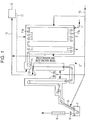
- Fig. 1 illustrates an exemplary configuration of a continuous hot dip galvanization line for a steel strip which includes a vertical annealing furnace used for the implementation of the present invention.
- reference sign 1 denotes a steel strip.
- An annealing furnace 2 includes a heating zone 3, a soaking zone 4 and a cooling zone 5 disposed in this order in the direction of the travel of the steel strip.
- a plurality of upper hearth rolls 11a and lower hearth rolls 11b are disposed so as to constitute multiple passes in which the steel strip 1 is transported a plurality of times in upward and downward directions.
- Radiant tubes are used as heating units to indirectly heat the steel strip 1.
- a snout 6, a coating bath 7, gas wiping nozzles 8, a galvannealing heating device 9, and a refiner 10 which deoxidizes and dehumidifies the atmosphere gas suctioned from the inside of the furnace.
- a joint 13 between the soaking zone 4 and the cooling zone 5 is disposed in an upper portion of the furnace above the cooling zone 5.
- a roll is disposed which guides the steel strip 1 delivered from the soaking zone 4 to travel in a downward direction.
- the exit at a lower portion of the joint that continues to the cooling zone 5 defines a throat section (a throat-like structure having a smaller sectional area of the steel strip channel) and seal rolls 12 are disposed in the throat section 14.
- the cooling zone 5 is composed of a first cooling zone 5a and a second cooling zone 5b.
- the first cooling zone 5a has a single pass for the steel strip.
- Reference sign 15 denotes an atmosphere gas supply system 15, through which an atmosphere gas is supplied from the outside to the inside of the furnace and the atmosphere gas is fed into the refiner 10 through a gas introduction pipe 16 and out of the refiner 10 through a gas delivery pipe 17.
- the feed rates and the supply of the atmosphere gas into the heating zone 3, the soaking zone 4, the cooling zone 5 and subsequent zones in the furnace may be individually adjusted or terminated with use of valves (not shown) and flow meters (not shown) disposed in the course of the atmosphere gas supply system 15 to the respective zones.
- a usual atmosphere gas supplied into the furnace has a composition including 1 to 10 vol% H 2 and the balance of N 2 and inevitable impurities. The dew point of such an atmosphere gas is about -60°C.
- Gas suction openings to introduce the furnace gas into the refiner are disposed in a choked gas flow channel in a lower portion of the joint 13 between the soaking zone 4 and the cooling zone 5, for example, the throat section 14, and also in the heating zone 3 and/or the soaking zone 4 except a region extending 6 m in the vertical direction and 3 m in the furnace length direction both from a steel strip inlet at a lower portion of the heating zone 3 (see Fig. 2 ).
- the suction openings are disposed in a plurality of positions in the heating zone 3 and/or the soaking zone 4. When seal rolls are disposed in the throat section 14, the width of gas flow channel is even narrower in that location and therefore the placement of the gas suction opening at or in the vicinity of the location is more desirable.
- Gas ejection openings to return a gas whose dew point has been decreased in the refiner back into the furnace are disposed in the joint 13 between the soaking zone 4 and the cooling zone 5 and also in the heating zone 3.
- the gas ejection opening in the joint 13 between the soaking zone 4 and the cooling zone 5 is disposed above the pass line.
- the gas ejection opening in the heating zone 3 is disposed in a region located above a position 2 m below the center of the upper hearth rolls in the heating zone 3 in the vertical direction.
- the gas ejection openings are disposed in a plurality of positions in the heating zone.
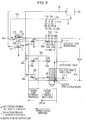
- Fig. 2 illustrates an example of arrangement of the gas suction openings and the gas ejection openings for the delivery of the gas into and out of the refiner 10.
- Reference signs 22a to 22e denote furnace-to-refiner gas suction openings.
- Reference signs 23a to 23e denote refiner-to-furnace gas ejection openings.
- Reference sign 24 denotes a dew point detection unit.
- the furnace width of the heating zone is 12 m
- the furnace width of the soaking zone is 4 m
- the furnace width of the heating zone plus the soaking zone is 16 m.
- the furnace-to-refiner gas suction openings have a diameter of 200 mm.
- a single opening (22e) is disposed in the throat section that is a lower portion of the joint 13 between the soaking zone 3 and the cooling zone 4.
- a total of four pairs (22a to 22d) that are each a pair of two suction openings 1 m away from each other in the furnace length direction are disposed, one at 1 m below the center of the upper hearth rolls in the soaking zone, one at 1/2 of the furnace height in the soaking zone (at the center in the height direction), one at 1 m above the center of the lower hearth rolls in the soaking zone, and one in the center of the heating zone (at 1/2 of the furnace height and in the middle in the furnace length direction).
- the refiner-to-furnace gas ejection openings have a diameter of 50 mm.
- One (23e) is disposed in an exit-side furnace wall of the joint between the soaking zone and the cooling zone, specifically, at 1 m above the pass line and 1 m below the ceiling wall.
- Other four (23a to 23d) are disposed 1 m below the center of the upper hearth rolls in the heating zone with intervals of 2 m in the furnace length direction, starting from the position in the heating zone that is 1 m away from the entrance-side furnace wall.
- the dew point detection units 24 of dew point meters are configured to detect the dew points of the gas in the furnace.
- the units are disposed in the joint between the soaking zone and the cooling zone, in the middle between the respective two suction openings disposed in the soaking zone and the heating zone, and in the middle between the third and fourth ejection openings in the heating zone counted from the entrance-side furnace wall (in the middle between the ejection openings 23c and 23d).
- the atmosphere gas suction openings are disposed in a plurality of positions in the heating zone and the soaking zone for the following reasons.
- the distribution of dew point in the furnace varies significantly depending on the status in the furnace (for example, the degree of breakage of the radiant tubes and the seals in the furnace body). It is however the case that the presence of a partition wall limits the flow of gas in the furnace to make it easy to determine where the refiner-to-furnace gas ejection opening and the furnace-to-refiner gas suction opening should be disposed in order to efficiently decrease the dew point.
- the flow of gas in the furnace becomes complicated and the locations of the suction opening and the ejection opening connected to or from the refiner need to be changed in accordance with the status of the dew point.
- the suction opening needs to be disposed in a position where the atmosphere has a higher dew point because otherwise the furnace cannot be dehumidified efficiently, resulting in a failure to obtain the desired dew point or a need for increasing the size of the furnace facility.
- the gas suction openings in a plurality of positions, the gas can be efficiently suctioned from the position where the dew point is high.
- the dew point may be decreased to the desired level without involving a large furnace facility.
- the atmosphere gas suctioned through the gas suction opening may be introduced into the refiner through any of furnace-to-refiner gas introduction pipes 16a to 16e and through a furnace-to-refiner gas introduction pipe 16.
- the amounts of the suction of the furnace atmosphere gas through the suction openings may be individually controlled by adjusting or terminating with use of valves (not shown) and flow meters (not shown) disposed in the course of the gas introduction pipes 16a to 16e.
- the gas that has been deoxidized and dehumidified in the refiner to a reduced dew point may be ejected into the furnace through any of the ejection openings 23a to 23e via a refiner-to-furnace gas delivery pipe 17 and any of refiner-to-furnace gas delivery pipes 17a to 17e.
- the amounts of the ejection of the gas into the furnace through the ejection openings may be individually controlled by adjusting or terminating with use of valves (not shown) and flow meters (not shown) disposed in the course of the gas delivery pipes 17a to 17e.
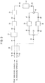
- Fig. 3 shows an exemplary configuration of the refiner 10.
- Fig. 3 illustrates a heat exchanger 30, a cooler 31, a filter 32, a blower 33, an oxygen removal device 34, dehumidifiers 35 and 36, selector valves 46 and 51, and valves 40 to 45, 47 to 50, 52 and 53.
- the oxygen removal device 34 utilizes a palladium catalyst.
- the dehumidifiers 35 and 36 employ a synthetic zeolite catalyst. The two dehumidifiers 35 and 36 are arranged in parallel to allow for continuous operation.
- the steel strip is annealed by being heated to a prescribed temperature (for example, about 800°C) while it is transported through the heating zone 3 and the soaking zone 4, and is thereafter cooled to a prescribed temperature in the cooling zone 5.
- a prescribed temperature for example, about 800°C
- the steel strip is hot dip galvanized by being soaked into the coating bath 7 through the snout 6.
- the coating amount is adjusted to a desired amount with the gas wiping nozzles 8 disposed above the coating bath.
- the steel strip is galvannealed as required with the heating device 9 disposed above the gas wiping nozzles 8.
- an atmosphere gas is supplied into the furnace through the atmosphere gas supply system 15.
- the type, the composition and the method for the supply of the atmosphere gas may be conventional.
- H 2 -N 2 gas is used for an atmosphere gas, and the gas is supplied into the heating zone 3, the soaking zone 4, the cooling zone 5 and subsequent zones in the furnace.
- the atmosphere gas is suctioned from the heating zone 3, the soaking zone 4, and the throat section 14 that is a lower portion of the joint 13 between the soaking zone 4 and the cooling zone 5 through the furnace-to-refiner gas suction openings 22a to 22e.
- the atmosphere gas that has been suctioned is sequentially passed through the heat exchanger 30 and the cooler 31 and thereby the atmosphere gas is cooled to about 40°C or less.
- the atmosphere gas is then cleaned through the filter 32, deoxidized with the oxygen removal device 34, and dehumidified with the dehumidifier 35 or 36, thereby decreasing the dew point to about -60°C. Switching between the dehumidifiers 35 and 36 may be performed by operating the selector valves 46 and 51.
- the gas whose dew point has been decreased is passed through the heat exchanger 30 and is then returned to the heating zone 3 and to the joint 13 between the soaking zone 4 and the cooling zone 5 through the refiner-to-furnace gas ejection openings 23a to 23e.
- the gas having the lowered dew point passes through the heat exchanger 30, and thereby the temperature of the gas to be ejected into the furnace can be increased.
- the gas in the furnace is continuously suctioned through the gas suction opening 22e in the throat section 14 that is a lower portion of the joint 13 between the soaking zone 4 and the cooling zone 5.
- the furnace gas may be suctioned through all of the gas suction openings 22a to 22d disposed in the heating zone 3 and the soaking zone 4 simultaneously, or may be suctioned through any gas suction openings in two or more positions, or may be preferentially suctioned through any one gas suction opening disposed in a high-dew point region that is selected based on the dew point data obtained with the dew point meters.
- the gas ejection to the heating zone 3 is indispensable.
- the gas may be ejected through any one or more of the refiner-to-furnace gas ejection openings 23a to 23d.
- the ejection width W0 of the gas ejection openings preferably satisfies W0/W > 1/4 wherein W is the furnace width of the heating zone plus the soaking zone.
- the atmosphere gas is prevented from stagnating in the upper portion, the middle portion and the lower portion of the furnace in the soaking zone and the former half of the cooling zone and consequently the increase in dew point at the upper portion of the furnace can be prevented.
- the atmosphere gas can be prevented from stagnating in the upper portion, the middle portion and the lower portion of the furnace in the latter half of the heating zone, and the dew point of the atmosphere in the latter half of the heating zone, the soaking zone and the joint between the soaking zone and the cooling zone can be decreased to -45°C or below, or further to -50°C or below.
- the dew point of the gas in the furnace is measured with dew point meters disposed in a plurality of positions, and the gas in the furnace is suctioned preferentially through the suction opening disposed in a position where a higher dew point has been measured. In this manner, the furnace-to-refiner gas flow rate required to obtain the desired dew point may be decreased.
- the line may include a preheating furnace.
- the invention may be applied to a continuous annealing line (CAL) in which a steel strip is continuously annealed.
- CAL continuous annealing line
- inventive configurations allow the furnace atmosphere to stably maintain a low dew point of - 40°C or below where little problems occur in terms of pick-up defects and damages to furnace walls and also at which excellent suppression is possible of the formation of oxides of easily oxidizable elements such as silicon and manganese in the steel that have become concentrated at the surface of steel strips during annealing.
- easy manufacturing becomes possible of steels such as Ti-containing IF steel which do not favor operation in a high-dew point atmosphere.
- a dew point measurement test was carried out in an ART type (all radiant type) CGL illustrated in Fig. 1 (annealing furnace length: 400 m, furnace height in heating zone and soaking zone: 23 m, furnace width in heating zone: 12 m, furnace width in soaking zone: 4 m).
- the furnace had openings through which the atmosphere gas from outside of the furnace is supplied at a total of six locations in the soaking zone, namely, at three locations arranged in the furnace length direction both at 1 m and 10 m above the hearth bottom on the drive side, and at a total of sixteen locations in the heating zone, namely, at eight locations arranged in the furnace length direction both at 1 m and 10 m above the hearth on the drive side.
- the dew point of the atmosphere gas to be supplied was -60°C.
- Furnace-to-refiner gas suction openings and refiner-to-furnace gas ejection openings were disposed as illustrated in Fig. 2 .
- the gas suction openings were disposed in a throat section that was a lower portion of the joint between the soaking zone and the cooling zone, and further at 1 m below the center of upper hearth rolls in the soaking zone, in the center of the soaking zone (at the center of the furnace height and in the middle in the furnace length direction), at 1 m above the center of lower hearth rolls in the soaking zone, and in the center of the heating zone (at the center of the furnace height and in the middle in the furnace length direction), thereby allowing the gas to be suctioned through any of these positions in the heating zone and the soaking zone selected based on the dew point data.
- the refiner-to-furnace gas ejection openings were disposed at a position 1 m away from each of an exit-side furnace wall and a ceiling wall of the joint between the soaking zone and the cooling zone, and at four positions which were 1 m below the center of the upper hearth rolls in the heating zone and were arranged with intervals of 2 m starting from 1 m away from an entrance-side furnace wall.
- the suction openings had a diameter of 200 mm and were paired with a distance therebetween of 1 m except at the joint. A single suction opening was disposed in the joint.
- the diameter of the ejection openings was 50 mm, and a single ejection opening was disposed in the joint and the other four were disposed in the upper portion of the heating zone with intervals of 2 m.
- the distance was 4 m between the ejection opening disposed in the joint between the soaking zone and the cooling zone, and the suction opening disposed in the throat section that was a lower portion of the joint.
- the refiner included dehumidifiers with a synthetic zeolite, and an oxygen removal device with a palladium catalyst.
- Steel strips having a sheet thickness of 0.8 to 1.2 mm and a sheet width of 950 to 1000 mm were tested under as uniform conditions as possible at an annealing temperature of 800°C and a line speed of 100 to 120 mpm.
- the alloy components in the steel strips are described in Table 1.
- the base conditions were divided into four groups A to D by the locations where the highest dew point was measured in the furnace except in the lower portion of the heating zone.
- a dew point of -40°C or below was obtained under all the base conditions.
- a particularly low dew point was obtained when the gas was ejected from the refiner to the inside of the heating zone over a gas ejection width that was larger than 1/4 of the furnace width of the heating zone plus the soaking zone, or when the gas was ejected to the joint between the soaking zone and the cooling zone.
- a low dew point of -50°C or below was obtained when the gas was suctioned to the refiner preferentially from a location where a higher dew point had been measured and also when the gas was ejected from the refiner to the inside of the heating zone over a gas ejection width that was 1/4 or more of the furnace width of the heating zone plus the soaking zone.
- the conditions in a conventional method were such that the atmosphere gas supplied into the furnace had a composition including 8 vol% H 2 and the balance of N 2 and inevitable impurities (dew point -60°C), the rate of gas supply to the cooling zone and subsequent zones was 300 Nm 3 /hr, the rate of gas supply to the soaking zone was 100 Nm 3 /hr, the rate of gas supply to the heating zone was 450 Nm 3 /hr, the steel strips had a sheet thickness of 0.8 to 1.2 mm and a sheet width of 950 to 1000 mm (the alloy components in the steel were the same as in Table 1), the annealing temperature was 800°C, and the line speed was 100 to 120 mpm.
- the conditions in the inventive method were the same as the above conditions and further included the use of the refiner.
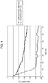
- the initial state of dew point was similar to the base conditions A in EXAMPLE 1 (in which the dew point was highest at the upper portion of the soaking zone). Based on this, the suction performing locations and other configurations were determined in accordance with the conditions of No. 2 (optimum conditions A) in EXAMPLE 1 shown in Table 2. The results of the study are described in Fig. 4 .
- the dew point data indicate the dew point at the upper portion of the soaking zone.
- the inventive method was able to decrease the dew point to -30°C or below in 6 hours, to -40°C or below in 9 hours, and to -50°C or below in 14 hours.
- the continuous annealing furnace for steel strips Prior to the steady operation of continuous heat treatment of a steel strip or when the water concentration and/or the oxygen concentration in the furnace atmosphere has increased during the steady operation, the continuous annealing furnace for steel strips according to the present invention can quickly decrease the water concentration and/or the oxygen concentration in the furnace atmosphere to such a level where the dew point of the furnace atmosphere is lowered to -30°C or below at which stable production of steel strips is feasible.
- a high-strength steel strip containing easily oxidizable elements such as silicon and manganese can be continuously annealed in a way that reduces the problematic occurrence of pick-up defects and damages to furnace walls without any partition wall between the soaking zone and the heating zone.
Landscapes
- Chemical & Material Sciences (AREA)
- Engineering & Computer Science (AREA)
- Mechanical Engineering (AREA)
- Organic Chemistry (AREA)
- Metallurgy (AREA)
- Materials Engineering (AREA)
- Chemical Kinetics & Catalysis (AREA)
- Physics & Mathematics (AREA)
- Thermal Sciences (AREA)
- Crystallography & Structural Chemistry (AREA)
- Oil, Petroleum & Natural Gas (AREA)
- General Engineering & Computer Science (AREA)
- Environmental & Geological Engineering (AREA)
- Heat Treatment Of Strip Materials And Filament Materials (AREA)
- Coating With Molten Metal (AREA)
- Waste-Gas Treatment And Other Accessory Devices For Furnaces (AREA)
Applications Claiming Priority (2)
| Application Number | Priority Date | Filing Date | Title |
|---|---|---|---|
| JP2012006994A JP5505430B2 (ja) | 2012-01-17 | 2012-01-17 | 鋼帯の連続焼鈍炉及び連続焼鈍方法 |
| PCT/JP2013/000192 WO2013108624A1 (ja) | 2012-01-17 | 2013-01-17 | 鋼帯の連続焼鈍炉及び連続焼鈍方法 |
Publications (3)
| Publication Number | Publication Date |
|---|---|
| EP2806043A1 EP2806043A1 (en) | 2014-11-26 |
| EP2806043A4 EP2806043A4 (en) | 2015-06-10 |
| EP2806043B1 true EP2806043B1 (en) | 2018-07-18 |
Family
ID=48799055
Family Applications (1)
| Application Number | Title | Priority Date | Filing Date |
|---|---|---|---|
| EP13738991.2A Active EP2806043B1 (en) | 2012-01-17 | 2013-01-17 | Continuous annealing furnace and continuous annealing method for steel strips |
Country Status (7)
| Country | Link |
|---|---|
| US (1) | US9702020B2 (enExample) |
| EP (1) | EP2806043B1 (enExample) |
| JP (1) | JP5505430B2 (enExample) |
| KR (1) | KR101644730B1 (enExample) |
| CN (2) | CN104053796B (enExample) |
| TW (1) | TWI488975B (enExample) |
| WO (1) | WO2013108624A1 (enExample) |
Families Citing this family (22)
| Publication number | Priority date | Publication date | Assignee | Title |
|---|---|---|---|---|
| JP5982905B2 (ja) | 2012-03-19 | 2016-08-31 | Jfeスチール株式会社 | 高強度溶融亜鉛めっき鋼板の製造方法 |
| CN104204240B (zh) * | 2012-04-06 | 2017-03-08 | 杰富意钢铁株式会社 | 连续式熔融镀锌设备 |
| EP2927342A4 (en) * | 2012-12-04 | 2016-01-06 | Jfe Steel Corp | APPARATUS AND METHOD FOR PRODUCING A CONTINUOUS FIRE-PLATED STEEL PLATE |
| WO2014136412A1 (ja) | 2013-03-04 | 2014-09-12 | Jfeスチール株式会社 | 高強度鋼板及びその製造方法並びに高強度溶融亜鉛めっき鋼板及びその製造方法 |
| JP5790898B1 (ja) * | 2013-11-07 | 2015-10-07 | Jfeスチール株式会社 | 連続焼鈍設備および連続焼鈍方法 |
| CN103555925B (zh) * | 2013-11-08 | 2015-04-22 | 中冶南方(武汉)威仕工业炉有限公司 | 一种用于钛板及钢带退火的立式连续退火炉 |
| FR3014447B1 (fr) * | 2013-12-05 | 2016-02-05 | Fives Stein | Procede et installation de traitement thermique en continu d'une bande d'acier |
| JP5884196B2 (ja) * | 2014-02-18 | 2016-03-15 | Jfeスチール株式会社 | 高強度溶融亜鉛めっき鋼板の製造方法 |
| KR101639155B1 (ko) * | 2015-03-25 | 2016-07-13 | 현대제철 주식회사 | 연속 열처리로의 이슬점 측정 장치 및 그 방법 |
| JP6792561B2 (ja) * | 2015-04-02 | 2020-11-25 | コケリル メンテナンス アンド インジェニエリー ソシエテ アノニム | 反応制御のための方法及び装置 |
| JP6237937B2 (ja) * | 2016-03-11 | 2017-11-29 | Jfeスチール株式会社 | 高強度溶融亜鉛めっき鋼板の製造方法 |
| WO2017182833A1 (en) * | 2016-04-19 | 2017-10-26 | Arcelormittal | Method for producing a metallic coated steel sheet |
| CN109906285B (zh) * | 2016-10-25 | 2021-07-30 | 杰富意钢铁株式会社 | 高强度热镀锌钢板的制造方法 |
| WO2019123953A1 (ja) | 2017-12-22 | 2019-06-27 | Jfeスチール株式会社 | 溶融亜鉛めっき鋼板の製造方法及び連続溶融亜鉛めっき装置 |
| EP3511430A1 (de) * | 2018-01-12 | 2019-07-17 | SMS Group GmbH | Verfahren für eine kontinuierliche wärmebehandlung eines stahlbands, und anlage zum schmelztauchbeschichten eines stahlbands |
| US11713501B2 (en) * | 2019-11-15 | 2023-08-01 | Roteq Machinery Inc. | Machine line and method of annealing multiple individual aluminum and copper wires in tandem with a stranding machine for continuous operation |
| JP2021091960A (ja) * | 2019-12-09 | 2021-06-17 | 中外炉工業株式会社 | 熱処理装置 |
| DE102021201616A1 (de) * | 2020-05-29 | 2021-12-02 | Sms Group Gmbh | Verfahren zum rekristallisierenden Glühen eines nicht-kornorientierten Elektrobandes |
| CN114317942B (zh) * | 2020-09-28 | 2024-05-10 | 上海梅山钢铁股份有限公司 | 一种热镀锌卧式炉炉内漏水判断及处理方法 |
| CN112251698B (zh) * | 2020-11-06 | 2022-11-18 | 河北海洪新材料有限公司 | 一种热镀锌带钢生产余热利用装置 |
| CN112609059A (zh) * | 2020-12-10 | 2021-04-06 | 浙江海亮股份有限公司 | 链式退火炉及管材传送控制方法 |
| IT202200021987A1 (it) * | 2022-10-25 | 2024-04-25 | Danieli Off Mecc | Sistema di rivestimento per rivestire un nastro metallico con uno strato di metallo fuso |
Family Cites Families (20)
| Publication number | Priority date | Publication date | Assignee | Title |
|---|---|---|---|---|
| JPS59133329A (ja) * | 1983-01-19 | 1984-07-31 | Nippon Steel Corp | 連続焼鈍炉における雰囲気ガス置換法 |
| JP2670134B2 (ja) * | 1989-03-08 | 1997-10-29 | 川崎製鉄株式会社 | ステンレス鋼帯の竪型連続光輝焼鈍炉における雰囲気ガス制御方法 |
| JP2567130B2 (ja) | 1990-05-07 | 1996-12-25 | 日本冶金工業株式会社 | 光輝焼鈍炉 |
| JP2567140B2 (ja) | 1990-09-04 | 1996-12-25 | 日本冶金工業株式会社 | 光輝焼鈍炉 |
| JPH0567130A (ja) | 1991-09-09 | 1993-03-19 | Hokkaido Oki Denki Syst:Kk | 承認印付き文書フアイル化装置 |
| JPH0567140A (ja) | 1991-09-09 | 1993-03-19 | Kobe Nippon Denki Software Kk | 機械翻訳装置 |
| JPH08109417A (ja) * | 1994-10-12 | 1996-04-30 | Nippon Steel Corp | 連続焼鈍炉の雰囲気ガス置換法 |
| JP3176843B2 (ja) * | 1996-06-05 | 2001-06-18 | 川崎製鉄株式会社 | 溶融亜鉛めっき鋼板の製造方法および製造設備 |
| JPH09324210A (ja) * | 1996-06-07 | 1997-12-16 | Kawasaki Steel Corp | 溶融亜鉛めっき鋼板の製造方法および製造設備 |
| SE515593C2 (sv) * | 1999-03-01 | 2001-09-03 | Avesta Sheffield Ab | Apparat för värmning av ett metallband |
| JP2000290762A (ja) * | 1999-04-07 | 2000-10-17 | Kawasaki Steel Corp | 溶融めっき鋼板の製造方法 |
| JP2003129125A (ja) * | 2001-10-15 | 2003-05-08 | Daido Steel Co Ltd | ストリップ連続熱処理炉 |
| US7617583B2 (en) * | 2002-09-13 | 2009-11-17 | Jfe Steel Corporation | Method for producing hot-dip coated metal belt |
| JP4192051B2 (ja) * | 2003-08-19 | 2008-12-03 | 新日本製鐵株式会社 | 高強度合金化溶融亜鉛めっき鋼板の製造方法と製造設備 |
| CA2625790C (en) * | 2005-10-14 | 2010-10-12 | Nippon Steel Corporation | Continuous annealing and hot dip plating method and continuous annealing and hot dip plating system of steel sheet containing si |
| CN201809415U (zh) * | 2010-08-31 | 2011-04-27 | 吕军 | 连续退火炉炉内气体清洁度检测装置 |
| JP5071551B2 (ja) * | 2010-12-17 | 2012-11-14 | Jfeスチール株式会社 | 鋼帯の連続焼鈍方法、溶融亜鉛めっき方法 |
| JP5884748B2 (ja) * | 2013-02-25 | 2016-03-15 | Jfeスチール株式会社 | 鋼帯の連続焼鈍装置および連続溶融亜鉛めっき装置 |
| JP5565485B1 (ja) * | 2013-02-25 | 2014-08-06 | Jfeスチール株式会社 | 鋼帯の連続焼鈍装置および連続溶融亜鉛めっき装置 |
| JP5790898B1 (ja) * | 2013-11-07 | 2015-10-07 | Jfeスチール株式会社 | 連続焼鈍設備および連続焼鈍方法 |
-
2012
- 2012-01-17 JP JP2012006994A patent/JP5505430B2/ja active Active
-
2013
- 2013-01-17 CN CN201380005671.0A patent/CN104053796B/zh active Active
- 2013-01-17 EP EP13738991.2A patent/EP2806043B1/en active Active
- 2013-01-17 TW TW102101790A patent/TWI488975B/zh not_active IP Right Cessation
- 2013-01-17 KR KR1020147021987A patent/KR101644730B1/ko active Active
- 2013-01-17 CN CN201610086015.3A patent/CN105671301B/zh active Active
- 2013-01-17 WO PCT/JP2013/000192 patent/WO2013108624A1/ja not_active Ceased
- 2013-01-17 US US14/372,649 patent/US9702020B2/en active Active
Non-Patent Citations (1)
| Title |
|---|
| None * |
Also Published As
| Publication number | Publication date |
|---|---|
| WO2013108624A1 (ja) | 2013-07-25 |
| JP5505430B2 (ja) | 2014-05-28 |
| US9702020B2 (en) | 2017-07-11 |
| TWI488975B (zh) | 2015-06-21 |
| JP2013147681A (ja) | 2013-08-01 |
| EP2806043A1 (en) | 2014-11-26 |
| KR101644730B1 (ko) | 2016-08-01 |
| TW201339318A (zh) | 2013-10-01 |
| CN105671301A (zh) | 2016-06-15 |
| EP2806043A4 (en) | 2015-06-10 |
| CN104053796A (zh) | 2014-09-17 |
| US20150013851A1 (en) | 2015-01-15 |
| CN104053796B (zh) | 2016-03-16 |
| KR20140119104A (ko) | 2014-10-08 |
| CN105671301B (zh) | 2018-01-09 |
Similar Documents
| Publication | Publication Date | Title |
|---|---|---|
| EP2806043B1 (en) | Continuous annealing furnace and continuous annealing method for steel strips | |
| US9163305B2 (en) | Continuous annealing method and a manufacturing method of hot-dip galvanized steel strips | |
| KR101614238B1 (ko) | 강대의 연속 어닐링로, 강대의 연속 어닐링 방법, 연속 용융 아연 도금 설비 및 용융 아연 도금 강대의 제조 방법 | |
| KR101614237B1 (ko) | 강대의 연속 어닐링로, 연속 어닐링 방법, 연속 용융 아연 도금 설비 및 용융 아연 도금 강대의 제조 방법 | |
| EP2862947B1 (en) | Method of continuous annealing of steel strip, and method of manufacturing hot-dip galvanized steel strip |
Legal Events
| Date | Code | Title | Description |
|---|---|---|---|
| PUAI | Public reference made under article 153(3) epc to a published international application that has entered the european phase |
Free format text: ORIGINAL CODE: 0009012 |
|
| 17P | Request for examination filed |
Effective date: 20140811 |
|
| AK | Designated contracting states |
Kind code of ref document: A1 Designated state(s): AL AT BE BG CH CY CZ DE DK EE ES FI FR GB GR HR HU IE IS IT LI LT LU LV MC MK MT NL NO PL PT RO RS SE SI SK SM TR |
|
| DAX | Request for extension of the european patent (deleted) | ||
| RA4 | Supplementary search report drawn up and despatched (corrected) |
Effective date: 20150511 |
|
| RIC1 | Information provided on ipc code assigned before grant |
Ipc: F27B 9/28 20060101ALI20150505BHEP Ipc: C23C 2/40 20060101ALI20150505BHEP Ipc: C23C 2/06 20060101ALI20150505BHEP Ipc: C23C 2/00 20060101ALI20150505BHEP Ipc: C23C 2/02 20060101ALI20150505BHEP Ipc: C23C 2/28 20060101ALI20150505BHEP Ipc: C21D 9/56 20060101AFI20150505BHEP Ipc: F27D 17/00 20060101ALI20150505BHEP Ipc: C21D 9/573 20060101ALI20150505BHEP |
|
| 17Q | First examination report despatched |
Effective date: 20161006 |
|
| STAA | Information on the status of an ep patent application or granted ep patent |
Free format text: STATUS: EXAMINATION IS IN PROGRESS |
|
| GRAP | Despatch of communication of intention to grant a patent |
Free format text: ORIGINAL CODE: EPIDOSNIGR1 |
|
| STAA | Information on the status of an ep patent application or granted ep patent |
Free format text: STATUS: GRANT OF PATENT IS INTENDED |
|
| INTG | Intention to grant announced |
Effective date: 20180305 |
|
| GRAS | Grant fee paid |
Free format text: ORIGINAL CODE: EPIDOSNIGR3 |
|
| GRAA | (expected) grant |
Free format text: ORIGINAL CODE: 0009210 |
|
| STAA | Information on the status of an ep patent application or granted ep patent |
Free format text: STATUS: THE PATENT HAS BEEN GRANTED |
|
| AK | Designated contracting states |
Kind code of ref document: B1 Designated state(s): AL AT BE BG CH CY CZ DE DK EE ES FI FR GB GR HR HU IE IS IT LI LT LU LV MC MK MT NL NO PL PT RO RS SE SI SK SM TR |
|
| REG | Reference to a national code |
Ref country code: GB Ref legal event code: FG4D |
|
| REG | Reference to a national code |
Ref country code: CH Ref legal event code: EP |
|
| REG | Reference to a national code |
Ref country code: IE Ref legal event code: FG4D |
|
| REG | Reference to a national code |
Ref country code: AT Ref legal event code: REF Ref document number: 1019428 Country of ref document: AT Kind code of ref document: T Effective date: 20180815 |
|
| REG | Reference to a national code |
Ref country code: DE Ref legal event code: R096 Ref document number: 602013040469 Country of ref document: DE |
|
| REG | Reference to a national code |
Ref country code: NL Ref legal event code: MP Effective date: 20180718 |
|
| REG | Reference to a national code |
Ref country code: LT Ref legal event code: MG4D |
|
| REG | Reference to a national code |
Ref country code: AT Ref legal event code: MK05 Ref document number: 1019428 Country of ref document: AT Kind code of ref document: T Effective date: 20180718 |
|
| PG25 | Lapsed in a contracting state [announced via postgrant information from national office to epo] |
Ref country code: NL Free format text: LAPSE BECAUSE OF FAILURE TO SUBMIT A TRANSLATION OF THE DESCRIPTION OR TO PAY THE FEE WITHIN THE PRESCRIBED TIME-LIMIT Effective date: 20180718 |
|
| PG25 | Lapsed in a contracting state [announced via postgrant information from national office to epo] |
Ref country code: LT Free format text: LAPSE BECAUSE OF FAILURE TO SUBMIT A TRANSLATION OF THE DESCRIPTION OR TO PAY THE FEE WITHIN THE PRESCRIBED TIME-LIMIT Effective date: 20180718 Ref country code: PL Free format text: LAPSE BECAUSE OF FAILURE TO SUBMIT A TRANSLATION OF THE DESCRIPTION OR TO PAY THE FEE WITHIN THE PRESCRIBED TIME-LIMIT Effective date: 20180718 Ref country code: FI Free format text: LAPSE BECAUSE OF FAILURE TO SUBMIT A TRANSLATION OF THE DESCRIPTION OR TO PAY THE FEE WITHIN THE PRESCRIBED TIME-LIMIT Effective date: 20180718 Ref country code: GR Free format text: LAPSE BECAUSE OF FAILURE TO SUBMIT A TRANSLATION OF THE DESCRIPTION OR TO PAY THE FEE WITHIN THE PRESCRIBED TIME-LIMIT Effective date: 20181019 Ref country code: IS Free format text: LAPSE BECAUSE OF FAILURE TO SUBMIT A TRANSLATION OF THE DESCRIPTION OR TO PAY THE FEE WITHIN THE PRESCRIBED TIME-LIMIT Effective date: 20181118 Ref country code: RS Free format text: LAPSE BECAUSE OF FAILURE TO SUBMIT A TRANSLATION OF THE DESCRIPTION OR TO PAY THE FEE WITHIN THE PRESCRIBED TIME-LIMIT Effective date: 20180718 Ref country code: AT Free format text: LAPSE BECAUSE OF FAILURE TO SUBMIT A TRANSLATION OF THE DESCRIPTION OR TO PAY THE FEE WITHIN THE PRESCRIBED TIME-LIMIT Effective date: 20180718 Ref country code: SE Free format text: LAPSE BECAUSE OF FAILURE TO SUBMIT A TRANSLATION OF THE DESCRIPTION OR TO PAY THE FEE WITHIN THE PRESCRIBED TIME-LIMIT Effective date: 20180718 Ref country code: BG Free format text: LAPSE BECAUSE OF FAILURE TO SUBMIT A TRANSLATION OF THE DESCRIPTION OR TO PAY THE FEE WITHIN THE PRESCRIBED TIME-LIMIT Effective date: 20181018 Ref country code: NO Free format text: LAPSE BECAUSE OF FAILURE TO SUBMIT A TRANSLATION OF THE DESCRIPTION OR TO PAY THE FEE WITHIN THE PRESCRIBED TIME-LIMIT Effective date: 20181018 |
|
| PG25 | Lapsed in a contracting state [announced via postgrant information from national office to epo] |
Ref country code: LV Free format text: LAPSE BECAUSE OF FAILURE TO SUBMIT A TRANSLATION OF THE DESCRIPTION OR TO PAY THE FEE WITHIN THE PRESCRIBED TIME-LIMIT Effective date: 20180718 Ref country code: AL Free format text: LAPSE BECAUSE OF FAILURE TO SUBMIT A TRANSLATION OF THE DESCRIPTION OR TO PAY THE FEE WITHIN THE PRESCRIBED TIME-LIMIT Effective date: 20180718 Ref country code: HR Free format text: LAPSE BECAUSE OF FAILURE TO SUBMIT A TRANSLATION OF THE DESCRIPTION OR TO PAY THE FEE WITHIN THE PRESCRIBED TIME-LIMIT Effective date: 20180718 |
|
| REG | Reference to a national code |
Ref country code: DE Ref legal event code: R097 Ref document number: 602013040469 Country of ref document: DE |
|
| PG25 | Lapsed in a contracting state [announced via postgrant information from national office to epo] |
Ref country code: IT Free format text: LAPSE BECAUSE OF FAILURE TO SUBMIT A TRANSLATION OF THE DESCRIPTION OR TO PAY THE FEE WITHIN THE PRESCRIBED TIME-LIMIT Effective date: 20180718 Ref country code: ES Free format text: LAPSE BECAUSE OF FAILURE TO SUBMIT A TRANSLATION OF THE DESCRIPTION OR TO PAY THE FEE WITHIN THE PRESCRIBED TIME-LIMIT Effective date: 20180718 Ref country code: CZ Free format text: LAPSE BECAUSE OF FAILURE TO SUBMIT A TRANSLATION OF THE DESCRIPTION OR TO PAY THE FEE WITHIN THE PRESCRIBED TIME-LIMIT Effective date: 20180718 Ref country code: RO Free format text: LAPSE BECAUSE OF FAILURE TO SUBMIT A TRANSLATION OF THE DESCRIPTION OR TO PAY THE FEE WITHIN THE PRESCRIBED TIME-LIMIT Effective date: 20180718 Ref country code: EE Free format text: LAPSE BECAUSE OF FAILURE TO SUBMIT A TRANSLATION OF THE DESCRIPTION OR TO PAY THE FEE WITHIN THE PRESCRIBED TIME-LIMIT Effective date: 20180718 |
|
| PLBE | No opposition filed within time limit |
Free format text: ORIGINAL CODE: 0009261 |
|
| STAA | Information on the status of an ep patent application or granted ep patent |
Free format text: STATUS: NO OPPOSITION FILED WITHIN TIME LIMIT |
|
| PG25 | Lapsed in a contracting state [announced via postgrant information from national office to epo] |
Ref country code: DK Free format text: LAPSE BECAUSE OF FAILURE TO SUBMIT A TRANSLATION OF THE DESCRIPTION OR TO PAY THE FEE WITHIN THE PRESCRIBED TIME-LIMIT Effective date: 20180718 Ref country code: SM Free format text: LAPSE BECAUSE OF FAILURE TO SUBMIT A TRANSLATION OF THE DESCRIPTION OR TO PAY THE FEE WITHIN THE PRESCRIBED TIME-LIMIT Effective date: 20180718 Ref country code: SK Free format text: LAPSE BECAUSE OF FAILURE TO SUBMIT A TRANSLATION OF THE DESCRIPTION OR TO PAY THE FEE WITHIN THE PRESCRIBED TIME-LIMIT Effective date: 20180718 |
|
| 26N | No opposition filed |
Effective date: 20190423 |
|
| PG25 | Lapsed in a contracting state [announced via postgrant information from national office to epo] |
Ref country code: SI Free format text: LAPSE BECAUSE OF FAILURE TO SUBMIT A TRANSLATION OF THE DESCRIPTION OR TO PAY THE FEE WITHIN THE PRESCRIBED TIME-LIMIT Effective date: 20180718 Ref country code: MC Free format text: LAPSE BECAUSE OF FAILURE TO SUBMIT A TRANSLATION OF THE DESCRIPTION OR TO PAY THE FEE WITHIN THE PRESCRIBED TIME-LIMIT Effective date: 20180718 |
|
| REG | Reference to a national code |
Ref country code: CH Ref legal event code: PL |
|
| PG25 | Lapsed in a contracting state [announced via postgrant information from national office to epo] |
Ref country code: LU Free format text: LAPSE BECAUSE OF NON-PAYMENT OF DUE FEES Effective date: 20190117 |
|
| REG | Reference to a national code |
Ref country code: BE Ref legal event code: MM Effective date: 20190131 |
|
| REG | Reference to a national code |
Ref country code: IE Ref legal event code: MM4A |
|
| PG25 | Lapsed in a contracting state [announced via postgrant information from national office to epo] |
Ref country code: BE Free format text: LAPSE BECAUSE OF NON-PAYMENT OF DUE FEES Effective date: 20190131 |
|
| PG25 | Lapsed in a contracting state [announced via postgrant information from national office to epo] |
Ref country code: LI Free format text: LAPSE BECAUSE OF NON-PAYMENT OF DUE FEES Effective date: 20190131 Ref country code: CH Free format text: LAPSE BECAUSE OF NON-PAYMENT OF DUE FEES Effective date: 20190131 |
|
| PG25 | Lapsed in a contracting state [announced via postgrant information from national office to epo] |
Ref country code: IE Free format text: LAPSE BECAUSE OF NON-PAYMENT OF DUE FEES Effective date: 20190117 |
|
| PG25 | Lapsed in a contracting state [announced via postgrant information from national office to epo] |
Ref country code: TR Free format text: LAPSE BECAUSE OF FAILURE TO SUBMIT A TRANSLATION OF THE DESCRIPTION OR TO PAY THE FEE WITHIN THE PRESCRIBED TIME-LIMIT Effective date: 20180718 |
|
| PGFP | Annual fee paid to national office [announced via postgrant information from national office to epo] |
Ref country code: GB Payment date: 20200113 Year of fee payment: 8 |
|
| PG25 | Lapsed in a contracting state [announced via postgrant information from national office to epo] |
Ref country code: MT Free format text: LAPSE BECAUSE OF NON-PAYMENT OF DUE FEES Effective date: 20190117 Ref country code: PT Free format text: LAPSE BECAUSE OF FAILURE TO SUBMIT A TRANSLATION OF THE DESCRIPTION OR TO PAY THE FEE WITHIN THE PRESCRIBED TIME-LIMIT Effective date: 20181118 |
|
| PG25 | Lapsed in a contracting state [announced via postgrant information from national office to epo] |
Ref country code: CY Free format text: LAPSE BECAUSE OF FAILURE TO SUBMIT A TRANSLATION OF THE DESCRIPTION OR TO PAY THE FEE WITHIN THE PRESCRIBED TIME-LIMIT Effective date: 20180718 |
|
| PG25 | Lapsed in a contracting state [announced via postgrant information from national office to epo] |
Ref country code: HU Free format text: LAPSE BECAUSE OF FAILURE TO SUBMIT A TRANSLATION OF THE DESCRIPTION OR TO PAY THE FEE WITHIN THE PRESCRIBED TIME-LIMIT; INVALID AB INITIO Effective date: 20130117 |
|
| GBPC | Gb: european patent ceased through non-payment of renewal fee |
Effective date: 20210117 |
|
| PG25 | Lapsed in a contracting state [announced via postgrant information from national office to epo] |
Ref country code: GB Free format text: LAPSE BECAUSE OF NON-PAYMENT OF DUE FEES Effective date: 20210117 |
|
| PGFP | Annual fee paid to national office [announced via postgrant information from national office to epo] |
Ref country code: FR Payment date: 20211217 Year of fee payment: 10 |
|
| PG25 | Lapsed in a contracting state [announced via postgrant information from national office to epo] |
Ref country code: MK Free format text: LAPSE BECAUSE OF FAILURE TO SUBMIT A TRANSLATION OF THE DESCRIPTION OR TO PAY THE FEE WITHIN THE PRESCRIBED TIME-LIMIT Effective date: 20180718 |
|
| PG25 | Lapsed in a contracting state [announced via postgrant information from national office to epo] |
Ref country code: FR Free format text: LAPSE BECAUSE OF NON-PAYMENT OF DUE FEES Effective date: 20230131 |
|
| PGFP | Annual fee paid to national office [announced via postgrant information from national office to epo] |
Ref country code: DE Payment date: 20241203 Year of fee payment: 13 |