EP2804770B1 - Verschleissarme reifenlauffläche - Google Patents
Verschleissarme reifenlauffläche Download PDFInfo
- Publication number
- EP2804770B1 EP2804770B1 EP13710547.4A EP13710547A EP2804770B1 EP 2804770 B1 EP2804770 B1 EP 2804770B1 EP 13710547 A EP13710547 A EP 13710547A EP 2804770 B1 EP2804770 B1 EP 2804770B1
- Authority
- EP
- European Patent Office
- Prior art keywords
- arc
- tread band
- radius
- junction
- tread
- Prior art date
- Legal status (The legal status is an assumption and is not a legal conclusion. Google has not performed a legal analysis and makes no representation as to the accuracy of the status listed.)
- Active
Links
- 230000007704 transition Effects 0.000 claims description 3
- 238000005096 rolling process Methods 0.000 description 10
- 230000008901 benefit Effects 0.000 description 7
- XLYOFNOQVPJJNP-UHFFFAOYSA-N water Substances O XLYOFNOQVPJJNP-UHFFFAOYSA-N 0.000 description 4
- 150000001875 compounds Chemical class 0.000 description 3
- 210000005069 ears Anatomy 0.000 description 3
- 230000001788 irregular Effects 0.000 description 3
- 238000010926 purge Methods 0.000 description 3
- 239000011324 bead Substances 0.000 description 2
- 239000000463 material Substances 0.000 description 1
- 239000007787 solid Substances 0.000 description 1
Images


Classifications
-
- B—PERFORMING OPERATIONS; TRANSPORTING
- B60—VEHICLES IN GENERAL
- B60C—VEHICLE TYRES; TYRE INFLATION; TYRE CHANGING; CONNECTING VALVES TO INFLATABLE ELASTIC BODIES IN GENERAL; DEVICES OR ARRANGEMENTS RELATED TO TYRES
- B60C11/00—Tyre tread bands; Tread patterns; Anti-skid inserts
- B60C11/0083—Tyre tread bands; Tread patterns; Anti-skid inserts characterised by the curvature of the tyre tread
-
- A—HUMAN NECESSITIES
- A61—MEDICAL OR VETERINARY SCIENCE; HYGIENE
- A61H—PHYSICAL THERAPY APPARATUS, e.g. DEVICES FOR LOCATING OR STIMULATING REFLEX POINTS IN THE BODY; ARTIFICIAL RESPIRATION; MASSAGE; BATHING DEVICES FOR SPECIAL THERAPEUTIC OR HYGIENIC PURPOSES OR SPECIFIC PARTS OF THE BODY
- A61H3/00—Appliances for aiding patients or disabled persons to walk about
- A61H3/008—Appliances for aiding patients or disabled persons to walk about using suspension devices for supporting the body in an upright walking or standing position, e.g. harnesses
-
- B—PERFORMING OPERATIONS; TRANSPORTING
- B60—VEHICLES IN GENERAL
- B60C—VEHICLE TYRES; TYRE INFLATION; TYRE CHANGING; CONNECTING VALVES TO INFLATABLE ELASTIC BODIES IN GENERAL; DEVICES OR ARRANGEMENTS RELATED TO TYRES
- B60C11/00—Tyre tread bands; Tread patterns; Anti-skid inserts
- B60C11/03—Tread patterns
- B60C11/0304—Asymmetric patterns
-
- B—PERFORMING OPERATIONS; TRANSPORTING
- B60—VEHICLES IN GENERAL
- B60C—VEHICLE TYRES; TYRE INFLATION; TYRE CHANGING; CONNECTING VALVES TO INFLATABLE ELASTIC BODIES IN GENERAL; DEVICES OR ARRANGEMENTS RELATED TO TYRES
- B60C11/00—Tyre tread bands; Tread patterns; Anti-skid inserts
- B60C11/03—Tread patterns
- B60C11/0327—Tread patterns characterised by special properties of the tread pattern
- B60C11/0332—Tread patterns characterised by special properties of the tread pattern by the footprint-ground contacting area of the tyre tread
-
- B—PERFORMING OPERATIONS; TRANSPORTING
- B60—VEHICLES IN GENERAL
- B60C—VEHICLE TYRES; TYRE INFLATION; TYRE CHANGING; CONNECTING VALVES TO INFLATABLE ELASTIC BODIES IN GENERAL; DEVICES OR ARRANGEMENTS RELATED TO TYRES
- B60C11/00—Tyre tread bands; Tread patterns; Anti-skid inserts
- B60C11/01—Shape of the shoulders between tread and sidewall, e.g. rounded, stepped or cantilevered
- B60C2011/013—Shape of the shoulders between tread and sidewall, e.g. rounded, stepped or cantilevered provided with a recessed portion
Definitions
- the present invention relates to a tyre tread band.
- One known way of improving tyre tread wear is to use special rubber compounds for the tread.
- Low-wear tread compounds have the drawback of poor wet-road-holding performance (in other words, the improvement in wear achieved by altering the compound from which the tread is made is normally counterbalanced by a reduction in wet-road-holding performance).
- Another known way of improving tyre tread wear is to reduce the voids in favour of solids in the tread pattern, to increase the rubber-on-pavement contact area of the footprint (and so reduce the specific pressure, and therefore mechanical stress, on the tread for a given vertical load on the tyre).
- This solution further reduces wet-road-holding performance by impairing water purging from the footprint.
- Patent Application EP878329A1 describes a tyre tread band comprising a centre; two shoulders on either side of the centre; and two edges on either side of the shoulders and forming a transition with the sidewalls.
- the tread band profile comprises a first arc having a first radius R'; and two second arcs located outwards of the first arc and having a second radius Rs' smaller than the first radius R'.
- each second arc is connected continuously (i.e. with no discontinuity) to the first arc; and the radial distance To', Tt' between the extension of the first arc and the second arc increases gradually from the centre towards the shoulders.
- the tread band profile comprises a first arc having a radius R'; and two second arcs located outwards of the first arc and having the same radius R'.
- each second arc is connected discontinuously to the first arc, forming a step, wherein the second arc is not tangent to, and is radially lower than, the first arc; and the radial distance To', Tt' between the extension of the first arc and the second arc is constant from the centre towards the shoulders.
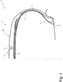
- Number 1 in Figure 1 indicates as a whole a tyre mounted on a rim 2 (shown partly and schematically).
- Tyre 1 comprises a toroidal body ply 3 having two beads 4 and supporting a tread band 5 made of cured-rubber-based material.
- a tread belt 6 is interposed between body ply 3 and tread band 5.
- body ply 3 supports two sidewalls 7 between tread band 5 and beads 4.
- Tread band 5 has a rolling surface 8, which externally defines tread band 5 (i.e. is located radially outwards) and, in use, rests on the road surface.
- Rolling surface 8 of tread band 5 is interrupted by a raised pattern bounded by a number of longitudinal or transverse grooves 9, which define a number of blocks projecting radially from tread band 5.
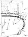
- tread band 5 extends between two opposite lateral ends E (only one shown in Figure 2 ) located at the borders between tread band 5 and sidewalls 7. Dividing tread band 5 into two symmetrical halves, each half (as shown in Figure 2 ) extends between a centre point C, located at the longitudinal (circumferential) plane of symmetry, and a lateral end E.
- the profile of each half of tread band 5 (as shown in Figure 2 ) comprises five successive arcs A1-A5 with respective radii CR1-CR5 (which decrease gradually from the centre to the periphery).
- Arc A1 has a radius CR1, has a centre along the longitudinal (circumferential) plane of symmetry, is located at the centreline of tread band 5, and extends (in each half of tread band 5) to a length L1.
- Arc A2 is located alongside arc A1, is connected to arc A1 at a junction J12, has a radius CR2 smaller than radius CR1 of arc A1, and extends to a length L2-L1.
- Arc A3 is located alongside arc A2, is connected to arc A2 at a junction J23, has a radius CR3 smaller than radius CR2 of arc A2, and extends to a length L3-L2.
- Arc A4 is located alongside arc A3, is connected to arc A3 at a junction J34, has a radius CR4 smaller than radius CR3 of arc A3, and extends to a length L4-L3.
- arc A5 is located alongside arc A4, is connected to arc A4 at a junction J45, has a radius CR5 smaller than radius CR4 of arc A4, and extends to a length L5-L4.
- length L1 of arc A1 (in each half of tread band 5) is greater than the length (L2-L1) of arc A2. That is: L 1 > L 2 ⁇ L 1
- Arcs A1 and A2 form part of the centre of tread band 5; arc A3 forms part of the shoulder of tread band 5; and arcs A4 and A5 form part of the edge of tread band 5, which does not normally come into contact with the road surface as tyre 1 rolls, and which forms a transition between tread band 5 and the corresponding sidewall 7.
- arc A2 is eliminated, and arc A1 is connected directly to arc A3 (i.e. arcs A1 and A2 coincide).
- arc A5 is eliminated, and arc A4 is connected directly to sidewall 7 (i.e. arcs A4 and A5 coincide).
- junction J12 arc A2 is tangent to arc A1, so as to connect arcs A1 and A2 continuously.
- arc A4 is tangent to arc A3, so as to connect arcs A3 and A4 continuously.
- arc A5 is tangent to arc A4, so as to connect arcs A4 and A5 continuously.
- junction J23 arc A3 is not tangent to arc A2, and is radially lower than arc A2, so as to connect arcs A2 and A3 discontinuously by a step.
- junction J23 is located at a longitudinal groove 9, which means there is no 'connection' between arcs A2 and A3.
- arcs A2 and A3 are 'connected' at junction J23 by an S-shaped fillet, i.e. having two oppositely-concave curves (one concave and one convex) with respective radii FR1 and FR2.
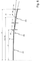
- the height H1 of the step i.e. the radial distance between the end of arc A2 and the end of arc A3, i.e. the radial distance between arcs A2 and A3 ranges between 0.05% and 0.15% of the total diameter OD of tyre 1, i.e. 0.0005 * OD ⁇ H 1 ⁇ 0.0015 * OD
- the height H1 of the discontinuity step may be roughly 0.3 to 1.2 mm.
- the ratio between length L2 between the longitudinal (circumferential) plane of symmetry and junction J23 and the reference tread width TW ranges between 0.8 and 1.4, i.e. 0.80 ⁇ L 2 / TW ⁇ 1.40
- the ratio between length L2 between the longitudinal (circumferential) plane of symmetry and junction J23 and the reference tread width TW ranges between 1.0 and 1.2, i.e. 1.00 ⁇ L 2 / TW ⁇ 1.20
- tread band 5 footprint 'shape' which provides for excellent wear resistance and wet-road-holding performance, and low noise.
- the tread band 5 footprint is of 'regular' shape, as shown in Figures 7 to 9 (i.e.
- the tread band 5 footprint is 'irregular' in shape (as shown in Figure 10 ) with a larger central area and two smaller lateral areas ('ears').
- a rectangular footprint of tread band 5 (as shown in Figure 9 ) has excellent wear resistance, but impairs wet-road-holding performance and increases noise; an elliptical footprint of tread band 5 (as shown in Figure 7 ) provides for excellent wet-road-holding performance and low noise, but impairs wear resistance; an intermediate footprint of tread band 5 (as shown in Figure 8 ) is a classic trade-off, which attempts to balance wear resistance with wet-road-holding performance and low noise, but excels in none of them; whereas, an 'irregular' footprint of tread band 5 (as shown in Figure 10 ), which is only achievable in accordance with the present invention, achieves only the advantages, and none of the drawbacks, of the others, i.e. excellent wear resistance and wet-road-holding performance, and low noise.
- the key to achieving the 'irregular' footprint shape of tread band 5 is the discontinuity at junction J23, i.e. the step, at junction J23, between the (radially higher) end of arc A2 and the (radially lower) end of arc A3.
- the discontinuity at junction J23 i.e. the step, at junction J23, between the (radially higher) end of arc A2 and the (radially lower) end of arc A3.
- other factors also govern the shape of the tread band 5 profile at junction J23.
- Varying the position of discontinuous junction J23 alters the ratio between the larger central area and the two smaller lateral areas or 'ears' of the footprint.
- the relationship described above between length L2 between the longitudinal (circumferential) plane of symmetry and junction J23 and reference tread width TW therefore ensures an optimum 'shape' of the tread band 5 footprint.
- the total width of the tread band 5 footprint ranges between 80% and 90% of reference tread width TW.
- reference tread width TW is the distance between the two points of intersection I (only one shown in Figures 2 and 5 ) on either side of tread band 5; and, on each side of tread band 5, the point of intersection I is the point at which the extensions of arcs A3 and A5 intersect (i.e. the point at which the outward extension of arc A3 intersects the inward extension of arc A5).
- the radial distance H between the extension of arc A2 and arc A3 must increase gradually from the centre towards the shoulders. Consequently, the radial distance H1 between the extension of arc A2 and arc A3 (i.e. the height H1 of the step) at junction J23 must be less than the radial distance H2 between the extension of arc A2 and arc A3 at junction J34.
- junction J23 makes for a much shorter contact length of the shoulders than of the centre of tread band 5, which benefits both wet-road-holding performance (by greatly increasing maximum hydroplaning speed and so improving water purge from the centre towards the shoulders) and rolling noise (due to the different impact-release times of the shoulder blocks with respect to the centre blocks of tread band 5).
- junction J23 enables use of arcs A1-A3 with very long radii CR1-CR3, which enables tread band 5 to flatten easily on the road surface as the tyre rolls, thus distributing contact evenly over the whole of tread band 5.
- the differences in the rolling radius along tread band 5 are negligible, thus minimizing longitudinal slide, which produces greater local wear.
- the Figure 7 footprint has a roughly 70% FR ratio (i.e. the ratio between the contact length of the shoulders and the contact length of the centre of tread band 5); the Figure 8 footprint has a roughly 80% FR ratio; and the Figure 9 footprint has a roughly 99% FR ratio.
- the Figure 10 footprint has a roughly 65% FR ratio, which provides for achieving the same wet-road-holding performance and noise level as the Figure 7 footprint, but also a wear resistance better than that of the Figure 8 footprint and almost the same as (only slightly less than) that of the Figure 9 footprint.
- step heights H1 at junction J23 are sufficient to achieve 60-70% FR ratios.
- Smaller FR ratios could be obtained by increasing height H1, but are not recommended, on the grounds that they provide for no significant improvement in wet-road-holding performance or noise level, while at the same time greatly impairing wear resistance.
- arc A1 has a very large radius CR1 (more specifically, radius CR1 of arc A1 may even be infinite, in which case, arc A1 degenerates into a segment).
- radius CR1 of arc A1 is over 600-1500 mm (600 mm for small tyres, and 1500 mm for large tyres).
- radius CR1 of arc A1 is over twice the total diameter OD of tyre 1.
- the centre of tread band 5 is therefore substantially flat, which enables tread band 5 to flatten easily on the road surface as the tyre rolls, thus distributing contact evenly over the whole of tread band 5.
- Another advantage lies in the contact length at the centre of tread band 5 also being distributed evenly. As such, the differences in the rolling radius along the centre of tread band 5 are negligible, thus minimizing longitudinal slide, which produces greater local wear.
- Radius CR3 of arc A3 of each shoulder of tread band 5 is smaller than radii CR1 and CR2 of arcs A1 and A2 of the centre of tread band 5, and must be long enough to reduce deformation and longitudinal slide of the shoulder of tread band 5 contacting the road surface. Unlike radii CR1 and CR2 of arcs A1 and A2 of the centre of tread band 5, however, radius CR3 of arc A3 of each shoulder of tread band 5 must not be too long to connect with radius CR4 of arc A4 of the edge of tread band 5, which is relatively small to connect to sidewalls 7.
- radius CR3 of arc A3 and radius CR4 of arc A4 would result in a concentration of stresses, and therefore severe wear, at the edge of tread band 5.
- radius CR3 of arc A3 As the shoulders of tread band 5 contact the road surface, concave deformation changes their curvature from convex to flat; so, if the undeformed shoulders of tread band 5 were to be already flat (or almost) due to very long radii CR3, concave deformation would cause the shoulders of tread band 5 to assume a concave shape, thus resulting in concentrated stresses and wear on both the inner and outer side of each shoulder.
- radius CR3 of arc A3 must preferably range between 80 mm (for small tyres) and 400 mm (for larger tyres); and radius CR4 of arc A4 normally ranges between roughly 20 mm and 35 mm.
- the shoulder slope angle ⁇ (shown in Figure 5 ), which is the angle between the tangent SL to arc A3 at the characteristic point SP, and the horizontal.
- the characteristic point SP at which the tangent SL to arc A3 is determined, is the point along arc A3 separated from the longitudinal (circumferential) plane of symmetry by a distance equal to 40% of reference tread width TW.
- the shoulder slope angle ⁇ must not be too small (close to zero), to avoid impairing water purge (with small shoulder slope angles ⁇ , water accumulates in the shoulders, impairing wet-road-holding performance), and to avoid increasing wear on the outer edges of the shoulders.
- the shoulder slope angle ⁇ preferably ranges between 5° and 20°, and more preferably between 8° and 12°, which makes it easier to achieve the condition in which the radial distance H between the extension of arc A2 and arc A3 increases gradually from the centre towards the shoulders, i.e. in which the radial distance H1 between the extension of arc A2 and arc A3 (i.e. the height H1 of the step) at junction J23 is less than the radial distance H2 between the extension of arc A2 and arc A3 at junction J34.
- Discontinuous step junction J23 also has the further advantage of further improving wear resistance.
- the vertical load is transmitted mostly by the pressurized air inside tyre 1, and to a lesser degree by the structure of tyre 1.
- the shoulders of tread band 5, as they 'roll' on their curved profile tend to lift up the centre of tread band 5, thus reducing pressure in the centre and increasing pressure (and hence wear) on the shoulders.
- tread band 5 is symmetrical (i.e. specular with respect to the longitudinal plane of symmetry of tyre 1).
- tread band 5 may be asymmetrical (i.e. not specular with respect to the longitudinal plane of symmetry of tyre 1).
- Tread band 5 described has numerous advantages.
Landscapes
- Mechanical Engineering (AREA)
- Engineering & Computer Science (AREA)
- Health & Medical Sciences (AREA)
- Animal Behavior & Ethology (AREA)
- Rehabilitation Therapy (AREA)
- Life Sciences & Earth Sciences (AREA)
- Physical Education & Sports Medicine (AREA)
- General Health & Medical Sciences (AREA)
- Public Health (AREA)
- Veterinary Medicine (AREA)
- Pain & Pain Management (AREA)
- Epidemiology (AREA)
- Tires In General (AREA)
- Rehabilitation Tools (AREA)
Claims (14)
- Reifenlauffläche (5) für einen Reifen (1):die Reifenlauffläche (5) umfasst eine Mitte; zwei Schultern auf jeder Seite der Mitte; und zwei Kanten an jeder Seite der Schultern und einen Übergang mit den Seitenwänden (7) bildend;das Profil der Reifenlauffläche (5) umfasst zumindest einen ersten Bogen (A2), der einen Teil der Mitte der Reifenlauffläche (5) bildet und einen ersten Radius (CR2) aufweist; zwei zweite Bögen (A3), die einen Teil der Schultern der Reifenlauffläche (5) bilden und einen zweiten Radius (CR3) aufweisen; und zwei dritte Bögen (A4), die einen Teil der Kanten der Reifenlauffläche (5) bilden und einen dritten Radius (CR4) aufweisen;an einem ersten Übergang (J23) ist jeder zweite Bogen (A3) diskontinuierlich mit dem ersten Bogen (A2) durch eine Stufe verbunden, wobei der zweite Bogen (A3) nicht dazu tangential ist und radial kleiner ist als der erste Bogen (A2); und an einem zweiten Übergang (J34) ist jeder dritte Bogen (A4) tangential und kontinuierlich mit dem zweiten Bogen (A3) verbunden;die Reifenlauffläche (5) dadurch gekennzeichnet, dass der radiale Abstand (H) zwischen der Ausdehnung des ersten Bogens (A2) und des zweiten Bogens (A3) sich graduell von der Mitte zu den Schultern vergrößert, so dass der radiale Abstand (H1), der an dem ersten Übergang (J23) gemessen wird, zwischen der Ausdehnung des ersten Bogens (A2) und des zweiten Bogens (A3) geringer ist als der radiale Abstand (H2), der an dem zweiten Übergang (J34) gemessen wird, zwischen der Ausdehnung des ersten Bogens (A2) und des zweiten Bogens (A3).
- Reifenlauffläche (5) nach Anspruch 1, wobei der erste Radius (CR2) des ersten Bogens (A2) größer ist als der zweite Radius (CR3) des zweiten Bogens (A3), welcher wiederum größer ist als der dritte Radius (CR4) des dritten Bogens (A4).
- Reifenlauffläche (5) nach Anspruch 1 oder 2, wobei:das Profil der Reifenlauffläche (5) auch einen vierten Bogen (A1) umfasst, welcher einen vierten Radius (CR1) aufweist, der größer ist als der erste Radius (CR2) des ersten Bogens (A2), welcher Teil der Mitte der Reifenlauffläche (5) ist und zentral zwischen den zwei ersten Bögen (A2) gelegen ist; undan einem dritten Übergang (J12) jeder erste Bogen (A2) tangential und kontinuierlich mit dem vierten Bogen (A1) verbunden ist.
- Reifenlauffläche (5) nach Anspruch 3, wobei der vierte Radius (CR1) des vierten Bogens (A1) über 600 mm ist.
- Reifenlauffläche (5) nach Anspruch 3, wobei der vierte Radius (CR1) des vierten Bogens (A1) mehr zweimal der gesamte Durchmesser (OD) des Reifens (1) ist.
- Reifenlauffläche (5) nach einem der Ansprüche 3, 4 oder 5, wobei die Länge (L1) des vierten Bogens (A1) in einer Hälfte der Reifenlauffläche (5) größer ist als die Länge (L2-L1) des ersten Bogens (A2).
- Reifenlauffläche (5) nach einem der Ansprüche 1 bis 6, wobei der zweite Radius (CR3) des zweiten Bogens (A3) zwischen 80 mm und 400 mm liegt.
- Reifenlauffläche (5) nach einem der Ansprüche 1 bis 7, wobei:das Profil der Reifenlauffläche (5) auch zwei fünfte Bögen (A5) umfasst, welche einen fünften Radius (CR5) aufweisen, welche Teil der Kanten der Reifenlauffläche (5) bilden und an jeder Seite der dritten Bögen (A4) gelegen sind; undan einem vierten Übergang (J45) jeder dritte Bogen (A4) tangential und kontinuierlich mit dem fünften Bogen (A5) verbunden ist.
- Reifenlauffläche (5) nach einem der Ansprüche 1 bis 8, wobei der erste Übergang (J23) an einer longitudinalen Rille (9) gelegen ist, so dass keine Verbindung zwischen dem ersten Bogen (A2) und dem zweiten Bogen (A3) besteht.
- Reifenlauffläche (5) nach einem der Ansprüche 1 bis 8, wobei an dem ersten Übergang (J23) der erste Bogen (A2) mit dem zweiten Bogen (A3) durch eine S-förmige Leiste verbunden ist.
- Reifenlauffläche (5) nach einem der Ansprüche 1 bis 10, wobei an dem ersten Übergang (J23) die Höhe (H1) der diskontinuierlichen Stufe zwischen 0,05% und 0,15% des gesamten Durchmessers (OD) des Reifens (1) und bevorzugt zwischen 0,3 und 1,2 mm liegt.
- Reifenlauffläche (5) nach einem der Ansprüche 1 bis 11, wobei:an jeder Seite der Reifenlauffläche (5) der Schnittpunkt (I) der Punkt ist, an welchem die äußere Ausdehnung des zweiten Bogens (A3) die innere Ausdehnung eines fünften Bogens (A5) schneidet;die Referenzreifenbreite (TW) der Abstand zwischen den zwei Schnittpunkten (I) auf jeder Seite der Reifenlauffläche (5) ist;eine erste Länge (L2) zwischen der longitudinalen Symmetrieebene des Reifens (1) und des ersten Übergangs (J23) existiert; unddas Verhältnis zwischen der ersten Länge (L2) und der Referenzreifenbreite (TW) zwischen 0,8 und 1,4 und bevorzugt zwischen 1,0 und 1,2 liegt.
- Reifenlauffläche (5) nach einem der Ansprüche 1 bis 12, wobei:an jeder Seite der Reifenlauffläche (5) der Schnittpunkt (I) der Punkt ist, an welchem die äußere Ausdehnung des zweiten Bogens (A3) die innere Ausdehnung eines fünften Bogens (A5) schneidet;die Referenzreifenbreite (TW) der Abstand zwischen den zwei Schnittpunkten (I) auf jeder Seite der Reifenlauffläche (5) ist;der kennzeichnende Punkt (SP) jedes zweiten Bogens (A3) der Punkt ist, der entlang des zweiten Bogens (A3) von der longitudinalen Symmetrieebene durch einen Abstand getrennt ist, der gleich 40% der Referenzreifenbreite (TW) ist;der Neigungswinkel (α) der Schultern der Winkel zwischen der Tangente (SL) zu dem zweiten Bogen (A3) an dem kennzeichnenden Punkt (SP) und der Horizontale ist; undder Neigungswinkel (α) der Schultern zwischen 5° und 20° und bevorzugt zwischen 8° und 12° liegt.
- Reifenlauffläche (5) nach einem der Ansprüche 1 bis 13, wobei die Reifenlauffläche (5) symmetrisch bezüglich einer longitudinalen Symmetrieebene des Reifens (1) ist.
Applications Claiming Priority (2)
| Application Number | Priority Date | Filing Date | Title |
|---|---|---|---|
| IT000026A ITTO20120026A1 (it) | 2012-01-16 | 2012-01-16 | Striscia di battistrada a ridotta usura per un pneumatico |
| PCT/IB2013/050403 WO2013108195A1 (en) | 2012-01-16 | 2013-01-16 | Low-wear tyre tread band |
Publications (2)
| Publication Number | Publication Date |
|---|---|
| EP2804770A1 EP2804770A1 (de) | 2014-11-26 |
| EP2804770B1 true EP2804770B1 (de) | 2016-04-06 |
Family
ID=45581955
Family Applications (1)
| Application Number | Title | Priority Date | Filing Date |
|---|---|---|---|
| EP13710547.4A Active EP2804770B1 (de) | 2012-01-16 | 2013-01-16 | Verschleissarme reifenlauffläche |
Country Status (7)
| Country | Link |
|---|---|
| US (1) | US9527348B2 (de) |
| EP (1) | EP2804770B1 (de) |
| JP (1) | JP6122872B2 (de) |
| CN (1) | CN104114380B (de) |
| ES (1) | ES2666382T3 (de) |
| IT (1) | ITTO20120026A1 (de) |
| WO (1) | WO2013108195A1 (de) |
Families Citing this family (9)
| Publication number | Priority date | Publication date | Assignee | Title |
|---|---|---|---|---|
| JP6647970B2 (ja) | 2016-06-14 | 2020-02-14 | 株式会社ブリヂストン | タイヤ |
| JP6819212B2 (ja) * | 2016-10-26 | 2021-01-27 | 住友ゴム工業株式会社 | 空気入りタイヤ |
| JP6827880B2 (ja) * | 2017-05-11 | 2021-02-10 | 株式会社ブリヂストン | 非空気入りタイヤ |
| JP6809988B2 (ja) | 2017-06-15 | 2021-01-06 | 株式会社ブリヂストン | タイヤ |
| JP7124494B2 (ja) * | 2018-07-03 | 2022-08-24 | 横浜ゴム株式会社 | 空気入りタイヤおよび空気入りタイヤの製造方法 |
| WO2020066906A1 (ja) * | 2018-09-25 | 2020-04-02 | 住友ゴム工業株式会社 | 空気入りタイヤ |
| JP7164425B2 (ja) * | 2018-12-20 | 2022-11-01 | Toyo Tire株式会社 | 空気入りタイヤ |
| CN111361359A (zh) * | 2020-05-06 | 2020-07-03 | 正新橡胶(中国)有限公司 | 一种轮胎及其外胎 |
| CN115906291B (zh) * | 2022-12-22 | 2023-09-26 | 哈尔滨工业大学 | 一种利用二元双指数函数描述轮胎接地形状的方法 |
Family Cites Families (12)
| Publication number | Priority date | Publication date | Assignee | Title |
|---|---|---|---|---|
| JPS5522534A (en) * | 1978-08-04 | 1980-02-18 | Bridgestone Corp | Aircraft pneumatic tire having high durability |
| JP2834285B2 (ja) * | 1990-07-09 | 1998-12-09 | 住友ゴム工業 株式会社 | ラジアルタイヤ |
| US5769978A (en) * | 1990-07-27 | 1998-06-23 | Compagnie Generale Des Etablissments Michelin - Michelin & Cie | Tire having a thread with lateral ribs the surface of which is radially recessed with respect to the other ribs |
| JPH06262908A (ja) * | 1993-03-11 | 1994-09-20 | Bridgestone Corp | 車外騒音を低減した空気入りラジアルタイヤ |
| JP3066332B2 (ja) * | 1996-12-25 | 2000-07-17 | 住友ゴム工業株式会社 | 空気入りラジアルタイヤ |
| JP3254166B2 (ja) * | 1997-05-16 | 2002-02-04 | 住友ゴム工業株式会社 | 重荷重用ラジアルタイヤ |
| JPH11165504A (ja) * | 1997-12-01 | 1999-06-22 | Bridgestone Corp | 空気入りタイヤ |
| TR200102594T2 (tr) * | 1999-03-18 | 2002-02-21 | Pirelli Pneumatici S.P.A. | Orta/ağır nakliye taşıtları için lastik. |
| DE19945774B4 (de) * | 1999-09-24 | 2005-02-24 | Continental Aktiengesellschaft | Fahrzeugluftreifen |
| US7275573B2 (en) * | 2003-06-06 | 2007-10-02 | The Goodyear Tire & Rubber Company | Radial passenger tire with improved tread contour |
| JP4894831B2 (ja) * | 2008-08-11 | 2012-03-14 | 横浜ゴム株式会社 | レーシングカート用空気入りタイヤ |
| JP5803087B2 (ja) * | 2010-10-28 | 2015-11-04 | 横浜ゴム株式会社 | 空気入りタイヤ |
-
2012
- 2012-01-16 IT IT000026A patent/ITTO20120026A1/it unknown
-
2013
- 2013-01-16 WO PCT/IB2013/050403 patent/WO2013108195A1/en not_active Ceased
- 2013-01-16 EP EP13710547.4A patent/EP2804770B1/de active Active
- 2013-01-16 CN CN201380009076.4A patent/CN104114380B/zh active Active
- 2013-01-16 JP JP2014551724A patent/JP6122872B2/ja active Active
- 2013-01-16 US US14/372,406 patent/US9527348B2/en active Active
- 2013-02-20 ES ES13715459.7T patent/ES2666382T3/es active Active
Also Published As
| Publication number | Publication date |
|---|---|
| JP6122872B2 (ja) | 2017-04-26 |
| US9527348B2 (en) | 2016-12-27 |
| ITTO20120026A1 (it) | 2013-07-17 |
| CN104114380B (zh) | 2017-03-15 |
| CN104114380A (zh) | 2014-10-22 |
| ES2666382T8 (es) | 2022-03-11 |
| ES2666382T3 (es) | 2018-05-04 |
| US20140352861A1 (en) | 2014-12-04 |
| JP2015506867A (ja) | 2015-03-05 |
| WO2013108195A1 (en) | 2013-07-25 |
| EP2804770A1 (de) | 2014-11-26 |
Similar Documents
| Publication | Publication Date | Title |
|---|---|---|
| EP2804770B1 (de) | Verschleissarme reifenlauffläche | |
| EP3397512B1 (de) | Reifen für fahrzeugräder | |
| JP5922364B2 (ja) | 補強されているタイヤトレッド | |
| CN111347826B (zh) | 用于车辆车轮的轮胎 | |
| JP5603670B2 (ja) | タイヤ | |
| EP1484196B1 (de) | Reifenquerschnittskontur | |
| US8333226B2 (en) | Pneumatic tire with tread having first axial grooves and circumferential grooves including wavy circumferential groove | |
| EP3083286B1 (de) | Reifenlauffläche mit feineinschnitten in den profilblöcken | |
| US20170028791A1 (en) | Heavy duty pneumatic tire | |
| CN110891800A (zh) | 用于车辆车轮的轮胎 | |
| US8191591B2 (en) | Pneumatic tire | |
| JP5687456B2 (ja) | タイヤ | |
| CN104512203A (zh) | 车辆轮胎 | |
| US20240198730A1 (en) | High-performance tyre | |
| CN109562652B (zh) | 重型卡车轮胎胎面和重型卡车轮胎 | |
| US11400760B2 (en) | Vehicle tires | |
| CN104417279B (zh) | 轮胎 | |
| CN106457925A (zh) | 充气轮胎 | |
| US20220227178A1 (en) | Pneumatic tire | |
| RU2748524C1 (ru) | Пневматическая шина | |
| JPH06183209A (ja) | 重荷重用タイヤ | |
| JP4572651B2 (ja) | 空気入りタイヤ | |
| WO2019117142A1 (ja) | ランフラットラジアルタイヤ | |
| CN223432157U (zh) | 一种载重汽车全轮位花纹及轮胎 | |
| JP6530184B2 (ja) | 空気入りタイヤ |
Legal Events
| Date | Code | Title | Description |
|---|---|---|---|
| PUAI | Public reference made under article 153(3) epc to a published international application that has entered the european phase |
Free format text: ORIGINAL CODE: 0009012 |
|
| 17P | Request for examination filed |
Effective date: 20140730 |
|
| AK | Designated contracting states |
Kind code of ref document: A1 Designated state(s): AL AT BE BG CH CY CZ DE DK EE ES FI FR GB GR HR HU IE IS IT LI LT LU LV MC MK MT NL NO PL PT RO RS SE SI SK SM TR |
|
| DAX | Request for extension of the european patent (deleted) | ||
| GRAP | Despatch of communication of intention to grant a patent |
Free format text: ORIGINAL CODE: EPIDOSNIGR1 |
|
| INTG | Intention to grant announced |
Effective date: 20151012 |
|
| GRAS | Grant fee paid |
Free format text: ORIGINAL CODE: EPIDOSNIGR3 |
|
| GRAA | (expected) grant |
Free format text: ORIGINAL CODE: 0009210 |
|
| AK | Designated contracting states |
Kind code of ref document: B1 Designated state(s): AL AT BE BG CH CY CZ DE DK EE ES FI FR GB GR HR HU IE IS IT LI LT LU LV MC MK MT NL NO PL PT RO RS SE SI SK SM TR |
|
| REG | Reference to a national code |
Ref country code: GB Ref legal event code: FG4D |
|
| REG | Reference to a national code |
Ref country code: AT Ref legal event code: REF Ref document number: 787323 Country of ref document: AT Kind code of ref document: T Effective date: 20160415 Ref country code: CH Ref legal event code: EP |
|
| REG | Reference to a national code |
Ref country code: IE Ref legal event code: FG4D |
|
| REG | Reference to a national code |
Ref country code: DE Ref legal event code: R096 Ref document number: 602013006268 Country of ref document: DE |
|
| REG | Reference to a national code |
Ref country code: LT Ref legal event code: MG4D Ref country code: NL Ref legal event code: MP Effective date: 20160406 |
|
| REG | Reference to a national code |
Ref country code: AT Ref legal event code: MK05 Ref document number: 787323 Country of ref document: AT Kind code of ref document: T Effective date: 20160406 |
|
| PG25 | Lapsed in a contracting state [announced via postgrant information from national office to epo] |
Ref country code: NL Free format text: LAPSE BECAUSE OF FAILURE TO SUBMIT A TRANSLATION OF THE DESCRIPTION OR TO PAY THE FEE WITHIN THE PRESCRIBED TIME-LIMIT Effective date: 20160406 |
|
| PG25 | Lapsed in a contracting state [announced via postgrant information from national office to epo] |
Ref country code: IS Free format text: LAPSE BECAUSE OF FAILURE TO SUBMIT A TRANSLATION OF THE DESCRIPTION OR TO PAY THE FEE WITHIN THE PRESCRIBED TIME-LIMIT Effective date: 20160806 Ref country code: NO Free format text: LAPSE BECAUSE OF FAILURE TO SUBMIT A TRANSLATION OF THE DESCRIPTION OR TO PAY THE FEE WITHIN THE PRESCRIBED TIME-LIMIT Effective date: 20160706 Ref country code: FI Free format text: LAPSE BECAUSE OF FAILURE TO SUBMIT A TRANSLATION OF THE DESCRIPTION OR TO PAY THE FEE WITHIN THE PRESCRIBED TIME-LIMIT Effective date: 20160406 Ref country code: PL Free format text: LAPSE BECAUSE OF FAILURE TO SUBMIT A TRANSLATION OF THE DESCRIPTION OR TO PAY THE FEE WITHIN THE PRESCRIBED TIME-LIMIT Effective date: 20160406 Ref country code: LT Free format text: LAPSE BECAUSE OF FAILURE TO SUBMIT A TRANSLATION OF THE DESCRIPTION OR TO PAY THE FEE WITHIN THE PRESCRIBED TIME-LIMIT Effective date: 20160406 |
|
| PG25 | Lapsed in a contracting state [announced via postgrant information from national office to epo] |
Ref country code: GR Free format text: LAPSE BECAUSE OF FAILURE TO SUBMIT A TRANSLATION OF THE DESCRIPTION OR TO PAY THE FEE WITHIN THE PRESCRIBED TIME-LIMIT Effective date: 20160707 Ref country code: RS Free format text: LAPSE BECAUSE OF FAILURE TO SUBMIT A TRANSLATION OF THE DESCRIPTION OR TO PAY THE FEE WITHIN THE PRESCRIBED TIME-LIMIT Effective date: 20160406 Ref country code: SE Free format text: LAPSE BECAUSE OF FAILURE TO SUBMIT A TRANSLATION OF THE DESCRIPTION OR TO PAY THE FEE WITHIN THE PRESCRIBED TIME-LIMIT Effective date: 20160406 Ref country code: ES Free format text: LAPSE BECAUSE OF FAILURE TO SUBMIT A TRANSLATION OF THE DESCRIPTION OR TO PAY THE FEE WITHIN THE PRESCRIBED TIME-LIMIT Effective date: 20160406 Ref country code: LV Free format text: LAPSE BECAUSE OF FAILURE TO SUBMIT A TRANSLATION OF THE DESCRIPTION OR TO PAY THE FEE WITHIN THE PRESCRIBED TIME-LIMIT Effective date: 20160406 Ref country code: HR Free format text: LAPSE BECAUSE OF FAILURE TO SUBMIT A TRANSLATION OF THE DESCRIPTION OR TO PAY THE FEE WITHIN THE PRESCRIBED TIME-LIMIT Effective date: 20160406 Ref country code: AT Free format text: LAPSE BECAUSE OF FAILURE TO SUBMIT A TRANSLATION OF THE DESCRIPTION OR TO PAY THE FEE WITHIN THE PRESCRIBED TIME-LIMIT Effective date: 20160406 Ref country code: PT Free format text: LAPSE BECAUSE OF FAILURE TO SUBMIT A TRANSLATION OF THE DESCRIPTION OR TO PAY THE FEE WITHIN THE PRESCRIBED TIME-LIMIT Effective date: 20160808 |
|
| PG25 | Lapsed in a contracting state [announced via postgrant information from national office to epo] |
Ref country code: BE Free format text: LAPSE BECAUSE OF FAILURE TO SUBMIT A TRANSLATION OF THE DESCRIPTION OR TO PAY THE FEE WITHIN THE PRESCRIBED TIME-LIMIT Effective date: 20160406 |
|
| REG | Reference to a national code |
Ref country code: DE Ref legal event code: R097 Ref document number: 602013006268 Country of ref document: DE |
|
| REG | Reference to a national code |
Ref country code: FR Ref legal event code: PLFP Year of fee payment: 5 |
|
| PG25 | Lapsed in a contracting state [announced via postgrant information from national office to epo] |
Ref country code: RO Free format text: LAPSE BECAUSE OF FAILURE TO SUBMIT A TRANSLATION OF THE DESCRIPTION OR TO PAY THE FEE WITHIN THE PRESCRIBED TIME-LIMIT Effective date: 20160406 Ref country code: DK Free format text: LAPSE BECAUSE OF FAILURE TO SUBMIT A TRANSLATION OF THE DESCRIPTION OR TO PAY THE FEE WITHIN THE PRESCRIBED TIME-LIMIT Effective date: 20160406 Ref country code: CZ Free format text: LAPSE BECAUSE OF FAILURE TO SUBMIT A TRANSLATION OF THE DESCRIPTION OR TO PAY THE FEE WITHIN THE PRESCRIBED TIME-LIMIT Effective date: 20160406 Ref country code: EE Free format text: LAPSE BECAUSE OF FAILURE TO SUBMIT A TRANSLATION OF THE DESCRIPTION OR TO PAY THE FEE WITHIN THE PRESCRIBED TIME-LIMIT Effective date: 20160406 Ref country code: SK Free format text: LAPSE BECAUSE OF FAILURE TO SUBMIT A TRANSLATION OF THE DESCRIPTION OR TO PAY THE FEE WITHIN THE PRESCRIBED TIME-LIMIT Effective date: 20160406 |
|
| PLBE | No opposition filed within time limit |
Free format text: ORIGINAL CODE: 0009261 |
|
| STAA | Information on the status of an ep patent application or granted ep patent |
Free format text: STATUS: NO OPPOSITION FILED WITHIN TIME LIMIT |
|
| PG25 | Lapsed in a contracting state [announced via postgrant information from national office to epo] |
Ref country code: SM Free format text: LAPSE BECAUSE OF FAILURE TO SUBMIT A TRANSLATION OF THE DESCRIPTION OR TO PAY THE FEE WITHIN THE PRESCRIBED TIME-LIMIT Effective date: 20160406 |
|
| 26N | No opposition filed |
Effective date: 20170110 |
|
| PG25 | Lapsed in a contracting state [announced via postgrant information from national office to epo] |
Ref country code: SI Free format text: LAPSE BECAUSE OF FAILURE TO SUBMIT A TRANSLATION OF THE DESCRIPTION OR TO PAY THE FEE WITHIN THE PRESCRIBED TIME-LIMIT Effective date: 20160406 |
|
| REG | Reference to a national code |
Ref country code: CH Ref legal event code: PL |
|
| GBPC | Gb: european patent ceased through non-payment of renewal fee |
Effective date: 20170116 |
|
| PG25 | Lapsed in a contracting state [announced via postgrant information from national office to epo] |
Ref country code: MC Free format text: LAPSE BECAUSE OF FAILURE TO SUBMIT A TRANSLATION OF THE DESCRIPTION OR TO PAY THE FEE WITHIN THE PRESCRIBED TIME-LIMIT Effective date: 20160406 |
|
| PG25 | Lapsed in a contracting state [announced via postgrant information from national office to epo] |
Ref country code: CH Free format text: LAPSE BECAUSE OF NON-PAYMENT OF DUE FEES Effective date: 20170131 Ref country code: LI Free format text: LAPSE BECAUSE OF NON-PAYMENT OF DUE FEES Effective date: 20170131 |
|
| REG | Reference to a national code |
Ref country code: IE Ref legal event code: MM4A |
|
| PG25 | Lapsed in a contracting state [announced via postgrant information from national office to epo] |
Ref country code: GB Free format text: LAPSE BECAUSE OF NON-PAYMENT OF DUE FEES Effective date: 20170116 Ref country code: LU Free format text: LAPSE BECAUSE OF NON-PAYMENT OF DUE FEES Effective date: 20170116 |
|
| REG | Reference to a national code |
Ref country code: FR Ref legal event code: PLFP Year of fee payment: 6 |
|
| PG25 | Lapsed in a contracting state [announced via postgrant information from national office to epo] |
Ref country code: IE Free format text: LAPSE BECAUSE OF NON-PAYMENT OF DUE FEES Effective date: 20170116 |
|
| PG25 | Lapsed in a contracting state [announced via postgrant information from national office to epo] |
Ref country code: MT Free format text: LAPSE BECAUSE OF NON-PAYMENT OF DUE FEES Effective date: 20170116 |
|
| PG25 | Lapsed in a contracting state [announced via postgrant information from national office to epo] |
Ref country code: AL Free format text: LAPSE BECAUSE OF FAILURE TO SUBMIT A TRANSLATION OF THE DESCRIPTION OR TO PAY THE FEE WITHIN THE PRESCRIBED TIME-LIMIT Effective date: 20160406 |
|
| PG25 | Lapsed in a contracting state [announced via postgrant information from national office to epo] |
Ref country code: HU Free format text: LAPSE BECAUSE OF FAILURE TO SUBMIT A TRANSLATION OF THE DESCRIPTION OR TO PAY THE FEE WITHIN THE PRESCRIBED TIME-LIMIT; INVALID AB INITIO Effective date: 20130116 |
|
| PG25 | Lapsed in a contracting state [announced via postgrant information from national office to epo] |
Ref country code: BG Free format text: LAPSE BECAUSE OF FAILURE TO SUBMIT A TRANSLATION OF THE DESCRIPTION OR TO PAY THE FEE WITHIN THE PRESCRIBED TIME-LIMIT Effective date: 20160406 |
|
| PG25 | Lapsed in a contracting state [announced via postgrant information from national office to epo] |
Ref country code: CY Free format text: LAPSE BECAUSE OF FAILURE TO SUBMIT A TRANSLATION OF THE DESCRIPTION OR TO PAY THE FEE WITHIN THE PRESCRIBED TIME-LIMIT Effective date: 20160406 |
|
| PG25 | Lapsed in a contracting state [announced via postgrant information from national office to epo] |
Ref country code: MK Free format text: LAPSE BECAUSE OF FAILURE TO SUBMIT A TRANSLATION OF THE DESCRIPTION OR TO PAY THE FEE WITHIN THE PRESCRIBED TIME-LIMIT Effective date: 20160406 |
|
| PG25 | Lapsed in a contracting state [announced via postgrant information from national office to epo] |
Ref country code: TR Free format text: LAPSE BECAUSE OF FAILURE TO SUBMIT A TRANSLATION OF THE DESCRIPTION OR TO PAY THE FEE WITHIN THE PRESCRIBED TIME-LIMIT Effective date: 20160406 |
|
| P01 | Opt-out of the competence of the unified patent court (upc) registered |
Effective date: 20230531 |
|
| PGFP | Annual fee paid to national office [announced via postgrant information from national office to epo] |
Ref country code: DE Payment date: 20250121 Year of fee payment: 13 |
|
| PGFP | Annual fee paid to national office [announced via postgrant information from national office to epo] |
Ref country code: FR Payment date: 20250127 Year of fee payment: 13 |
|
| PGFP | Annual fee paid to national office [announced via postgrant information from national office to epo] |
Ref country code: IT Payment date: 20250129 Year of fee payment: 13 |