EP2804459B1 - Bodenüberwachungssystem - Google Patents
Bodenüberwachungssystem Download PDFInfo
- Publication number
- EP2804459B1 EP2804459B1 EP13714689.0A EP13714689A EP2804459B1 EP 2804459 B1 EP2804459 B1 EP 2804459B1 EP 13714689 A EP13714689 A EP 13714689A EP 2804459 B1 EP2804459 B1 EP 2804459B1
- Authority
- EP
- European Patent Office
- Prior art keywords
- soil
- shank
- monitoring system
- sensing
- depth
- Prior art date
- Legal status (The legal status is an assumption and is not a legal conclusion. Google has not performed a legal analysis and makes no representation as to the accuracy of the status listed.)
- Active
Links
Images




Classifications
-
- A—HUMAN NECESSITIES
- A01—AGRICULTURE; FORESTRY; ANIMAL HUSBANDRY; HUNTING; TRAPPING; FISHING
- A01B—SOIL WORKING IN AGRICULTURE OR FORESTRY; PARTS, DETAILS, OR ACCESSORIES OF AGRICULTURAL MACHINES OR IMPLEMENTS, IN GENERAL
- A01B63/00—Lifting or adjusting devices or arrangements for agricultural machines or implements
- A01B63/002—Devices for adjusting or regulating the position of tools or wheels
- A01B63/008—Vertical adjustment of tools
-
- A—HUMAN NECESSITIES
- A01—AGRICULTURE; FORESTRY; ANIMAL HUSBANDRY; HUNTING; TRAPPING; FISHING
- A01B—SOIL WORKING IN AGRICULTURE OR FORESTRY; PARTS, DETAILS, OR ACCESSORIES OF AGRICULTURAL MACHINES OR IMPLEMENTS, IN GENERAL
- A01B63/00—Lifting or adjusting devices or arrangements for agricultural machines or implements
- A01B63/02—Lifting or adjusting devices or arrangements for agricultural machines or implements for implements mounted on tractors
- A01B63/10—Lifting or adjusting devices or arrangements for agricultural machines or implements for implements mounted on tractors operated by hydraulic or pneumatic means
- A01B63/111—Lifting or adjusting devices or arrangements for agricultural machines or implements for implements mounted on tractors operated by hydraulic or pneumatic means regulating working depth of implements
- A01B63/114—Lifting or adjusting devices or arrangements for agricultural machines or implements for implements mounted on tractors operated by hydraulic or pneumatic means regulating working depth of implements to achieve a constant working depth
- A01B63/1145—Lifting or adjusting devices or arrangements for agricultural machines or implements for implements mounted on tractors operated by hydraulic or pneumatic means regulating working depth of implements to achieve a constant working depth for controlling weight transfer between implements and tractor wheels
-
- A—HUMAN NECESSITIES
- A01—AGRICULTURE; FORESTRY; ANIMAL HUSBANDRY; HUNTING; TRAPPING; FISHING
- A01B—SOIL WORKING IN AGRICULTURE OR FORESTRY; PARTS, DETAILS, OR ACCESSORIES OF AGRICULTURAL MACHINES OR IMPLEMENTS, IN GENERAL
- A01B63/00—Lifting or adjusting devices or arrangements for agricultural machines or implements
- A01B63/14—Lifting or adjusting devices or arrangements for agricultural machines or implements for implements drawn by animals or tractors
- A01B63/145—Lifting or adjusting devices or arrangements for agricultural machines or implements for implements drawn by animals or tractors for controlling weight transfer between implements and tractor wheels
Definitions
- the invention relates generally to ground working equipment, such as agricultural equipment, and more specifically, to a soil monitoring system.
- a farmer To attain the best agricultural performance from a piece of land, a farmer must cultivate the soil, typically through a tilling operation.
- Common tilling operations include plowing, harrowing, and sub-soiling. Modem farmers perform these tilling operations by pulling a tilling implement behind a motorized tractor.
- a farmer may need to perform several tilling operations at different times over a crop cycle to properly cultivate the land to suit the crop choice.
- rows of blades are pulled through soil to break up clods or lumps of soil, as well as old plant material to provide a more amenable soil structure for planting and to level the soil surface.
- a farmer may manually determine the depth of the compaction layer by taking measurements with a soil penetrometer. As will be appreciated, the depth of the compaction layer may vary throughout a field. To ensure that the compaction layer is effectively dispersed, the farmer may set the penetration depth of the rippers/subsoilers to a level below the maximum measured depth of the compaction layer.
- a soil monitoring system used for this purpose can be found in WO 03/023396 A2 .
- a soil monitoring system which includes a sensing shank, and a first sensor coupled to a leading edge of the sensing shank.
- the first sensor is configured to output first signals indicative of a pressure exerted on the first sensor by soil as the sensing shank is driven through the soil along a direction of travel.
- the soil monitoring system also includes a frame forming a channel oriented in a substantially vertical direction relative to a surface of the soil, and a carrier coupled to the sensing shank and disposed within the channel.
- the soil monitoring system includes multiple roller bearings coupled to the carrier and configured to engage an inner surface of the channel.
- the soil monitoring system further includes an actuator extending between the frame and the carrier. The actuator is configured to linearly drive the carrier in a reciprocating motion to vary a penetration depth of the sensing shank within the soil.
- FIG. 1 is a side view of an exemplary agricultural implement system, including a tow vehicle and an agricultural implement 10.
- the implement 10 is designed to be towed behind a work vehicle, such as the illustrated tractor 12.
- the implement 10 includes a hitch 14 configured to attach to an appropriate tractor hitch assembly 16.
- the tractor hitch assembly 16 may be adjustable to enable an operator and/or an automated system to vary a height of the implement 10 relative to the soil surface 18.
- the hitch 14 is coupled to an implement frame 20 configured to support multiple ground engaging tools, such as the illustrated subsoiler shank assembly 22.
- the subsoiler shank assembly 22 includes a ripper shank 24 and a support arm 26.
- the ripper shank 24 is configured to engage the soil at a desired penetration depth 28. For example, a lower extent of the ripper shank may be positioned below a subsoil compaction layer. In this configuration, the ripper shank 24 fractures the soil as the implement 10 is towed in a direction of travel 30, thereby substantially reducing or eliminating the compaction layer.
- the ripper shank 24 is supported by the arm 26, which is rotatably coupled to the frame 20.
- a compression spring 32 extends between the frame 20 and the arm 26. The spring 32 enables the subsoiler shank assembly 22 to retract if the ripper shank 24 encounters an obstruction (e.g., a rock, tree root, etc.), thereby substantially reducing wear on the ripper shank 24.
- the penetration depth 28 of the ripper shank 24 may be adjusted as the implement is pulled through the field, thereby enabling the ripper shank 24 to effectively engage the compaction layer.
- the trailer hitch 16 may adjust a vertical position of the frame 20 relative to the tractor 12 to vary the penetration depth 28 of the ripper shank 24.
- a wheel assembly 34 may adjust a vertical position of a gauge wheel 36 relative to the frame 20, thereby enabling the wheel assembly 34 to support the frame 20 throughout the range of vertical frame movement.
- the wheel assembly 34 includes an actuator 38 configured to adjust the vertical position of the gauge wheel 36 relative to the frame 20.
- the actuator 38 may be a linear actuator, such as a hydraulic cylinder, a pneumatic cylinder, or an electromechanical actuator, or a rotary actuator, such as a hydraulic servo, or an electric servo.
- the implement 10 includes a soil monitoring system 40 configured to measure soil fracture pressure as a function of penetration depth.
- the soil monitoring system 40 includes a sensing shank 42 having a sensor configured to output signals indicative of a pressure exerted on the sensor by soil as the sensing shank 42 is driven through the soil along the direction of travel 30.
- the soil monitoring system 40 includes an actuator configured to linearly drive the sensing shank 42 in a reciprocating motion to vary a penetration depth of the sensing shank 42 within the soil.
- the sensing shank 42 may be cyclically driven downwardly in the direction 44, and then upwardly in the direction 46, thereby enabling the sensor to measure soil fracture pressure at a variety of depths.
- the implement 10 may include a spatial locating device configured to monitor the latitude and longitude of the sensing shank 42 as the implement 10 traverses a field.
- the soil monitoring system 40 may be configured to establish a map of soil fracture pressure as a function of penetration depth, latitude and longitude. Such maps may be used to determine whether to perform ripping operations on a field and/or to selected a penetration depth of the ripper shank 24.
- the soil monitoring system 40 may analyze the soil fracture pressure as a function of penetration depth to determine a depth of a compaction layer.
- the compaction layer is characterized by a region of compacted soil that blocks vertical growth of crop roots.
- the compaction layer may cause the roots to expand horizontally, thereby reducing access to moisture and soil nutrients located beneath the compaction layer, and/or decreasing the resilience of the crops to dry weather conditions. Consequently, once the soil monitoring system 40 determines the depth of the compaction layer, the penetration depth 28 of the ripper shank 24 may be adjusted to fracture the soil within the compaction layer, thereby enhancing root development.
- the penetration depth 28 of the ripper shank 24 may be continuously or periodically adjusted based on the detected compaction layer depth.
- a controller may determine the local depth of the compaction layer based on the measured soil fracture pressure. The controller may then adjust the penetration depth 28 of the ripper shank 24 to correspond to the local compaction layer depth. Because the penetration depth 28 of the ripper shank 24 is continuously or periodically adjusted based on the local compaction layer depth, the draft of the implement 10 may be substantially less than implements having fixed depth ripper shanks (e.g., set to the maximum expected compaction layer depth). As a result, the tow vehicle 12 may utilize less fuel to pull the implement 10 through the field, thereby reducing costs associated with ripping operations.
- FIG. 2 is a top view of an exemplary agricultural implement 10 that may be employed within the agricultural implement system of FIG. 1 .
- five subsoiler shank assemblies 22 are coupled to the frame 20.
- One subsoiler shank assembly 22 is aligned with a centerline 48 of the implement 10, two subsoiler shank assemblies 22 are positioned on a first lateral side of the centerline 48, and two subsoiler shank assemblies 22 are positioned on a second lateral side of the centerline 48, opposite the first lateral side.
- the subsoiler shank assemblies 22 may be laterally positioned to effectively fracture soil along the length of the implement 10.
- subsoiler shank assemblies 22 While five subsoiler shank assemblies 22 are employed in the illustrated embodiment, it should be appreciated that alternative embodiments may include more or fewer subsoiler shank assemblies 22. For example, certain implements may include 2, 4, 5, 6, 8, 10, 13, 15, 20, or 25 subsoiler shank assemblies, or more. In addition, while subsoiler shank assemblies 22 are utilized in the illustrated embodiment, it should be appreciated that other tools (e.g., tillage tools, disc blades, moldboard plows, etc.) may be employed in alternative embodiments to fracture soil within the compaction layer.
- tools e.g., tillage tools, disc blades, moldboard plows, etc.
- the sensing shank of the soil monitoring system 40 is aligned with the ripper shank of the center subsoiler shank assembly 22 in a lateral direction substantially perpendicular to the direction of travel 30 (e.g., the sensing shank and the center ripper shank are aligned with the centerline 48 of the implement 10).
- the ripper shank 24 is positioned behind the sensing shank along the direction of travel 30. Because the sensing shank is substantially aligned with the ripper shank 24, penetration of the sensing shank into the soil does not significantly increase the draft of the implement 10.
- the sensing shank moves through the compaction layer in the downward vertical direction 44, contact between the sensing shank and the soil fractures the compaction layer, thereby reducing the force on the ripper shank 24 positioned behind the sensing shank.
- the sensing shank while the sensing shank is positioned above the compaction layer, the sensing shank applies a relatively small force to the soil because the sensing shank is passing through substantially uncompacted soil. Accordingly, the sum of the force applied by the sensing shank and the ripper shank positioned behind the sensing shank is not significantly larger than the force applied by the ripper shank alone. Therefore, the draft of the implement 10 is lower than an implement having a sensing shank offset from a corresponding ripper shank. As a result, fuel costs associated with pulling the implement 10 through a field may be reduced.
- the position of the subsoiler shank assemblies 22 may be adjusted to position each ripper shank below the compaction layer.
- the trailer hitch 16 may adjust the vertical position of the frame 20 such that the ripper shanks penetrate the soil to a desired depth below the compaction layer.
- the position of the wheel assemblies 34 may be adjusted to support the frame 20 at the resultant height above the soil surface. In this manner, the ripper shanks may effectively disperse the compaction layer, thereby enhancing the root development of the crops.
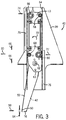
- FIG. 3 is a cutaway side view of an embodiment of a soil monitoring system 40 that may be employed within the agricultural implement of FIG. 1 .
- a pressure sensor 50 is coupled to a leading edge 52 of the sensing shank 42.
- the pressure sensor 50 is configured to output signals indicative of a pressure exerted on the sensor by soil as the sensing shank 42 is driven through the soil along the direction of travel 30.
- the pressure sensor 50 may include a piezoelectric sensor, a mechanical deflection sensor, a fiber optic sensor, a microelectromechanical systems (MEMS) sensor, or any other suitable device configured to output signals based on a measured pressure.
- MEMS microelectromechanical systems
- the senor 50 outputs signals indicative of the pressure sufficient to fracture soil incident upon the leading edge 52 of the sensing shank 42 as the sensing shank 42 oscillates through a desired range of penetration depths. While the illustrated sensor 50 is substantially flush with the leading edge 52 of the sensing shank 42, it should be appreciated that alternative embodiments may employ a recessed sensor, or a sensor that protrudes from the leading edge 52 of the sensing shank 42.
- the pressure sensor 50 is positioned a distance 54 above the bottom edge 56 of the sensing shank 42.
- the distance 54 may be about 1.27 to about 3.8 centimeters, about 1.27 to about 2.5 centimeters, or about 1.9 centimeters.
- the sensor 50 may be located above unstable soil flow patterns associated with interaction between the bottom edge 56 of the sensing shank 42 and the surrounding soil. As a result, the accuracy of the soil fracture pressure measurement may be enhanced.
- the senor 50 contacts substantially undisturbed soil (i.e., soil that has not been fractured by the upper portion of the sensing shank), thereby further increasing the accuracy of the soil fracture pressure measurement. Consequently, the sensor 50 is particularly positioned to facilitate accurate pressure measurements of a contact force 58 between the sensing shank 42 and the soil.
- the sensing shank 42 is coupled to a carrier 60 by a pivot bolt 62 and a shear pin 63.
- the shear pin 63 may break, thereby enabling the sensing shank 42 to rotate about the pivot bolt 62. Because the sensing shank 42 retracts upon contact with an obstruction, the possibility of excessive wear on the shank 42 and/or the sensor 50 may be substantially reduced or eliminated. After the obstruction is cleared, an operator may replace the shear bolt 63, and continue operation of the soil monitoring system 40.
- the carrier 60 is configured to direct movement of the sensing shank 42 in the upward direction 46 and the downward direction 44, and to resist the force 58 applied to the sensing shank 42 by the soil.
- the carrier 60 is disposed within a channel 64 of the frame 20.
- the channel 64 is configured to limit movement of the carrier 60 to the vertical directions 44 and 46 (e.g., the channel 64 is configured to block lateral and longitudinal movement of the carrier 60).
- the carrier 60 includes a first set of roller bearings 66 and a second set of roller bearings 68.
- the roller bearings 66 and 68 are coupled to the carrier 60, and configured to engage an inner surface of the channel 64, thereby facilitating movement of the carrier 60 in the upward direction 46 and the downward direction 44 as the sensing shank 42 is driven to oscillate.
- each roller bearing 66 of the first set is configured to rotate about an axis substantially perpendicular to the direction of travel 30.
- a diameter of each roller bearing 66 of the first set is larger than a diameter of each roller bearing 68 of the second set.
- the roller bearings 66 of the first set are configured to resist the forces and moments associated with contact between the sensing shank 42 and the soil. For example, the contact force 58 between the sensing shank 42 and the soil induces the carrier 60 to rotate in the direction 70. However, the rotation is blocked by contact between the roller bearings 66 and the inner surfaces of the channel 64.
- the roller bearings 66 resist a contact force in the direction 72 between the lower roller bearing 66 and the inner surface of the channel 64, and a contact force 74 between the upper roller bearing 66 and the inner surface of the channel 64.
- the frame 20 includes supports 76 positioned outside of the channel 64 along the path of the roller bearings 66 to provide the frame 20 with additional support against the forces 72 and 74. In this configuration, the roller bearings 66 and 68, and the frame supports 76 enable the sensing shank 42 to move smoothly in the vertical directions 44 and 46, thereby facilitating measurement of soil fracture pressure at a variety of penetration depths.
- FIG. 4 is a cutaway perspective view of the soil monitoring system 40, as shown in FIG. 3 , in which the sensing shank 42 is in a retracted position.
- the soil monitoring system 40 includes a position sensor 78 coupled to the channel 64, and configured to output signals indicative of a position of the sensing shank 42 relative to the frame 20.
- a controller receives the signals from the position sensor 78 and the soil pressure sensor 50, and determines the depth of the compaction layer, and/or generates a map of soil fracture pressure as a function of penetration depth, based on the signals.
- the shank position sensor 78 includes an angled guide 80 coupled to the carrier 60, and a pin 82.
- the pin 82 has a first end 84 configured to couple to a potentiometer, and a second end 86 engaged with the angled guide 80. In this configuration, movement of the carrier 60 in the vertical direction drives the pin 82 to rotate the potentiometer, which in turn, outputs signals indicative of the sensing shank position.
- the second end 86 of the pin 82 is disposed within a groove of the angled guide 80 such that movement of the carrier 60 drives the pin 82 to rotate.
- FIG. 5 is a cutaway perspective view of the soil monitoring system, as shown in FIG. 3 , in which the sensing shank 42 is in an extended position. As illustrated, the pin 82 is rotated from the position shown in FIG. 4 . Accordingly, the potentiometer coupled to the pin 82 outputs signals indicative of the extended position of the sensing shank 42.
- an actuating cylinder 88 extending between the frame 20 and the carrier 60 is configured to linearly drive the carrier 60 in a reciprocating motion to vary the penetration depth of the sensing shank 42 within the soil. As discussed in detail below, the actuating cylinder 88 may be driven by a pressurized fluid (e.g., a pneumatic system, or a hydraulic system).
- the actuating cylinder 88 is configured to drive the sensing shank 42 from a position above the soil surface to a penetration depth of about 40.6 centimeters, about 45.7 centimeters, about 50.8 centimeters, about 55.9 centimeters, or more, thereby enabling the pressure sensor to measure soil fracture pressure throughout a desired range of soil depths.
- a first bar may extend between the frame and a top portion of the carrier, and a second bar may extend between the frame and a bottom portion of the carrier.
- the bars may limit movement of the carrier 60 to the upward and downward directions.
- the bars may also resist the force applied to the sensing shank via contact with the soil, thereby supporting the sensing shank during operation of the soil monitoring system.
- an actuator e.g., mounted to the frame
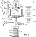
- FIG. 6 is a schematic diagram of an embodiment of the soil monitoring system 40.
- the soil monitoring system 40 includes the actuating cylinder 88, which extends between the frame and the carrier.
- the actuating cylinder includes a cap side 90 and a rod side 92.
- a first fluid conduit 94 is coupled to the cap side 90, and a second fluid conduit 96 is coupled to the rod side 92. Consequently, applying fluid pressure to the first conduit 94 induces the actuating cylinder 88 to extend in the direction 44. Similarly, applying fluid pressure to the second conduit 94 induces the actuating cylinder 88 to retract in the direction 46.
- the actuating cylinder 88 may be reversed such that the first fluid conduit 94 is coupled to the rod side 92, and the second fluid conduit 96 is coupled to the cap side 90.
- applying fluid pressure to the first fluid conduit 94 induces the actuating cylinder 88 to retract in the direction 46
- applying fluid pressure to the second conduit 96 induces the actuating cylinder 88 to extend in the direction 44.
- the actuating cylinder 88 includes a barrel 98 having an end cap 100, a gland 102, and a piston 104.
- the cap side 90 is defined by a volume formed from the piston 104, barrel 98 and end cap 100
- the rod side 92 is defined by a volume formed from the piston 104, barrel 98 and gland 102.
- a rod 106 is coupled to the piston 104 such that movement of the piston 104 drives the rod 106 to translate in the direction 44 and/or 46.
- various seals may be employed between the rod 106 and the gland 102 to block a flow of fluid from exiting the cylinder 88.
- the piston 104 includes additional seals to block a flow of fluid between the cap side 90 and the rod side 92 of the cylinder 88.
- applying fluid pressure to the first conduit 94 increases pressure to the cap side 90 of the actuating cylinder 88, thereby driving the piston 104 and the rod 106 in the direction 44.
- applying fluid pressure to the second conduit 96 increases pressure to the rod side 92 of the actuating cylinder 88, thereby driving the piston 104 and the rod 106 in the direction 46.
- increasing pressure to one conduit may be accompanied by a decrease in pressure to the other conduit to facilitate movement of the piston 104 within the barrel 98.
- the actuating cylinder 88 may be particularly configured to operate based on pneumatic or hydraulic fluid pressure.
- the first conduit 94 and the second conduit 96 are coupled to a depth control valve 108 (e.g., directional control valve).
- the depth control valve 108 is configured to control fluid flow from a fluid power supply to the actuating cylinder 88.
- the directional control valve 108 is a three-position/four-way hydraulic valve configured to control a flow of hydraulic fluid to the cylinder 88.
- a pneumatic directional control valve may be employed in embodiments utilizing a pneumatic cylinder.
- a supply conduit 110 and a return conduit 112 are coupled to the depth control valve 108.
- the supply conduit 110 is configured to provide fluid to the cylinder 88, while the return conduit 112 enables fluid to return to the fluid power supply.
- the fluid power supply may be coupled to the tow vehicle 12.
- the depth control valve 108 includes a first position 114 configured to block fluid flow from the supply and return conduits 110 and 112 to the first and second conduits 94 and 96. While the depth control valve 108 is in the first position 114, fluid pressure within the cap side 90 and the rod side 92 of the cylinder 88 is maintained, thereby holding the sensing shank in a desired position.
- the depth control valve 108 also includes a second position 116 that establishes a fluid connection between the supply conduit 110 and the first conduit 94, and between the return conduit 112 and the second conduit 96.
- the depth control valve 108 While the depth control valve 108 is in the second position 116, fluid flows from the supply conduit 110 to the cap side 90 of the actuating cylinder 88, and from the rod side 92 of the actuating cylinder 88 to the return conduit 112, thereby inducing the piston rod 106 to extend in the direction 44. Consequently, transitioning the depth control valve 108 to the second position 116 drives the sensing shank downwardly, thereby increasing the penetration depth of the pressure sensor. Furthermore, the depth control valve 108 includes a third position 118 that establishes a fluid connection between the supply conduit 110 and the second conduit 96, and between the return conduit 112 and the first conduit 94.
- the depth control valve 108 includes two actuators 120 and 122 configured to adjust the position of the valve 108.
- the first actuator 120 is a solenoid configured to drive the depth control valve 108 to the second position 116
- the second actuator 122 is a solenoid configured to drive the valve 108 to the third position 118.
- Both the first and second actuators 120 and 122 are communicatively coupled to a controller 124 configured to adjust the position of the depth control valve 108. Consequently, the controller 124 may vary the penetration depth of the sensing shank by adjusting the position of the depth control valve 108. For example, the controller 124 may increase the penetration depth of the sensing shank by driving the depth control valve 108 to the second position 116 via the first actuator 120.
- the controller 124 may also decrease the penetration depth of the sensing shank by driving the depth control valve 108 to the third position 118 via the second actuator 122. In this manner, the controller 124 may drive the sensing shank to move in a reciprocating motion between the surface of the soil and a maximum penetration depth, thereby enabling the pressure sensor to measure soil fracture pressure throughout a range of depths.
- the controller 124 is also communicatively coupled to the soil pressure sensor 50, and to the shank position sensor 78. Accordingly, the controller 124 is configured to monitor soil fracture pressure as a function of penetration depth as the sensing shank is driven in a reciprocating motion by the actuating cylinder 88. In addition, the controller 124 is communicatively coupled to a spatial locating device 126 (e.g., global positioning system (GPS) receiver) configured to output signals indicative of a latitude and a longitude of the sensing shank 42. In certain embodiments, the controller 124 is configured to establish a map of soil fracture pressure as a function of penetration depth, latitude and longitude.
- GPS global positioning system
- the controller 124 may be configured to determine a depth of a compaction layer based on the measured soil fracture pressure. In such embodiments, the controller 124 may establish a map of compaction layer depth as a function of latitude and longitude.
- the soil fracture pressure map and/or the compaction layer map may be used by farmers to identify regions of the field having undesirable soil compaction, and/or to compare crop yields to corresponding soil fracture pressures.
- a memory 128 is communicatively coupled to the controller 124.
- the memory 128 is configured to store soil fracture pressure data and/or compaction layer data output by the controller 124. Accordingly, the soil fracture pressure data and/or the compaction layer data may be analyzed after the implement 10 has traversed a field, thereby enabling a farmer to determine whether to perform subsequent ripping operations on the field, and/or to determine whether subsequent ripping operations should be performed on a particular area of the field.
- the controller 124 is communicatively coupled to a user interface 130 having a display 132.
- the compaction layer map (e.g., compaction layer depth as a function of latitude and longitude) and/or the soil fracture pressure map (e.g., soil fracture pressure as a function of penetration depth, latitude and longitude) may be presented on the display 132, thereby enabling an operator to view the data as the measurements are recorded.
- an operator may display maps corresponding to previously recorded soil measurements (e.g., maps stored in the memory 128). In this manner, the operator may determine the effectiveness of previous ripping operations, whether ripping operations should be performed on a particular area of the field, and/or the proper penetration depth for the ripper shank.
- the soil monitoring system may also measure the draft force of the implement 10 (e.g., via a load cell positioned between the tractor and the implement).
- the draft force data may be associated with the latitude and longitude, and stored within the memory 128 and/or presented on the display 132.
- the controller 124 is also communicatively coupled to the adjustable hitch assembly 16, and to the gauge wheel actuator 38. Accordingly, the controller 124 may continuously or periodically adjust the position of the frame 20 relative to the soil surface, and/or the position of the gauge wheels 36 relative to the frame 20 to vary the penetration depth of the ripper shanks.
- the controller 124 may automatically adjust the position of the frame 20 and/or the position of the gauge wheels 36 to place the ripper shanks at a desired depth below the compaction layer to properly fracture the soil.
- the draft of the implement may be substantially less than implements having fixed depth ripper shanks (e.g., set to the maximum expected compaction layer depth).
- the tow vehicle may use less fuel to pull the implement through the field, thereby reducing the costs associated with ripping operations.
- the user interface 130 includes an alarm 134 configured to activate if the soil monitoring system is disengaged and the sensing shank is not in a retracted position. If the alarm 134 is activated, the operator may manually retract the sensing shank to reduce wear while the soil monitoring system is not in operation.
- the user interface 130 includes an input device 136 configured to control operation of the soil monitoring system. In certain embodiments, an operator may input a desired offset distance between the compaction layer and a bottom edge of the ripper shank into the input device 136.
- the input device 136 may include a numeric keypad configured to receive an offset distance in centimeters.
- the controller 124 will adjust the penetration depth of the ripper shanks to the appropriate depth.
- the controller 124 will adjust the penetration depth of the ripper shanks to about 27.9 centimeters.
- the offset distance may be particularly selected to accommodate local variations in the depth of the compaction layer, thereby enhancing soil conditions, facilitating improved crop development, and/or improving crop resistance to reduced moisture. While the offset distance may be manually input in the illustrated embodiment, it should be appreciated that in alternative embodiments, the offset distance may be automatically computed based on soil conditions, such as moisture or density.
- the controller 124 is configured to update the position of the soil surface with each oscillation of the sensing shank, thereby facilitating accurate penetration depth measurements. For example, the controller 124 may instruct the depth control valve 108 to lower the sensing shank toward the soil surface. When the soil pressure sensor 50 detects a fracture pressure that exceeds a threshold value, the controller 124 associates the position of the sensing shank with the soil surface. Consequently, further downward movement of the sensing shank is associated with soil penetration. In addition, once the sensing shank has reached a maximum desired penetration depth, the controller 124 instructs the depth control valve 108 to raise the sensing shank upwardly to a desired distance above the soil surface, where the process repeats.
- the soil monitoring system may accurately determine the depth of the compaction layer, and/or establish accurate maps of soil fracture pressure as a function of penetration depth.
- the controller 124 is configured to set the soil fracture pressure measurement to zero (i.e., nullify/zero the sensor 50) while the soil pressure sensor 50 is positioned above the soil surface. In this manner, the controller 124 may compensate for temperature dependent variations in the sensor measurements, thereby enhancing the accuracy of the measured soil fracture pressure.
- FIG. 7 is a flow diagram of an exemplary method 138 of operating the soil monitoring system.
- the operational state of the soil monitoring system is determined. If the soil monitoring system is not activated, the method proceeds to block 142, in which the position of the sensing shank in determined. If the sensing shank is not retracted, an alarm is activated, as represented by block 144.
- the alarm is activated to alert an operator that movement of the implement may cause the sensing shank to unnecessarily engage the soil, thereby increasing wear on the sensing shank.
- the soil monitoring system may include a locking mechanism configured to hold the sensing shank in the retracted position when the monitoring system is deactivated, thereby reducing the load on the actuating cylinder.
- the sensing shank is lowered toward the soil surface while the implement traverses the field, as represented by block 146.
- the position of the sensing shank is stored, as represented by block 150.
- the threshold value is selected to correspond to an expected minimum soil fracture pressure. Accordingly, a measured soil pressure greater than the threshold value is indicative of soil penetration, and the corresponding stored sensing shank position represents the position of the soil surface.
- the sensing shank continues to move in the downward direction until a maximum desired penetration depth is reached. The sensing shank is then raised in an upwardly direction, as represented by block 152.
- This process repeats while the soil monitoring system is activated, thereby enabling the pressure sensor to measure soil fracture pressure throughout a desired range of penetration depths.
- the pressure sensor measures soil fracture pressure throughout the range of penetration depths.
- a compaction layer depth is determined, as represented by block 154.
- the compaction layer may correspond to a local maxima of soil fracture pressure as a function of penetration depth.
- the latitude, longitude, sensing shank penetration depth, soil fracture pressure and/or compaction layer depth is stored and/or mapped, as represented by block 156.
- latitude and longitude data 158 may be received from a spatial locating device, and used to establish a map of compaction layer depth across a field.
- a three-dimensional map may be generated of the soil fracture pressure as a function of penetration depth, latitude and longitude. Such maps may be used to determine whether to perform ripping operations on a field, and/or to select a penetration depth of a fixed depth ripper shank.
- a penetration depth of the ripper shank may be continuously or periodically adjusted based on the depth of the compaction layer.
- the ripper shank may be positioned below the compaction layer by a desired offset to fracture the soil of the compaction layer. Accordingly, if a depth of the ripper shank is not equal to the depth of the compaction layer plus the offset, as represented by block 160, the depth of the ripper shank is adjusted, as represented by block 162. In this manner, the depth of the ripper shank may be maintained at the desired offset below the compaction layer as the implement traverses the field.
- the ripper shank may be adjusted to a depth of about 15.2 centimeters to fracture the soil, thereby substantially reducing or eliminating the compaction layer.
- the ripper shank is adjusted to compensate, thereby reducing soil compaction throughout the field. Because the depth of the ripper shank is continuously or periodically adjusted while the implement is in operation, the draft of the implement may be substantially less than implements having fixed depth ripper shanks (e.g., set to the maximum expected compaction layer depth plus the offset). As a result, the tow vehicle may use less fuel to pull the implement through the field, thereby reducing the costs associated with ripping operations.
Landscapes
- Life Sciences & Earth Sciences (AREA)
- Engineering & Computer Science (AREA)
- Mechanical Engineering (AREA)
- Soil Sciences (AREA)
- Environmental Sciences (AREA)
- Zoology (AREA)
- Investigation Of Foundation Soil And Reinforcement Of Foundation Soil By Compacting Or Drainage (AREA)
- Soil Working Implements (AREA)
Claims (15)
- Ein Bodenüberwachungssystem (40) mit:einem Meßschaft (42);
einem ersten Sensor (50), der mit einer Vorderkante (52) des Meßschaftes (42) gekoppelt ist, wobei der erste Sensor (50) zur Ausgabe erster Signale konfiguriert ist, die einen Druck anzeigen, der von dem Boden auf den ersten Sensor (50) ausgeübt wird, während der Meßschaft (42) durch den Boden (18) hindurch entlang einer Fahrtrichtung (30) angetrieben wird;
einem Rahmen (20), der einen Kanal (64) bildet, der in einer im wesentlichen vertikalen Richtung gegenüber einer Oberfläche des Bodens (18) ausgerichtet ist;
einem Träger (60), der mit dem Meßschaft (42) verbunden und in dem Kanal (64) angeordnet ist;
einer Anzahl von Kugellagern (66), die mit dem Träger (60) verbunden sind und mit einer Innenoberfläche des Kanals (64) in Eingriff stehen; und
einem Stellglied (38), das sich zwischen dem Rahmen (20) und dem Träger (60) erstreckt, wobei das Stellglied (38) so konfiguriert ist, dass es den Träger (60) linear in einer Hin- und Herbewegung antreibt, um die Eindringtiefe des Meßschaftes (42) in dem Boden (18) zu ändern. - Das Bodenüberwachungssystem (40) nach Anspruch 1, das einen zweiten Sensor (78) umfasst, der mit dem Kanal (64) verbunden und so konfiguriert ist, dass er zweite Signale abgibt, die eine Position des Meßschaftes (42) gegenüber dem Rahmen anzeigen.
- Das Bodenüberwachungssystem (40) nach Anspruch 2, das eine Steuereinrichtung umfasst, die in Kommunikationsverbindung mit dem ersten Sensor (50), dem zweiten Sensor (78) und dem Stellglied (38) steht, wobei die Steuereinrichtung so konfiguriert ist, dass sie die Position der Oberfläche des Bodens (18) gegenüber dem Rahmen (20) und die Eindringtiefe des Meßschaftes (42) unter die Oberfläche des Bodens (18) auf der Grundlage der ersten und zweiten Signale bestimmt.
- Das Bodenüberwachungssystem (40) nach Anspruch 3, bei dem die Steuereinrichtung so konfiguriert ist, dass sie Befehle an das Stellglied (38) liefert, um den Meßschaft (42) zyklisch zwischen einer Position oberhalb der Oberfläche des Bodens (18) und einer vom Benutzer auswählbaren maximalen Eindringtiefe anzutreiben.
- Das Bodenüberwachungssystem (40) nach Anspruch 3, das ein räumliches Lokalisierungsgerät umfasst, das in Kommunikationsverbindung mit der Steuereinrichtung steht, wobei das räumliche Lokalisierungsgerät so konfiguriert ist, dass es dritte Signale abgibt, die einen Breitengrad und einen Längengrad des Meßschaftes (42) anzeigen, und dass die Steuereinrichtung so konfiguriert ist, dass sie vierte Signale abgibt, die den Breitengrad, den Längengrad, die Eindringtiefe und den auf den Sensor ausgeübten Druck, oder eine Kombination hiervon, mit einer gewünschten Frequenz anzeigen.
- Das Bodenüberwachungssystem (40) nach Anspruch 1, das einen Aufreißschaft (24) umfasst, der an dem Rahmen (20) befestigt und hinter dem Meßschaft (42) entlang der Fahrtrichtung (30) angeordnet ist, wobei der Aufreißschaft (24) im Wesentlichen mit dem Meßschaft (42) in einer lateralen Richtung unter einem rechten Winkel zur Fahrtrichtung (30) ausgerichtet ist.
- Das Bodenüberwachungssystem (40) nach Anspruch 6, das eine Steuereinrichtung umfasst, die zur Bestimmung einer Tiefe einer Verdichtungsschicht auf der Grundlage der ersten Signale und zur Einstellung der Eindringtiefe des Aufreißschaftes (24) auf der Grundlage der Tiefe der Verdichtungsschicht konfiguriert ist.
- Das Bodenüberwachungssystem (40) nach Anspruch 1, bei dem die Anzahl von Kugellagern (60) einen ersten Satz von Kugellagern (66) mit einem ersten Durchmesser und einen zweiten Satz von Kugellagern (66) mit einem zweiten Durchmesser umfasst, wobei der erste Durchmesser größer als der zweiten Durchmesser ist und eine Drehachse jedes Kugellagers des ersten Satzes im Wesentlichen unter einem rechten Winkel zur Fahrtrichtung (30) steht.
- Das Bodenüberwachungssystem (40) nach Anspruch 1, bei dem das Stellglied (38) einen Hydraulikzylinder umfasst.
- Das Bodenüberwachungssystem (40) nach Anspruch 1, das eine Alarmeinrichtung zum Aktivieren umfasst, wenn sich der Träger (60) nicht in einer zurückgezogenen Position befindet, wenn das Bodenüberwachungssystem (40) nicht in Betrieb ist.
- Das Bodenüberwachungssystem (40) nach Anspruch 7, bei dem die Steuereinrichtung so konfiguriert ist, dass sie die Eindringtiefe des Aufreißschaftes (24) gegenüber der Tiefe der Verdichtungsschicht auf der Grundlage einer vom Benutzer auswählbaren Versetzung einstellt.
- Das Bodenüberwachungssystem (40) nach Anspruch 6, bei dem der Meßschaft (42) und der Aufreißschaft (24) so konfiguriert sind, dass sie mit einem Arbeitsgerät benachbart zu einer Mittellinie verbunden ist, die sich entlang des Arbeitsgerätes in der Fahrtrichtung (30) erstreckt.
- Das Bodenüberwachungssystem (40) nach Anspruch 6, bei dem der Sensor zumindest ungefähr 1,27 Zentimeter vertikal aufwärts von der Unterkante des Meßschaftes (42) angeordnet ist.
- Das Bodenüberwachungssystem (40) nach Anspruch 4, das einen Aufreißschaft (24) umfasst, wobei die Steuereinrichtung so konfiguriert ist, dass sie eine Tiefe einer Verdichtungsschicht auf der Grundlage der Signale bestimmt und die Eindringtiefe des Aufreißschaftes (24) auf der Grundlage der Tiefe der Verdichtungsschicht einstellt.
- Das Bodenüberwachungssystem (40) nach Anspruch 14, bei dem die Steuereinrichtung so konfiguriert ist, dass sie Befehle an eine Anhängerkupplung zur Einstellung der vertikalen Position des Rahmens (20) gegenüber der Oberfläche des Bodens, Befehle an ein Meßrad-Stellglied (38) zur Einstellung der vertikalen Position des Meßrades relativ zum Rahmen, oder eine Kombination hiervon liefert, um die Eindringtiefe des Aufreißschaftes (24) einzustellen.
Applications Claiming Priority (2)
| Application Number | Priority Date | Filing Date | Title |
|---|---|---|---|
| US13/352,001 US8827001B2 (en) | 2012-01-17 | 2012-01-17 | Soil monitoring system |
| PCT/IB2013/050451 WO2013108214A2 (en) | 2012-01-17 | 2013-01-17 | Soil monitoring system |
Publications (2)
| Publication Number | Publication Date |
|---|---|
| EP2804459A2 EP2804459A2 (de) | 2014-11-26 |
| EP2804459B1 true EP2804459B1 (de) | 2016-04-06 |
Family
ID=48050066
Family Applications (1)
| Application Number | Title | Priority Date | Filing Date |
|---|---|---|---|
| EP13714689.0A Active EP2804459B1 (de) | 2012-01-17 | 2013-01-17 | Bodenüberwachungssystem |
Country Status (4)
| Country | Link |
|---|---|
| US (1) | US8827001B2 (de) |
| EP (1) | EP2804459B1 (de) |
| RU (1) | RU2014133563A (de) |
| WO (1) | WO2013108214A2 (de) |
Families Citing this family (77)
| Publication number | Priority date | Publication date | Assignee | Title |
|---|---|---|---|---|
| US9422690B2 (en) * | 2012-11-30 | 2016-08-23 | Michael W. N. Wilson | Method and apparatus for performing burial assessment surveys |
| UA118026C2 (uk) * | 2013-03-14 | 2018-11-12 | Пресіжн Плентінг Елелсі | Система (варіанти), спосіб (варіанти) і пристрій керування глибиною борозни сільськогосподарського знаряддя і контролю ґрунту |
| WO2014162261A1 (en) * | 2013-04-02 | 2014-10-09 | Roger Arnold Stromsoe | A soil compaction system and method |
| US20150020612A1 (en) * | 2013-07-17 | 2015-01-22 | Ag Leader Technology | Method and means to monitor seeder row unit downforce |
| US9405039B2 (en) * | 2014-04-22 | 2016-08-02 | Deere & Company | Ground engaging member accumulation determination |
| US10785905B2 (en) | 2014-05-08 | 2020-09-29 | Precision Planting Llc | Liquid application apparatus comprising a seed firmer |
| US20160029547A1 (en) * | 2014-07-30 | 2016-02-04 | Deere & Company | Sensing the soil profile behind a soil-engaging implement |
| US20160076205A1 (en) * | 2014-09-16 | 2016-03-17 | Caterpillar Paving Products Inc. | Device and Process for Controlling Compaction Based on Previously Mapped Data |
| CN104599474B (zh) * | 2015-02-04 | 2018-06-19 | 青岛农业大学 | 一种振动式深松机作业状态监控系统 |
| AU2016324138C1 (en) * | 2015-09-18 | 2020-11-19 | Precision Planting Llc | Apparatus, system and method for monitoring soil criteria during tillage operations and control of tillage tools |
| CN105300570B (zh) * | 2015-11-20 | 2018-02-27 | 深圳大学 | 零应变土压力传感器 |
| US10440877B2 (en) | 2016-08-18 | 2019-10-15 | Cnh Industrial America Llc | Residue management based on topography by an agricultural tillage implement |
| US10178823B2 (en) * | 2016-12-12 | 2019-01-15 | Cnh Industrial Canada, Ltd. | Agricultural implement with automatic shank depth control |
| US10512212B2 (en) | 2016-12-19 | 2019-12-24 | The Climate Corporation | Systems, methods, and apparatus for soil and seed monitoring |
| US10225983B2 (en) | 2017-03-27 | 2019-03-12 | Cnh Industrial America Llc | Remote hydraulic positioning of an implement stabilizer wheel |
| US10420272B2 (en) | 2017-03-31 | 2019-09-24 | Cnh Industrial America Llc | Seedbed condition monitoring system when performing field operations |
| US10645860B2 (en) | 2017-03-31 | 2020-05-12 | Cnh Industrial America Llc | Seedbed condition monitoring system with a seedbed surface detection assembly |
| US10624253B2 (en) | 2017-03-31 | 2020-04-21 | Cnh Industrial America Llc | Seedbed condition monitoring system with a seedbed floor detection assembly |
| CN107091732B (zh) * | 2017-04-18 | 2023-06-06 | 西华大学 | 往复式可变参数圆盘犁寿命测试系统 |
| US10542656B2 (en) | 2017-04-27 | 2020-01-28 | Cnh Industrial America Llc | Remote electrical positioning of an implement stabilizer wheel |
| US11985913B2 (en) | 2017-04-27 | 2024-05-21 | Cnh Industrial America Llc | Soil monitoring system |
| US11259454B2 (en) | 2017-04-28 | 2022-03-01 | Cnh Industrial America Llc | System and method for detecting ground engaging tool float for an agricultural implement |
| US10561056B2 (en) | 2017-04-28 | 2020-02-18 | Cnh Industrial America Llc | System and method for monitoring soil conditions within a field |
| US10481142B2 (en) * | 2017-05-25 | 2019-11-19 | Deere & Company | Sensor system for determining soil characteristics |
| US11224153B2 (en) | 2017-07-28 | 2022-01-18 | Kinze Manufacturing, Inc. | Agricultural implement and row units including double acting actuator systems, methods, and apparatus |
| BR122020026139B1 (pt) | 2017-10-02 | 2023-11-14 | Precision Planting Llc | Aparelho de solo para firmar uma semente em uma vala |
| NL2020077B1 (nl) * | 2017-12-13 | 2019-06-21 | Lely Patent Nv | Autonoom landbouwvoertuig |
| WO2019118758A1 (en) | 2017-12-15 | 2019-06-20 | Kinze Manufacturing, Inc. | Systems, methods, and apparatus for controlling downforce of an agricultural implement |
| US10838432B2 (en) | 2018-01-26 | 2020-11-17 | Cnh Industrial Canada, Ltd. | System and method for monitoring frame levelness of an agricultural implement |
| US11297757B2 (en) | 2018-02-13 | 2022-04-12 | Cnh Industrial America Llc | System for monitoring the displacement of a ground engaging tool |
| US20190320574A1 (en) * | 2018-04-18 | 2019-10-24 | Cnh Industrial America Llc | System for creating soil compaction maps and associated methods for controlling the operation of a tillage implement |
| US10650538B2 (en) | 2018-06-27 | 2020-05-12 | Cnh Industrial Canada, Ltd. | Detecting and measuring the size of clods and other soil features from imagery |
| US11395452B2 (en) * | 2018-06-29 | 2022-07-26 | Deere & Company | Method of mitigating compaction and a compaction mitigation system |
| US10757854B2 (en) | 2018-08-27 | 2020-09-01 | Cnh Industrial America Llc | Determining forces exerted on rolling agricultural components based on an applied braking force |
| US10820472B2 (en) * | 2018-09-18 | 2020-11-03 | Cnh Industrial America Llc | System and method for determining soil parameters of a field at a selected planting depth during agricultural operations |
| US11041716B2 (en) | 2018-10-16 | 2021-06-22 | Cnh Industrial America Llc | System and method for monitoring operational parameters associated with a tillage implement during the performance of a field operation |
| US10973171B2 (en) * | 2018-10-17 | 2021-04-13 | Cnh Industrial America Llc | System and method for monitoring field profiles based on data from multiple types of sensors |
| US10918008B2 (en) | 2018-11-30 | 2021-02-16 | Cnh Industrial America Llc | System and method for generating a prescription map for an agricultural implement based on soil compaction |
| US11039563B2 (en) | 2019-01-11 | 2021-06-22 | Cnh Industrial America Llc | System for monitoring the condition of a seedbed within a field with a seedbed floor detection assembly |
| US11343956B2 (en) * | 2019-02-18 | 2022-05-31 | Cnh Industrial Canada, Ltd. | System and method for monitoring soil conditions within a field |
| US11711994B2 (en) * | 2019-03-29 | 2023-08-01 | Cnh Industrial Canada, Ltd. | System and method for monitoring the condition of a lateral swath of a seedbed with a seedbed floor detection assembly |
| WO2020208430A1 (en) * | 2019-04-11 | 2020-10-15 | Agco Corporation | Tillage implements and methods of identifying a compaction layer |
| EP3729934A1 (de) | 2019-04-25 | 2020-10-28 | CNH Industrial Sweden AB | Pflug |
| US11707010B2 (en) * | 2019-06-14 | 2023-07-25 | Cnh Industrial America Llc | System and method for monitoring the operational status of tools of an agricultural implement |
| US11206753B2 (en) | 2019-06-14 | 2021-12-28 | Cnh Industrial America Llc | System and method for controlling an agricultural implement during the performance of a tillage operation |
| US10959362B2 (en) | 2019-06-21 | 2021-03-30 | SmarTerra, LLC | Turf maintenance system |
| US11622496B2 (en) | 2019-06-24 | 2023-04-11 | Cnh Industrial Canada, Ltd. | Smart sensor system for agricultural implements |
| US20210045279A1 (en) * | 2019-08-15 | 2021-02-18 | Cnh Industrial America Llc | Tillage system with variable fertilizer application and tool depth adjustment |
| US11793098B2 (en) | 2019-08-27 | 2023-10-24 | Cnh Industrial America Llc | System and method for detecting levelness of tools of a tillage implement based on material flow |
| US11219153B2 (en) * | 2019-08-29 | 2022-01-11 | Cnh Industrial America Llc | System and method for monitoring shank float |
| US11895941B2 (en) | 2019-09-23 | 2024-02-13 | Cnh Industrial America Llc | Tillage system with variable fertilizer application |
| US11419254B2 (en) | 2019-10-28 | 2022-08-23 | Cnh Industrial Canada, Ltd. | System and method for detecting levelness of tools of a tillage implement based on tool loading |
| US11330754B2 (en) | 2019-10-30 | 2022-05-17 | Cnh Industrial America Llc | Systems and methods for assessing the performance of an agricultural implement |
| US11805721B2 (en) | 2019-10-31 | 2023-11-07 | Deere & Company | Work machine control systems to monitor ground engagement tools and map obstacles |
| US11483960B2 (en) * | 2019-11-19 | 2022-11-01 | Cnh Industrial Canada, Ltd. | System and method for monitoring seedbed conditions using a seedbed sensing assembly supported on a UAV |
| US11528836B2 (en) | 2019-11-22 | 2022-12-20 | Cnh Industrial America Llc | System and method for sequentially controlling agricultural implement ground-engaging tools |
| US11832545B2 (en) | 2019-12-31 | 2023-12-05 | Cnh Industrial America Llc | System and method for operating ground engaging tools based on measured soil moisture |
| US12016257B2 (en) | 2020-02-19 | 2024-06-25 | Sabanto, Inc. | Methods for detecting and clearing debris from planter gauge wheels, closing wheels and seed tubes |
| US11602092B2 (en) | 2020-03-26 | 2023-03-14 | Cnh Industrial America Llc | Frame control system for an agricultural implement |
| US12022756B2 (en) | 2020-03-26 | 2024-07-02 | Cnh Industrial America Llc | Orientation control system for an agricultural implement |
| US11558993B2 (en) | 2020-03-26 | 2023-01-24 | Cnh Industrial America Llc | Soil monitoring system for an agricultural tillage implement |
| US11730076B2 (en) | 2020-03-26 | 2023-08-22 | Cnh Industrial America Llc | Control system for an agricultural implement |
| US11638393B2 (en) | 2020-03-26 | 2023-05-02 | Cnh Industrial America Llc | Ground engaging tool monitoring system |
| US11617294B2 (en) | 2020-03-26 | 2023-04-04 | Cnh Industrial America Llc | Orientation control system for an agricultural implement |
| EP4175451B1 (de) | 2020-07-02 | 2024-10-23 | Precision Planting LLC | Geräte und methoden zur messung der bodenbeschaffenheit |
| US12461083B2 (en) | 2020-08-03 | 2025-11-04 | Sabanto, Inc. | Methods for improved agricultural procedures |
| US12185650B2 (en) | 2021-01-29 | 2025-01-07 | Cnh Industrial Canada, Ltd. | System and method for controlling the operation of an agricultural implement based on compaction layer position |
| US12150397B2 (en) | 2021-03-19 | 2024-11-26 | Cnh Industrial America Llc | System and method for monitoring an operational status of a shear pin for a ground-engaging assembly of an agricultural implement |
| US11980113B2 (en) * | 2021-05-17 | 2024-05-14 | Cnh Industrial America Llc | System and method for adjusting actuator pressure on an agricultural implement using a valve |
| US12340637B2 (en) | 2021-06-16 | 2025-06-24 | Deere & Company | Implement management system for implement wear detection and estimation |
| US12610877B2 (en) | 2021-11-23 | 2026-04-28 | Cnh Industrial America Llc | Agricultural system and method for determining a trip magnitude of a ground engaging tool of an agricultural implement |
| CN114487012B (zh) * | 2021-12-29 | 2023-11-03 | 南京大学 | 一种土体表面裂隙发育预判方法 |
| CN115031711B (zh) * | 2022-07-13 | 2023-10-31 | 山东省煤田地质局物探测量队 | 一种国土空间测绘用地理信息采集装置 |
| US12324367B2 (en) * | 2022-12-09 | 2025-06-10 | Cnh Industrial America Llc | System and method for selectively activating soil sensors of an agricultural implement |
| US12276088B2 (en) | 2023-03-09 | 2025-04-15 | Cnh Industrial Canada, Ltd. | Agricultural system and method for detecting failure of a ground-engaging tool of an agricultural implement |
| AR133777A1 (es) * | 2024-09-11 | 2025-10-29 | Earthworms S A S | Conjunto regulador de maquinaria agrícola para procesos de acondicionamiento de suelo en profundidad o descompactación a tasa variable y método para su utilización |
| CN119111306B (zh) * | 2024-11-11 | 2025-01-28 | 四川省农业科学院植物保护研究所 | 一种甘薯种植铺膜机 |
Family Cites Families (28)
| Publication number | Priority date | Publication date | Assignee | Title |
|---|---|---|---|---|
| US1911349A (en) * | 1932-06-20 | 1933-05-30 | Raleigh A Byrd | Cultivator attachment |
| US3136371A (en) * | 1959-09-05 | 1964-06-09 | Porsche Diesel Motorenbau G M | Tractor arrangement |
| US3058243A (en) | 1961-12-14 | 1962-10-16 | Loland T Mcgee | Earth working implement |
| US4044838A (en) * | 1975-04-21 | 1977-08-30 | American Tractor Equipment Corporation | Automatic control for ripper tool |
| GB1580643A (en) * | 1976-10-15 | 1980-12-03 | Texas Industries Inc | Soil cultivating implements |
| US4248310A (en) | 1979-06-28 | 1981-02-03 | Mcwilliams William R | Skip row cultivators |
| US4444271A (en) * | 1980-12-29 | 1984-04-24 | Dmi, Inc. | Tillage apparatus with independent depth adjustment |
| US4600060A (en) * | 1983-10-28 | 1986-07-15 | Deere & Company | Depth sensing structure for an agricultural implement |
| US5033031A (en) * | 1990-01-09 | 1991-07-16 | Ford New Holland | Underground ultrasonic tillage depth sensor |
| US5524560A (en) * | 1994-12-09 | 1996-06-11 | The United States Of America As Represented By The Department Of Agriculture | System for controlling vertical displacement of agricultural implements into the soil |
| US6062090A (en) | 1996-07-31 | 2000-05-16 | Transportation Technology Center, Inc. | Apparatus and method for determining the strength and type of soil |
| US5938709A (en) | 1996-11-22 | 1999-08-17 | Case Corporation | Panning display of GPS field maps |
| US6041582A (en) | 1998-02-20 | 2000-03-28 | Case Corporation | System for recording soil conditions |
| US6119069A (en) | 1999-03-01 | 2000-09-12 | Case Corporation | System and method for deriving field boundaries using alpha shapes |
| US6497153B1 (en) | 2000-09-28 | 2002-12-24 | Bechtel Bwxt Idaho, Llc | Measuring spatial variability in soil characteristics |
| US6853937B2 (en) | 2001-07-06 | 2005-02-08 | Tokyo University Of Agriculture And Technology Tlo Co., Ltd. | Soil characteristics survey device and soil characteristics survey method |
| US6834550B2 (en) | 2001-09-10 | 2004-12-28 | The Regents Of The University Of California | Soil profile force measurement using an instrumented tine |
| US6597992B2 (en) | 2001-11-01 | 2003-07-22 | Soil And Topography Information, Llc | Soil and topography surveying |
| US6389999B1 (en) | 2001-11-02 | 2002-05-21 | Dennis Duello | Dynamic controller of excess downpressure for surface engaging implement |
| US6647799B1 (en) | 2002-01-16 | 2003-11-18 | The United States Of America As Represented By The Secretary Of Agriculture | Soil strength measurement for site-specific agriculture |
| US6701857B1 (en) | 2003-01-16 | 2004-03-09 | Lynn David Jensen | Depth control device for planting implement |
| US7028554B2 (en) | 2003-07-11 | 2006-04-18 | Deere & Company | Instrumented deep tillage implement |
| US7428455B2 (en) | 2004-10-12 | 2008-09-23 | Caterpillar Inc. | Compaction indication by effective rolling radius |
| US7104340B1 (en) | 2005-03-22 | 2006-09-12 | Deere & Company | Towed implement draft force sensor |
| US7317988B2 (en) | 2005-08-17 | 2008-01-08 | Ag Leader Technology, Inc. | Method for automatically optimizing the legend for real-time mapping |
| GB0601634D0 (en) | 2006-01-26 | 2006-03-08 | Scandinavian Highlands As | Sub-surface analysis of particulate substrates |
| US20070239338A1 (en) | 2006-04-06 | 2007-10-11 | Dean Potts | Worksite preparation method using compaction response and mapping information |
| DE102010000218A1 (de) | 2010-01-27 | 2011-07-28 | Amazonen-Werke H. Dreyer GmbH & Co. KG, 49205 | Halterungsanordnung |
-
2012
- 2012-01-17 US US13/352,001 patent/US8827001B2/en active Active
-
2013
- 2013-01-17 EP EP13714689.0A patent/EP2804459B1/de active Active
- 2013-01-17 WO PCT/IB2013/050451 patent/WO2013108214A2/en not_active Ceased
- 2013-01-17 RU RU2014133563A patent/RU2014133563A/ru not_active Application Discontinuation
Also Published As
| Publication number | Publication date |
|---|---|
| US20130180742A1 (en) | 2013-07-18 |
| WO2013108214A3 (en) | 2014-01-23 |
| RU2014133563A (ru) | 2016-03-10 |
| EP2804459A2 (de) | 2014-11-26 |
| WO2013108214A2 (en) | 2013-07-25 |
| US8827001B2 (en) | 2014-09-09 |
Similar Documents
| Publication | Publication Date | Title |
|---|---|---|
| EP2804459B1 (de) | Bodenüberwachungssystem | |
| RU2720278C2 (ru) | Устройство, система и способ мониторинга критериев почвы во время операций обработки почвы и управление почвообрабатывающими рабочими органами | |
| RU2580449C2 (ru) | Система и способ управления обработкой почвы сельскохозяйственным орудием (варианты) | |
| EP3400764B1 (de) | System und verfahren zur erkennung des aufschwimmens eines bodeneingriffswerkzeugs für ein landwirtschaftliches arbeitsgerät | |
| CN101946576B (zh) | 一种圆盘式开沟器开沟深度自动控制系统 | |
| RU2655204C2 (ru) | Устройства, способы и системы для обеспечения прижимного усилия для сельскохозяйственного орудия | |
| US6389999B1 (en) | Dynamic controller of excess downpressure for surface engaging implement | |
| US9433142B2 (en) | Tool control system for agricultural seeders | |
| US10334771B2 (en) | Wheel position control system for an agricultural implement | |
| US20120125244A1 (en) | Mapping soil hardness | |
| EP4021159B1 (de) | System und verfahren zur überwachung eines schaftschwimmers | |
| EP4233504B1 (de) | Kombination eines bodendichteerkennungssystems und landwirtschaftliches arbeitsgerät | |
| CN110692299B (zh) | 对行探测装置、中耕装置、中耕追肥机及其控制方法 | |
| Novák et al. | Measurement of stubble cultivator draught force under different soil conditions. | |
| CN210868649U (zh) | 对行探测装置、中耕装置及中耕追肥机 | |
| Godwin et al. | Choosing and evaluating soil improvements by subsoiling and compaction control. | |
| CA2784210C (en) | Tool control system for agricultural seeders | |
| US11711994B2 (en) | System and method for monitoring the condition of a lateral swath of a seedbed with a seedbed floor detection assembly | |
| Atajanov et al. | Requirements for the machine providing the formation of irrigation foundations | |
| US20250275496A1 (en) | Independent wing position control for an agricultural implement |
Legal Events
| Date | Code | Title | Description |
|---|---|---|---|
| PUAI | Public reference made under article 153(3) epc to a published international application that has entered the european phase |
Free format text: ORIGINAL CODE: 0009012 |
|
| 17P | Request for examination filed |
Effective date: 20140818 |
|
| AK | Designated contracting states |
Kind code of ref document: A2 Designated state(s): AL AT BE BG CH CY CZ DE DK EE ES FI FR GB GR HR HU IE IS IT LI LT LU LV MC MK MT NL NO PL PT RO RS SE SI SK SM TR |
|
| DAX | Request for extension of the european patent (deleted) | ||
| GRAP | Despatch of communication of intention to grant a patent |
Free format text: ORIGINAL CODE: EPIDOSNIGR1 |
|
| INTG | Intention to grant announced |
Effective date: 20151001 |
|
| GRAS | Grant fee paid |
Free format text: ORIGINAL CODE: EPIDOSNIGR3 |
|
| GRAA | (expected) grant |
Free format text: ORIGINAL CODE: 0009210 |
|
| AK | Designated contracting states |
Kind code of ref document: B1 Designated state(s): AL AT BE BG CH CY CZ DE DK EE ES FI FR GB GR HR HU IE IS IT LI LT LU LV MC MK MT NL NO PL PT RO RS SE SI SK SM TR |
|
| REG | Reference to a national code |
Ref country code: GB Ref legal event code: FG4D |
|
| REG | Reference to a national code |
Ref country code: AT Ref legal event code: REF Ref document number: 786642 Country of ref document: AT Kind code of ref document: T Effective date: 20160415 Ref country code: CH Ref legal event code: EP |
|
| REG | Reference to a national code |
Ref country code: IE Ref legal event code: FG4D |
|
| REG | Reference to a national code |
Ref country code: DE Ref legal event code: R096 Ref document number: 602013006275 Country of ref document: DE |
|
| REG | Reference to a national code |
Ref country code: LT Ref legal event code: MG4D Ref country code: NL Ref legal event code: MP Effective date: 20160406 |
|
| REG | Reference to a national code |
Ref country code: AT Ref legal event code: MK05 Ref document number: 786642 Country of ref document: AT Kind code of ref document: T Effective date: 20160406 |
|
| PG25 | Lapsed in a contracting state [announced via postgrant information from national office to epo] |
Ref country code: NL Free format text: LAPSE BECAUSE OF FAILURE TO SUBMIT A TRANSLATION OF THE DESCRIPTION OR TO PAY THE FEE WITHIN THE PRESCRIBED TIME-LIMIT Effective date: 20160406 |
|
| PG25 | Lapsed in a contracting state [announced via postgrant information from national office to epo] |
Ref country code: IS Free format text: LAPSE BECAUSE OF FAILURE TO SUBMIT A TRANSLATION OF THE DESCRIPTION OR TO PAY THE FEE WITHIN THE PRESCRIBED TIME-LIMIT Effective date: 20160806 Ref country code: LT Free format text: LAPSE BECAUSE OF FAILURE TO SUBMIT A TRANSLATION OF THE DESCRIPTION OR TO PAY THE FEE WITHIN THE PRESCRIBED TIME-LIMIT Effective date: 20160406 Ref country code: NO Free format text: LAPSE BECAUSE OF FAILURE TO SUBMIT A TRANSLATION OF THE DESCRIPTION OR TO PAY THE FEE WITHIN THE PRESCRIBED TIME-LIMIT Effective date: 20160706 Ref country code: FI Free format text: LAPSE BECAUSE OF FAILURE TO SUBMIT A TRANSLATION OF THE DESCRIPTION OR TO PAY THE FEE WITHIN THE PRESCRIBED TIME-LIMIT Effective date: 20160406 Ref country code: PL Free format text: LAPSE BECAUSE OF FAILURE TO SUBMIT A TRANSLATION OF THE DESCRIPTION OR TO PAY THE FEE WITHIN THE PRESCRIBED TIME-LIMIT Effective date: 20160406 |
|
| PG25 | Lapsed in a contracting state [announced via postgrant information from national office to epo] |
Ref country code: LV Free format text: LAPSE BECAUSE OF FAILURE TO SUBMIT A TRANSLATION OF THE DESCRIPTION OR TO PAY THE FEE WITHIN THE PRESCRIBED TIME-LIMIT Effective date: 20160406 Ref country code: RS Free format text: LAPSE BECAUSE OF FAILURE TO SUBMIT A TRANSLATION OF THE DESCRIPTION OR TO PAY THE FEE WITHIN THE PRESCRIBED TIME-LIMIT Effective date: 20160406 Ref country code: GR Free format text: LAPSE BECAUSE OF FAILURE TO SUBMIT A TRANSLATION OF THE DESCRIPTION OR TO PAY THE FEE WITHIN THE PRESCRIBED TIME-LIMIT Effective date: 20160707 Ref country code: HR Free format text: LAPSE BECAUSE OF FAILURE TO SUBMIT A TRANSLATION OF THE DESCRIPTION OR TO PAY THE FEE WITHIN THE PRESCRIBED TIME-LIMIT Effective date: 20160406 Ref country code: AT Free format text: LAPSE BECAUSE OF FAILURE TO SUBMIT A TRANSLATION OF THE DESCRIPTION OR TO PAY THE FEE WITHIN THE PRESCRIBED TIME-LIMIT Effective date: 20160406 Ref country code: ES Free format text: LAPSE BECAUSE OF FAILURE TO SUBMIT A TRANSLATION OF THE DESCRIPTION OR TO PAY THE FEE WITHIN THE PRESCRIBED TIME-LIMIT Effective date: 20160406 Ref country code: PT Free format text: LAPSE BECAUSE OF FAILURE TO SUBMIT A TRANSLATION OF THE DESCRIPTION OR TO PAY THE FEE WITHIN THE PRESCRIBED TIME-LIMIT Effective date: 20160808 Ref country code: SE Free format text: LAPSE BECAUSE OF FAILURE TO SUBMIT A TRANSLATION OF THE DESCRIPTION OR TO PAY THE FEE WITHIN THE PRESCRIBED TIME-LIMIT Effective date: 20160406 |
|
| PG25 | Lapsed in a contracting state [announced via postgrant information from national office to epo] |
Ref country code: BE Free format text: LAPSE BECAUSE OF FAILURE TO SUBMIT A TRANSLATION OF THE DESCRIPTION OR TO PAY THE FEE WITHIN THE PRESCRIBED TIME-LIMIT Effective date: 20160406 |
|
| REG | Reference to a national code |
Ref country code: DE Ref legal event code: R097 Ref document number: 602013006275 Country of ref document: DE |
|
| REG | Reference to a national code |
Ref country code: FR Ref legal event code: PLFP Year of fee payment: 5 |
|
| PG25 | Lapsed in a contracting state [announced via postgrant information from national office to epo] |
Ref country code: RO Free format text: LAPSE BECAUSE OF FAILURE TO SUBMIT A TRANSLATION OF THE DESCRIPTION OR TO PAY THE FEE WITHIN THE PRESCRIBED TIME-LIMIT Effective date: 20160406 Ref country code: SK Free format text: LAPSE BECAUSE OF FAILURE TO SUBMIT A TRANSLATION OF THE DESCRIPTION OR TO PAY THE FEE WITHIN THE PRESCRIBED TIME-LIMIT Effective date: 20160406 Ref country code: DK Free format text: LAPSE BECAUSE OF FAILURE TO SUBMIT A TRANSLATION OF THE DESCRIPTION OR TO PAY THE FEE WITHIN THE PRESCRIBED TIME-LIMIT Effective date: 20160406 Ref country code: CZ Free format text: LAPSE BECAUSE OF FAILURE TO SUBMIT A TRANSLATION OF THE DESCRIPTION OR TO PAY THE FEE WITHIN THE PRESCRIBED TIME-LIMIT Effective date: 20160406 Ref country code: EE Free format text: LAPSE BECAUSE OF FAILURE TO SUBMIT A TRANSLATION OF THE DESCRIPTION OR TO PAY THE FEE WITHIN THE PRESCRIBED TIME-LIMIT Effective date: 20160406 |
|
| PLBE | No opposition filed within time limit |
Free format text: ORIGINAL CODE: 0009261 |
|
| STAA | Information on the status of an ep patent application or granted ep patent |
Free format text: STATUS: NO OPPOSITION FILED WITHIN TIME LIMIT |
|
| PG25 | Lapsed in a contracting state [announced via postgrant information from national office to epo] |
Ref country code: SM Free format text: LAPSE BECAUSE OF FAILURE TO SUBMIT A TRANSLATION OF THE DESCRIPTION OR TO PAY THE FEE WITHIN THE PRESCRIBED TIME-LIMIT Effective date: 20160406 |
|
| 26N | No opposition filed |
Effective date: 20170110 |
|
| PG25 | Lapsed in a contracting state [announced via postgrant information from national office to epo] |
Ref country code: SI Free format text: LAPSE BECAUSE OF FAILURE TO SUBMIT A TRANSLATION OF THE DESCRIPTION OR TO PAY THE FEE WITHIN THE PRESCRIBED TIME-LIMIT Effective date: 20160406 |
|
| REG | Reference to a national code |
Ref country code: CH Ref legal event code: PL |
|
| PG25 | Lapsed in a contracting state [announced via postgrant information from national office to epo] |
Ref country code: MC Free format text: LAPSE BECAUSE OF FAILURE TO SUBMIT A TRANSLATION OF THE DESCRIPTION OR TO PAY THE FEE WITHIN THE PRESCRIBED TIME-LIMIT Effective date: 20160406 |
|
| PG25 | Lapsed in a contracting state [announced via postgrant information from national office to epo] |
Ref country code: LI Free format text: LAPSE BECAUSE OF NON-PAYMENT OF DUE FEES Effective date: 20170131 Ref country code: CH Free format text: LAPSE BECAUSE OF NON-PAYMENT OF DUE FEES Effective date: 20170131 |
|
| REG | Reference to a national code |
Ref country code: IE Ref legal event code: MM4A |
|
| PG25 | Lapsed in a contracting state [announced via postgrant information from national office to epo] |
Ref country code: LU Free format text: LAPSE BECAUSE OF NON-PAYMENT OF DUE FEES Effective date: 20170117 |
|
| REG | Reference to a national code |
Ref country code: FR Ref legal event code: PLFP Year of fee payment: 6 |
|
| PG25 | Lapsed in a contracting state [announced via postgrant information from national office to epo] |
Ref country code: IE Free format text: LAPSE BECAUSE OF NON-PAYMENT OF DUE FEES Effective date: 20170117 Ref country code: IT Free format text: LAPSE BECAUSE OF NON-PAYMENT OF DUE FEES Effective date: 20170117 |
|
| PG25 | Lapsed in a contracting state [announced via postgrant information from national office to epo] |
Ref country code: MT Free format text: LAPSE BECAUSE OF NON-PAYMENT OF DUE FEES Effective date: 20170117 |
|
| PG25 | Lapsed in a contracting state [announced via postgrant information from national office to epo] |
Ref country code: AL Free format text: LAPSE BECAUSE OF FAILURE TO SUBMIT A TRANSLATION OF THE DESCRIPTION OR TO PAY THE FEE WITHIN THE PRESCRIBED TIME-LIMIT Effective date: 20160406 |
|
| PG25 | Lapsed in a contracting state [announced via postgrant information from national office to epo] |
Ref country code: HU Free format text: LAPSE BECAUSE OF FAILURE TO SUBMIT A TRANSLATION OF THE DESCRIPTION OR TO PAY THE FEE WITHIN THE PRESCRIBED TIME-LIMIT; INVALID AB INITIO Effective date: 20130117 |
|
| PG25 | Lapsed in a contracting state [announced via postgrant information from national office to epo] |
Ref country code: BG Free format text: LAPSE BECAUSE OF FAILURE TO SUBMIT A TRANSLATION OF THE DESCRIPTION OR TO PAY THE FEE WITHIN THE PRESCRIBED TIME-LIMIT Effective date: 20160406 |
|
| PG25 | Lapsed in a contracting state [announced via postgrant information from national office to epo] |
Ref country code: CY Free format text: LAPSE BECAUSE OF FAILURE TO SUBMIT A TRANSLATION OF THE DESCRIPTION OR TO PAY THE FEE WITHIN THE PRESCRIBED TIME-LIMIT Effective date: 20160406 |
|
| PG25 | Lapsed in a contracting state [announced via postgrant information from national office to epo] |
Ref country code: MK Free format text: LAPSE BECAUSE OF FAILURE TO SUBMIT A TRANSLATION OF THE DESCRIPTION OR TO PAY THE FEE WITHIN THE PRESCRIBED TIME-LIMIT Effective date: 20160406 |
|
| PG25 | Lapsed in a contracting state [announced via postgrant information from national office to epo] |
Ref country code: TR Free format text: LAPSE BECAUSE OF FAILURE TO SUBMIT A TRANSLATION OF THE DESCRIPTION OR TO PAY THE FEE WITHIN THE PRESCRIBED TIME-LIMIT Effective date: 20160406 |
|
| PGFP | Annual fee paid to national office [announced via postgrant information from national office to epo] |
Ref country code: GB Payment date: 20260126 Year of fee payment: 14 |
|
| PGFP | Annual fee paid to national office [announced via postgrant information from national office to epo] |
Ref country code: DE Payment date: 20260127 Year of fee payment: 14 |
|
| PGFP | Annual fee paid to national office [announced via postgrant information from national office to epo] |
Ref country code: FR Payment date: 20260126 Year of fee payment: 14 |