US11224153B2 - Agricultural implement and row units including double acting actuator systems, methods, and apparatus - Google Patents
Agricultural implement and row units including double acting actuator systems, methods, and apparatus Download PDFInfo
- Publication number
- US11224153B2 US11224153B2 US16/047,236 US201816047236A US11224153B2 US 11224153 B2 US11224153 B2 US 11224153B2 US 201816047236 A US201816047236 A US 201816047236A US 11224153 B2 US11224153 B2 US 11224153B2
- Authority
- US
- United States
- Prior art keywords
- force
- pressure
- chamber
- assembly
- cylinder
- Prior art date
- Legal status (The legal status is an assumption and is not a legal conclusion. Google has not performed a legal analysis and makes no representation as to the accuracy of the status listed.)
- Active, expires
Links
Images


Classifications
-
- A—HUMAN NECESSITIES
- A01—AGRICULTURE; FORESTRY; ANIMAL HUSBANDRY; HUNTING; TRAPPING; FISHING
- A01B—SOIL WORKING IN AGRICULTURE OR FORESTRY; PARTS, DETAILS, OR ACCESSORIES OF AGRICULTURAL MACHINES OR IMPLEMENTS, IN GENERAL
- A01B63/00—Lifting or adjusting devices or arrangements for agricultural machines or implements
- A01B63/14—Lifting or adjusting devices or arrangements for agricultural machines or implements for implements drawn by animals or tractors
- A01B63/24—Tools or tool-holders adjustable relatively to the frame
- A01B63/32—Tools or tool-holders adjustable relatively to the frame operated by hydraulic or pneumatic means without automatic control
-
- A—HUMAN NECESSITIES
- A01—AGRICULTURE; FORESTRY; ANIMAL HUSBANDRY; HUNTING; TRAPPING; FISHING
- A01C—PLANTING; SOWING; FERTILISING
- A01C7/00—Sowing
- A01C7/20—Parts of seeders for conducting and depositing seed
- A01C7/201—Mounting of the seeding tools
- A01C7/205—Mounting of the seeding tools comprising pressure regulation means
-
- A—HUMAN NECESSITIES
- A01—AGRICULTURE; FORESTRY; ANIMAL HUSBANDRY; HUNTING; TRAPPING; FISHING
- A01B—SOIL WORKING IN AGRICULTURE OR FORESTRY; PARTS, DETAILS, OR ACCESSORIES OF AGRICULTURAL MACHINES OR IMPLEMENTS, IN GENERAL
- A01B63/00—Lifting or adjusting devices or arrangements for agricultural machines or implements
- A01B63/002—Devices for adjusting or regulating the position of tools or wheels
- A01B63/008—Vertical adjustment of tools
-
- A—HUMAN NECESSITIES
- A01—AGRICULTURE; FORESTRY; ANIMAL HUSBANDRY; HUNTING; TRAPPING; FISHING
- A01C—PLANTING; SOWING; FERTILISING
- A01C5/00—Making or covering furrows or holes for sowing, planting or manuring
- A01C5/06—Machines for making or covering drills or furrows for sowing or planting
- A01C5/062—Devices for making drills or furrows
- A01C5/064—Devices for making drills or furrows with rotating tools
-
- F—MECHANICAL ENGINEERING; LIGHTING; HEATING; WEAPONS; BLASTING
- F15—FLUID-PRESSURE ACTUATORS; HYDRAULICS OR PNEUMATICS IN GENERAL
- F15B—SYSTEMS ACTING BY MEANS OF FLUIDS IN GENERAL; FLUID-PRESSURE ACTUATORS, e.g. SERVOMOTORS; DETAILS OF FLUID-PRESSURE SYSTEMS, NOT OTHERWISE PROVIDED FOR
- F15B11/00—Servomotor systems without provision for follow-up action; Circuits therefor
- F15B11/003—Systems with load-holding valves
-
- F—MECHANICAL ENGINEERING; LIGHTING; HEATING; WEAPONS; BLASTING
- F15—FLUID-PRESSURE ACTUATORS; HYDRAULICS OR PNEUMATICS IN GENERAL
- F15B—SYSTEMS ACTING BY MEANS OF FLUIDS IN GENERAL; FLUID-PRESSURE ACTUATORS, e.g. SERVOMOTORS; DETAILS OF FLUID-PRESSURE SYSTEMS, NOT OTHERWISE PROVIDED FOR
- F15B11/00—Servomotor systems without provision for follow-up action; Circuits therefor
- F15B11/16—Servomotor systems without provision for follow-up action; Circuits therefor with two or more servomotors
-
- F—MECHANICAL ENGINEERING; LIGHTING; HEATING; WEAPONS; BLASTING
- F15—FLUID-PRESSURE ACTUATORS; HYDRAULICS OR PNEUMATICS IN GENERAL
- F15B—SYSTEMS ACTING BY MEANS OF FLUIDS IN GENERAL; FLUID-PRESSURE ACTUATORS, e.g. SERVOMOTORS; DETAILS OF FLUID-PRESSURE SYSTEMS, NOT OTHERWISE PROVIDED FOR
- F15B11/00—Servomotor systems without provision for follow-up action; Circuits therefor
- F15B11/02—Systems essentially incorporating special features for controlling the speed or actuating force of an output member
- F15B11/024—Systems essentially incorporating special features for controlling the speed or actuating force of an output member by means of differential connection of the servomotor lines, e.g. regenerative circuits
-
- F—MECHANICAL ENGINEERING; LIGHTING; HEATING; WEAPONS; BLASTING
- F15—FLUID-PRESSURE ACTUATORS; HYDRAULICS OR PNEUMATICS IN GENERAL
- F15B—SYSTEMS ACTING BY MEANS OF FLUIDS IN GENERAL; FLUID-PRESSURE ACTUATORS, e.g. SERVOMOTORS; DETAILS OF FLUID-PRESSURE SYSTEMS, NOT OTHERWISE PROVIDED FOR
- F15B11/00—Servomotor systems without provision for follow-up action; Circuits therefor
- F15B11/02—Systems essentially incorporating special features for controlling the speed or actuating force of an output member
- F15B11/028—Systems essentially incorporating special features for controlling the speed or actuating force of an output member for controlling the actuating force
-
- F—MECHANICAL ENGINEERING; LIGHTING; HEATING; WEAPONS; BLASTING
- F15—FLUID-PRESSURE ACTUATORS; HYDRAULICS OR PNEUMATICS IN GENERAL
- F15B—SYSTEMS ACTING BY MEANS OF FLUIDS IN GENERAL; FLUID-PRESSURE ACTUATORS, e.g. SERVOMOTORS; DETAILS OF FLUID-PRESSURE SYSTEMS, NOT OTHERWISE PROVIDED FOR
- F15B2211/00—Circuits for servomotor systems
- F15B2211/30—Directional control
- F15B2211/305—Directional control characterised by the type of valves
- F15B2211/3056—Assemblies of multiple valves
- F15B2211/30565—Assemblies of multiple valves having multiple valves for a single output member, e.g. for creating higher valve function by use of multiple valves like two 2/2-valves replacing a 5/3-valve
- F15B2211/3057—Assemblies of multiple valves having multiple valves for a single output member, e.g. for creating higher valve function by use of multiple valves like two 2/2-valves replacing a 5/3-valve having two valves, one for each port of a double-acting output member
-
- F—MECHANICAL ENGINEERING; LIGHTING; HEATING; WEAPONS; BLASTING
- F15—FLUID-PRESSURE ACTUATORS; HYDRAULICS OR PNEUMATICS IN GENERAL
- F15B—SYSTEMS ACTING BY MEANS OF FLUIDS IN GENERAL; FLUID-PRESSURE ACTUATORS, e.g. SERVOMOTORS; DETAILS OF FLUID-PRESSURE SYSTEMS, NOT OTHERWISE PROVIDED FOR
- F15B2211/00—Circuits for servomotor systems
- F15B2211/30—Directional control
- F15B2211/31—Directional control characterised by the positions of the valve element
- F15B2211/3144—Directional control characterised by the positions of the valve element the positions being continuously variable, e.g. as realised by proportional valves
-
- F—MECHANICAL ENGINEERING; LIGHTING; HEATING; WEAPONS; BLASTING
- F15—FLUID-PRESSURE ACTUATORS; HYDRAULICS OR PNEUMATICS IN GENERAL
- F15B—SYSTEMS ACTING BY MEANS OF FLUIDS IN GENERAL; FLUID-PRESSURE ACTUATORS, e.g. SERVOMOTORS; DETAILS OF FLUID-PRESSURE SYSTEMS, NOT OTHERWISE PROVIDED FOR
- F15B2211/00—Circuits for servomotor systems
- F15B2211/30—Directional control
- F15B2211/315—Directional control characterised by the connections of the valve or valves in the circuit
- F15B2211/31523—Directional control characterised by the connections of the valve or valves in the circuit being connected to a pressure source and an output member
- F15B2211/31529—Directional control characterised by the connections of the valve or valves in the circuit being connected to a pressure source and an output member having a single pressure source and a single output member
-
- F—MECHANICAL ENGINEERING; LIGHTING; HEATING; WEAPONS; BLASTING
- F15—FLUID-PRESSURE ACTUATORS; HYDRAULICS OR PNEUMATICS IN GENERAL
- F15B—SYSTEMS ACTING BY MEANS OF FLUIDS IN GENERAL; FLUID-PRESSURE ACTUATORS, e.g. SERVOMOTORS; DETAILS OF FLUID-PRESSURE SYSTEMS, NOT OTHERWISE PROVIDED FOR
- F15B2211/00—Circuits for servomotor systems
- F15B2211/30—Directional control
- F15B2211/32—Directional control characterised by the type of actuation
- F15B2211/327—Directional control characterised by the type of actuation electrically or electronically
-
- F—MECHANICAL ENGINEERING; LIGHTING; HEATING; WEAPONS; BLASTING
- F15—FLUID-PRESSURE ACTUATORS; HYDRAULICS OR PNEUMATICS IN GENERAL
- F15B—SYSTEMS ACTING BY MEANS OF FLUIDS IN GENERAL; FLUID-PRESSURE ACTUATORS, e.g. SERVOMOTORS; DETAILS OF FLUID-PRESSURE SYSTEMS, NOT OTHERWISE PROVIDED FOR
- F15B2211/00—Circuits for servomotor systems
- F15B2211/30—Directional control
- F15B2211/32—Directional control characterised by the type of actuation
- F15B2211/329—Directional control characterised by the type of actuation actuated by fluid pressure
-
- F—MECHANICAL ENGINEERING; LIGHTING; HEATING; WEAPONS; BLASTING
- F15—FLUID-PRESSURE ACTUATORS; HYDRAULICS OR PNEUMATICS IN GENERAL
- F15B—SYSTEMS ACTING BY MEANS OF FLUIDS IN GENERAL; FLUID-PRESSURE ACTUATORS, e.g. SERVOMOTORS; DETAILS OF FLUID-PRESSURE SYSTEMS, NOT OTHERWISE PROVIDED FOR
- F15B2211/00—Circuits for servomotor systems
- F15B2211/30—Directional control
- F15B2211/365—Directional control combined with flow control and pressure control
-
- F—MECHANICAL ENGINEERING; LIGHTING; HEATING; WEAPONS; BLASTING
- F15—FLUID-PRESSURE ACTUATORS; HYDRAULICS OR PNEUMATICS IN GENERAL
- F15B—SYSTEMS ACTING BY MEANS OF FLUIDS IN GENERAL; FLUID-PRESSURE ACTUATORS, e.g. SERVOMOTORS; DETAILS OF FLUID-PRESSURE SYSTEMS, NOT OTHERWISE PROVIDED FOR
- F15B2211/00—Circuits for servomotor systems
- F15B2211/40—Flow control
- F15B2211/41—Flow control characterised by the positions of the valve element
- F15B2211/411—Flow control characterised by the positions of the valve element the positions being discrete
-
- F—MECHANICAL ENGINEERING; LIGHTING; HEATING; WEAPONS; BLASTING
- F15—FLUID-PRESSURE ACTUATORS; HYDRAULICS OR PNEUMATICS IN GENERAL
- F15B—SYSTEMS ACTING BY MEANS OF FLUIDS IN GENERAL; FLUID-PRESSURE ACTUATORS, e.g. SERVOMOTORS; DETAILS OF FLUID-PRESSURE SYSTEMS, NOT OTHERWISE PROVIDED FOR
- F15B2211/00—Circuits for servomotor systems
- F15B2211/40—Flow control
- F15B2211/415—Flow control characterised by the connections of the flow control means in the circuit
- F15B2211/41509—Flow control characterised by the connections of the flow control means in the circuit being connected to a pressure source and a directional control valve
-
- F—MECHANICAL ENGINEERING; LIGHTING; HEATING; WEAPONS; BLASTING
- F15—FLUID-PRESSURE ACTUATORS; HYDRAULICS OR PNEUMATICS IN GENERAL
- F15B—SYSTEMS ACTING BY MEANS OF FLUIDS IN GENERAL; FLUID-PRESSURE ACTUATORS, e.g. SERVOMOTORS; DETAILS OF FLUID-PRESSURE SYSTEMS, NOT OTHERWISE PROVIDED FOR
- F15B2211/00—Circuits for servomotor systems
- F15B2211/50—Pressure control
- F15B2211/505—Pressure control characterised by the type of pressure control means
- F15B2211/50554—Pressure control characterised by the type of pressure control means the pressure control means controlling a pressure downstream of the pressure control means, e.g. pressure reducing valve
-
- F—MECHANICAL ENGINEERING; LIGHTING; HEATING; WEAPONS; BLASTING
- F15—FLUID-PRESSURE ACTUATORS; HYDRAULICS OR PNEUMATICS IN GENERAL
- F15B—SYSTEMS ACTING BY MEANS OF FLUIDS IN GENERAL; FLUID-PRESSURE ACTUATORS, e.g. SERVOMOTORS; DETAILS OF FLUID-PRESSURE SYSTEMS, NOT OTHERWISE PROVIDED FOR
- F15B2211/00—Circuits for servomotor systems
- F15B2211/50—Pressure control
- F15B2211/515—Pressure control characterised by the connections of the pressure control means in the circuit
- F15B2211/5158—Pressure control characterised by the connections of the pressure control means in the circuit being connected to a pressure source and an output member
-
- F—MECHANICAL ENGINEERING; LIGHTING; HEATING; WEAPONS; BLASTING
- F15—FLUID-PRESSURE ACTUATORS; HYDRAULICS OR PNEUMATICS IN GENERAL
- F15B—SYSTEMS ACTING BY MEANS OF FLUIDS IN GENERAL; FLUID-PRESSURE ACTUATORS, e.g. SERVOMOTORS; DETAILS OF FLUID-PRESSURE SYSTEMS, NOT OTHERWISE PROVIDED FOR
- F15B2211/00—Circuits for servomotor systems
- F15B2211/50—Pressure control
- F15B2211/52—Pressure control characterised by the type of actuation
- F15B2211/526—Pressure control characterised by the type of actuation electrically or electronically
-
- F—MECHANICAL ENGINEERING; LIGHTING; HEATING; WEAPONS; BLASTING
- F15—FLUID-PRESSURE ACTUATORS; HYDRAULICS OR PNEUMATICS IN GENERAL
- F15B—SYSTEMS ACTING BY MEANS OF FLUIDS IN GENERAL; FLUID-PRESSURE ACTUATORS, e.g. SERVOMOTORS; DETAILS OF FLUID-PRESSURE SYSTEMS, NOT OTHERWISE PROVIDED FOR
- F15B2211/00—Circuits for servomotor systems
- F15B2211/60—Circuit components or control therefor
- F15B2211/63—Electronic controllers
- F15B2211/6303—Electronic controllers using input signals
- F15B2211/6306—Electronic controllers using input signals representing a pressure
- F15B2211/6309—Electronic controllers using input signals representing a pressure the pressure being a pressure source supply pressure
-
- F—MECHANICAL ENGINEERING; LIGHTING; HEATING; WEAPONS; BLASTING
- F15—FLUID-PRESSURE ACTUATORS; HYDRAULICS OR PNEUMATICS IN GENERAL
- F15B—SYSTEMS ACTING BY MEANS OF FLUIDS IN GENERAL; FLUID-PRESSURE ACTUATORS, e.g. SERVOMOTORS; DETAILS OF FLUID-PRESSURE SYSTEMS, NOT OTHERWISE PROVIDED FOR
- F15B2211/00—Circuits for servomotor systems
- F15B2211/60—Circuit components or control therefor
- F15B2211/665—Methods of control using electronic components
- F15B2211/6653—Pressure control
-
- F—MECHANICAL ENGINEERING; LIGHTING; HEATING; WEAPONS; BLASTING
- F15—FLUID-PRESSURE ACTUATORS; HYDRAULICS OR PNEUMATICS IN GENERAL
- F15B—SYSTEMS ACTING BY MEANS OF FLUIDS IN GENERAL; FLUID-PRESSURE ACTUATORS, e.g. SERVOMOTORS; DETAILS OF FLUID-PRESSURE SYSTEMS, NOT OTHERWISE PROVIDED FOR
- F15B2211/00—Circuits for servomotor systems
- F15B2211/70—Output members, e.g. hydraulic motors or cylinders or control therefor
- F15B2211/705—Output members, e.g. hydraulic motors or cylinders or control therefor characterised by the type of output members or actuators
- F15B2211/7051—Linear output members
- F15B2211/7053—Double-acting output members
-
- F—MECHANICAL ENGINEERING; LIGHTING; HEATING; WEAPONS; BLASTING
- F15—FLUID-PRESSURE ACTUATORS; HYDRAULICS OR PNEUMATICS IN GENERAL
- F15B—SYSTEMS ACTING BY MEANS OF FLUIDS IN GENERAL; FLUID-PRESSURE ACTUATORS, e.g. SERVOMOTORS; DETAILS OF FLUID-PRESSURE SYSTEMS, NOT OTHERWISE PROVIDED FOR
- F15B2211/00—Circuits for servomotor systems
- F15B2211/70—Output members, e.g. hydraulic motors or cylinders or control therefor
- F15B2211/71—Multiple output members, e.g. multiple hydraulic motors or cylinders
Definitions
- the disclosure is related generally to the field of agricultural implements. More particularly, but not exclusively, the disclosure includes aspects related to double acting cylinder arrangements on row units of agricultural implements for providing both up and down force to the row unit.
- An agricultural row crop planter is a machine built for precisely distributing seed into the ground.
- the row crop planter generally includes a horizontal toolbar fixed to a hitch assembly for towing behind a tractor or other implement.
- Row units including seed meters are mounted to the toolbar.
- seed may be stored at individual hoppers on each row unit, or it may be maintained in a central hopper and delivered to the row units on an as needed basis.
- the row units include ground-working tools for opening and closing a seed furrow, and a seed metering system for distributing seed to the seed furrow.
- the seed meter includes a housing, a seed disc, and a seed chute.
- the housing is constructed such that it creates a reservoir to hold a seed pool.
- the seed disc resides within the housing and rotates about a generally horizontal central axis. As the seed disc rotates, it passes through the seed pool where it picks up individual seeds. The seeds are subsequently dispensed into the seed chute where they drop into the seed furrow.
- Air bag systems have also been used to overcome some of the drawbacks to mechanical spring systems. Air systems provide a more uniform down force through the vertical range of travel, compared to springs, and are somewhat easier to adjust than springs. However due to the compressibility of air and the relatively large volumes required, changes in air pressure are very cumbersome and not adaptable to very fast change and response to in-cab controls on the go. Air bag systems typically have a very large cross-sectional area in relation to the hose feeding the air spring with pressure, which can provide a large multiplication of force and allow for relatively good isolation of one row unit relative to another.
- an assembly for providing up and/or down force for a row unit of an agricultural implement having a plurality of row units includes a double acting cylinder including a first chamber and a second chamber, wherein said cylinder configured to provide a downforce to an agricultural row unit when activated in the first chamber, and wherein an up force is provided to the agricultural row unit with the second chamber at a system pressure; a manifold in communication with said cylinder; and a pressure control valve coupled to the manifold and in communication with the cylinder.
- the manifold and pressure control valve are divorced from the double acting cylinder.
- a shutoff valve can be operatively connected to the second chamber each of the double acting cylinders at each of the row units to shut off the system pressure being applied to the second chambers.
- the control valve comprises a down force control valve for controlling the down force at the row unit, and a separate up force control valve for controlling the up force at the row unit.
- the down force control valve can be an electrically controlled solenoid.
- a shutoff valve operatively can be connected to the second chamber each of the double acting cylinders at each of the row units to shut off the system pressure being applied to the second chambers.
- the up force control valve can be an electrically controlled solenoid.
- Added pressure can be applied to the first chamber to overcome the system pressure to provide downforce to the row units.
- a control unit can be added at each row unit to control the added pressure.
- the added pressure can be controlled via a tractor.
- an assembly for providing up and/or down force to a row unit of an agricultural planter having a plurality of row units includes a double acting cylinder including a first chamber on a first side of a piston and a second chamber on a rod side of the piston, wherein said cylinder configured to provide an up force at a system pressure by providing said system pressure to the second chamber of the cylinder; a manifold in communication with said cylinder; and a pressure control valve coupled to the manifold and in communication with the cylinder to control the amount of pressure applied to the first chamber.
- the manifold and pressure control valve are supported by a toolbar of the agricultural implement.
- the assembly includes an accumulator at the pressure control valve to receive an amount of fluid when pressure is applied at the second chamber.
- a system for providing up and/or down force to a row unit of an agricultural implement includes a double acting cylinder including a first chamber on a first side of a piston and a second chamber on a rod side of the piston, wherein said cylinder configured to provide an up force at a system pressure by providing said system pressure to the second chamber of the cylinder; a manifold in communication with said cylinder; and a pressure control valve coupled to the manifold and in communication with the cylinder to control the amount of pressure applied to the first chamber.
- the second chamber of the double acting cylinder can be substantially at the system pressure to provide the up force, and added pressure being applied to the first chamber to overcome the system pressure.
- FIG. 1 is a perspective view of an agricultural planting implement.
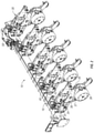
- FIG. 2 is a perspective view of a selected number of row units attached to a toolbar of an agricultural planting implement.
- FIGS. 3A and 3B are top planar and sectional views of a row unit attached to a toolbar.
- FIG. 4 is a perspective view of a single row unit.
- FIG. 5 is a perspective view of a single row unit with components removed.
- FIG. 6 is an enlarged view of a portion of a row unit showing aspects of the up/down force assembly according to the invention.
- FIG. 7 is another enlarged view of the row unit.
- FIG. 8 is yet another enlarged view of the row unit and up/down force assembly.
- FIG. 9 is still another enlarged view of the row unit and up/down force assembly showing the components in another configuration.
- FIG. 10 is a top, rear, enlarged view of the row unit and up/down force assembly.
- FIG. 11 is a top, planar, enlarged view of the row unit and up/down force assembly.
- FIG. 12 is another top and enlarged view.
- FIG. 13 is a side, enlarged view of a configuration of a row unit with a up/down force assembly.
- FIG. 14 is a view of FIG. 13 with linkage added.
- FIG. 15 is a front and side view of a row unit with an up/down force assembly according to aspects of the invention.
- FIG. 16 is perspective view of an up/down force assembly according to aspects of the invention.
- FIG. 17 is another view of an up/down force assembly according to aspects of the invention.
- FIG. 18 is a front, perspective view of the up/down force assembly of FIG. 17 .
- FIG. 19 is a schematic showing multiple row units with double acting cylinders.
- FIG. 20 is a schematic of an up and down force system including a valve at each row unit to control the up force pressure.
- FIG. 21 is a schematic of an up and down force system showing a valve at each row unit and an on/off controller for all of the rows.
- FIG. 22 is a schematic of an up and down force system showing the cylinders set to have an up force substantially at system pressure.
- FIG. 23 is a schematic of an up and down force system similar to FIG. 22 , but with one on/off controller to control for all rows.
- FIG. 24 is a schematic of an up and down force system with a valve at each row to control the up force, and also showing an accumulator at each valve block of the rows.
- FIG. 25 is a schematic of an up and down force system showing an electronic control for the up force of each cylinder.
- FIG. 1 is a perspective view of an agricultural implement.
- the agricultural implement 10 as shown in FIG. 1 is also known as a planter or planting unit.
- the agricultural planter 10 as shown in the figure is used to plant one or more types of crop in a field.
- the planter 10 may be a precision planting implement that is used to place seed with precision in a field to be most efficient and to optimize growing conditions for the planted seed types in the field.
- the implement may be generally any implement used in precision farming.
- the planter 10 as shown in FIG. 1 includes a tongue 12 including a hitch 13 at a first end thereof.
- the hitch is used generally to attach to a tractor or other tow vehicle (not shown).
- the tongue generally extends in the direction of travel of the tow vehicle.
- a toolbar 16 At an opposite end of the tongue 12 is a toolbar 16 .
- the toolbar shown in FIG. 1 extends generally perpendicular to the tongue 12 when in a planting configuration.
- the draft links 14 can be used to maintain the perpendicular configuration of the toolbar 16 relative to the tongue 12 while in a planting position.
- the tongue may be a telescoping type tongue such that the planter 10 is a front folding planter unit.
- one or more folding cylinders 21 may be connected between the toolbar 16 and the tongue 12 and can be extended or retracted to move the implement 10 between the field configuration as shown in FIG. 1 and a transport configuration, wherein generally the toolbar 16 , or parts thereof, are substantially parallel to the tongue 12 .
- the exact configuration of the planting unit 10 is not to be limiting on the invention of the disclosure herein.
- the toolbar 16 may include sections. As shown in FIG. 1 , the toolbar 16 may include a center toolbar section 17 , along with first and second wings sections or wing toolbar sections 18 , 20 extending from opposite sides of the central toolbar section 17 .
- the sections or wings 18 , 20 of the toolbar 16 allow for the planter to be folded in a frontward or upright manner for transport.
- the exact nature of the toolbar is also not to be limiting to the invention of the present disclosure.
- the toolbar could be a lift and rotate style planter, or the like.
- the wing down pressure cylinders 19 are positioned generally at the location where the wings extend from the central toolbar. The wing down pressure cylinder 19 can be used to maintain a down pressure at the wings and also to lift the wings when needed.
- one or more bulk seed tanks 22 can be included.
- the contents of both the seed and/or fertilizer tanks 22 , 24 can be delivered to individual row units via an air seed delivery system or other delivery system. This will allow the weight to be maintained generally at the locations of the tanks.
- the row units include row unit hoppers instead of utilizing bulk fill, wherein the row unit hoppers include seed and/or fertilizer.
- the weights of the hoppers at the row units also affect down force and/or down pressure.
- a plurality of wheels 28 and a plurality of fans 26 are also shown in the Figure.
- the fans 26 can be utilized to aid in the air delivery system for the hoppers, and can also provide for pressure differentials for seed meters of row units 30 .
- the wheels 28 can be used to transport the planter and to allow for easier movement through a field.
- a plurality of ground engaging members in the form of row units 30 are connected to the toolbar 16 and are utilized for performing an agricultural operation (e.g., planting, seeding, drilling, tilling, etc.).
- FIG. 2 is an enlarged view of a portion of the planter 10 .
- the figure shows a section of the toolbar 16 including a number of row units 30 attached thereto.
- a number of row units 30 will be positioned along the length of the toolbar, including the sections thereof.
- the row units can take many forms, and can be ground engaging. Examples of row units for use with the implement can be tilling units, planting units, seeders, drills, or the like. This should not be seen to be an exhaustive list, and generally and ground-engaging tools should be considered to be part of the present disclosure.
- the row units 30 could include multiple members for performing multiple agricultural operations, as well.
- the invention of the present disclosure is not to be limited to the exact configurations or to that listed herein, and is to be contemplated to include generally any type of ground engaging unit as may be known and/or used for agricultural operations.
- the row units 30 are connected to the tool bar 16 , such as via the parallel linkage, such that the row units are generally supported by the toolbar 16 (however, they will also be self-supporting in some manner when in contact with the ground or otherwise ground-engaging).
- a linkage 32 can be used to connect between a mount 31 , which is connected to the toolbar 16 , and a frame portion 36 of the row unit 30 .
- the linkage 32 as shown in the figures includes upper bars 33 and lower bars 34 .
- the four-bar linkage 32 allows for some vertical movement of the row unit 30 relative to the toolbar 16 , and vice versa, as the planter 10 moves through a field.
- additional types and/or configurations of linkages and/or other connection components to allow for such vertical movement of the row unit 30 relative to toolbar 16 can be included as part of the components disclosed herein, and are to be considered a part of the invention disclosed herein.
- the linkage may be set or configurable to prevent movement of the row unit 30 in relation to the toolbar 16 , in a temporary or permanent basis.
- the row unit 30 includes a frame 36 .
- An opener wheel or wheels 37 is connected to the frame.
- the opener wheels or other opening members are penetrated into the ground to create a furrow for depositing a seed therein.
- the figures do not disclose a seed meter or meters at the row unit 30 .
- seed meters can be utilized with a furrow opener 37 to deposit seeds in a controlled manner to allow for spacing therebetween to provide for optimal growing conditions.
- the opener sets the depth of placing the seeds, and can be controlled, as will be understood.
- One or more depth setting members can be included as part of the row unit 30 to aid and control the depth of the furrow created by the opening member 37 .
- An adjustment member 39 is also included in the row units 30 as is shown in the figures, and can be utilized to adjust the depth of the opening member 37 relative to a closing system and/or gauge member 38 . Therefore, the depth of the furrow can be adjusted either manually (e.g., mechanically) or electronically, such as manually or automatically, to provide for a consistent or chosen depth for planting the seed in a field.
- Such manners of controlling can be found in co-owned U.S. patent application Ser. No. 13/457,577, filed Apr. 27, 2012; Ser. No. 13/457,815, filed on Apr. 27, 2012; and Ser. No. 13/458,012, filed Apr. 27, 2012, with the contents of all being incorporated by reference in their entirety and for all purposes.
- aspects of the present disclosure include the addition of an up and/or down force assembly 40 (also referred to as a supplemental force assembly, cylinder assembly, actuator assembly, downforce assembly, or the like) operatively connected to the row units 30 and the toolbar 16 .
- Each row unit can be operatively connected to a force assembly 40 via the linkage 32 .
- down force assembly is commonly used herein, it is to be appreciated that the down force assembly 40 can be utilized to provide both down and up forces to the row units 30 and generally relative to the tool bar 16 .
- a down force is a net force acting generally downward or towards the field, as evidenced by the row unit, while an up force is the opposite in that it is a net force in an upward manner away from the field.
- the force applied to the row unit 30 can aid in maintaining the desired depth in the furrows created by the components of the row units 30 .
- the amount of down force may need to be increased in order to press the opening member 37 with more force into the ground such that the desired depth of furrow created by the opening member is maintained at or near the desired depth.
- the ability to provide up force by the down force assembly 40 will also allow for the row unit to be generally lifted or else relieved of its weight. This can be used when there is to be less weight than the row units themselves being needed by the field or other ground conditions, or even when the row units are to be lifted from the ground.
- the force assembly 40 which can be used for both down and up force, comprises generally the components of a double acting cylinder 48 , a manifold 44 , a control valve 46 , mounts 35 , 42 , and 52 , and a control unit 58 .
- the control valve 46 will include two control valves.
- the assembly 40 can include a down force control valve 46 a and an up force control valve 46 b .
- the down force control valve 46 a can include a solenoid or other actuable member to allow for the adjustment of the valve.
- the up force control valve 46 b can be actuable, or else can be such that the up force is generally maintained at system pressure, as will be understood herein.
- system pressure is generally whatever the pressure (e.g., hydraulic pressures) is coming in from the power/fluid source.
- the down force can be reduced to the point that the up force is variable.
- the up force control valve 46 b will be adjustable.
- these components are not limiting or required in all instances, and the assembly 40 may include fewer or more components as may be required by the intended use thereof.
- the assembly 40 may also include electrical wires, hydraulic hoses, and/or a sensing unit for determining the amount of down force being applied by the or at the row unit 30 . Still further, one or more of the components may be omitted from the assembly.
- FIG. 3B is a sectional view of a row unit 30 mounted to the toolbar 16 via the parallel linkage, as shown by the lines A-A in FIG. 3A .
- the double acting cylinder 48 is operatively attached to the tool bar 16 via a mounting unit 42 , which can include a U-bolt attached to the toolbar. Attached to a portion of the mounting unit 42 are the manifold 44 and the control valve 46 .
- the control valve may include wires 41 that are connected to a control unit 58 .
- the control unit 58 may be an intelligent control such as a processing unit, computing unit, CPU, server, or generally any other processing unit capable of receiving instructions, storing instructions, interpreting instructions, and/or providing instructions and controlling an operation of the down force assembly 40 .
- the control unit 58 can be utilized to provide commands to the control valve 46 for operating the down force assembly 40 .
- the control unit 58 may be connected, via hardwire or wirelessly, to a user interface, separate computing unit (tablet, phone, server, computer, etc.) and can be pre-programmed or otherwise capable of receiving instructions to pass along to the downforce assembly 40 .
- a double acting cylinder 48 includes a housing portion 49 and a rod 50 .
- the rod includes a piston portion (not shown) generally within the housing 49 , which can separate the housing into a first chamber 61 on the piston side of the rod, and a second chamber 62 on the rod side thereof.
- an aspect of the invention includes that the control valve 46 and manifold 44 are generally divorced from the double acting cylinder 48 such that they are not supported thereby.
- the control valve 46 and manifold 44 are not directly coupled to the cylinder 48 , and are otherwise separable by some distance therebetween.
- the manifold 44 which, based upon action of the control valve, can control the flow of a fluid, such as hydraulic fluid, can be coupled to the first and second chambers on opposite sides of the piston in the cylinder housing.
- the control valve 46 can include multiple control valves, such as a valve for down force 46 a and one for up force 46 b.
- the housing 49 of the cylinder 48 includes a first chamber 61 at the upper end of the housing and a second chamber 62 generally at a lower end of the housing and on the opposite side of the piston on the rod side thereof in the housing.
- a downforce hose 54 is connected generally between the manifold 44 and the first chamber 61 of the cylinder 48 . This could be by way of a “TEE” connection, such as that shown by numeral 46 b in FIG. 7 .
- a second hose 56 (up force hose) is connected between the manifold 44 and the second chamber 62 of the cylinder 48 . However, the second hose 56 (up force hose) could be directly connected/coupled to system pressure, wherever the system pressure source may be.
- Addition of the hydraulic fluid from the manifold via the first hose 52 to the first chamber 61 will extend the rod 50 of the cylinder 48 to provide a net down force on the row unit 30 .
- the addition of fluid creates pressure by addition of volume in the chamber, and it is the pressure that creates the net force.
- the removal of fluid from the first chamber 61 and added to the second chamber 62 such as by the hose 54 and 56 via the manifold 44 , will provide a retraction of the rod 50 relative to the housing 49 , which will constitute an up force on the row unit 30 . This up force will provide for a reduced amount of force or weight of the row unit relative to the ground.
- the control unit 58 will communicate to the control valve 46 a , which may be a solenoid, on the actuation or operation of the fluid via the manifold 44 , which will then provide the hydraulic fluid to the first or second chamber 61 , 62 of the cylinder 48 , and to provide such net up or down force thereto.
- the down force control valve 46 a is generally electrically controlled, but the up force control valve 46 b is set to provide a substantially constant up force, i.e., the up force is at system pressure as shown in FIG. 22 .
- the control unit 58 can be operated in a number of ways. For example, as shown in FIG.
- a sensor 60 is positioned at the row unit 30 and is configured to determine the amount of down force being applied via the row unit 30 .
- the sensor 60 can be a number of types of sensors, and can include strain gauges, pressure transducers, or generally any other sensing configuration to calculate and/or determine amount of force being felt by the row unit.
- the sensor can be coupled to the control unit 58 such that a change of down force sensed by the sensor 60 will activate the control unit 58 to provide a change in the down and/or up force of the assembly 40 . It is also contemplated that the sensor 60 can be in communication with a user display or graphic user interface of an operator.
- This graphic user interface can display the amount of down force being provided and being calculated by the sensor 60 such that an operator can manually communicate to the control unit 58 to adjust the amount of down force and/or up force applied by the down force assembly 40 to the row unit 30 . Therefore, it is contemplated that the control of the down force assembly 40 can be manual and/or automatic.
- the double acting cylinder 48 can be mounted to the mounting unit 42 of the force assembly 40 at a first end and can be connected to the row unit 30 , such as via the linkage 32 at the opposite or rod end 50 at a connection 52 .
- a cross bar 35 extends between the lower arms 34 of the linkage 32 .
- This cross bar 35 can be positioned generally anywhere along the length of the lower arms 34 .
- the rod 50 is connected to the cross bar 35 such that the rod 50 can be rotatably connected thereto to allow for the connection to rotate about the cross bar 35 .
- the hydraulic fluid when a down force is activated by the force assembly 40 , the hydraulic fluid will be added to the first chamber 61 of the cylinder 48 via the hose 54 through the manifold 44 , which will extend the rod 50 from the housing 49 .
- This extension will provide a force in a generally downward direction towards the cross bar 35 , which will impart more downward pressure to the row unit 30 .
- the hydraulic fluid can be provided via the hose 56 to the second chamber 62 of the cylinder 48 , which will impart a force on an underside of a piston therein, which will retract the rod 50 relative to the housing 49 .
- the downforce assembly 40 as shown and described herein will provide for both down and/or up force via the connection to the cross bar 35 .
- use of the cross bar such as that shown in FIGS. 2-5 is not the only manner of connecting the cylinder 48 to the linkage or any portion of the row unit to provide the down or up force.
- FIGS. 6-15 disclose additional aspects of the disclosure which include variations on how the force assembly 40 can be connected to the linkage 32 .
- the cylinder 48 is connected to a carriage assembly 51 .
- the carriage assembly 51 includes members which are generally U-shaped, and which are rotatably connected to the lower arms 34 of the linkage 32 .
- the operation of the cylinder and its connection to the manifold 44 in control valve 46 will be maintained, such that the control valve and manifold will control the extension in a retraction of the rod of the cylinder 48 .
- FIG. 7 shows an additional version of the carriage in which the cylinder in a similar orientation as previously disclosed herein with the carriage rotatably connected to the force assembly mount 42 and the housing 49 of the cylinder being connected to a portion of the linkage.
- the extension of the rod relative to the housing will still provide for a down force net effect on the row unit, and retraction of the rod 50 relative to the housing 49 will result in a net up force on the row unit 30 .
- the cylinder itself may not be reversed, and instead be set up so that the system is set up generally in the manner such as in previous manners. Therefore, the invention disclosed herein should not be limited to an exact configuration shown in the figures, and it is to be appreciated that generally any connection of the cylinder to the linkage and/or row unit is to be considered a part of the invention disclosed herein.
- FIGS. 16-18 disclose yet other views of the assembly 40 absent the row unit 30 and/or tool bar 16 .
- FIG. 19 shows a schematic of a force assembly according to aspects of the present disclosure.
- the figure shows the actuator connected to a tractor to control the flow of hydraulic fluid.
- the figure shows the up and down force chambers of a cylinder, which are on opposite sides of the piston of the actuator.
- the bore of the cylinder could be sized relative to the rod to provide an up force at system pressure, such as that set by the hydraulic power source. This can eliminate, mitigate, and/or reduce the need for a separate up force valve. To overcome this up force, an amount of fluid could be directed towards the upper portion of the cylinder to press the piston and rod downward, which would impart a downforce on the row unit.
- the actuator 48 includes a housing 49 and a rod 50 .
- a piston see, e.g., FIG. 19 .
- the housing 49 will have a cross-sectional area A 1 .
- the rod can have a cross-sectional area A 2 .
- Taking A 1 -A 2 will result in the net area for up force, which can be shown as A 3 .
- the net amount of downforce (F) can be found by taking the regulated pressure (PA 1 ) above the piston and subtracting the system pressure on the rod side of the piston (PA 3 ).
- the maximum downforce (Fmax) can occur when the system pressure (Psystem) is felt on the surface or cross-sectional area of the rod diameter (A 2 ).
- the minimum downforce (Fmin) occurs when the PA 1 is zero.
- Fmax, Fmin, and Psystem are known parameters, which allow you to find the ideal A 1 and A 2 for the system.
- FIGS. 20-25 show schematics of row unit supplemental force hydraulic systems according to various aspects of the disclosure.
- FIG. 20 there is shown to be a control valve at each row unit that controls the amount of up force being applied by the assembly. There is no up force main shutoff.
- FIG. 21 discloses a system wherein the control of up force is at each row, such as with a valve.
- a single on/off control valve that operates as a shutoff for all of the rows that can be activated to shut off the up force being applied thereto and/or thereat.
- the single control valve (shown as the “UP FORCE ON/OFF” in the figure) controls all of the rows.
- FIG. 22 is a schematic showing a situation wherein the up force is at system pressure, such as set by the hydraulic power source.
- One additional significant advantage of eliminating the up force valve as shown in FIG. 22 is that it reduces the hydraulic flow requirements from the power source.
- you eliminate the up force valve the fluid from the rod side is forced to the piston side and reduces the quantity from the power source that is required to fill that chamber. Oil flows to the piston side of the cylinder and reduces the hydraulic demand from the power source when the rod extends.
- FIG. 23 is a schematic with no valves at the row units to provide up force, and instead, where the up force is provided at system pressure. However, unlike FIG. 22 , there is a singular up force on/off control valve that is used to turn on or off the up force at all of the rows together.
- FIG. 24 is a schematic in which each row of the planter and including an assembly includes a control valve to control the amount of up force for the row unit. There is no singular on/off shut off controlling the rows.
- the schematic of FIG. 24 does include accumulators associated with the actuator assemblies. The accumulators are divorced from the actuators, and are situated with the valve blocks of the assemblies.
- FIG. 25 is a schematic in which there is electronic control of the up force of the row unit assemblies.
- the electronic control can be in the form of a solenoid or other electrically controlled member that controls the amount of up force at each of the row units.
- each row unit will include a force assembly 40 .
- a down force valve 46 a is controlled by a row-by-row basis.
- each row unit can have a down force control valve 46 a and an up force control valve 46 b . This is shown by the schematics of FIGS. 20, 21, 24, and 25 .
- the downforce control valve 46 a can include an electrically controlled solenoid, while the up force control valve can be set at system pressure and be configured such that the system pressure need to be overcome in order to impart a down force to the row unit by the assembly. This is shown in the figures of the present disclosure, which shows the inclusion of the separate down force solenoid valve 46 a and the up force valve 46 b.
- each row unit includes a dedicated control unit 58 or a control unit 58 that is included for a multiple of row units.
- a single control unit or box 58 controls multiple rows of a planter.
- control boxes such that each box will control multiple down force assemblies of the row units.
- the planter When the planter includes a plurality of control units, they may be electronically or wirelessly interfaced together to send to a display or interface of the operator, such that the operator is able to see the operation of each of the row units and/or each of the control units.
- an interface may be such that an operator is able to isolate a set of rows that are being controlled by a common control unit to determine the amount of down and/or up force as being apparently applied, and to determine if there are any changes that need to be made. This may also simplify trouble shooting for the down force assemblies as there are fewer control units and thus, any issues can be isolated to the row units coupled to a selected control unit.
- control unit be removed, and the system of each row unit could be connected and controlled by the tractor, such as by an operator of the tractor.
- the sensor 60 can be considered a downforce sensor to determine an amount of down force being applied to or otherwise exerted on the row unit 30 , such as between the gauge wheels and the ground.
- the sensor 60 may be connected to the gauge wheels to determine a net force being applied to the gauge wheels based upon, at least in part, the weight of the row unit 30 , the force being applied from the ground, and any up or down force being applied by an actuator or other device.
- the amount of down force sensed by the sensor can be communicated to the control box 58 , the control valve 46 , or another device such as a user display in the tow vehicle, a portable computing device (tablet, phone, handheld, etc.), or even a dedicated computing member at a location remote of the planter.
- This sensed information can be utilized to adjust or monitor the down force being applied at a particular row unit, and can be used to make such adjustments on a row by row basis, i.e., row unit independent.
- the sensor 60 as shown in the figures extends generally between an arm connected to the gauge wheels and a portion of the frame 36 of the row unit 30 .
- any sensor capable of sensing down force on the row unit e.g., gauge wheels
- any sensor capable of sensing down force on the row unit e.g., gauge wheels
- the configuration of the down force assembly as disclosed herein provides for a divorcing of the control valve and the cylinder.
- the control valve and manifold are not directly connected to the cylinder, in other words are not directly coupled thereto.
- the manifold and control valve can be mounted and supported by the toolbar, linkage, or other portion of the planting unit, and not by the row unit itself.
- the control valve can be supported by the planter frame, linkage, toolbar or generally anywhere but the row unit. This provides for numerous advantages. For example, this allows for wires that do not run through the linkage arms connecting the row units to the planter frame. It reduces clutter and provides for a cleaner look and for easier manufacturing, trouble shooting, repair, and the like. This is also true for hydraulic fluids.
- the hydraulic hoses extending from the manifold to the cylinder can be controlled in a way such that there is cleaner look and decluttering compared to that currently disclosed in the market.
- the invention as disclosed herein can provide for advantages over that presently known.
- the up force control valve can be eliminated altogether in some instances.
- the double acting cylinder can be reconfigured.
- the cylinder includes a housing and a rod.
- the rod may include a piston within the housing, as it is known. It is contemplated that if the rod side of the piston is at system pressure, this will remove the necessity for a control valve. This system pressure will maintain an up force on the row unit by the cylinder.
- a hydraulic fluid will need to be applied or added to the piston side in a manner that is to overcome the system pressure on the rod side, which will impart enough force to extend the rod relative to the housing, which will impart a force which will be applied generally downward on the row unit, to increase the down force applied thereto.
- the bore of the cylinder will be sized with respect to the rod to give the surface area that corresponds to the lift force. Therefore, this can eliminate the valve at the cylinder and can further reduce the number of components for the down force assembly as disclosed herein.
- a planter can include a down force assembly which can include a double acting cylinder which can impart a down or up force on the row unit of a planter relative to the planter frame.
- the down or up force applied thereto can be used to set and/or maintain a desired depth of furrow created by a component of the row unit and can be individually addressed for each row unit along the length of the tool bar of the planter frame.
- the advantages of divorcing the valve and manifold from the double acting cylinder can provide a cleaner look for decluttering components on the planter, which will reduce the complications associated with many planting implements. This will still provide the control, which can be manual or automatic for changing or else setting the amount of force applied in either an up or down manner to the row unit via the assembly and relative to the tool bar, which will provide for additional advantages.
Abstract
Description
Claims (20)
Priority Applications (1)
| Application Number | Priority Date | Filing Date | Title |
|---|---|---|---|
| US16/047,236 US11224153B2 (en) | 2017-07-28 | 2018-07-27 | Agricultural implement and row units including double acting actuator systems, methods, and apparatus |
Applications Claiming Priority (3)
| Application Number | Priority Date | Filing Date | Title |
|---|---|---|---|
| US201762538309P | 2017-07-28 | 2017-07-28 | |
| US201762542344P | 2017-08-08 | 2017-08-08 | |
| US16/047,236 US11224153B2 (en) | 2017-07-28 | 2018-07-27 | Agricultural implement and row units including double acting actuator systems, methods, and apparatus |
Publications (2)
| Publication Number | Publication Date |
|---|---|
| US20190029165A1 US20190029165A1 (en) | 2019-01-31 |
| US11224153B2 true US11224153B2 (en) | 2022-01-18 |
Family
ID=65040879
Family Applications (1)
| Application Number | Title | Priority Date | Filing Date |
|---|---|---|---|
| US16/047,236 Active 2040-02-04 US11224153B2 (en) | 2017-07-28 | 2018-07-27 | Agricultural implement and row units including double acting actuator systems, methods, and apparatus |
Country Status (5)
| Country | Link |
|---|---|
| US (1) | US11224153B2 (en) |
| EP (1) | EP3637976A1 (en) |
| RU (1) | RU2739383C1 (en) |
| UA (1) | UA127761C2 (en) |
| WO (1) | WO2019023581A1 (en) |
Families Citing this family (23)
| Publication number | Priority date | Publication date | Assignee | Title |
|---|---|---|---|---|
| CA2837715C (en) | 2011-06-03 | 2020-07-21 | Precision Planting Llc | Agricultural toolbar apparatus, systems and methods |
| US11246254B1 (en) | 2018-08-22 | 2022-02-15 | Parker-Hannifin Corporation | Negative downforce system for ground engaging machinery |
| US11259455B2 (en) | 2019-04-18 | 2022-03-01 | Cnh Industrial America Llc | System and method for controlling the operation of a residue removal device of a seed-planting implement based on a residue characteristic of the field |
| US11266060B2 (en) * | 2019-06-06 | 2022-03-08 | Cnh Industrial America Llc | System and method for controlling the operation of a seed-planting implement based on cover crop density |
| US11490558B2 (en) | 2019-12-24 | 2022-11-08 | Cnh Industrial America Llc | Particle delivery system of an agricultural row unit |
| US11523555B2 (en) | 2019-12-24 | 2022-12-13 | Cnh Industrial America Llc | Particle delivery system of an agricultural row unit |
| US11516958B2 (en) | 2019-12-24 | 2022-12-06 | Cnh Industrial America Llc | Particle delivery system of an agricultural row unit |
| US11596095B2 (en) | 2019-12-24 | 2023-03-07 | Cnh Industrial America Llc | Particle delivery system of an agricultural row unit |
| US11582899B2 (en) | 2019-12-24 | 2023-02-21 | Cnh Industrial America Llc | Particle delivery system of an agricultural row unit |
| US11564344B2 (en) | 2019-12-24 | 2023-01-31 | Cnh Industrial America Llc | Particle delivery system of an agricultural row unit |
| US11589500B2 (en) | 2019-12-24 | 2023-02-28 | Cnh Industrial America Llc | Particle delivery system of an agricultural row unit |
| US11523556B2 (en) | 2019-12-24 | 2022-12-13 | Cnh Industrial America Llc | Particle delivery system of an agricultural row unit |
| US11553638B2 (en) | 2019-12-24 | 2023-01-17 | Cnh Industrial America Llc | Particle delivery system of an agricultural row unit |
| US11483963B2 (en) | 2019-12-24 | 2022-11-01 | Cnh Industrial America Llc | Particle delivery system of an agricultural row unit |
| US11564346B2 (en) | 2019-12-24 | 2023-01-31 | Cnh Industrial America Llc | Particle delivery system of an agricultural row unit |
| US11553639B2 (en) | 2019-12-24 | 2023-01-17 | Cnh Industrial America Llc | Particle delivery system of an agricultural row unit |
| US11653585B2 (en) * | 2020-06-05 | 2023-05-23 | Deere & Company | Implement variable downforce control |
| SE2150874A1 (en) * | 2021-07-05 | 2023-01-06 | Vaederstad Holding Ab | Creation of agricultural tramline patterns |
| SE544832C2 (en) * | 2021-07-05 | 2022-12-06 | Vaederstad Holding Ab | Down force control and method for down force control in an agricultural implement |
| SE2150873A1 (en) * | 2021-07-05 | 2023-01-06 | Vaederstad Holding Ab | Selective raising of ground engaging tools |
| USD980877S1 (en) | 2021-07-23 | 2023-03-14 | Cnh Industrial America Llc | Agricultural planter |
| USD980878S1 (en) | 2021-07-23 | 2023-03-14 | Cnh Industrial America Llc | Agricultural planter |
| USD980879S1 (en) | 2021-07-23 | 2023-03-14 | Cnh Industrial America Llc | Agricultural planter |
Citations (119)
| Publication number | Priority date | Publication date | Assignee | Title |
|---|---|---|---|---|
| SU502622A1 (en) | 1974-06-03 | 1976-02-15 | Латвийский Научно-Исследовательский Институт Механизации И Электрификации Сельского Хозяйства | Se lka |
| US4176721A (en) | 1976-11-30 | 1979-12-04 | Kep Enterprises | Depth control for ground working agricultural implements |
| US5524560A (en) | 1994-12-09 | 1996-06-11 | The United States Of America As Represented By The Department Of Agriculture | System for controlling vertical displacement of agricultural implements into the soil |
| EP1052890A1 (en) | 1998-02-04 | 2000-11-22 | Amazonen-Werke H. Dreyer GmbH & Co. KG | Sowing device |
| US6389999B1 (en) | 2001-11-02 | 2002-05-21 | Dennis Duello | Dynamic controller of excess downpressure for surface engaging implement |
| US20030019408A1 (en) | 2001-02-28 | 2003-01-30 | Clyde Fraisse | Method for prescribing site-specific fertilizer application in agricultural fields |
| US20030101626A1 (en) | 2001-12-04 | 2003-06-05 | Johnson Andrew Harold | Air spring actuator weight transfer apparatus |
| US6827029B1 (en) | 2003-11-04 | 2004-12-07 | Cnh America Llc | Method and apparatus for automatically maintaining seed trench depth during seed planting operations |
| US20050120928A1 (en) | 2003-12-09 | 2005-06-09 | Horn Rodney S. | Seed planter including vertical positioner with locking member |
| US20050155536A1 (en) | 2004-01-16 | 2005-07-21 | Wendte Keith W. | Tandem gauge wheel assembly for planting unit |
| US20060065412A1 (en) | 2004-09-28 | 2006-03-30 | Bauer Mark A | Zone tillage tool and method |
| US7028554B2 (en) | 2003-07-11 | 2006-04-18 | Deere & Company | Instrumented deep tillage implement |
| US20060131040A1 (en) | 2004-12-16 | 2006-06-22 | Husco International, Inc. | Configurable hydraulic system for agricultural tractor and implement combination |
| US20060213407A1 (en) | 2005-01-07 | 2006-09-28 | Precision Planting, Inc. | Planter meter suspension system and method of improving seed spacing |
| US20080011208A1 (en) | 2006-07-14 | 2008-01-17 | Martin Howard D | Apparatus for planter depth monitoring |
| EP1594355B1 (en) | 2003-02-20 | 2008-04-16 | Amazonen-Werke H. Dreyer GmbH & Co. KG | Agricultural device |
| US7360495B1 (en) | 2006-12-18 | 2008-04-22 | Howard D. Martin | Method for planter depth monitoring |
| US7401561B1 (en) | 2007-08-16 | 2008-07-22 | Kurz Clare D | Suspension system for a row crop planter unit |
| EP1974596A1 (en) | 2007-03-26 | 2008-10-01 | Horsch Maschinen GmbH | Seed coulter assembly |
| EA011070B1 (en) | 2005-11-04 | 2008-12-30 | Амазонен-Верке Х. Драйер Гмбх Унд Ко. Кг | Seeding machine |
| US20090090521A1 (en) | 2001-07-30 | 2009-04-09 | Caterpillar Inc. | Hydraulic disc/harrow apparatus, system and method for using the same |
| US20090175235A1 (en) | 1999-05-21 | 2009-07-09 | Wi-Lan, Inc. | Method and system for adaptively obtaining bandwidth allocation requests |
| US20090266279A1 (en) | 2008-04-28 | 2009-10-29 | Jeff Dillman | Planter assembly with selectively actuated output |
| WO2009134144A1 (en) | 2008-04-29 | 2009-11-05 | Agromiljø As | Depth control device for a coulter |
| WO2009149473A2 (en) | 2008-06-06 | 2009-12-10 | Martin R Steven | Adjustable row cleaner |
| WO2010056834A1 (en) | 2008-11-13 | 2010-05-20 | Deere & Company | Seed sensor system and method for improved seed count and seed spacing |
| US20100180695A1 (en) | 2007-01-08 | 2010-07-22 | Precision Planting, Inc. | Load sensing pin |
| US20100198529A1 (en) | 2007-09-26 | 2010-08-05 | Precision Planting, Inc. | System and method for determining proper downforce for a planter row unit |
| US20110005784A1 (en) | 2009-07-09 | 2011-01-13 | Landoll Donald R | Air spring down-pressure system for implement |
| US20110120357A1 (en) | 2009-11-24 | 2011-05-26 | Schilling Robin B | Down Pressure Adjustment Assembly For A Disc Opener Of An Agricultural Implement |
| EP2353354A1 (en) | 2010-01-29 | 2011-08-10 | Lemken GmbH & Co. KG | Double disc coulter with depth guide roller |
| US20110228870A1 (en) | 2006-02-28 | 2011-09-22 | Rotani, Inc. | Method and Apparatus for Overlapping MIMO Physical Sectors |
| WO2011161140A1 (en) | 2010-06-22 | 2011-12-29 | Cnh Belgium N.V. | Down pressure adjustment device and method for use with a disc opener assembly of an agricultural implement |
| US20120017813A1 (en) | 2009-04-30 | 2012-01-26 | L & B Manufacturing, Inc. | Soil Tilling and Planting Implement |
| US20120060730A1 (en) * | 2010-09-15 | 2012-03-15 | Dawn Equipment Company | Row unit for agricultural implement |
| US20120151910A1 (en) * | 2010-12-16 | 2012-06-21 | Precision Planting, Inc. | Variable pressure control system for dual acting actuators |
| RU2454058C1 (en) | 2011-02-28 | 2012-06-27 | Государственное научное учреждение Всероссийский научно-исследовательский институт механизации сельского хозяйства (ГНУ ВИМ Россельхозакадемии) | Fertiliser dispenser for precision farming |
| US20120186503A1 (en) * | 2011-01-26 | 2012-07-26 | Precision Planting, Inc. | Dynamic supplemental downforce control system for planter row units |
| EP2497348A1 (en) | 2011-03-08 | 2012-09-12 | Deere & Company | Product distribution apparatus and method of controlling |
| US8275525B2 (en) | 2010-06-22 | 2012-09-25 | Cnh Canada, Ltd. | Automatic down pressure adjustment system for set of ganged disc openers |
| WO2012149367A1 (en) | 2011-04-27 | 2012-11-01 | Kinze Manufacturing, Inc. | Down and/or up force adjustment system |
| WO2012149415A1 (en) | 2011-04-27 | 2012-11-01 | Kinze Manufacturing, Inc. | Remote adjustment of a row unit of an agricultural device |
| US8327780B2 (en) | 2009-10-16 | 2012-12-11 | Dawn Equipment Company | Agricultural implement having fluid delivery features |
| US8359988B2 (en) | 2007-07-24 | 2013-01-29 | Dawn Equipment Company | Agricultural tillage device |
| EP2554036A1 (en) | 2011-08-01 | 2013-02-06 | Deere & Company | A supplemental down force system and ground working implement with same |
| US20130032362A1 (en) | 2011-08-01 | 2013-02-07 | Rylander David J | Supplemental down force system for a ground working implement with variable row unit grouping and implement with same |
| US20130046418A1 (en) | 2011-08-17 | 2013-02-21 | Noel Wayne Anderson | V-foot tire management at fleet level |
| WO2013025898A1 (en) | 2011-08-17 | 2013-02-21 | Deere & Company | Vehicle soil pressure management based on topography |
| WO2013049198A1 (en) | 2011-09-27 | 2013-04-04 | Precision Planting Llc | Seed delivery apparatus, systems, and methods |
| US8448717B2 (en) | 2010-08-30 | 2013-05-28 | Cnh America Llc | Manual backup system for controlling fluid flow to cylinders within an agricultural implement |
| US8469114B1 (en) | 2011-12-21 | 2013-06-25 | Deere & Company | Towed implement with a steering system having both wheel assemblies and coulters |
| US8522889B2 (en) | 2010-08-30 | 2013-09-03 | Cnh America Llc | Agricultural implement with combined down force and depth control |
| US20130247802A1 (en) | 2012-03-23 | 2013-09-26 | Truax Company Inc. | Versatile no-till seed planter |
| US8544398B2 (en) | 2010-09-15 | 2013-10-01 | Dawn Equipment Company | Hydraulic down pressure control system for closing wheels of an agricultural implement |
| US8573319B1 (en) | 2012-06-20 | 2013-11-05 | Deere & Company | Position and pressure depth control system for an agricultural implement |
| US20140000919A1 (en) | 2012-06-28 | 2014-01-02 | Kinze Manufacturing, Inc. | Weight distribution system for seed planters and product applicators |
| US8636077B2 (en) | 2012-05-22 | 2014-01-28 | Dawn Equipment Company | Agricultural tool with structural housing for hydraulic actuator |
| US20140026748A1 (en) * | 2012-07-25 | 2014-01-30 | Precision Planting Llc | Integrated implement downforce control systems, methods, and apparatus |
| WO2014026183A2 (en) | 2012-08-10 | 2014-02-13 | Precision Planting Llc | Systems and methods for control, monitoring and mapping of agricultural applications |
| CN103640815A (en) | 2013-12-03 | 2014-03-19 | Tcl家用电器(合肥)有限公司 | Compressor installation plate, refrigerator, base cushion used for refrigerator and packaging box used for refrigerator |
| EP2717667A2 (en) | 2011-06-10 | 2014-04-16 | Great Plains Manufacturing, Inc. | Agricultural implement having hopper weighing system |
| US20140116735A1 (en) * | 2010-09-15 | 2014-05-01 | Dawn Equipment Compnay | Agricultural Systems |
| WO2014066650A1 (en) | 2012-10-24 | 2014-05-01 | Precision Planting Llc | Agricultural trench closing systems, methods, and apparatus |
| US8763713B2 (en) | 2012-01-27 | 2014-07-01 | Dawn Equipment Company | Agricultural implement with automatic down pressure control |
| US8776702B2 (en) | 2010-09-15 | 2014-07-15 | Dawn Equipment Company | Hydraulic down pressure control system for an agricultural implement |
| US8794344B2 (en) | 2012-09-06 | 2014-08-05 | Cnh Industrial America Llc | Down pressure control system for an agricultural implement |
| USRE45091E1 (en) | 2008-12-01 | 2014-08-26 | Dawn Equipment Company | Row-clearing unit for agricultural implement |
| US8827001B2 (en) | 2012-01-17 | 2014-09-09 | Cnh Industrial America Llc | Soil monitoring system |
| US8826836B2 (en) | 2012-08-24 | 2014-09-09 | L & B Manufacturing, Inc. | Row treating unit for agriculture implement |
| US20140277959A1 (en) | 2013-03-15 | 2014-09-18 | Jesse L. Wagers | Multi-seed planter control system and method for the same |
| US8863857B2 (en) | 2011-02-23 | 2014-10-21 | Dawn Equipment Company | Row unit for agricultural implement |
| US8910581B2 (en) | 2012-07-25 | 2014-12-16 | Dawn Equipment Company | Side dressing fertilizer coulter |
| US8910582B2 (en) | 2011-04-11 | 2014-12-16 | Deere & Company | Row unit for a seeding machine having active downforce control for the closing wheels |
| US8935986B2 (en) | 2011-04-27 | 2015-01-20 | Kinze Manufacturing, Inc. | Agricultural devices, systems, and methods for determining soil and seed characteristics and analyzing the same |
| WO2015031840A1 (en) | 2013-08-30 | 2015-03-05 | Precision Planting Llc | Seed delivery apparatus, systems, and methods |
| US8985232B2 (en) | 2012-08-20 | 2015-03-24 | Dawn Equipment Company | Agricultural apparatus for sensing and providing feedback of soil property changes in real time |
| CA2866045A1 (en) | 2013-12-11 | 2015-06-11 | Cnh Industrial Canada, Ltd. | Remote leveling of tillage implements using three way valves |
| CA2866049A1 (en) | 2013-12-11 | 2015-06-11 | Cnh Industrial Canada, Ltd. | Remote leveling of tillage implements |
| US9055712B2 (en) | 2010-09-15 | 2015-06-16 | Dawn Equipment Company | Agricultural apparatus with integrated controller for a row unit |
| US9107338B2 (en) | 2010-09-15 | 2015-08-18 | Dawn Equipment Company | Agricultural systems |
| US9107337B2 (en) | 2012-08-20 | 2015-08-18 | Dawn Equipment Company | Agricultural apparatus for sensing and providing feedback of soil property changes in real time |
| US9137939B2 (en) | 2013-03-15 | 2015-09-22 | Alan E. Winick | Electric adjusting apparatus for row cleaners |
| US20150264857A1 (en) | 2014-03-21 | 2015-09-24 | Kinze Manufacturing, Inc. | Apparatuses, methods, and systems for providing down force for an agricultural implement |
| US9148989B2 (en) | 2013-02-12 | 2015-10-06 | L & B Manufacturing, Inc. | Row treating unit for agriculture implement |
| US20150289438A1 (en) | 2012-10-24 | 2015-10-15 | Precision Planting Llc | Agricultural trench depth sensing systems, methods, and apparatus |
| US9192091B2 (en) | 2013-02-01 | 2015-11-24 | Dawn Equipment Company | Agricultural apparatus with hybrid single-disk, double-disk coulter arrangement |
| CN105103722A (en) | 2015-08-12 | 2015-12-02 | 北京农业信息技术研究中心 | Seeding device and control method capable of adjusting depth of seeding |
| US9215838B2 (en) | 2013-02-01 | 2015-12-22 | Dawn Equipment Company | Agricultural apparatus with hybrid single-disk, double-disk coulter arrangement |
| US9226440B2 (en) | 2010-09-15 | 2016-01-05 | Dawn Equipment Company | Agricultural apparatus with hydraulic cylinder and manifold for a row unit |
| US9241438B2 (en) | 2014-02-05 | 2016-01-26 | Dawn Equipment Company | Agricultural system for field preparation |
| US20160044857A1 (en) | 2014-08-14 | 2016-02-18 | Deere & Company | Agricultural implement and attachment with down pressure control system |
| US9271437B2 (en) | 2011-07-01 | 2016-03-01 | Charles H. Martin | Agricultural field preparation device |
| US9282689B2 (en) | 2009-04-30 | 2016-03-15 | L & B Manufacturing, Inc. | Soil tilling and planting implement |
| US9288937B2 (en) | 2011-08-05 | 2016-03-22 | Precision Planting Llc | Apparatus, systems and methods for row unit downforce control |
| US9307690B2 (en) | 2012-06-14 | 2016-04-12 | Dawn Equipment Company | Forged toothed wheel for a row crop planter |
| US20160128265A1 (en) | 2014-11-07 | 2016-05-12 | Dawn Equipment Company | Agricultural System |
| US9462744B2 (en) | 2013-03-05 | 2016-10-11 | John D. Isaacson | Agricultural tool with electronically controlled downpressure system |
| US9462740B2 (en) | 2014-06-19 | 2016-10-11 | Cnh Industrial America Llc | Long distance electronic load sense signal communication for implement control |
| US9485900B2 (en) | 2014-09-29 | 2016-11-08 | Deere & Company | Agricultural implement plug detection |
| US20160338257A1 (en) * | 2013-11-08 | 2016-11-24 | Precision Planting Llc | Implement weight management systems, methods, and apparatus |
| US9511633B2 (en) | 2011-08-17 | 2016-12-06 | Deere & Company | Soil compaction management and reporting |
| US20170094889A1 (en) | 2015-10-02 | 2017-04-06 | Deere & Company | Soil characteristic sensors on ground-engaging elements of a planting machine |
| US9615497B2 (en) | 2014-02-21 | 2017-04-11 | Dawn Equipment Company | Modular autonomous farm vehicle |
| US9668398B2 (en) | 2014-02-05 | 2017-06-06 | Dawn Equipment Company | Agricultural system for field preparation |
| US9675004B2 (en) | 2015-09-30 | 2017-06-13 | Deere & Company | Soil moisture-based planter downforce control |
| US9693496B2 (en) | 2015-09-30 | 2017-07-04 | Deere & Company | Agricultural planting depth sensor |
| US20170215329A1 (en) * | 2016-01-29 | 2017-08-03 | CNH Industrial America, LLC | System for controlling the supply of hydraulic fluid to a work vehicle implement |
| US9743578B2 (en) | 2011-04-27 | 2017-08-29 | Kinze Manufacturing, Inc. | Agricultural devices, systems, and methods for determining soil and seed characteristics and analyzing the same |
| US9801332B2 (en) | 2015-09-30 | 2017-10-31 | Deere & Company | System and method for consistent depth seeding to moisture |
| WO2017197274A1 (en) | 2016-05-13 | 2017-11-16 | Precision Planting Llc | Seed trench closing sensors |
| US9826677B2 (en) | 2014-12-16 | 2017-11-28 | Cnh Industrial Canada, Ltd. | Seed implement incorporating a down pressure sensing and adjustment system |
| US9848522B2 (en) | 2014-11-07 | 2017-12-26 | Dawn Equipment Company | Agricultural system |
| EP3259972A1 (en) | 2012-07-25 | 2017-12-27 | Precision Planting LLC | System and method for multi-row agricultural implement control and monitoring |
| US9943027B2 (en) | 2013-03-14 | 2018-04-17 | Precision Planting Llc | Systems, methods, and apparatus for agricultural implement trench depth control and soil monitoring |
| WO2018075788A1 (en) | 2016-10-20 | 2018-04-26 | Precision Planting Llc | Air seeder press wheel and closing wheel force control |
| US10010025B2 (en) | 2016-01-29 | 2018-07-03 | Cnh Industrial America Llc | Opener attachment for an agricultural row unit |
| US20200154627A1 (en) * | 2017-05-26 | 2020-05-21 | Precision Planting Llc | Method to prevent drift of an agricultural implement |
| US20200315081A1 (en) * | 2017-07-03 | 2020-10-08 | Precision Planting, Llc | Air seeder downforce control |
| US20200337207A1 (en) * | 2019-04-26 | 2020-10-29 | Cnh Industrial America Llc | System and method for controlling downforce on a multi-wing agricultural implement |
-
2018
- 2018-07-27 EP EP18837317.9A patent/EP3637976A1/en not_active Withdrawn
- 2018-07-27 WO PCT/US2018/044098 patent/WO2019023581A1/en unknown
- 2018-07-27 RU RU2020108449A patent/RU2739383C1/en active
- 2018-07-27 US US16/047,236 patent/US11224153B2/en active Active
- 2018-07-27 UA UAA202001310A patent/UA127761C2/en unknown
Patent Citations (128)
| Publication number | Priority date | Publication date | Assignee | Title |
|---|---|---|---|---|
| SU502622A1 (en) | 1974-06-03 | 1976-02-15 | Латвийский Научно-Исследовательский Институт Механизации И Электрификации Сельского Хозяйства | Se lka |
| US4176721A (en) | 1976-11-30 | 1979-12-04 | Kep Enterprises | Depth control for ground working agricultural implements |
| US5524560A (en) | 1994-12-09 | 1996-06-11 | The United States Of America As Represented By The Department Of Agriculture | System for controlling vertical displacement of agricultural implements into the soil |
| EP1052890A1 (en) | 1998-02-04 | 2000-11-22 | Amazonen-Werke H. Dreyer GmbH & Co. KG | Sowing device |
| US20090175235A1 (en) | 1999-05-21 | 2009-07-09 | Wi-Lan, Inc. | Method and system for adaptively obtaining bandwidth allocation requests |
| US20030019408A1 (en) | 2001-02-28 | 2003-01-30 | Clyde Fraisse | Method for prescribing site-specific fertilizer application in agricultural fields |
| US20090090521A1 (en) | 2001-07-30 | 2009-04-09 | Caterpillar Inc. | Hydraulic disc/harrow apparatus, system and method for using the same |
| US6389999B1 (en) | 2001-11-02 | 2002-05-21 | Dennis Duello | Dynamic controller of excess downpressure for surface engaging implement |
| US20030101626A1 (en) | 2001-12-04 | 2003-06-05 | Johnson Andrew Harold | Air spring actuator weight transfer apparatus |
| EP1594355B1 (en) | 2003-02-20 | 2008-04-16 | Amazonen-Werke H. Dreyer GmbH & Co. KG | Agricultural device |
| US7028554B2 (en) | 2003-07-11 | 2006-04-18 | Deere & Company | Instrumented deep tillage implement |
| US6827029B1 (en) | 2003-11-04 | 2004-12-07 | Cnh America Llc | Method and apparatus for automatically maintaining seed trench depth during seed planting operations |
| US20050120928A1 (en) | 2003-12-09 | 2005-06-09 | Horn Rodney S. | Seed planter including vertical positioner with locking member |
| US20050155536A1 (en) | 2004-01-16 | 2005-07-21 | Wendte Keith W. | Tandem gauge wheel assembly for planting unit |
| US20060065412A1 (en) | 2004-09-28 | 2006-03-30 | Bauer Mark A | Zone tillage tool and method |
| US20060131040A1 (en) | 2004-12-16 | 2006-06-22 | Husco International, Inc. | Configurable hydraulic system for agricultural tractor and implement combination |
| US20060213407A1 (en) | 2005-01-07 | 2006-09-28 | Precision Planting, Inc. | Planter meter suspension system and method of improving seed spacing |
| EA011070B1 (en) | 2005-11-04 | 2008-12-30 | Амазонен-Верке Х. Драйер Гмбх Унд Ко. Кг | Seeding machine |
| US20110228870A1 (en) | 2006-02-28 | 2011-09-22 | Rotani, Inc. | Method and Apparatus for Overlapping MIMO Physical Sectors |
| US20080011208A1 (en) | 2006-07-14 | 2008-01-17 | Martin Howard D | Apparatus for planter depth monitoring |
| US7360495B1 (en) | 2006-12-18 | 2008-04-22 | Howard D. Martin | Method for planter depth monitoring |
| US20100180695A1 (en) | 2007-01-08 | 2010-07-22 | Precision Planting, Inc. | Load sensing pin |
| EP1974596A1 (en) | 2007-03-26 | 2008-10-01 | Horsch Maschinen GmbH | Seed coulter assembly |
| US8359988B2 (en) | 2007-07-24 | 2013-01-29 | Dawn Equipment Company | Agricultural tillage device |
| US7401561B1 (en) | 2007-08-16 | 2008-07-22 | Kurz Clare D | Suspension system for a row crop planter unit |
| US20100198529A1 (en) | 2007-09-26 | 2010-08-05 | Precision Planting, Inc. | System and method for determining proper downforce for a planter row unit |
| US20090266279A1 (en) | 2008-04-28 | 2009-10-29 | Jeff Dillman | Planter assembly with selectively actuated output |
| WO2009134144A1 (en) | 2008-04-29 | 2009-11-05 | Agromiljø As | Depth control device for a coulter |
| WO2009149473A2 (en) | 2008-06-06 | 2009-12-10 | Martin R Steven | Adjustable row cleaner |
| WO2010056834A1 (en) | 2008-11-13 | 2010-05-20 | Deere & Company | Seed sensor system and method for improved seed count and seed spacing |
| USRE45091E1 (en) | 2008-12-01 | 2014-08-26 | Dawn Equipment Company | Row-clearing unit for agricultural implement |
| US20120017813A1 (en) | 2009-04-30 | 2012-01-26 | L & B Manufacturing, Inc. | Soil Tilling and Planting Implement |
| US9282689B2 (en) | 2009-04-30 | 2016-03-15 | L & B Manufacturing, Inc. | Soil tilling and planting implement |
| US20110005784A1 (en) | 2009-07-09 | 2011-01-13 | Landoll Donald R | Air spring down-pressure system for implement |
| US8327780B2 (en) | 2009-10-16 | 2012-12-11 | Dawn Equipment Company | Agricultural implement having fluid delivery features |
| US20110120357A1 (en) | 2009-11-24 | 2011-05-26 | Schilling Robin B | Down Pressure Adjustment Assembly For A Disc Opener Of An Agricultural Implement |
| EP2353354A1 (en) | 2010-01-29 | 2011-08-10 | Lemken GmbH & Co. KG | Double disc coulter with depth guide roller |
| WO2011161140A1 (en) | 2010-06-22 | 2011-12-29 | Cnh Belgium N.V. | Down pressure adjustment device and method for use with a disc opener assembly of an agricultural implement |
| US8275525B2 (en) | 2010-06-22 | 2012-09-25 | Cnh Canada, Ltd. | Automatic down pressure adjustment system for set of ganged disc openers |
| US8522889B2 (en) | 2010-08-30 | 2013-09-03 | Cnh America Llc | Agricultural implement with combined down force and depth control |
| US8448717B2 (en) | 2010-08-30 | 2013-05-28 | Cnh America Llc | Manual backup system for controlling fluid flow to cylinders within an agricultural implement |
| US9232687B2 (en) | 2010-09-15 | 2016-01-12 | Dawn Equipment Company | Agricultural systems |
| US9055712B2 (en) | 2010-09-15 | 2015-06-16 | Dawn Equipment Company | Agricultural apparatus with integrated controller for a row unit |
| US8776702B2 (en) | 2010-09-15 | 2014-07-15 | Dawn Equipment Company | Hydraulic down pressure control system for an agricultural implement |
| US8544397B2 (en) | 2010-09-15 | 2013-10-01 | Dawn Equipment Company | Row unit for agricultural implement |
| US20120060730A1 (en) * | 2010-09-15 | 2012-03-15 | Dawn Equipment Company | Row unit for agricultural implement |
| US8544398B2 (en) | 2010-09-15 | 2013-10-01 | Dawn Equipment Company | Hydraulic down pressure control system for closing wheels of an agricultural implement |
| US9226440B2 (en) | 2010-09-15 | 2016-01-05 | Dawn Equipment Company | Agricultural apparatus with hydraulic cylinder and manifold for a row unit |
| US20150373901A1 (en) * | 2010-09-15 | 2015-12-31 | Dawn Equipment Company | Row Unit For Agricultural Implement |
| US20140116735A1 (en) * | 2010-09-15 | 2014-05-01 | Dawn Equipment Compnay | Agricultural Systems |
| US9107338B2 (en) | 2010-09-15 | 2015-08-18 | Dawn Equipment Company | Agricultural systems |
| US20120151910A1 (en) * | 2010-12-16 | 2012-06-21 | Precision Planting, Inc. | Variable pressure control system for dual acting actuators |
| US8550020B2 (en) | 2010-12-16 | 2013-10-08 | Precision Planting Llc | Variable pressure control system for dual acting actuators |
| US8634992B2 (en) | 2011-01-26 | 2014-01-21 | Precision Planting Llc | Dynamic supplemental downforce control system for planter row units |
| US20120186503A1 (en) * | 2011-01-26 | 2012-07-26 | Precision Planting, Inc. | Dynamic supplemental downforce control system for planter row units |
| US8863857B2 (en) | 2011-02-23 | 2014-10-21 | Dawn Equipment Company | Row unit for agricultural implement |
| RU2454058C1 (en) | 2011-02-28 | 2012-06-27 | Государственное научное учреждение Всероссийский научно-исследовательский институт механизации сельского хозяйства (ГНУ ВИМ Россельхозакадемии) | Fertiliser dispenser for precision farming |
| EP2497348A1 (en) | 2011-03-08 | 2012-09-12 | Deere & Company | Product distribution apparatus and method of controlling |
| US8910582B2 (en) | 2011-04-11 | 2014-12-16 | Deere & Company | Row unit for a seeding machine having active downforce control for the closing wheels |
| US8909436B2 (en) | 2011-04-27 | 2014-12-09 | Kinze Manufacturing, Inc. | Remote adjustment of a row unit of an agricultural device |
| US8935986B2 (en) | 2011-04-27 | 2015-01-20 | Kinze Manufacturing, Inc. | Agricultural devices, systems, and methods for determining soil and seed characteristics and analyzing the same |
| US9743578B2 (en) | 2011-04-27 | 2017-08-29 | Kinze Manufacturing, Inc. | Agricultural devices, systems, and methods for determining soil and seed characteristics and analyzing the same |
| WO2012149367A1 (en) | 2011-04-27 | 2012-11-01 | Kinze Manufacturing, Inc. | Down and/or up force adjustment system |
| WO2012149415A1 (en) | 2011-04-27 | 2012-11-01 | Kinze Manufacturing, Inc. | Remote adjustment of a row unit of an agricultural device |
| EP2717667A2 (en) | 2011-06-10 | 2014-04-16 | Great Plains Manufacturing, Inc. | Agricultural implement having hopper weighing system |
| US9271437B2 (en) | 2011-07-01 | 2016-03-01 | Charles H. Martin | Agricultural field preparation device |
| EP2554036A1 (en) | 2011-08-01 | 2013-02-06 | Deere & Company | A supplemental down force system and ground working implement with same |
| US20130032362A1 (en) | 2011-08-01 | 2013-02-07 | Rylander David J | Supplemental down force system for a ground working implement with variable row unit grouping and implement with same |
| US9288937B2 (en) | 2011-08-05 | 2016-03-22 | Precision Planting Llc | Apparatus, systems and methods for row unit downforce control |
| US20130046418A1 (en) | 2011-08-17 | 2013-02-21 | Noel Wayne Anderson | V-foot tire management at fleet level |
| WO2013025898A1 (en) | 2011-08-17 | 2013-02-21 | Deere & Company | Vehicle soil pressure management based on topography |
| US8843269B2 (en) | 2011-08-17 | 2014-09-23 | Deere & Company | Vehicle soil pressure management based on topography |
| US9511633B2 (en) | 2011-08-17 | 2016-12-06 | Deere & Company | Soil compaction management and reporting |
| WO2013049198A1 (en) | 2011-09-27 | 2013-04-04 | Precision Planting Llc | Seed delivery apparatus, systems, and methods |
| US8469114B1 (en) | 2011-12-21 | 2013-06-25 | Deere & Company | Towed implement with a steering system having both wheel assemblies and coulters |
| US8827001B2 (en) | 2012-01-17 | 2014-09-09 | Cnh Industrial America Llc | Soil monitoring system |
| US8763713B2 (en) | 2012-01-27 | 2014-07-01 | Dawn Equipment Company | Agricultural implement with automatic down pressure control |
| US20130247802A1 (en) | 2012-03-23 | 2013-09-26 | Truax Company Inc. | Versatile no-till seed planter |
| US8636077B2 (en) | 2012-05-22 | 2014-01-28 | Dawn Equipment Company | Agricultural tool with structural housing for hydraulic actuator |
| US9307690B2 (en) | 2012-06-14 | 2016-04-12 | Dawn Equipment Company | Forged toothed wheel for a row crop planter |
| US8573319B1 (en) | 2012-06-20 | 2013-11-05 | Deere & Company | Position and pressure depth control system for an agricultural implement |
| US20140000919A1 (en) | 2012-06-28 | 2014-01-02 | Kinze Manufacturing, Inc. | Weight distribution system for seed planters and product applicators |
| EP3259972A1 (en) | 2012-07-25 | 2017-12-27 | Precision Planting LLC | System and method for multi-row agricultural implement control and monitoring |
| US20140026748A1 (en) * | 2012-07-25 | 2014-01-30 | Precision Planting Llc | Integrated implement downforce control systems, methods, and apparatus |
| US8910581B2 (en) | 2012-07-25 | 2014-12-16 | Dawn Equipment Company | Side dressing fertilizer coulter |
| WO2014026183A2 (en) | 2012-08-10 | 2014-02-13 | Precision Planting Llc | Systems and methods for control, monitoring and mapping of agricultural applications |
| US9107337B2 (en) | 2012-08-20 | 2015-08-18 | Dawn Equipment Company | Agricultural apparatus for sensing and providing feedback of soil property changes in real time |
| US8985232B2 (en) | 2012-08-20 | 2015-03-24 | Dawn Equipment Company | Agricultural apparatus for sensing and providing feedback of soil property changes in real time |
| US8826836B2 (en) | 2012-08-24 | 2014-09-09 | L & B Manufacturing, Inc. | Row treating unit for agriculture implement |
| US8794344B2 (en) | 2012-09-06 | 2014-08-05 | Cnh Industrial America Llc | Down pressure control system for an agricultural implement |
| WO2014066650A1 (en) | 2012-10-24 | 2014-05-01 | Precision Planting Llc | Agricultural trench closing systems, methods, and apparatus |
| US20150271986A1 (en) * | 2012-10-24 | 2015-10-01 | Precision Planting Llc | Agricultural trench closing systems, methods, and apparatus |
| US20150289438A1 (en) | 2012-10-24 | 2015-10-15 | Precision Planting Llc | Agricultural trench depth sensing systems, methods, and apparatus |
| US9192091B2 (en) | 2013-02-01 | 2015-11-24 | Dawn Equipment Company | Agricultural apparatus with hybrid single-disk, double-disk coulter arrangement |
| US9215838B2 (en) | 2013-02-01 | 2015-12-22 | Dawn Equipment Company | Agricultural apparatus with hybrid single-disk, double-disk coulter arrangement |
| US9148989B2 (en) | 2013-02-12 | 2015-10-06 | L & B Manufacturing, Inc. | Row treating unit for agriculture implement |
| US9462744B2 (en) | 2013-03-05 | 2016-10-11 | John D. Isaacson | Agricultural tool with electronically controlled downpressure system |
| US9943027B2 (en) | 2013-03-14 | 2018-04-17 | Precision Planting Llc | Systems, methods, and apparatus for agricultural implement trench depth control and soil monitoring |
| US20140277959A1 (en) | 2013-03-15 | 2014-09-18 | Jesse L. Wagers | Multi-seed planter control system and method for the same |
| US9137939B2 (en) | 2013-03-15 | 2015-09-22 | Alan E. Winick | Electric adjusting apparatus for row cleaners |
| WO2015031840A1 (en) | 2013-08-30 | 2015-03-05 | Precision Planting Llc | Seed delivery apparatus, systems, and methods |
| US20160338257A1 (en) * | 2013-11-08 | 2016-11-24 | Precision Planting Llc | Implement weight management systems, methods, and apparatus |
| CN103640815A (en) | 2013-12-03 | 2014-03-19 | Tcl家用电器(合肥)有限公司 | Compressor installation plate, refrigerator, base cushion used for refrigerator and packaging box used for refrigerator |
| CA2866045A1 (en) | 2013-12-11 | 2015-06-11 | Cnh Industrial Canada, Ltd. | Remote leveling of tillage implements using three way valves |
| CA2866049A1 (en) | 2013-12-11 | 2015-06-11 | Cnh Industrial Canada, Ltd. | Remote leveling of tillage implements |
| US9241438B2 (en) | 2014-02-05 | 2016-01-26 | Dawn Equipment Company | Agricultural system for field preparation |
| US9668398B2 (en) | 2014-02-05 | 2017-06-06 | Dawn Equipment Company | Agricultural system for field preparation |
| US9615497B2 (en) | 2014-02-21 | 2017-04-11 | Dawn Equipment Company | Modular autonomous farm vehicle |
| US20150264857A1 (en) | 2014-03-21 | 2015-09-24 | Kinze Manufacturing, Inc. | Apparatuses, methods, and systems for providing down force for an agricultural implement |
| US9462740B2 (en) | 2014-06-19 | 2016-10-11 | Cnh Industrial America Llc | Long distance electronic load sense signal communication for implement control |
| US20160044857A1 (en) | 2014-08-14 | 2016-02-18 | Deere & Company | Agricultural implement and attachment with down pressure control system |
| US9485900B2 (en) | 2014-09-29 | 2016-11-08 | Deere & Company | Agricultural implement plug detection |
| US20160128265A1 (en) | 2014-11-07 | 2016-05-12 | Dawn Equipment Company | Agricultural System |
| US9723778B2 (en) | 2014-11-07 | 2017-08-08 | Dawn Equipment Company | Agricultural system |
| US9848522B2 (en) | 2014-11-07 | 2017-12-26 | Dawn Equipment Company | Agricultural system |
| US9826677B2 (en) | 2014-12-16 | 2017-11-28 | Cnh Industrial Canada, Ltd. | Seed implement incorporating a down pressure sensing and adjustment system |
| CN105103722A (en) | 2015-08-12 | 2015-12-02 | 北京农业信息技术研究中心 | Seeding device and control method capable of adjusting depth of seeding |
| US9801332B2 (en) | 2015-09-30 | 2017-10-31 | Deere & Company | System and method for consistent depth seeding to moisture |
| US9693496B2 (en) | 2015-09-30 | 2017-07-04 | Deere & Company | Agricultural planting depth sensor |
| US9675004B2 (en) | 2015-09-30 | 2017-06-13 | Deere & Company | Soil moisture-based planter downforce control |
| US20170094889A1 (en) | 2015-10-02 | 2017-04-06 | Deere & Company | Soil characteristic sensors on ground-engaging elements of a planting machine |
| US20170215329A1 (en) * | 2016-01-29 | 2017-08-03 | CNH Industrial America, LLC | System for controlling the supply of hydraulic fluid to a work vehicle implement |
| US10010025B2 (en) | 2016-01-29 | 2018-07-03 | Cnh Industrial America Llc | Opener attachment for an agricultural row unit |
| WO2017197274A1 (en) | 2016-05-13 | 2017-11-16 | Precision Planting Llc | Seed trench closing sensors |
| WO2018075788A1 (en) | 2016-10-20 | 2018-04-26 | Precision Planting Llc | Air seeder press wheel and closing wheel force control |
| US20200154627A1 (en) * | 2017-05-26 | 2020-05-21 | Precision Planting Llc | Method to prevent drift of an agricultural implement |
| US20200315081A1 (en) * | 2017-07-03 | 2020-10-08 | Precision Planting, Llc | Air seeder downforce control |
| US20200337207A1 (en) * | 2019-04-26 | 2020-10-29 | Cnh Industrial America Llc | System and method for controlling downforce on a multi-wing agricultural implement |
Non-Patent Citations (1)
| Title |
|---|
| Kinze Manufacturing, Inc., PCT/US2018/044098 filed Jul. 27, 2018, "The International Search Report and the Written Opinion of the International Searching Authority, or the Declaration", 19 pages, dated Oct. 30, 2018. |
Also Published As
| Publication number | Publication date |
|---|---|
| RU2739383C1 (en) | 2020-12-23 |
| WO2019023581A1 (en) | 2019-01-31 |
| US20190029165A1 (en) | 2019-01-31 |
| EP3637976A1 (en) | 2020-04-22 |
| UA127761C2 (en) | 2023-12-27 |
Similar Documents
| Publication | Publication Date | Title |
|---|---|---|
| US11224153B2 (en) | Agricultural implement and row units including double acting actuator systems, methods, and apparatus | |
| US11140812B2 (en) | Systems, methods, and apparatus for controlling downforce of an agricultural implement | |
| US11558991B2 (en) | Apparatuses, methods, and systems for providing down force for an agricultural implement | |
| US20230240166A1 (en) | Row unit for agricultural implement | |
| USRE45091E1 (en) | Row-clearing unit for agricultural implement | |
| US8763713B2 (en) | Agricultural implement with automatic down pressure control | |
| US8544398B2 (en) | Hydraulic down pressure control system for closing wheels of an agricultural implement | |
| US9198343B2 (en) | Implement weight transfer with feedback control | |
| US9055712B2 (en) | Agricultural apparatus with integrated controller for a row unit | |
| US8776702B2 (en) | Hydraulic down pressure control system for an agricultural implement | |
| US10219427B2 (en) | Independent closing system with adjustable down force |
Legal Events
| Date | Code | Title | Description |
|---|---|---|---|
| AS | Assignment |
Owner name: KINZE MANUFACTURING, INC., IOWA Free format text: ASSIGNMENT OF ASSIGNORS INTEREST;ASSIGNORS:LEIMKUEHLER, SCOTT W.;NOLTE, STEVE;BLACKWELL, ROBERT;AND OTHERS;SIGNING DATES FROM 20170817 TO 20171004;REEL/FRAME:046484/0233 |
|
| FEPP | Fee payment procedure |
Free format text: ENTITY STATUS SET TO UNDISCOUNTED (ORIGINAL EVENT CODE: BIG.); ENTITY STATUS OF PATENT OWNER: LARGE ENTITY |
|
| STPP | Information on status: patent application and granting procedure in general |
Free format text: DOCKETED NEW CASE - READY FOR EXAMINATION |
|
| STPP | Information on status: patent application and granting procedure in general |
Free format text: NON FINAL ACTION MAILED |
|
| STPP | Information on status: patent application and granting procedure in general |
Free format text: RESPONSE TO NON-FINAL OFFICE ACTION ENTERED AND FORWARDED TO EXAMINER |
|
| STPP | Information on status: patent application and granting procedure in general |
Free format text: FINAL REJECTION MAILED |
|
| STPP | Information on status: patent application and granting procedure in general |
Free format text: RESPONSE AFTER FINAL ACTION FORWARDED TO EXAMINER |
|
| STPP | Information on status: patent application and granting procedure in general |
Free format text: ADVISORY ACTION MAILED |
|
| STPP | Information on status: patent application and granting procedure in general |
Free format text: DOCKETED NEW CASE - READY FOR EXAMINATION |
|
| STPP | Information on status: patent application and granting procedure in general |
Free format text: NOTICE OF ALLOWANCE MAILED -- APPLICATION RECEIVED IN OFFICE OF PUBLICATIONS |
|
| STPP | Information on status: patent application and granting procedure in general |
Free format text: PUBLICATIONS -- ISSUE FEE PAYMENT RECEIVED |
|
| STPP | Information on status: patent application and granting procedure in general |
Free format text: PUBLICATIONS -- ISSUE FEE PAYMENT VERIFIED |
|
| STCF | Information on status: patent grant |
Free format text: PATENTED CASE |