EP3400764B1 - System und verfahren zur erkennung des aufschwimmens eines bodeneingriffswerkzeugs für ein landwirtschaftliches arbeitsgerät - Google Patents
System und verfahren zur erkennung des aufschwimmens eines bodeneingriffswerkzeugs für ein landwirtschaftliches arbeitsgerät Download PDFInfo
- Publication number
- EP3400764B1 EP3400764B1 EP18168014.1A EP18168014A EP3400764B1 EP 3400764 B1 EP3400764 B1 EP 3400764B1 EP 18168014 A EP18168014 A EP 18168014A EP 3400764 B1 EP3400764 B1 EP 3400764B1
- Authority
- EP
- European Patent Office
- Prior art keywords
- ground engaging
- engaging tool
- implement
- time period
- frame
- Prior art date
- Legal status (The legal status is an assumption and is not a legal conclusion. Google has not performed a legal analysis and makes no representation as to the accuracy of the status listed.)
- Active
Links
Images


Classifications
-
- A—HUMAN NECESSITIES
- A01—AGRICULTURE; FORESTRY; ANIMAL HUSBANDRY; HUNTING; TRAPPING; FISHING
- A01B—SOIL WORKING IN AGRICULTURE OR FORESTRY; PARTS, DETAILS, OR ACCESSORIES OF AGRICULTURAL MACHINES OR IMPLEMENTS, IN GENERAL
- A01B79/00—Methods for working soil
- A01B79/005—Precision agriculture
-
- A—HUMAN NECESSITIES
- A01—AGRICULTURE; FORESTRY; ANIMAL HUSBANDRY; HUNTING; TRAPPING; FISHING
- A01B—SOIL WORKING IN AGRICULTURE OR FORESTRY; PARTS, DETAILS, OR ACCESSORIES OF AGRICULTURAL MACHINES OR IMPLEMENTS, IN GENERAL
- A01B19/00—Harrows with non-rotating tools
- A01B19/02—Harrows with non-rotating tools with tools rigidly or elastically attached to a tool-frame
-
- A—HUMAN NECESSITIES
- A01—AGRICULTURE; FORESTRY; ANIMAL HUSBANDRY; HUNTING; TRAPPING; FISHING
- A01B—SOIL WORKING IN AGRICULTURE OR FORESTRY; PARTS, DETAILS, OR ACCESSORIES OF AGRICULTURAL MACHINES OR IMPLEMENTS, IN GENERAL
- A01B61/00—Devices for, or parts of, agricultural machines or implements for preventing overstrain
- A01B61/04—Devices for, or parts of, agricultural machines or implements for preventing overstrain of the connection between tools and carrier beam or frame
- A01B61/044—Devices for, or parts of, agricultural machines or implements for preventing overstrain of the connection between tools and carrier beam or frame the connection enabling a yielding pivoting movement around a substantially horizontal and transverse axis
- A01B61/046—Devices for, or parts of, agricultural machines or implements for preventing overstrain of the connection between tools and carrier beam or frame the connection enabling a yielding pivoting movement around a substantially horizontal and transverse axis the device including an energy accumulator for restoring the tool to its working position
-
- A—HUMAN NECESSITIES
- A01—AGRICULTURE; FORESTRY; ANIMAL HUSBANDRY; HUNTING; TRAPPING; FISHING
- A01B—SOIL WORKING IN AGRICULTURE OR FORESTRY; PARTS, DETAILS, OR ACCESSORIES OF AGRICULTURAL MACHINES OR IMPLEMENTS, IN GENERAL
- A01B63/00—Lifting or adjusting devices or arrangements for agricultural machines or implements
- A01B63/02—Lifting or adjusting devices or arrangements for agricultural machines or implements for implements mounted on tractors
- A01B63/10—Lifting or adjusting devices or arrangements for agricultural machines or implements for implements mounted on tractors operated by hydraulic or pneumatic means
- A01B63/111—Lifting or adjusting devices or arrangements for agricultural machines or implements for implements mounted on tractors operated by hydraulic or pneumatic means regulating working depth of implements
-
- A—HUMAN NECESSITIES
- A01—AGRICULTURE; FORESTRY; ANIMAL HUSBANDRY; HUNTING; TRAPPING; FISHING
- A01B—SOIL WORKING IN AGRICULTURE OR FORESTRY; PARTS, DETAILS, OR ACCESSORIES OF AGRICULTURAL MACHINES OR IMPLEMENTS, IN GENERAL
- A01B63/00—Lifting or adjusting devices or arrangements for agricultural machines or implements
- A01B63/14—Lifting or adjusting devices or arrangements for agricultural machines or implements for implements drawn by animals or tractors
- A01B63/24—Tools or tool-holders adjustable relatively to the frame
- A01B63/32—Tools or tool-holders adjustable relatively to the frame operated by hydraulic or pneumatic means without automatic control
-
- A—HUMAN NECESSITIES
- A01—AGRICULTURE; FORESTRY; ANIMAL HUSBANDRY; HUNTING; TRAPPING; FISHING
- A01B—SOIL WORKING IN AGRICULTURE OR FORESTRY; PARTS, DETAILS, OR ACCESSORIES OF AGRICULTURAL MACHINES OR IMPLEMENTS, IN GENERAL
- A01B76/00—Parts, details or accessories of agricultural machines or implements, not provided for in groups A01B51/00 - A01B75/00
-
- G—PHYSICS
- G01—MEASURING; TESTING
- G01D—MEASURING NOT SPECIALLY ADAPTED FOR A SPECIFIC VARIABLE; ARRANGEMENTS FOR MEASURING TWO OR MORE VARIABLES NOT COVERED IN A SINGLE OTHER SUBCLASS; TARIFF METERING APPARATUS; MEASURING OR TESTING NOT OTHERWISE PROVIDED FOR
- G01D5/00—Mechanical means for transferring the output of a sensing member; Means for converting the output of a sensing member to another variable where the form or nature of the sensing member does not constrain the means for converting; Transducers not specially adapted for a specific variable
- G01D5/12—Mechanical means for transferring the output of a sensing member; Means for converting the output of a sensing member to another variable where the form or nature of the sensing member does not constrain the means for converting; Transducers not specially adapted for a specific variable using electric or magnetic means
-
- G—PHYSICS
- G01—MEASURING; TESTING
- G01D—MEASURING NOT SPECIALLY ADAPTED FOR A SPECIFIC VARIABLE; ARRANGEMENTS FOR MEASURING TWO OR MORE VARIABLES NOT COVERED IN A SINGLE OTHER SUBCLASS; TARIFF METERING APPARATUS; MEASURING OR TESTING NOT OTHERWISE PROVIDED FOR
- G01D5/00—Mechanical means for transferring the output of a sensing member; Means for converting the output of a sensing member to another variable where the form or nature of the sensing member does not constrain the means for converting; Transducers not specially adapted for a specific variable
- G01D5/42—Mechanical means for transferring the output of a sensing member; Means for converting the output of a sensing member to another variable where the form or nature of the sensing member does not constrain the means for converting; Transducers not specially adapted for a specific variable using fluid means
-
- A—HUMAN NECESSITIES
- A01—AGRICULTURE; FORESTRY; ANIMAL HUSBANDRY; HUNTING; TRAPPING; FISHING
- A01B—SOIL WORKING IN AGRICULTURE OR FORESTRY; PARTS, DETAILS, OR ACCESSORIES OF AGRICULTURAL MACHINES OR IMPLEMENTS, IN GENERAL
- A01B29/00—Rollers
- A01B29/04—Rollers with non-smooth surface formed of rotatably-mounted rings or discs or with projections or ribs on the roller body; Land packers
-
- A—HUMAN NECESSITIES
- A01—AGRICULTURE; FORESTRY; ANIMAL HUSBANDRY; HUNTING; TRAPPING; FISHING
- A01B—SOIL WORKING IN AGRICULTURE OR FORESTRY; PARTS, DETAILS, OR ACCESSORIES OF AGRICULTURAL MACHINES OR IMPLEMENTS, IN GENERAL
- A01B49/00—Combined machines
- A01B49/02—Combined machines with two or more soil-working tools of different kind
- A01B49/027—Combined machines with two or more soil-working tools of different kind with a rotating, soil working support element, e.g. a roller
-
- Y—GENERAL TAGGING OF NEW TECHNOLOGICAL DEVELOPMENTS; GENERAL TAGGING OF CROSS-SECTIONAL TECHNOLOGIES SPANNING OVER SEVERAL SECTIONS OF THE IPC; TECHNICAL SUBJECTS COVERED BY FORMER USPC CROSS-REFERENCE ART COLLECTIONS [XRACs] AND DIGESTS
- Y02—TECHNOLOGIES OR APPLICATIONS FOR MITIGATION OR ADAPTATION AGAINST CLIMATE CHANGE
- Y02A—TECHNOLOGIES FOR ADAPTATION TO CLIMATE CHANGE
- Y02A40/00—Adaptation technologies in agriculture, forestry, livestock or agroalimentary production
- Y02A40/10—Adaptation technologies in agriculture, forestry, livestock or agroalimentary production in agriculture
- Y02A40/22—Improving land use; Improving water use or availability; Controlling erosion
Definitions
- the present subject matter is generally directed to agricultural implements and, more particularly, to systems and methods for monitoring a current position of a ground engaging tool of an agricultural implement to allow ground engaging tool float events to be detected.
- Tillage implements typically include a plurality of ground engaging tools configured to penetrate the soil to a particular depth.
- the ground engaging tools may be pivotally coupled to a frame of the tillage implement.
- Tillage implements may also include biasing elements, such as springs, configured to exert biasing forces on the ground engaging tools. This configuration may allow the ground engaging tools to maintain the particular depth of soil penetration as the agricultural work vehicle pulls the tillage implement through the field. Additionally, this configuration may also permit the ground engaging tools to pivot out of the way of rocks or other impediments in the soil, thereby preventing damage to the ground engaging tools or other components on the implement.
- ground engaging tool float When performing a tillage operation, it is desirable to create a level and uniform layer of tilled soil across the field to form a proper seedbed for subsequent planting operations.
- firm or compacted soil in certain portions of the field may exert a great enough force on the ground engaging tools to overcome the biasing force of the ground engaging tools.
- the ground engaging tools may pivot relative to the implement frame over an extended period of time such that the depth of soil penetration decreases. This is known as ground engaging tool float.
- Ground engaging tool float may result in an uneven seedbed.
- EP2193352 describes a system and method for determining the appropriate downforce on an agricultural planter row unit that minimizes soil compaction while maintaining desired furrow depth.
- EP2193352 describes determining the appropriate downforce based on a minimum detected load value of a loading on a soil depth regulation member of the planter row unit.
- US2014/116735 describes an agricultural implement including a planting row unit with support members pivotably coupled to an attachment frame, and soil-engaging tools coupled to the support members.
- the planting row unit has hydraulic cylinders coupled to the support members for urging the support members towards the soil, and the pressure in the hydraulic cylinders is controlled based on received sensor signals.
- EP0707783 describes a cultivating system including a tractor, a cultivating machine for performing cultivating work in combination with the tractor, and a link mechanism for linking the tractor and the cultivating machine.
- the cultivating system has a free-motion mechanism with a free motion permissible zone in which at least one of the system components is freely movable relative to the others in accordance with variation of a cultivation attitude of the cultivating machine.
- the present subject matter is directed to a system for detecting ground engaging tool float for an agricultural implement.
- the system includes an implement having a frame and a ground engaging tool pivotally coupled to the frame.
- the implement includes a biasing element coupled between the frame and the ground engaging tool.
- the biasing element is configured to bias the ground engaging tool to a predetermined ground engaging tool position relative to the frame, the predetermined ground engaging tool position corresponding to a position in which the ground engaging tool penetrates soil to a desired depth.
- the system also includes a sensor provided in operative association with the ground engaging tool or the biasing element. The sensor is configured to detect a parameter indicative of a current position of the ground engaging tool relative to the frame. Additionally, the system includes a controller communicatively coupled to the sensor.
- the controller is configured to monitor the current position of the ground engaging tool based on measurement signals received from the sensor.
- the controller is configured to identify a time period across which the monitored current position indicates that the ground engaging tool is displaced from the predetermined ground engaging tool position such that the depth of soil penetration has decreased below the desired depth.
- the controller is further configured to compare the identified time period to a threshold time period associated with the occurrence of ground engaging tool float events to determine that a ground engaging tool float event is occurring during operation of the implement when the identified time period exceeds the threshold time period.
- the present subject matter is directed to a system for detecting ground engaging tool float for an agricultural implement.
- the system may include an implement having a frame and a ground engaging tool pivotally coupled to the frame.
- the implement may further include a fluid-driven actuator coupled between the frame and the ground engaging tool.
- the fluid-driven actuator may be configured to bias the ground engaging tool to a predetermined ground engaging tool position relative to the frame.
- the system may also include a pressure sensor provided in operative association with the fluid-driven actuator.
- the pressure sensor may be configured to detect the fluid pressure associated with the fluid-driven actuator.
- the fluid pressure may be indicative of a current position of the ground engaging tool relative to the frame.
- the system may include a controller communicatively coupled to the pressure sensor.
- the controller may be configured to monitor the current position of the ground engaging tool based on measurement signals received from the pressure sensor and identify a time period across which the ground engaging tool is displaced from the predetermined ground engaging tool position.
- the controller may be further configured to compare the identified time period to a threshold time period to determine when a ground engaging tool float event is occurring during operation of the implement.
- the present subject matter is directed to a method for detecting ground engaging tool float events occurring during operation of an agricultural implement.
- the implement includes a frame and a ground engaging tool pivotally coupled to the frame.
- the implement further includes a biasing element coupled between the frame and the ground engaging tool.
- the biasing element is configured to bias the ground engaging tool to a predetermined ground engaging tool position relative to the frame, the predetermined ground engaging tool position corresponding to a position in which the ground engaging tool (38) penetrates soil to a desired depth.
- the method includes receiving, with a computing device, data indicative of a current position of the ground engaging tool relative to the frame.
- the method includes monitoring, with the computing device, the current position of the ground engaging tool based on the received data.
- the method also includes identifying, with the computing device, a time period across which the monitored current position indicates that the ground engaging tool is displaced from the predetermined ground engaging tool position such that the depth of soil penetration has decreased below the desired depth. Additionally, the method includes comparing, with the computing device, the identified time period to a threshold time period associated with the occurrence of ground engaging tool float events to determine that a ground engaging tool float event is occurring during operation of the implement when the identified time period exceeds the threshold time period.
- the present subject matter is directed to systems and methods for monitoring the operation of one or more ground engaging tools of an agricultural implement.
- the disclosed system and method may monitor the position of the one or more ground engaging tools and determine various conditions associated with the operation of the ground engaging tools based on the monitored positions thereof.
- the various conditions may be associated with a single ground engaging tool, such as the occurrence of a ground engaging tool float event with respect to that particular ground engaging tool, or associated with a plurality of the ground engaging tools, such as a soil condition of a swath of field being traversed by the implement.
- the disclosed system and method may detect the occurrence of ground engaging tool float events for particular ground engaging tools of the agricultural implement.
- a controller may monitor a current position of a ground engaging tool of the implement relative to an implement frame and identify a time period across which the ground engaging tool is displaced from a predetermined ground engaging tool position. For instance, the ground engaging tool may be displaced from the predetermined ground engaging tool position due to the presence of firm or compacted soil or due to the speed at which the implement is being towed by a work vehicle.
- a controller may be configured to compare such time period to a threshold time period to determine when a ground engaging tool float event is occurring during operation of the implement.
- a controller may be configured to monitor the displacement of a plurality of ground engaging tools of an implement. For instance, each ground engaging tool may experience varying soil conditions, which may result in differing ground engaging tool displacements.
- the controller may be configured to determine a current global ground engaging tool displacement parameter for the implement based on the monitored ground engaging tool displacements of the various ground engaging tools. Using the current global ground engaging tool displacement parameter, the controller may be configured to identify a soil condition for a portion of the field currently being traversed by the implement.
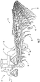
- FIGS. 1 and 2 illustrate differing perspective views of one embodiment of an agricultural implement 10 in accordance with aspects of the present subject matter.
- FIG. 1 illustrates a perspective view of the agricultural implement 10 coupled to a work vehicle 12.
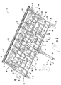
- FIG. 2 illustrates a perspective view of the implement 10, particularly illustrating various components of the implement 10.
- the implement 10 may be configured to be towed across a field along a direction of travel 14 by the work vehicle 12.
- the work vehicle 12 may be configured as an agricultural tractor having a plurality of track assemblies 16 for use in traversing the field. It should be appreciated, however, that the work vehicle 12 may be configured as any suitable work vehicle, such as a wheeled vehicle.
- the implement 10 may be coupled to the work vehicle 12 via a hitch assembly 18 or using any other suitable attachment means.
- the hitch assembly 18 may couple to an implement frame 20.
- the implement 10 may include the implement frame 20. As shown, the frame 20 may extend longitudinally between a forward end 22 and an aft end 24. The frame 20 may also extend laterally between a first side 26 and a second side 28.
- the frame 16 generally includes a plurality of structural frame members 30, such as beams, bars, and/or the like, configured to support or couple to a plurality of components. Additionally, a plurality of wheels may be coupled to the frame 20, such as a set of centrally located wheels 32 and a set of front pivoting wheels 34, to facilitate towing the implement 10 in the direction of travel 14.
- the frame 20 may be configured to support a cultivator 36, which may be configured to till or otherwise break the soil over which the implement 10 travels to create a seedbed.
- the cultivator 36 may include a plurality of ground engaging tools 38, which are pulled through the soil as the implement 10 moves across the field in the direction of travel 14.
- the ground engaging tools 38 may be configured to be pivotally mounted to the frame 20 to allow the ground engaging tools 38 pivot out of the way of rocks or other impediments in the soil.
- the ground engaging tools 38 may be arranged into a plurality of ranks 40, which are spaced apart from one another longitudinally between the forward end 22 and the aft end 24 of the frame 20.
- the frame 20 may include one or more sections. As illustrated in FIG. 2 , for example, the frame 20 may include a main section 42 positioned centrally between the first and second sides 26, 28 of the frame 20. The frame 20 may also include a first wing section 44 positioned proximate to the first side 26 of the frame 20. Similarly, the frame 20 may also include a second wing section 46 positioned proximate to the second side 28 of the frame 20. The first and second wing sections 44, 46 may be pivotally coupled to the main section 42 of the frame 20. In this respect, the first and second wing sections 44, 46 may be configured to fold up relative to the main section 42 to reduce the lateral width of the implement 10 to permit, for example, storage or transportation of the implement on a road. In should be appreciated that the frame 20 may include any suitable number of wing sections.
- the implement 10 may also include one or more harrows 48.
- the harrows 48 may be configured to be pivotally coupled to the frame 20.
- the harrows 48 may include a plurality of ground engaging elements 50, such as tines or spikes, which are configured to level or otherwise flatten any windrows or ridges in the soil created by the cultivator 36.
- the ground engaging elements 50 may be configured to be pulled through the soil as the implement 10 moves across the field in the direction of travel 14.
- the implement 10 may include any suitable number of harrows 48. In fact, some embodiments of the implement 10 may not include any harrows 48.
- the implement 10 may optionally include one or more baskets or rotary firming wheels 52.
- the baskets 52 may be configured to reduce the number of clods in the soil and/or firm the soil over which the implement 10 travels.
- each basket 52 may be configured to be pivotally coupled to one of the harrows 48.
- the baskets 52 may be configured to be pivotally coupled to the frame 20 or any other suitable location of the implement 10. It should be appreciated that the implement 10 may include any suitable number of baskets 52. In fact, some embodiments of the implement 10 may not include any baskets 52.
- FIG. 3 a side view of one embodiment of a system 100 for detecting ground engaging tool float for an agricultural implement is illustrated in accordance with aspects of the present subject matter.
- the system 100 will be described herein with reference to the implement 10 and one of the ground engaging tools 38 described above with reference to FIGS. 1-2 .
- the disclosed system 100 may generally be utilized with ground engaging tools having any other suitable ground engaging tool configuration and/or implements having any other suitable implement configuration.
- the system 100 may include a ground engaging tool 38 pivotally coupled to the implement frame 20.
- the ground engaging tool 38 may generally include a shank portion 39 configured to be pivotally coupled to the frame 20 (e.g., at pivot point 41) and a ground-engaging portion 43 extending from the shank portion 39 along a curved or arcuate profile.
- the ground-engaging portion 43 may include a tip end 45 that is configured to penetrate into or otherwise engage the ground as the implement 10 is being pulled through the field.
- the ground engaging tool 38 may be configured as a chisel.
- the ground engaging tool 38 may be configured as a sweep, tine, or any other suitable ground engaging tool.
- the system 100 may also include a biasing element 102 coupled between the frame 20 and the ground engaging tool 38.
- the biasing element 102 may be configured to bias the ground engaging tool 38 to a predetermined ground engaging tool position (e.g., a home or base position) relative to the frame 20.
- the predetermined ground engaging tool position may correspond to a ground engaging tool position in which the ground engaging tool 38 penetrates the soil to a desired depth.
- the predetermined ground engaging tool position may be set by a mechanical stop 104.
- the biasing element 102 may permit relative movement between the ground engaging tool 36 and the frame 20.
- the biasing element 102 may be configured to bias the ground engaging tool 38 to pivot relative to the frame 20 in a first pivot direction (e.g., as indicated by arrow 103 in FIG. 3 ) until an end 64 of the shank portion 39 of the ground engaging tool 38 contacts the stop 104.
- the biasing element 102 may also allow the ground engaging tool 38 to pivot away from the predetermined ground engaging tool position (e.g., to a shallower depth of penetration), such as in a second pivot direction (e.g., as indicated by arrow 101 in FIG. 3 ) opposite the first pivot direction 101, when encountering rocks or other impediments in the field.
- the biasing element 102 may be configured as a spring.
- the biasing element 102 may be configured as an actuator or any other suitable biasing element.
- the system 100 may also include a sensor 106 provided in operative association with the ground engaging tool 38 or the biasing element 102.
- the sensor 106 may be configured to detect an operating parameter indicative of a current position of the ground engaging tool 38 relative to the frame 20.
- the sensor 106 may generally correspond to any suitable sensor(s) or sensing device(s) that is configured to directly or indirectly detect the pivotal motion of the ground engaging tool 38.
- the sensor 106 may be configured as a rotary sensor 108 (e.g., a rotary potentiometer or a magnetic rotary sensor) coupled to one of the frame 20 or the ground engaging tool 38 and an associated sensor linkage 110 coupled between the rotary sensor 108 and the other adjacent component.
- a rotary sensor 108 e.g., a rotary potentiometer or a magnetic rotary sensor
- the rotary sensor 108 is coupled to a portion of the frame 20, with the sensor linkage 110 being coupled between the rotary sensor 108 and the ground engaging tool 38.
- the motion of the ground engaging tool 38 may be detected by the rotary sensor 108 via the mechanical linkage provided by the sensor linkage 110.
- the senor 106 may correspond to any other suitable sensor(s) or sensing device(s) configured to detect the pivotal motion of the ground engaging tool 38.
- the sensor 106 may correspond to a linear potentiometer, a proximity sensor, and/or any other suitable transducer (e.g., ultrasonic, electromagnetic, infrared, etc.) that allows the pivotal motion of the ground engaging tool 38 relative to the frame 20 to be directly or indirectly detected.
- FIG. 3 simply illustrates a single ground engaging tool 38 of the implement 10, with the biasing element 102 being coupled between the frame 20 and the illustrated ground engaging tool 38 and the sensor 106 being provided to monitor the displacement or pivotal motion of such ground engaging tool 38.
- a person of ordinary skill in the art will appreciate that any or all of the remaining ground engaging tools 38 of the disclosed implement 10 may similarly be provide in operative association with a corresponding biasing element 102 and an associated sensor 106.
- a biasing element 102 may be coupled to each of a plurality of ground engaging tools of the implement 10, such as ground engaging tools 54, 56, 58, 60, 62.
- a corresponding sensor 106 may be provided in operative association with each ground engaging tool 54, 56, 58, 60, 62 and/or its associated biasing element 102.
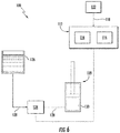
- the system 100 may further include a controller 112 configured to electronically control the operation of one or more components of the implement 10 or the work vehicle 12.
- the controller 112 may comprise any suitable processor-based device known in the art, such as a computing device or any suitable combination of computing devices.
- the controller 112 may include one or more processor(s) 114 and associated memory device(s) 116 configured to perform a variety of computer-implemented functions.
- processor refers not only to integrated circuits referred to in the art as being included in a computer, but also refers to a controller, a microcontroller, a microcomputer, a programmable logic controller (PLC), an application specific integrated circuit, and other programmable circuits.
- PLC programmable logic controller
- the memory device(s) 116 of the controller 112 may generally comprise memory element(s) including, but not limited to, a computer readable medium (e.g., random access memory (RAM)), a computer readable non-volatile medium (e.g., a flash memory), a floppy disk, a compact disc-read only memory (CD-ROM), a magneto-optical disk (MOD), a digital versatile disc (DVD) and/or other suitable memory elements.
- RAM random access memory
- a computer readable non-volatile medium e.g., a flash memory
- CD-ROM compact disc-read only memory
- MOD magneto-optical disk
- DVD digital versatile disc
- Such memory device(s) 116 may generally be configured to store suitable computer-readable instructions that, when implemented by the processor(s) 114, configure the controller 112 to perform various computer-implemented functions, such as one or more aspects of the methods 200 and 400 described below with reference to FIGS. 7 and 9 .
- the controller 112
- controller 112 may correspond to an existing controller of the implement 10 or the work vehicle 12 or the controller 112 may correspond to a separate processing device.
- the controller 112 may form all or part of a separate plug-in module that may be installed within the implement 10 or the work vehicle 12 to allow for the disclosed system and method to be implemented without requiring additional software to be uploaded onto existing control devices of the implement 10 or the work vehicle 12.
- the controller 112 may be configured to monitor a current position of the ground engaging tool 38 relative to the frame 20.
- the controller 112 may be communicatively coupled to the sensor 106, such as the rotary sensor 108, via a wired or wireless connection to allow measurement signals (e.g., indicated by dashed line 118 in FIG. 3 ) to be transmitted from the sensor 106 to the controller 112.
- the controller 112 may then be configured determine or estimate the current position of the ground engaging tool 38 relative to the frame 20 based on the measurement signals 118 received from the sensor 106.
- the controller 112 may include a look-up table or suitable mathematical formula stored within its memory 116 that correlates the sensor measurements to the current position of the ground engaging tool 38.
- the controller 112 may also be configured to determine when a ground engaging tool float event is occurring during operation of the implement 10. For instance, the controller 112 may be configured to determine when the ground engaging tool 38 is displaced from the predetermined ground engaging tool position by comparing the current position of the ground engaging tool 38 to the predetermined ground engaging tool position. Thereafter, in the event that the ground engaging tool 38 is displaced from the predetermined ground engaging tool position, the controller 112 may be configured identify a time period across which the ground engaging tool 38 is displaced from the predetermined ground engaging tool position.
- the controller 112 may compare the identified time period that the ground engaging tool 38 is displaced from the predetermined ground engaging tool position to a threshold time period associated with the occurrence of ground engaging tool float events. When the identified time period exceeds the threshold time period, the controller 112 may be configured to determine that a ground engaging tool float event has occurred.
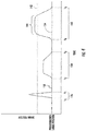
- FIG. 4 illustrates a graphical view of an example dataset charting the displacement of one of the ground engaging tools 38 of the implement 10 (e.g., as indicated by solid line 132) relative the predetermined ground engaging tool position (e.g., as indicated by dashed line 134) over time as monitored by the controller 112.
- the ground engaging tool 38 is displaced from its predetermined ground engaging tool position 134, such as at a first time period 136 between time t 0 and time t 1 , a second time period 138 between time t 2 and time t 3 , and a third time period 140 between time t 4 and t 5 .
- the controller 112 may be configured to identify the length of each time period and compare it to a given threshold time period. In the event that the length of any of such time periods exceeds the threshold time period, the controller 112 may determine that a float event has occurred. For instance, in the example dataset of FIG. 4 , it may be assumed that the first time period 136 is less than the threshold time period while the second and third time periods 138, 140 exceed the threshold time period. In such instance, the ground engaging tool displacement occurring across the first time period 136 may be indicative of a short, non-float displacement event, such as a ground engaging tool trip event occurring when the ground engaging tool 38 contacts a rock with the field and quickly pivots away from and back to the predetermined ground engaging tool position 132.
- a short, non-float displacement event such as a ground engaging tool trip event occurring when the ground engaging tool 38 contacts a rock with the field and quickly pivots away from and back to the predetermined ground engaging tool position 132.
- ground engaging tool displacement occurring across second and third time periods 138, 140 may be indicative of more prolonged displacement event, such as when the ground engaging tool floats away from the predetermined ground engaging tool position 132 for an extended period of time due to compacted or hardened soil conditions.
- the time period threshold utilized by the controller 112 may generally be selected so as to prevent instantaneous or significantly short displacement events from being classified as float events (e.g., ground engaging tool trip events occurring due to random contact with rocks or other impediments within the soil).
- the time period threshold may be greater than about 0.1 seconds, such as greater than about 0.5 seconds or greater than about 1 second or greater than about 2 seconds.
- the controller 112 may also be configured to identify when a ground engaging tool float event has occurred based at least partially on a magnitude of the displacement of the ground engaging tool 38 during operation of the implement 10. More specifically, the controller 112 may be configured to monitor the magnitude of the displacement of the ground engaging tool 38 relative to the predetermined ground engaging tool position. For instance, the controller 112 may be configured to determine the magnitude of the displacement of the ground engaging tool 38 relative to the predetermined ground engaging tool position by comparing the current position of the ground engaging tool 38 to the predetermined ground engaging tool position. Once the displacement of the ground engaging tool 38 is determined, the controller 112 may be configured to compare the determined displacement to a threshold displacement value (e.g., as indicated by line 142 in FIG.
- a threshold displacement value e.g., as indicated by line 142 in FIG.
- the controller 112 may be configured to identify the time period across which the displacement of the ground engaging tool 38 exceeds the threshold displacement value and compare the identified time period to the threshold time period. When the identified time period exceeds the threshold time period, the controller 112 may be configured to determine that the ground engaging tool float event has occurred.
- the controller 112 may only classify a portion of the third time period 140 as a float event. Specifically, even though the second time period 138 may correspond to a time period that exceeds the time period threshold, the magnitude of the ground engaging tool displacement never exceeds the threshold displacement value 142. In contrast, during the third time period 140, the ground engaging tool displacement exceeds the threshold displacement value 142 for a given period of time 144. Assuming such time period 144 exceeds the time period threshold, the controller 112 may identify such ground engaging tool displacement as corresponding to a float event.
- the controller 112 may be configured to initiate a control action associated with reducing the displacement defined between the current position of the ground engaging tool 38 and the predetermined ground engaging tool position. For instance, in one embodiment, the controller 112 may be configured to transmit a notification to the operator of the implement 10 (e.g., by causing a visual or audible notification or indicator to be presented to the operator within the work vehicle 12) that provides an indication that ground engaging tool float is occurring. In such instances, the operator may then choose to initiate any suitable corrective action he/she believes is necessary, such as by reducing the ground speed of the implement 10 and/or the work vehicle 12.
- the controller 112 may be configured to automatically control the operation of one or more components of the implement 10 and/or the work vehicle 12 (e.g., the vehicle's engine or transmission) in a manner that reduces the ground speed of the implement 10 and/or the work vehicle 12 when ground engaging tool float occurs, such as by reducing or limiting the engine power output.
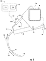
- the controller 112 may be configured to initiate any other suitable control action. For instance, as will be described below with reference to FIG. 6 , the controller 112 may be configured to automatically adjust the down pressure exerted on the ground engaging tool 38 by the biasing element 102 so as to reduce the displacement defined between the current position of the ground engaging tool 38 and the predetermined ground engaging tool position.
- the system 100 may generally be configured the same as or similar to that described above with reference to FIG. 3 .
- the system 100 may include a biasing element 102 coupled between the frame 20 and the ground engaging tool 38, with the biasing element 102 being configured to bias the ground engaging tool 38 to a predetermined ground engaging tool position relative to the frame 20.
- the biasing element 102 may be configured as a fluid-driven actuator 120, such as hydraulic actuator and/or a pneumatic actuator.
- the actuator 120 may be configured to adjust a down pressure exerted on the ground engaging tool 38 based on a fluid pressure associated with the fluid-driven actuator.
- the biasing element 102 may be a solenoid, a linear actuator, or any other suitable type of actuator.
- the system 100 may include a sensor 106 configured to monitor an operating parameter indicative of a current position of the ground engaging tool 38 relative to the frame 20.
- the sensor 106 may be configured as a pressure sensor 122 provided in operative association with the fluid-driven actuator 120.
- the pressure sensor 122 may be configured to detect or measure a pressure of a fluid supplied within the actuator 120.
- the pressure sensor 122 may be provided in fluid communication with a fluid chamber defined within the actuator 120 (e.g., a piston-side chamber or a rod-side chamber of the actuator 120).
- the pressure sensor 122 may be installed at any other suitable location that allows the pressure sensor 122 to measure the pressure of the fluid supplied within the actuator 120, such as by installing the pressure sensor 122 in fluid communication with a hose or conduit configured to supply fluid to the actuator 120.
- the pressure of the fluid supplied within the actuator 120 may, in turn, be indicative of the current position of the ground engaging tool 38 relative to the frame 20.
- the controller 112 may include a look-up table or suitable mathematical formula stored within its memory 116 that correlates the pressure measurements to the current position of the ground engaging tool 38.
- the actuator 120 corresponds to a hydraulic cylinder.
- the actuator 120 also correspond to any other suitable fluid-driven actuator, such as a pneumatic actuator.
- the controller 112 may, in several embodiments, be configured to be coupled to suitable components for automatically controlling the operation of the actuator 120, thereby allowing the controller 112 to actively adjust the adjust the down pressure exerted on the ground engaging tool 38.
- the controller 112 may be communicatively coupled to a suitable pressure regulating valve 124 (PRV) (e.g., a solenoid-activated valve) configured to regulate the pressure of hydraulic fluid supplied to the actuator 120 (e.g., from a hydraulic fluid tank 126 or pump of the implement 10 or the work vehicle 12 via one or more fluid conduits 128).
- PRV pressure regulating valve 124
- the controller 112 may be coupled to the PRV 124 so as to regulate the pressure of the hydraulic fluid supplied to a cap or piston end 130 of the actuator 120 (e.g., via one or more conduits 128).
- the pressure of the fluid supplied from the PRV 124 may be directly proportional to the pressure supplied at the piston end 130 of the actuator 120, thereby allowing the controller 112 to control the displacement of the actuator 120.
- FIG. 6 only illustrates the controller 112 coupled to a single PRV for controlling the operation of the actuator 120 for one of the ground engaging tools 38, similar hydraulic components may be utilized to control the corresponding actuators 120 associated with the remaining ground engaging tools 38 of the implement 10.
- the controller 112 may be configured to automatically control the operation of the actuator 120 so as to increase the down pressure on the ground engaging tool 38.
- the controller 112 may be configured to detect the occurrence of ground engaging tool float with respect to the displacement of the ground engaging tool 38.
- the controller 112 may be configured to electronically control operation of the PRV 124 to adjust the fluid pressure supplied within the actuator 120.
- the controller 112 may be configured to control the operation of the PRV 124 such that the fluid pressure supplied to the actuator 120 is increased when it is detected that a ground engaging tool float is occurring.
- Increasing the fluid pressure within the actuator 120 may increase the down pressure on the ground engaging tool 38, which, in turn, may reduce the displacement defined between the current position of the ground engaging tool 38 and the predetermined ground engaging tool position.
- the sensor 106 is described above as being configured as a rotary sensor 108 ( FIG. 3 ) or a pressure sensor 120 ( FIG. 5 ), a person of ordinary skill in the art would appreciate that the sensor 108 may be any suitable sensor(s) or sensing device(s) configured to detect an operating parameter indicative of the current position of the ground engaging tool 38 relative to the frame 20.
- the sensor 106 may be configured as an accelerometer coupled to the ground engaging tool 38. As such, when the ground engaging tool 38 pivots relative to the frame 20, the acceleration of the ground engaging tool 38 relative to the frame 20 may be detected by the accelerometer. The acceleration of the ground engaging tool 38 may, in turn, be indicative of the current position of the ground engaging tool 38 relative to the frame 20.
- the controller 112 may be configured to determine the current position of the ground engaging tool 38 based on a duration of the detected acceleration.
- the controller 112 may include a look-up table or suitable mathematical formula stored within its memory 116 that correlates the acceleration measurements to the current position of the ground engaging tool 38.
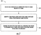
- FIG. 7 a flow diagram of one embodiment of a method 200 for detecting ground engaging tool float for an agricultural implement is illustrated in accordance with aspects of the present subject matter.
- the method 200 will be described herein with reference to the implement 10, the ground engaging tools 38, and the system 100 described above with reference to FIGS. 1-6 .
- the disclosed method 200 may generally be utilized to detect ground engaging tool float for any agricultural implement having any suitable implement configuration and/or of any ground engaging tool having any suitable ground engaging tool configuration.
- FIG. 7 depicts steps performed in a particular order for purposes of illustration and discussion, the methods discussed herein are not limited to any particular order or arrangement.
- steps of the methods disclosed herein can be omitted, rearranged, combined, and/or adapted in various ways without deviating from the scope of the present disclosure.
- the method 200 may include receiving data indicative of a current position of a ground engaging tool relative to a frame of an agricultural implement.
- the controller 112 may be communicatively coupled to a sensor 106 configured to monitor an operating parameter indicative of the current position of the ground engaging tool 38 relative to the frame 20.
- measurement signals or sensor data 118 transmitted from the sensor 106 may be received by the controller 112 for monitoring the current position and/or displacement of the ground engaging tool 38.
- the method 200 may include identifying a time period across which the ground engaging tool is displaced from a predetermined ground engaging tool position. Specifically, as indicated above, the controller 112 may monitor the current position of the ground engaging tool 38 relative to the predetermined ground engaging tool position so as to determine when the ground engaging tool 38 is displaced from the predetermined ground engaging tool position. The controller 112 may then identify the time period across which the ground engaging tool 38 is displaced from the predetermined ground engaging tool position.
- the method 200 may include comparing the identified time period to a threshold time period to determine when a ground engaging tool float event is occurring during operation of the implement. For instance, as described above with reference to FIG. 4 , the controller 112 may compare the identified time period to a corresponding threshold time period. Thereafter, assuming that the identified time period exceeds the threshold time period, the controller 112 may determine that a ground engaging tool float event has occurred across such identified time period.
- the method 200 may also include initiating a control action associated with reducing the displacement defined between the current position of the ground engaging tool and the predetermined ground engaging tool position when it is determined that a ground engaging tool float event is occurring.
- control actions may include controlling one or more components of the implement 10 and/or the work vehicle 12.
- the controller 112 may, in one embodiment, be configured to control one or more operator-interface components located within the vehicle's cab to allow a visual and/or audible notification to be presented to the operator.
- the controller 112 may be configured to automatically initiate a control action that results in the ground speed of the implement 10 and/or the work vehicle 12 being reduced, such as by automatically controlling the operation of the vehicle's engine and/or transmission.
- the controller 112 may also be configured to actively regulate the pressure of the fluid supplied within an associated actuator 120 (e.g., by electronically controlling the associated PRV 124) to adjust the down pressure on the ground engaging tool 38.
- the disclosed system 100 may be utilized to monitor the displacement of two or more of the ground engaging tools of an implement.
- the implement 10 may include a plurality of ground engaging tools 38 spaced apart from one another laterally between the first and second sides 26, 28 of the frame 20.
- each ground engaging tool 38 may experience differing magnitudes of displacement due to variations in soil conditions across the lateral width of the frame 20.
- the soil compacted by tracks or wheels of the work vehicle 12 towing the implement 10 may be much firmer than other areas of the field.
- the controller 112 may be configured to determine or calculate an instantaneous or current global ground engaging tool displacement parameter for the implement 10 based on the monitored ground engaging tool displacements. Thereafter, the controller 112 may be configured to identify a soil condition for a swath of the field currently being traversed by the implement 10 based on a comparison between the determined current global ground engaging tool displacement parameter and an associated global displacement threshold.
- one of the ground engaging tools 38 of the implement 10 may correspond a first ground engaging tool 54 configured to be pivotally coupled to the main section 42 of the frame 20, such as at a central location of the main frame 42.
- the implement 10 may also include second and third ground engaging tools 56, 58 configured to be respectively pivotally coupled to the first and second wing sections 44, 46 of the frame 20, such as at central locations thereof.
- the implement 10 may include fourth and fifth ground engaging tools 60, 62 configured to be pivotally coupled to the main section 42 of the frame 20 and laterally aligned with the tracks 16 of the work vehicle 12 (e.g., with tracks 16 being indicated by dashed boxes in FIG. 2 ).
- the fourth and fifth ground engaging tools 60, 62 may, instead, be laterally aligned with the wheels of the work vehicle 12.
- the various ground engaging tools 54, 56, 58, 60, 62 may, in one embodiment, be configured to be pivotally coupled to the forward end 22 of the frame 20, such as within a longitudinally forward-most rank of the plurality of ranks 40.
- FIG. 8 a schematic view of one embodiment of a system 300 for monitoring soil conditions within a field is illustrated in accordance with aspects of the present subject matter.
- the system 300 will be described herein with reference to the implement 10 and the ground engaging tools 54, 56, 58, 60, 62 described above with reference to FIGS. 1-2 .
- the disclosed system 300 may generally be utilized with ground engaging tools having any other suitable ground engaging tool configuration and/or implements having any other suitable implement configuration.
- the system 300 may include a plurality of the sensors 106 communicatively coupled to an associated controller 112, with each sensor 106 being provided in operative association with one of the ground engaging tools 54, 56, 58, 60, 62 (or with its corresponding biasing element 102) to allow the sensors 106 to detect an operating parameter indicative of the current position of each ground engaging tool 54, 56, 58, 60, 62 relative to the implement's frame 20.
- each sensor 106 may correspond to a rotary sensor 108, a pressure sensor 120, or any other suitable sensor(s) or sensing device(s) that is configured to directly or indirectly detect the pivotal motion of its associated ground engaging tool 54, 56, 58, 60, 62.
- the controller 112 may be configured to monitor the displacement of each ground engaging tool 54, 56, 58, 60, 62 relative to its predetermined ground engaging tool position.
- the controller 112 may include a look-up table or suitable mathematical formula stored within its memory 116 that correlates the sensor measurements to the displacements of the various ground engaging tools 54, 56, 58, 60, 62.
- the controller 112 may also be configured to determine a current global ground engaging tool displacement parameter for the implement 10 based on the monitored displacements of the ground engaging tools 54, 56, 58, 60, 62. For example, in one embodiment, the controller 112 may be configured to compare the individual monitored displacements of the various ground engaging tools 54, 56, 58, 60, 62 to determine an instantaneous or current maximum displacement value for the ground engaging tools 54, 56, 58, 60, 62 as the implement 10 is being traversed over a portion of the field. In such an embodiment, the controller 112 may be configured to identify such instantaneous or current maximum displacement value as the current global ground engaging tool displacement parameter for the implement 10.
- the controller 112 may be configured to calculate an instantaneous or current average displacement value for the individual monitored displacements of the ground engaging tools 54, 56, 58, 60, 62 as the implement 10 is being traversed over a given portion of the field. In such an embodiment, the controller 112 may be configured to identify such average displacement value as the current global ground engaging tool displacement parameter for the implement 10.
- the controller 112 may also be configured to identify a soil condition for the portion of the field currently being traversed by the implement 10 based on a comparison between the current global ground engaging tool displacement parameter and a predetermined global displacement threshold associated with the implement 10. For instance, the controller 112 may be configured to compare the current global ground engaging tool displacement parameter determined for the implement 10 to the associated global displacement threshold.
- the controller 112 may be configured to indicate that the portion of the field currently being traversed by the implement 10 has a first soil condition, such as a compacted or firm soil condition. Conversely, when the current global ground engaging tool displacement parameter falls below the predetermined global displacement threshold, the controller 112 may be configured to indicate that the portion of the field currently being traversed by the implement 10 has a second soil condition, such as a loose or uncompacted soil condition. Additionally, in one embodiment, the controller 112 may be configured to generate a field map that visually identifies the soil conditions for the field across each portion of the field traversed by the implement 10.
- the controller 112 determines the current global ground engaging tool displacement parameter and identifies the corresponding soil condition continuously as the implement 10 traverses the field. For example, the controller 112 may determine the current global ground engaging tool displacement parameter and the corresponding soil condition once a predetermined time interval has elapsed (e.g., every 0.1 second, or every 0.5 second, or every 1 second, etc.). In this respect, controller 112 is able to identify location-specific changes in the soil condition as the implement is traversed across the field.
- a predetermined time interval e.g., every 0.1 second, or every 0.5 second, or every 1 second, etc.
- the controller 112 may be configured to initiate a global control action associated with reducing the displacement of the ground engaging tools 54, 56, 58, 60, 62. For instance, in one embodiment, the controller 112 may be configured to transmit a notification to the operator of the implement 10 (e.g., by causing a visual or audible notification or indicator to be presented to the operator within the work vehicle 12) that provides an indication that the current global ground engaging tool displacement parameter has exceeded the predetermined global displacement threshold. In such instances, the operator may then choose to initiate any suitable corrective action he/she believes is necessary, such as by reducing the ground speed of the implement 10 and/or the work vehicle 12.
- a notification e.g., by causing a visual or audible notification or indicator to be presented to the operator within the work vehicle 12
- the operator may then choose to initiate any suitable corrective action he/she believes is necessary, such as by reducing the ground speed of the implement 10 and/or the work vehicle 12.
- the controller 112 may be configured to automatically control the operation of one or more components of the implement and/or the work vehicle 12 (e.g., the vehicle's engine or transmission) in a manner that reduces the ground speed of the implement 10 and/or the work vehicle 12 when the current global ground engaging tool displacement parameter exceeds the predetermined global displacement threshold, such as by reducing or limiting the engine power output.
- the controller 112 may be configured to initiate any other suitable control action. For instance, as described above with reference to FIG.
- the controller 112 may be configured to automatically adjust the down pressure exerted on the ground engaging tools 54, 56, 58, 60, 62 so as to reduce the displacement defined between the current position of the ground engaging tools 54, 56, 58, 60, 62 and the predetermined ground engaging tool position.
- the controller 112 may also be configured to determine a global soil condition for the field.
- the global soil condition may provide an indication of the overall quality of the field, such as that the soil condition for the field is "good” or "bad.”
- the controller 112 may be configured to determine a percentage of the field traversed by the implement 10 across which the current global ground engaging tool displacement parameter exceeded the predetermined global displacement threshold. The controller 112 may then compare the identified percentage of the field to an associated threshold value to determine the global soil condition for the field.
- the controller 112 may be configured to determine the number of times that the current global ground engaging tool displacement parameter exceeded the predetermined global displacement threshold as the implement 10 was being pulled across the field. Thereafter, the controller 112 may compare the identified number of times to an associated threshold value to determine the global level soil condition for the field. For instance, if the identified number exceeds the associated threshold value, the overall soil condition for the field may be classified as "bad”; whereas, if the identified number is less than the associated threshold value, the overall soil condition for the field may be classified as "good.”
- the controller 112 may also be configured to determine when a ground engaging tool float event is occurring based on the global ground engaging tool displacement parameter (as opposed to making such a determination based on the individual displacement of a given ground engaging tool). For instance, the controller 112 may be configured to identify a time period across which the current global ground engaging tool displacement parameter exceeds the predetermined global displacement threshold. The controller 112 may then compare the identified time period to an associated threshold time period. Thereafter, assuming that the identified time period exceeds the threshold time period, the controller 112 may determine that a ground engaging tool float event is occurring during operation of the implement 10.
- FIG. 9 a flow diagram of one embodiment of a method 400 for monitoring soil conditions within a field is illustrated in accordance with aspects of the present subject matter.
- the method 400 will be described herein with reference to the implement 10, the ground engaging tools 38, 54, 56, 58, 60, 62, and the system 300 described above with reference to FIGS. 1-8 .
- the disclosed method 400 may generally be utilized to monitor soil conditions using any agricultural implement having any suitable implement configuration and/or any ground engaging tool having any suitable ground engaging tool configuration.
- FIG. 9 depicts steps performed in a particular order for purposes of illustration and discussion, the methods discussed herein are not limited to any particular order or arrangement.
- steps of the methods disclosed herein can be omitted, rearranged, combined, and/or adapted in various ways without deviating from the scope of the present disclosure.
- the method 400 may include receiving data indicative of a current position of each of a plurality of ground engaging tools relative to a predetermined ground engaging tool position.
- the controller 112 may be communicatively coupled to a plurality of sensors 106, with each sensor being configured to monitor an operating parameter indicative of the current position of a corresponding ground engaging tool 54, 56, 58, 60, 62.
- the measurement signals 118 transmitted from each sensor 106 may be received by the controller 112 for monitoring the current position and/or displacement of each associated ground engaging tool.
- the method 400 may include determining a current global ground engaging tool displacement parameter for the implement based on the monitored displacements of the ground engaging tools. For instance, as indicated above, the controller 112 may, in one embodiment, be configured to determine the current global ground engaging tool displacement parameter for the implement 10 by identifying the instantaneous or current maximum displacement value of the various monitored ground engaging tool displacements. In another embodiment, the controller 112 may be configured to determine the current global ground engaging tool displacement parameter for the implement 10 by calculating an instantaneous or average displacement value for the various monitored ground engaging tool displacements.
- the method 400 may include identifying a soil condition for a portion of the field currently being traversed by the implement based on a comparison between the current global ground engaging tool displacement parameter and a predetermined global displacement threshold set for the implement. For instance, as indicated above, if the current global ground engaging tool displacement parameter exceeds the predetermined global displacement threshold, the controller 112 may identify that the portion of the field currently being traversed by the implement 10 has a first soil condition, such as a compacted or hardened soil condition. Alternatively, if the current global ground engaging tool displacement parameter is less than predetermined global displacement threshold, the controller 112 may identify that the portion of the field currently being traversed by the implement 10 has a second soil condition, such as a soft or loosened soil condition. Moreover, in several embodiments, the controller 112 may also generate a field map that visually identifies the soil conditions for the field across each portion of the field traversed by the implement 10.
- the method 400 may also include determining a global soil condition for the field. For instance, the controller 112 determine a percentage of the field traversed by the implement across which the current global ground engaging tool displacement parameter exceeded the predetermined global displacement threshold and compare the identified percentage to an associated threshold value to determine a global soil condition for the field. In another embodiment, the controller 112 may determine a number of times that the current global ground engaging tool displacement parameter exceeded the predetermined global displacement threshold and compare the identified number of times to an associated threshold value to determine a global soil condition for the field.
- the method 400 may also include initiating a control action associated with reducing the displacement of the ground engaging tools when the global ground engaging tool displacement parameter exceeds the predetermined displacement threshold.
- the controller 112 may initiate a control action associated with reducing the displacement of the ground engaging tools 54, 56, 58, 60, 62 when the global ground engaging tool displacement parameter exceeds the predetermined displacement threshold.
Landscapes
- Life Sciences & Earth Sciences (AREA)
- Engineering & Computer Science (AREA)
- Mechanical Engineering (AREA)
- Soil Sciences (AREA)
- Environmental Sciences (AREA)
- Physics & Mathematics (AREA)
- General Physics & Mathematics (AREA)
- Zoology (AREA)
- Soil Working Implements (AREA)
Claims (11)
- Anordnung (100) zum Erkennen des Aufschwimmens eines in den Boden eingreifenden Werkzeugs eines landwirtschaftlichen Arbeitsgeräts (10), wobei die Anordnung (100) umfasst:ein Arbeitsgerät (10) mit einem Rahmen (20) und einem in den Boden eingreifenden Werkzeug (38), das schwenkbar mit dem Rahmen (20) verbunden ist;ein Vorspannelement (102), das zwischen dem Rahmen (20) und dem in den Boden eingreifenden Werkzeug (38) angebracht ist, wobei das Vorspannelement (102) dazu eingerichtet ist, das in den Boden eingreifende Werkzeug (38) in eine vorbestimmte Position des in den Boden eingreifenden Werkzeugs relativ zum Rahmen (20) vorzuspannen, wobei die vorbestimmte Position des in den Boden eingreifenden Werkzeugs einer Position entspricht, in der das in den Boden eingreifende Werkzeug (38) bis zu einer gewünschten Tiefe in den Boden eindringt;einen Sensor (106), der in Wirkverbindung mit dem in den Boden eingreifenden Werkzeug (38) oder dem Vorspannelement (102) vorgesehen ist, wobei der Sensor (106) dazu eingerichtet ist, einen Parameter zu erkennen, der kennzeichnend für eine aktuelle Position des in den Boden eingreifenden Werkzeugs (38) relativ zum Rahmen (20) ist;eine Steuereinrichtung (112), die kommunizierend mit dem Sensor (106) verbunden ist, wobei die Steuereinrichtung (112) dazu eingerichtet ist, die aktuelle Position des in den Boden eingreifenden Werkzeugs (38) basierend auf von dem Sensor (106) empfangenen Messsignalen (118) zu überwachen,wobei die Steuereinrichtung (112) dazu eingerichtet ist:eine Zeitspanne zu bestimmen, während der die überwachte aktuelle Position besagt, dass das in den Boden eingreifende Werkzeug (38) aus der vorbestimmten Position des in den Boden eingreifenden Werkzeugs derart verschoben ist, dass die Tiefe des Eindringens in den Boden unter den gewünschten Wert abgenommen hat; unddie bestimmte Zeitspanne mit einem Zeitspannengrenzwert zu vergleichen, der dem Auftreten von Aufschwimmereignissen des in den Boden eingreifenden Werkzeugs zugeordnet ist, um zu bestimmen, dass während des Betriebs des Arbeitsgeräts (10) ein Aufschwimmereignis des in den Boden eingreifenden Werkzeugs auftritt, wenn die bestimmte Zeitspanne den Zeitspannengrenzwert überschreitet.
- Anordnung (100) nach Anspruch 1, wobei die Steuereinrichtung (112) weiterhin dazu eingerichtet ist, eine Größe der Verschiebung des in den Boden eingreifenden Werkzeugs (38) relativ zur vorbestimmten Position des in den Boden eingreifenden Werkzeugs mit einem Verschiebungsgrenzwert zu vergleichen, wobei die Steuereinrichtung (112) dazu eingerichtet ist, die Zeitspanne zu bestimmen, während der die Verschiebung des in den Boden eingreifenden Werkzeugs (38) den Verschiebungsgrenzwert überschreitet, und die bestimmte Zeitspanne mit dem Zeitspannengrenzwert zu vergleichen.
- Anordnung (110) nach einem der vorangehenden Ansprüche, wobei die Steuereinrichtung (112) dazu eingerichtet ist, eine Steuerungsmaßnahme zu ergreifen, die damit verbunden ist, die Verschiebung zu reduzieren, die zwischen der aktuellen Position des in den Boden eingreifenden Werkzeugs (38) und der vorbestimmten Position des in den Boden eingreifenden Werkzeugs definiert ist, wenn bestimmt wird, dass ein Aufschwimmereignis des in den Boden eingreifenden Werkzeugs auftritt, wobei die Steuerungsmaßnahme mit zumindest einem der folgenden verknüpft ist:Einstellen eines nach unten gerichteten Drucks, der vom Vorspannelement (102) auf das in den Boden eingreifende Werkzeug (38) ausgeübt wird;Verringern einer Fahrgeschwindigkeit des Arbeitsgeräts (10); undBenachrichtigen eines Bedieners des Arbeitsgeräts (10) über das Auftreten des Aufschwimmereignisses des in den Boden eingreifenden Werkzeugs.
- Anordnung (100) nach einem der vorangehenden Ansprüche, wobei das Vorspannelement (102) einem fluidbetriebenem Antrieb (120) entspricht, der dazu eingerichtet ist, einen nach unten gerichteten Druck, der auf das in den Boden eingreifende Werkzeug (38) ausgeübt wird, basierend auf einem Fluiddruck einzustellen, der dem fluidbetriebenen Antrieb (120) zugeordnet ist.
- Anordnung (100) nach Anspruch 4, wobei der Sensor (106) einen Drucksensor (122) umfasst, der dazu eingerichtet ist, den Fluiddruck zu erkennen, der dem fluidbetriebenen Antrieb (120) zugeordnet ist, wobei der Fluiddruck kennzeichnend für die aktuelle Position des in den Boden eingreifenden Werkzeugs (38) relativ zum Rahmen (20) ist.
- Anordnung (100) nach einem der vorangehenden Ansprüche, wobei die vorbestimmte Position des in den Boden eingreifenden Werkzeugs (38) durch einen mechanischen Anschlag (104) festgelegt ist.
- Anordnung (100) nach einem der vorangehenden Ansprüche, wobei der Sensor (106) einen Rotationssensor (108), der mit dem Rahmen (20) oder dem in den Boden eingreifenden Werkzeug (38) verbunden ist, und ein Sensorverbindungselement (110) umfasst, das zwischen dem Rotationssensor (108) und dem anderen aus Rahmen (20) und in den Boden eingreifenden Werkzeug (38) verbunden ist, wobei der Rotationssensor (108) dazu eingerichtet ist, einen Winkel zwischen dem Rahmen (20) und dem in den Boden eingreifenden Werkzeug (38) zu erfassen, wobei der Winkel kennzeichnend für die aktuelle Position des in den Boden eingreifenden Werkzeugs (38) relativ zum Rahmen (20) ist.
- Anordnung (100) nach einem der vorangehenden Ansprüche, wobei das Vorspannelement (102) eine Feder umfasst.
- Verfahren (200) zum Erkennen eines Aufschwimmereignisses eines in den Boden eingreifenden Werkzeugs während des Betriebs eines landwirtschaftlichen Arbeitsgeräts (10), wobei das Arbeitsgerät (10) einen Rahmen (20) und ein in den Boden eingreifendes Werkzeug (38) umfasst, das schwenkbar mit dem Rahmen (20) verbunden ist, wobei das Arbeitsgerät (10) weiterhin ein Vorspannelement (102) umfasst, das zwischen dem Rahmen (20) und dem in den Boden eingreifenden Werkzeug (38) angebracht ist, wobei das Vorspannelement (102) dazu eingerichtet ist, das in den Boden eingreifende Werkzeug (38) in eine vorbestimmte Position des in den Boden eingreifenden Werkzeugs relativ zum Rahmen (20) vorzuspannen, wobei die vorbestimmte Position des in den Boden eingreifenden Werkzeugs einer Position entspricht, in der das in den Boden eingreifende Werkzeug (38) bis zu einer gewünschten Tiefe in den Boden eindringt, wobei das Verfahren (200) umfasst:Empfangen von Daten mittels einer Rechenvorrichtung, die kennzeichnend für eine aktuelle Position des in den Boden eingreifenden Werkzeugs (38) relativ zum Rahmen (20) sind;Überwachen der aktuellen Position des in den Boden eingreifenden Werkzeugs (38) basierend auf den empfangenen Daten mittels der Rechenvorrichtung;Bestimmen einer Zeitspanne, während der die überwachte aktuelle Position besagt, dass das in den Boden eingreifende Werkzeug (38) aus der vorbestimmten Position des in den Boden eingreifenden Werkzeugs derart verschoben ist, dass die Tiefe des Eindringens in den Boden unter die gewünschte Tiefe abgenommen hat, mittels der Rechenvorrichtung; undVergleichen der bestimmten Zeitspanne mit einem Zeitspannengrenzwert mittels der Rechenvorrichtung, der dem Auftreten von Aufschwimmereignissen des in den Boden eingreifenden Werkzeugs zugeordnet ist, um zu bestimmen, dass ein Aufschwimmereignis des in den Boden eingreifenden Werkzeugs während des Betriebs des Arbeitsgeräts (10) auftritt, wenn die bestimmte Zeitspanne den Zeitspannengrenzwert überschreitet.
- Verfahren (200) nach Anspruch 9, weiterhin umfassend:Vergleichen einer Größe der Verschiebung des in den Boden eingreifenden Werkzeugs (38) relativ zur vorbestimmten Position des in den Boden eingreifenden Werkzeugs mit einem Verschiebungsgrenzwert mittels der Rechenvorrichtung;Bestimmen einer Zeitspanne, während der die Verschiebung des in den Boden eingreifenden Werkzeugs (38) den Verschiebungsgrenzwert überschreitet, mittels der Rechenvorrichtung; undVergleichen der bestimmten Zeitspanne mit dem Zeitspannengrenzwert mittels der Rechenvorrichtung.
- Verfahren (200) nach einem der Ansprüche 9 oder 10, weiterhin umfassend:
Ergreifen einer Steuerungsmaßnahme, die mit der Reduzierung der Verschiebung verbunden ist, die zwischen der aktuellen Position des in den Boden eingreifenden Werkzeugs (38) und der vorbestimmten Position des in den Boden eingreifenden Werkzeugs definiert ist, mittels der Rechenvorrichtung, wenn bestimmt wird, dass das Aufschwimmereignis des in den Boden eingreifenden Werkzeugs auftritt, wobei das Ergreifen der Steuerungsmaßnahme zumindest eines der folgenden umfasst:Einstellen eines nach unten gerichteten Drucks, der vom Vorspannelement (102) auf das in den Boden eingreifende Werkzeug (38) ausgeübt wird;Verringern der Fahrgeschwindigkeit des Arbeitsgeräts (10); undBenachrichtigen eines Bedieners des Arbeitsgeräts (10) über das Auftreten des Aufschwimmereignisses des in den Boden eingreifenden Werkzeugs.
Applications Claiming Priority (1)
| Application Number | Priority Date | Filing Date | Title |
|---|---|---|---|
| US15/581,704 US11259454B2 (en) | 2017-04-28 | 2017-04-28 | System and method for detecting ground engaging tool float for an agricultural implement |
Publications (2)
| Publication Number | Publication Date |
|---|---|
| EP3400764A1 EP3400764A1 (de) | 2018-11-14 |
| EP3400764B1 true EP3400764B1 (de) | 2020-03-18 |
Family
ID=62025726
Family Applications (1)
| Application Number | Title | Priority Date | Filing Date |
|---|---|---|---|
| EP18168014.1A Active EP3400764B1 (de) | 2017-04-28 | 2018-04-18 | System und verfahren zur erkennung des aufschwimmens eines bodeneingriffswerkzeugs für ein landwirtschaftliches arbeitsgerät |
Country Status (2)
| Country | Link |
|---|---|
| US (1) | US11259454B2 (de) |
| EP (1) | EP3400764B1 (de) |
Families Citing this family (24)
| Publication number | Priority date | Publication date | Assignee | Title |
|---|---|---|---|---|
| DK3656195T3 (da) * | 2018-11-26 | 2023-04-03 | Cmn Maskintec As | Fremgangsmåde til mekanisk ukrudtsbekæmpelse af en afgrødemark og en fjedertandsharve til en sådan fremgangsmåde |
| EP3729934A1 (de) | 2019-04-25 | 2020-10-28 | CNH Industrial Sweden AB | Pflug |
| EP3965544B1 (de) | 2019-05-10 | 2024-11-27 | Great Plains Manufacturing, Inc. | Steuerungssystem für landwirtschaftliche arbeitsgeräte und verfahren |
| AT521778B1 (de) * | 2019-05-16 | 2020-07-15 | Thomas Hatzenbichler Agro Technik Gmbh | Bodenbearbeitungsgerät |
| US11202403B2 (en) * | 2019-05-31 | 2021-12-21 | Cnh Industrial America Llc | System and method for detecting the operational status of a residue removal device of a seed-planting implement |
| US11206753B2 (en) * | 2019-06-14 | 2021-12-28 | Cnh Industrial America Llc | System and method for controlling an agricultural implement during the performance of a tillage operation |
| DE102019116518A1 (de) * | 2019-06-18 | 2020-12-24 | Horsch Maschinen Gmbh | Vorspanneinrichtung und Vorrichtung zur landwirtschaftlichen Bodenbearbeitung |
| US11944028B2 (en) | 2019-08-14 | 2024-04-02 | Cnh Industrial America Llc | Systems and methods for monitoring the installation status of a shank attachment member of an agricultural implement |
| US11219153B2 (en) * | 2019-08-29 | 2022-01-11 | Cnh Industrial America Llc | System and method for monitoring shank float |
| US11530528B2 (en) * | 2019-10-29 | 2022-12-20 | Cnh Industrial America Llc | System and method for detecting tripping of ground engaging tools based on implement frame motion |
| US12114587B2 (en) * | 2019-10-31 | 2024-10-15 | Deere & Company | Work machine control systems to monitor ground engagement tools and map obstacles |
| US11805721B2 (en) | 2019-10-31 | 2023-11-07 | Deere & Company | Work machine control systems to monitor ground engagement tools and map obstacles |
| US11445654B2 (en) * | 2020-01-16 | 2022-09-20 | Cnh Industrial Canada, Ltd. | System and method for identifying plugging of ground engaging tools based on lifting pressure |
| US11617294B2 (en) | 2020-03-26 | 2023-04-04 | Cnh Industrial America Llc | Orientation control system for an agricultural implement |
| US11558993B2 (en) | 2020-03-26 | 2023-01-24 | Cnh Industrial America Llc | Soil monitoring system for an agricultural tillage implement |
| US11602092B2 (en) | 2020-03-26 | 2023-03-14 | Cnh Industrial America Llc | Frame control system for an agricultural implement |
| US11638393B2 (en) * | 2020-03-26 | 2023-05-02 | Cnh Industrial America Llc | Ground engaging tool monitoring system |
| US12022756B2 (en) | 2020-03-26 | 2024-07-02 | Cnh Industrial America Llc | Orientation control system for an agricultural implement |
| US11730076B2 (en) | 2020-03-26 | 2023-08-22 | Cnh Industrial America Llc | Control system for an agricultural implement |
| CN117083434A (zh) * | 2021-03-25 | 2023-11-17 | 住友重机械工业株式会社 | 挖土机及施工管理系统 |
| US12022757B2 (en) * | 2021-03-29 | 2024-07-02 | Cnh Industrial America Llc | Systems and methods for detecting changes in the operating condition of a frame assembly of an agricultural implement based on load imbalances |
| FR3138597A1 (fr) * | 2022-08-08 | 2024-02-09 | Jean EGRETIER | Dispositif de sécurité pour outil agricole travaillant en déport par rapport à un véhicule, système agricole et procédé correspondant |
| US20240172575A1 (en) * | 2022-11-29 | 2024-05-30 | Cnh Industrial America Llc | System and method for detecting tripping and/or floating events of ground-engaging shanks on an agricultural implement |
| US12276088B2 (en) | 2023-03-09 | 2025-04-15 | Cnh Industrial Canada, Ltd. | Agricultural system and method for detecting failure of a ground-engaging tool of an agricultural implement |
Family Cites Families (37)
| Publication number | Priority date | Publication date | Assignee | Title |
|---|---|---|---|---|
| US2565668A (en) | 1947-04-08 | 1951-08-28 | Minneapolis Moline Co | Spring trip standard for cultivators |
| US4031963A (en) | 1975-04-14 | 1977-06-28 | Erhard Poggemiller | Depth control device for ground working agricultural implements |
| US4044838A (en) | 1975-04-21 | 1977-08-30 | American Tractor Equipment Corporation | Automatic control for ripper tool |
| US4293043A (en) | 1979-09-12 | 1981-10-06 | Haybuster Manufacturing, Inc. | Soil undercutter with trip release for pivotally mounted shank |
| US4567689A (en) | 1983-12-30 | 1986-02-04 | Lemons Daniel P | Vineyard cultivator |
| US4723608A (en) | 1986-09-30 | 1988-02-09 | Deere & Company | Depth sensing skid assembly |
| US4930581A (en) | 1988-05-10 | 1990-06-05 | Fleischer Manufacturing, Inc. | Guidance control apparatus for agricultural implement |
| JP2580351B2 (ja) | 1989-12-28 | 1997-02-12 | 株式会社小松製作所 | 衝撃リッパの自動制御装置 |
| US5390745A (en) | 1992-05-07 | 1995-02-21 | Brown Manufacturing Corporation | Cultivator with sweep and sifting assemblies |
| US5450908A (en) * | 1993-04-14 | 1995-09-19 | Krause Plow Corporation, Inc. | Spring-cushioned hydraulic depth control system for tillage implements |
| US5579850A (en) | 1994-10-12 | 1996-12-03 | Sugano Farm Machinery Mfg. Co., Ltd. | Cultivating system and cultivating machine with plow-depth control function |
| US6041582A (en) | 1998-02-20 | 2000-03-28 | Case Corporation | System for recording soil conditions |
| US6112145A (en) | 1999-01-26 | 2000-08-29 | Spectra Precision, Inc. | Method and apparatus for controlling the spatial orientation of the blade on an earthmoving machine |
| US8083004B2 (en) | 2007-03-29 | 2011-12-27 | Caterpillar Inc. | Ripper autodig system implementing machine acceleration control |
| BRPI0817450B1 (pt) | 2007-09-26 | 2018-12-18 | Prec Planting Inc | método de determinar quando ajustar a força descendente suplementar |
| US8090507B2 (en) | 2008-01-23 | 2012-01-03 | Gradient Inc. | Pitch plow and method of controlling an elevation of a cutting edge of a pitch plow |
| US9285501B2 (en) | 2008-11-04 | 2016-03-15 | Veris Technologies, Inc. | Multiple sensor system and method for mapping soil in three dimensions |
| US8473166B2 (en) | 2009-05-19 | 2013-06-25 | Topcon Positioning Systems, Inc. | Semiautomatic control of earthmoving machine based on attitude measurement |
| US8688331B2 (en) | 2009-12-18 | 2014-04-01 | Agco Corporation | Method to enhance performance of sensor-based implement height control |
| US8346442B2 (en) * | 2010-03-22 | 2013-01-01 | Cnh Canada, Ltd. | System and method for determining ground engaging tool position based on fluid pressure |
| US9232687B2 (en) | 2010-09-15 | 2016-01-12 | Dawn Equipment Company | Agricultural systems |
| US8985232B2 (en) | 2012-08-20 | 2015-03-24 | Dawn Equipment Company | Agricultural apparatus for sensing and providing feedback of soil property changes in real time |
| DE102010062861A1 (de) | 2010-12-10 | 2012-06-14 | Andreas Heiß | Landwirtschaftliche Maschine |
| RU2562211C2 (ru) | 2011-04-27 | 2015-09-10 | Кинз Мэньюфэкчеринг, Инк. | Дистанционное регулирование рядного блока устройства сельскохозяйственного назначения |
| US8201388B1 (en) | 2011-05-02 | 2012-06-19 | Deere & Company | Sensor for a header height control system |
| US9511633B2 (en) | 2011-08-17 | 2016-12-06 | Deere & Company | Soil compaction management and reporting |
| US9433142B2 (en) | 2011-11-08 | 2016-09-06 | Buhler Ezee-On Inc. | Tool control system for agricultural seeders |
| US9271440B2 (en) | 2011-11-08 | 2016-03-01 | Buhler Ezec-On Inc. | Parallel linkage opener with adjustable spring loaded packer wheel |
| US8827001B2 (en) | 2012-01-17 | 2014-09-09 | Cnh Industrial America Llc | Soil monitoring system |
| EP2679085A1 (de) | 2012-06-26 | 2014-01-01 | Norac Systems International Inc. | Höhenkontrolle |
| GB2510629B (en) | 2013-02-11 | 2015-10-14 | Kverneland Group Les Landes Genusson | Strip tilling system |
| US9629304B2 (en) | 2013-04-08 | 2017-04-25 | Ag Leader Technology | On-the go soil sensors and control methods for agricultural machines |
| WO2015164811A1 (en) | 2014-04-25 | 2015-10-29 | Cnh Industrial America Llc | System and method for controlling an agricultural system based on soil analysis |
| US9282688B2 (en) * | 2014-04-25 | 2016-03-15 | Deere & Company | Residue monitoring and residue-based control |
| US20160029547A1 (en) | 2014-07-30 | 2016-02-04 | Deere & Company | Sensing the soil profile behind a soil-engaging implement |
| DE102015000984A1 (de) | 2015-01-27 | 2016-07-28 | Alois Pöttinger Maschinenfabrik Ges.m.b.H. | Bodenbearbeitungsgerät |
| CA2952513A1 (en) * | 2016-01-13 | 2017-07-13 | Precision Ag 360, Inc. | Agricultural ground penetrating tool sensor system |
-
2017
- 2017-04-28 US US15/581,704 patent/US11259454B2/en active Active
-
2018
- 2018-04-18 EP EP18168014.1A patent/EP3400764B1/de active Active
Non-Patent Citations (1)
| Title |
|---|
| None * |
Also Published As
| Publication number | Publication date |
|---|---|
| US20180310466A1 (en) | 2018-11-01 |
| US11259454B2 (en) | 2022-03-01 |
| EP3400764A1 (de) | 2018-11-14 |
Similar Documents
| Publication | Publication Date | Title |
|---|---|---|
| EP3400764B1 (de) | System und verfahren zur erkennung des aufschwimmens eines bodeneingriffswerkzeugs für ein landwirtschaftliches arbeitsgerät | |
| EP3403478B1 (de) | System und verfahren zur überwachung von bodenverhältnissen innerhalb eines feldes | |
| US11297757B2 (en) | System for monitoring the displacement of a ground engaging tool | |
| US10838432B2 (en) | System and method for monitoring frame levelness of an agricultural implement | |
| US11558990B2 (en) | System and method for detecting a plug of a tool of a tillage implement | |
| US10750656B2 (en) | System and method for monitoring the frame levelness of an agricultural implement | |
| EP3815482B1 (de) | Vorrichtung und verfahren zur detektion der ebenheit von werkzeugen eines bodenbearbeitungsgeräts auf basis der werkzeugbelastung | |
| US20210029865A1 (en) | System for determining material accumulation relative to ground engaging tools of an agricultural implement and related methods | |
| US20190320574A1 (en) | System for creating soil compaction maps and associated methods for controlling the operation of a tillage implement | |
| US20230345852A1 (en) | System and method for detecting levelness of tools of a tillage implement based on material flow | |
| EP4033873B1 (de) | System und verfahren zur einstellung des abstandes zwischen bodenbearbeitungswerkzeugen eines landwirtschaftlichen arbeitsgeräts | |
| US11369052B2 (en) | System and method for monitoring plugging of basket assemblies of an agricultural implement | |
| US10542658B2 (en) | System for adjusting down pressure loads on ground engaging elements of an agricultural implement | |
| EP4066610B1 (de) | Systeme und verfahren zur erkennung von materialansammlungen in zusammenhang mit scheibensatzanordnungen von landwirtschaftlichen arbeitsgeräten | |
| US12082517B2 (en) | System and method for detecting material accumulation relative to rotating ground-engaging tools of an agricultural implement | |
| US20200084952A1 (en) | System and method for determining soil roughness of a field across which an agricultural implement is being moved based on ground engaging tool acceleration | |
| US12004442B2 (en) | System and method for detecting material accumulation relative to rotating ground-penetrating tools of an agricultural implement |
Legal Events
| Date | Code | Title | Description |
|---|---|---|---|
| PUAI | Public reference made under article 153(3) epc to a published international application that has entered the european phase |
Free format text: ORIGINAL CODE: 0009012 |
|
| STAA | Information on the status of an ep patent application or granted ep patent |
Free format text: STATUS: THE APPLICATION HAS BEEN PUBLISHED |
|
| AK | Designated contracting states |
Kind code of ref document: A1 Designated state(s): AL AT BE BG CH CY CZ DE DK EE ES FI FR GB GR HR HU IE IS IT LI LT LU LV MC MK MT NL NO PL PT RO RS SE SI SK SM TR |
|
| AX | Request for extension of the european patent |
Extension state: BA ME |
|
| STAA | Information on the status of an ep patent application or granted ep patent |
Free format text: STATUS: REQUEST FOR EXAMINATION WAS MADE |
|
| 17P | Request for examination filed |
Effective date: 20190514 |
|
| RBV | Designated contracting states (corrected) |
Designated state(s): AL AT BE BG CH CY CZ DE DK EE ES FI FR GB GR HR HU IE IS IT LI LT LU LV MC MK MT NL NO PL PT RO RS SE SI SK SM TR |
|
| GRAP | Despatch of communication of intention to grant a patent |
Free format text: ORIGINAL CODE: EPIDOSNIGR1 |
|
| STAA | Information on the status of an ep patent application or granted ep patent |
Free format text: STATUS: GRANT OF PATENT IS INTENDED |
|
| INTG | Intention to grant announced |
Effective date: 20190704 |
|
| GRAS | Grant fee paid |
Free format text: ORIGINAL CODE: EPIDOSNIGR3 |
|
| GRAA | (expected) grant |
Free format text: ORIGINAL CODE: 0009210 |
|
| STAA | Information on the status of an ep patent application or granted ep patent |
Free format text: STATUS: THE PATENT HAS BEEN GRANTED |
|
| AK | Designated contracting states |
Kind code of ref document: B1 Designated state(s): AL AT BE BG CH CY CZ DE DK EE ES FI FR GB GR HR HU IE IS IT LI LT LU LV MC MK MT NL NO PL PT RO RS SE SI SK SM TR |
|
| REG | Reference to a national code |
Ref country code: GB Ref legal event code: FG4D |
|
| REG | Reference to a national code |
Ref country code: DE Ref legal event code: R096 Ref document number: 602018003060 Country of ref document: DE |
|
| REG | Reference to a national code |
Ref country code: AT Ref legal event code: REF Ref document number: 1244819 Country of ref document: AT Kind code of ref document: T Effective date: 20200415 Ref country code: IE Ref legal event code: FG4D |
|
| PG25 | Lapsed in a contracting state [announced via postgrant information from national office to epo] |
Ref country code: FI Free format text: LAPSE BECAUSE OF FAILURE TO SUBMIT A TRANSLATION OF THE DESCRIPTION OR TO PAY THE FEE WITHIN THE PRESCRIBED TIME-LIMIT Effective date: 20200318 Ref country code: NO Free format text: LAPSE BECAUSE OF FAILURE TO SUBMIT A TRANSLATION OF THE DESCRIPTION OR TO PAY THE FEE WITHIN THE PRESCRIBED TIME-LIMIT Effective date: 20200618 Ref country code: RS Free format text: LAPSE BECAUSE OF FAILURE TO SUBMIT A TRANSLATION OF THE DESCRIPTION OR TO PAY THE FEE WITHIN THE PRESCRIBED TIME-LIMIT Effective date: 20200318 |
|
| REG | Reference to a national code |
Ref country code: NL Ref legal event code: MP Effective date: 20200318 |
|
| PG25 | Lapsed in a contracting state [announced via postgrant information from national office to epo] |
Ref country code: BG Free format text: LAPSE BECAUSE OF FAILURE TO SUBMIT A TRANSLATION OF THE DESCRIPTION OR TO PAY THE FEE WITHIN THE PRESCRIBED TIME-LIMIT Effective date: 20200618 Ref country code: HR Free format text: LAPSE BECAUSE OF FAILURE TO SUBMIT A TRANSLATION OF THE DESCRIPTION OR TO PAY THE FEE WITHIN THE PRESCRIBED TIME-LIMIT Effective date: 20200318 Ref country code: SE Free format text: LAPSE BECAUSE OF FAILURE TO SUBMIT A TRANSLATION OF THE DESCRIPTION OR TO PAY THE FEE WITHIN THE PRESCRIBED TIME-LIMIT Effective date: 20200318 Ref country code: LV Free format text: LAPSE BECAUSE OF FAILURE TO SUBMIT A TRANSLATION OF THE DESCRIPTION OR TO PAY THE FEE WITHIN THE PRESCRIBED TIME-LIMIT Effective date: 20200318 Ref country code: GR Free format text: LAPSE BECAUSE OF FAILURE TO SUBMIT A TRANSLATION OF THE DESCRIPTION OR TO PAY THE FEE WITHIN THE PRESCRIBED TIME-LIMIT Effective date: 20200619 |
|
| REG | Reference to a national code |
Ref country code: LT Ref legal event code: MG4D |
|
| PG25 | Lapsed in a contracting state [announced via postgrant information from national office to epo] |
Ref country code: NL Free format text: LAPSE BECAUSE OF FAILURE TO SUBMIT A TRANSLATION OF THE DESCRIPTION OR TO PAY THE FEE WITHIN THE PRESCRIBED TIME-LIMIT Effective date: 20200318 |
|
| PG25 | Lapsed in a contracting state [announced via postgrant information from national office to epo] |
Ref country code: LT Free format text: LAPSE BECAUSE OF FAILURE TO SUBMIT A TRANSLATION OF THE DESCRIPTION OR TO PAY THE FEE WITHIN THE PRESCRIBED TIME-LIMIT Effective date: 20200318 Ref country code: CZ Free format text: LAPSE BECAUSE OF FAILURE TO SUBMIT A TRANSLATION OF THE DESCRIPTION OR TO PAY THE FEE WITHIN THE PRESCRIBED TIME-LIMIT Effective date: 20200318 Ref country code: RO Free format text: LAPSE BECAUSE OF FAILURE TO SUBMIT A TRANSLATION OF THE DESCRIPTION OR TO PAY THE FEE WITHIN THE PRESCRIBED TIME-LIMIT Effective date: 20200318 Ref country code: SK Free format text: LAPSE BECAUSE OF FAILURE TO SUBMIT A TRANSLATION OF THE DESCRIPTION OR TO PAY THE FEE WITHIN THE PRESCRIBED TIME-LIMIT Effective date: 20200318 Ref country code: IS Free format text: LAPSE BECAUSE OF FAILURE TO SUBMIT A TRANSLATION OF THE DESCRIPTION OR TO PAY THE FEE WITHIN THE PRESCRIBED TIME-LIMIT Effective date: 20200718 Ref country code: PT Free format text: LAPSE BECAUSE OF FAILURE TO SUBMIT A TRANSLATION OF THE DESCRIPTION OR TO PAY THE FEE WITHIN THE PRESCRIBED TIME-LIMIT Effective date: 20200812 Ref country code: EE Free format text: LAPSE BECAUSE OF FAILURE TO SUBMIT A TRANSLATION OF THE DESCRIPTION OR TO PAY THE FEE WITHIN THE PRESCRIBED TIME-LIMIT Effective date: 20200318 Ref country code: SM Free format text: LAPSE BECAUSE OF FAILURE TO SUBMIT A TRANSLATION OF THE DESCRIPTION OR TO PAY THE FEE WITHIN THE PRESCRIBED TIME-LIMIT Effective date: 20200318 |
|
| REG | Reference to a national code |
Ref country code: AT Ref legal event code: MK05 Ref document number: 1244819 Country of ref document: AT Kind code of ref document: T Effective date: 20200318 |
|
| REG | Reference to a national code |
Ref country code: DE Ref legal event code: R097 Ref document number: 602018003060 Country of ref document: DE |
|
| PG25 | Lapsed in a contracting state [announced via postgrant information from national office to epo] |
Ref country code: MC Free format text: LAPSE BECAUSE OF FAILURE TO SUBMIT A TRANSLATION OF THE DESCRIPTION OR TO PAY THE FEE WITHIN THE PRESCRIBED TIME-LIMIT Effective date: 20200318 |
|
| PLBE | No opposition filed within time limit |
Free format text: ORIGINAL CODE: 0009261 |
|
| STAA | Information on the status of an ep patent application or granted ep patent |
Free format text: STATUS: NO OPPOSITION FILED WITHIN TIME LIMIT |
|
| PG25 | Lapsed in a contracting state [announced via postgrant information from national office to epo] |
Ref country code: LU Free format text: LAPSE BECAUSE OF NON-PAYMENT OF DUE FEES Effective date: 20200418 Ref country code: ES Free format text: LAPSE BECAUSE OF FAILURE TO SUBMIT A TRANSLATION OF THE DESCRIPTION OR TO PAY THE FEE WITHIN THE PRESCRIBED TIME-LIMIT Effective date: 20200318 Ref country code: DK Free format text: LAPSE BECAUSE OF FAILURE TO SUBMIT A TRANSLATION OF THE DESCRIPTION OR TO PAY THE FEE WITHIN THE PRESCRIBED TIME-LIMIT Effective date: 20200318 Ref country code: AT Free format text: LAPSE BECAUSE OF FAILURE TO SUBMIT A TRANSLATION OF THE DESCRIPTION OR TO PAY THE FEE WITHIN THE PRESCRIBED TIME-LIMIT Effective date: 20200318 |
|
| REG | Reference to a national code |
Ref country code: BE Ref legal event code: MM Effective date: 20200430 |
|
| 26N | No opposition filed |
Effective date: 20201221 |
|
| PG25 | Lapsed in a contracting state [announced via postgrant information from national office to epo] |
Ref country code: BE Free format text: LAPSE BECAUSE OF NON-PAYMENT OF DUE FEES Effective date: 20200430 Ref country code: PL Free format text: LAPSE BECAUSE OF FAILURE TO SUBMIT A TRANSLATION OF THE DESCRIPTION OR TO PAY THE FEE WITHIN THE PRESCRIBED TIME-LIMIT Effective date: 20200318 |
|
| PG25 | Lapsed in a contracting state [announced via postgrant information from national office to epo] |
Ref country code: IE Free format text: LAPSE BECAUSE OF NON-PAYMENT OF DUE FEES Effective date: 20200418 |
|
| PG25 | Lapsed in a contracting state [announced via postgrant information from national office to epo] |
Ref country code: SI Free format text: LAPSE BECAUSE OF FAILURE TO SUBMIT A TRANSLATION OF THE DESCRIPTION OR TO PAY THE FEE WITHIN THE PRESCRIBED TIME-LIMIT Effective date: 20200318 |
|
| REG | Reference to a national code |
Ref country code: DE Ref legal event code: R082 Ref document number: 602018003060 Country of ref document: DE Representative=s name: KROHER STROBEL RECHTS- UND PATENTANWAELTE PART, DE |
|
| PG25 | Lapsed in a contracting state [announced via postgrant information from national office to epo] |
Ref country code: CH Free format text: LAPSE BECAUSE OF NON-PAYMENT OF DUE FEES Effective date: 20210430 Ref country code: LI Free format text: LAPSE BECAUSE OF NON-PAYMENT OF DUE FEES Effective date: 20210430 |
|
| PG25 | Lapsed in a contracting state [announced via postgrant information from national office to epo] |
Ref country code: TR Free format text: LAPSE BECAUSE OF FAILURE TO SUBMIT A TRANSLATION OF THE DESCRIPTION OR TO PAY THE FEE WITHIN THE PRESCRIBED TIME-LIMIT Effective date: 20200318 Ref country code: MT Free format text: LAPSE BECAUSE OF FAILURE TO SUBMIT A TRANSLATION OF THE DESCRIPTION OR TO PAY THE FEE WITHIN THE PRESCRIBED TIME-LIMIT Effective date: 20200318 Ref country code: CY Free format text: LAPSE BECAUSE OF FAILURE TO SUBMIT A TRANSLATION OF THE DESCRIPTION OR TO PAY THE FEE WITHIN THE PRESCRIBED TIME-LIMIT Effective date: 20200318 |
|
| PG25 | Lapsed in a contracting state [announced via postgrant information from national office to epo] |
Ref country code: MK Free format text: LAPSE BECAUSE OF FAILURE TO SUBMIT A TRANSLATION OF THE DESCRIPTION OR TO PAY THE FEE WITHIN THE PRESCRIBED TIME-LIMIT Effective date: 20200318 Ref country code: AL Free format text: LAPSE BECAUSE OF FAILURE TO SUBMIT A TRANSLATION OF THE DESCRIPTION OR TO PAY THE FEE WITHIN THE PRESCRIBED TIME-LIMIT Effective date: 20200318 |
|
| PGFP | Annual fee paid to national office [announced via postgrant information from national office to epo] |
Ref country code: DE Payment date: 20250428 Year of fee payment: 8 |
|
| PGFP | Annual fee paid to national office [announced via postgrant information from national office to epo] |
Ref country code: GB Payment date: 20250422 Year of fee payment: 8 |
|
| PGFP | Annual fee paid to national office [announced via postgrant information from national office to epo] |
Ref country code: IT Payment date: 20250422 Year of fee payment: 8 |
|
| PGFP | Annual fee paid to national office [announced via postgrant information from national office to epo] |
Ref country code: FR Payment date: 20250424 Year of fee payment: 8 |