US11528836B2 - System and method for sequentially controlling agricultural implement ground-engaging tools - Google Patents
System and method for sequentially controlling agricultural implement ground-engaging tools Download PDFInfo
- Publication number
- US11528836B2 US11528836B2 US16/692,229 US201916692229A US11528836B2 US 11528836 B2 US11528836 B2 US 11528836B2 US 201916692229 A US201916692229 A US 201916692229A US 11528836 B2 US11528836 B2 US 11528836B2
- Authority
- US
- United States
- Prior art keywords
- ground
- field
- engaging tool
- value
- operating parameter
- Prior art date
- Legal status (The legal status is an assumption and is not a legal conclusion. Google has not performed a legal analysis and makes no representation as to the accuracy of the status listed.)
- Active, expires
Links
Images


Classifications
-
- A—HUMAN NECESSITIES
- A01—AGRICULTURE; FORESTRY; ANIMAL HUSBANDRY; HUNTING; TRAPPING; FISHING
- A01B—SOIL WORKING IN AGRICULTURE OR FORESTRY; PARTS, DETAILS, OR ACCESSORIES OF AGRICULTURAL MACHINES OR IMPLEMENTS, IN GENERAL
- A01B79/00—Methods for working soil
- A01B79/005—Precision agriculture
-
- A—HUMAN NECESSITIES
- A01—AGRICULTURE; FORESTRY; ANIMAL HUSBANDRY; HUNTING; TRAPPING; FISHING
- A01B—SOIL WORKING IN AGRICULTURE OR FORESTRY; PARTS, DETAILS, OR ACCESSORIES OF AGRICULTURAL MACHINES OR IMPLEMENTS, IN GENERAL
- A01B63/00—Lifting or adjusting devices or arrangements for agricultural machines or implements
- A01B63/002—Devices for adjusting or regulating the position of tools or wheels
-
- A—HUMAN NECESSITIES
- A01—AGRICULTURE; FORESTRY; ANIMAL HUSBANDRY; HUNTING; TRAPPING; FISHING
- A01B—SOIL WORKING IN AGRICULTURE OR FORESTRY; PARTS, DETAILS, OR ACCESSORIES OF AGRICULTURAL MACHINES OR IMPLEMENTS, IN GENERAL
- A01B63/00—Lifting or adjusting devices or arrangements for agricultural machines or implements
- A01B63/02—Lifting or adjusting devices or arrangements for agricultural machines or implements for implements mounted on tractors
- A01B63/10—Lifting or adjusting devices or arrangements for agricultural machines or implements for implements mounted on tractors operated by hydraulic or pneumatic means
- A01B63/111—Lifting or adjusting devices or arrangements for agricultural machines or implements for implements mounted on tractors operated by hydraulic or pneumatic means regulating working depth of implements
- A01B63/1112—Lifting or adjusting devices or arrangements for agricultural machines or implements for implements mounted on tractors operated by hydraulic or pneumatic means regulating working depth of implements using a non-tactile ground distance measurement, e.g. using reflection of waves
-
- A—HUMAN NECESSITIES
- A01—AGRICULTURE; FORESTRY; ANIMAL HUSBANDRY; HUNTING; TRAPPING; FISHING
- A01B—SOIL WORKING IN AGRICULTURE OR FORESTRY; PARTS, DETAILS, OR ACCESSORIES OF AGRICULTURAL MACHINES OR IMPLEMENTS, IN GENERAL
- A01B63/00—Lifting or adjusting devices or arrangements for agricultural machines or implements
- A01B63/14—Lifting or adjusting devices or arrangements for agricultural machines or implements for implements drawn by animals or tractors
- A01B63/24—Tools or tool-holders adjustable relatively to the frame
- A01B63/28—Tools or tool-holders adjustable relatively to the frame operated by the machine or implement
-
- A—HUMAN NECESSITIES
- A01—AGRICULTURE; FORESTRY; ANIMAL HUSBANDRY; HUNTING; TRAPPING; FISHING
- A01B—SOIL WORKING IN AGRICULTURE OR FORESTRY; PARTS, DETAILS, OR ACCESSORIES OF AGRICULTURAL MACHINES OR IMPLEMENTS, IN GENERAL
- A01B71/00—Construction or arrangement of setting or adjusting mechanisms, of implement or tool drive or of power take-off; Means for protecting parts against dust, or the like; Adapting machine elements to or for agricultural purposes
- A01B71/02—Setting or adjusting mechanisms
-
- A—HUMAN NECESSITIES
- A01—AGRICULTURE; FORESTRY; ANIMAL HUSBANDRY; HUNTING; TRAPPING; FISHING
- A01B—SOIL WORKING IN AGRICULTURE OR FORESTRY; PARTS, DETAILS, OR ACCESSORIES OF AGRICULTURAL MACHINES OR IMPLEMENTS, IN GENERAL
- A01B69/00—Steering of agricultural machines or implements; Guiding agricultural machines or implements on a desired track
- A01B69/001—Steering by means of optical assistance, e.g. television cameras
-
- A—HUMAN NECESSITIES
- A01—AGRICULTURE; FORESTRY; ANIMAL HUSBANDRY; HUNTING; TRAPPING; FISHING
- A01B—SOIL WORKING IN AGRICULTURE OR FORESTRY; PARTS, DETAILS, OR ACCESSORIES OF AGRICULTURAL MACHINES OR IMPLEMENTS, IN GENERAL
- A01B7/00—Disc-like soil-working implements usable either as ploughs or as harrows, or the like
Definitions
- the present disclosure generally relates to agricultural implements and, more particularly, to systems and methods for sequentially controlling a plurality of ground-engaging tools of an agricultural implement.
- a farmer To attain the best agricultural performance from a piece of land, a farmer must cultivate the soil, typically through one or more tillage operations. Common tillage operations include plowing, harrowing, and sub-soiling. Modern farmers perform these tillage operations by pulling a tillage implement behind an agricultural work vehicle, such as a tractor. Depending on the crop selection and the soil conditions, a farmer may need to perform several tillage operations at different times over a crop cycle to properly cultivate the land to suit the crop choice.
- the present subject matter is directed to a system for controlling ground-engaging tools of an agricultural implement.
- the system may include a first ground-engaging tool configured to perform a first operation on a field as the agricultural implement is moved across the field.
- the system may include a second ground-engaging tool configured to perform a second operation on the field as the agricultural implement is moved across the field.
- the system may include a sensor configured to capture data indicative of a field characteristic of the field.
- the system may include a controller communicatively coupled to the sensor. As such, the controller may be configured to determine a first value of the field characteristic based on the data captured by the sensor and adjust an operating parameter of the first ground-engaging tool based on the determined first value. After adjusting the operating parameter of the first ground-engaging tool, the controller may be configured to determine a second value of the field characteristic based on the data captured by the sensor and adjust an operating parameter of the second ground-engaging tool based on the determined second value.
- the present subject matter is directed to a method for controlling ground-engaging tools of an agricultural implement.
- the agricultural implement may include a first ground-engaging tool configured to perform a first operation on a field as the agricultural implement is moved across the field.
- the agricultural implement may include a second ground-engaging tool configured to perform a second operation on the field as the agricultural implement is moved across the field.
- the method may include determining, with one or more computing devices, a first value of a field characteristic of the field based on received sensor data. Additionally, the method may include adjusting, with the one or more computing devices, an operating parameter of the first ground-engaging tool based on the determined first value.
- the method may include determining, with the one or more computing devices, a second value of the field characteristic based on the received sensor data. Moreover, the method may include adjusting, with the one or more computing devices, an operating parameter of the second ground-engaging tool based on the determined second value.
- FIG. 1 illustrates a perspective view of one embodiment of a work vehicle towing an agricultural implement in accordance with aspects of the present subject matter
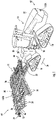
- FIG. 2 illustrates a perspective view of the agricultural implement shown in FIG. 1 ;
- FIG. 3 illustrates a schematic view of one embodiment of a system for controlling the ground-engaging tools of an agricultural implement in accordance with aspects of the present subject matter
- FIG. 4 illustrates a flow diagram of one embodiment of a method for controlling the ground-engaging tools of an agricultural implement in accordance with aspects of the present subject matter.
- the present subject matter is directed to systems and methods for controlling the ground-engaging tools of an agricultural implement.
- the implement may include one or more first ground-engaging tools configured to perform a first operation on a field as a work vehicle tows the implement travels across the field.
- the implement may include one or more second ground-engaging tools configured to perform a second operation on the field as the work vehicle tows the implement travels across the field.
- the first ground-engaging tool(s) may correspond to a leveling blade(s) configured to level the soil in the field and the second ground-engaging tool(s) may correspond to a shank(s) configured to incorporate the soil.
- a controller of the disclosed system may be configured to sequentially control the operation of the first and second ground-engaging tools. More specifically, the controller may be configured to determine a first value(s) of a field characteristic(s) (e.g., residue coverage, soil clod size, soil levelness, or compaction layer depth) of the field based on received sensor data. The controller may then be configured to adjust one or more operating parameters of the first ground-engaging tool(s) based on the determined first value(s) of the field characteristic(s). Such an adjustment(s) may impact the field characteristic(s) in a manner that requires further adjustment of the operation of the implement.
- a field characteristic(s) e.g., residue coverage, soil clod size, soil levelness, or compaction layer depth
- the controller may be configured to determine a second value(s) of the field characteristic(s) based on the received sensor data. Thereafter, the controller may be configured to adjust one or more operating parameters of the second ground-engaging tool(s) based on the determined second value(s) of the field characteristic(s).
- FIGS. 1 and 2 illustrate perspective views of one embodiment of a work vehicle 10 and an associated agricultural implement 12 in accordance with aspects of the present subject matter.
- FIG. 1 illustrates a perspective view of the vehicle 10 towing the implement 12 (e.g., across a field).
- FIG. 2 illustrates a perspective view of the implement 12 shown in FIG. 1 .
- the vehicle 10 is configured as an agricultural tractor and the implement 12 is configured as a tillage implement.
- the vehicle 10 may be configured as any other suitable agricultural vehicle.
- the implement 12 may be configured as any other suitable agricultural implement.
- the vehicle 10 includes a pair of front track assemblies 14 (one is shown), a pair of rear track assemblies 16 (one is shown), and a frame or chassis 18 coupled to and supported by the track assemblies 14 , 16 .
- An operator's cab 20 may be supported by a portion of the chassis 18 and may house various input devices for permitting an operator to control the operation of one or more components of the vehicle 10 and/or one or more components of the implement 12 .
- the vehicle 10 may include an engine 22 and a transmission 24 mounted on the chassis 18 .
- the transmission 24 may be operably coupled to the engine 22 and may provide variably adjusted gear ratios for transferring engine power to the track assemblies 14 , 16 via a drive axle assembly (not shown) (or via axles if multiple drive axles are employed).
- the implement 12 may generally include a carriage frame assembly 30 configured to be towed by the vehicle 10 via a pull hitch or tow bar 32 in a travel direction of the vehicle 10 (e.g., as indicated by arrow 34 ).
- the carriage frame assembly 30 may be configured to support a plurality of ground-engaging tools, such as a plurality of shanks, disk blades, leveling blades, tines, basket assemblies, and/or the like.
- the ground-engaging tools may be configured to perform various tillage operations (e.g., plowing, leveling, and/or the like) on the field along which the implement 12 is being towed.
- the carriage frame assembly 30 may include aft-extending carrier frame members 36 coupled to the tow bar 32 .
- reinforcing gusset plates 38 may be used to strengthen the connection between the tow bar 32 and the carrier frame members 36 .
- the carriage frame assembly 30 may generally support a central frame 40 , a forward frame 42 positioned forward of the central frame 40 in the direction of travel 34 , and an aft frame 44 positioned aft of the central frame 40 in the direction of travel 34 . As shown in FIG.
- the central frame 40 may correspond to a shank frame configured to support a plurality of ground-engaging shanks 46 configured to mix or incorporate the soil as the implement 12 is towed across the field.
- the central frame 40 may be configured to support any other suitable ground-engaging tools.
- the forward frame 42 may correspond to a disk frame configured to support various gangs or sets 48 of disk blades 50 .
- each disk blade 50 may, for example, include both a concave side (not shown) and a convex side (not shown).
- the various gangs 48 of disk blades 50 may be oriented at an angle relative to the travel direction 34 of the work vehicle 10 . As such, the disk blades 50 may chop up residue, weeds, and other plant matter and incorporate such plant matter into the soil.
- the forward frame 42 may be configured to support any other suitable ground-engaging tools.
- the aft frame 44 may also be configured to support a plurality of ground-engaging tools.
- the aft frame 44 is configured to support a plurality of leveling blades 52 and rolling (or crumbler) basket assemblies 54 positioned aft of the shanks 46 .
- the leveling blades 52 may be configured to level ridges formed in the soil by the shanks 46 .
- the basket assemblies 54 may be configured to break up soil clods present on the surface of the field.
- any other suitable ground-engaging tools may be coupled to and supported by the aft frame 44 , such as a plurality closing disks.
- the implement 12 may also include any number of suitable actuators (e.g., hydraulic cylinders) for adjusting the relative positioning of, penetration depth of, and/or force applied to the various ground-engaging tools 46 , 50 , 52 , 54 .
- the implement 12 may include one or more first actuators 56 coupled to the central frame 40 for raising or lowering the central frame 40 relative to the ground, thereby allowing adjustment of the penetration depth of and/or the forced applied to the shanks 46 .
- the implement 12 may include one or more second actuators 58 coupled to the disk forward frame 42 to adjust the penetration depth of and/or the force applied to the disk blades 50 .
- the implement 12 may include one or more third actuators 60 coupled to the aft frame 44 to allow the aft frame 44 to be moved relative to the central frame 40 , thereby allowing the relevant operating parameters of the ground-engaging tools 52 , 54 supported by the aft frame 44 (e.g., the force applied to and/or the penetration depth of) to be adjusted.
- the relevant operating parameters of the ground-engaging tools 52 , 54 supported by the aft frame 44 e.g., the force applied to and/or the penetration depth of
- the configuration of the work vehicle 10 described above and shown in FIG. 1 is provided only to place the present subject matter in an exemplary field of use.
- the present subject matter may be readily adaptable to any manner of work vehicle configuration.
- a separate frame or chassis may be provided to which the engine, transmission, and drive axle assembly are coupled, a configuration common in smaller tractors.
- Still other configurations may use an articulated chassis to steer the work vehicle 10 or rely on tires/wheels in lieu of the track assemblies 14 , 16 .
- each frame section of the implement 12 may be configured to support any suitable type of ground-engaging tools, such as by installing closing disks on the aft frame 44 of the implement 12 .
- the vehicle/implement 10 / 12 may include one or more field characteristic sensors coupled thereto and/or mounted thereon. As will be described below, each field characteristic sensor may be configured to capture data associated with a portion of the field across which the vehicle/implement 10 / 12 is traveling. The captured data may, in turn, be indicative of one or more field characteristic of the field, such as the residue coverage, soil clod size, soil levelness, and/or compaction layer location.
- the field characteristic sensor(s) may be provided in operative association with the vehicle/implement 10 / 12 such that the sensor(s) has an associated field(s) of view or sensor detection range(s) directed towards a portion(s) of the field adjacent to the vehicle/implement 10 / 12 .
- one field characteristic sensor 102 A may be mounted on a forward end 62 of the work vehicle 10 to capture field characteristic data associated with a section of the field disposed in front of the vehicle 10 relative to the direction of travel 34 .
- a second field characteristic sensor 102 B may be mounted on an aft end 64 of the implement 12 to capture field characteristic data associated with a section of the field disposed behind the implement 12 relative to the direction of travel 34 .
- the field characteristic sensors 102 A, 102 B may be installed at any other suitable location(s) on the vehicle/implement 10 / 12 .
- the vehicle/implement 10 / 12 may include only one field characteristic sensor or three or more field characteristic sensors.
- FIG. 3 a schematic view of one embodiment of a system 100 for controlling the ground-engaging tools of an agricultural implement is illustrated in accordance with aspects of the present subject matter.
- the system 100 will be described herein with reference to the work vehicle 10 and the implement 12 described above with reference to FIGS. 1 and 2 .
- the disclosed system 100 may generally be utilized with work vehicles having any other suitable vehicle configuration and/or implements having any other suitable implement configuration.
- the system 100 may include one or more field characteristic sensors 102 coupled to or otherwise mounted on the vehicle/implement 10 / 12 .
- the field characteristic sensor(s) 102 may correspond to any suitable device(s) configured to capture data indicative of the one or more field characteristics of the field across which the implement 12 is being towed by the vehicle 10 .
- the field characteristic sensor(s) 102 may correspond to a Light Detection and Ranging (LIDAR) device(s), such as a LIDAR scanner(s).
- LIDAR Light Detection and Ranging
- the field characteristic sensor(s) 102 may be configured to output light pulses from a light source (e.g., a laser outputting a pulsed laser beam) and detect the reflection of each pulse off the soil surface. Based on the time of flight of the light pulses, the specific location (e.g., 2-D or 3-D coordinates) of the soil surface relative to the field characteristic sensor(s) 102 may be calculated. By scanning the pulsed light over a given swath width, the profile of the soil surface may be detected across a given section of the field. Thus, by continuously scanning the pulsed light along the soil surface as the work vehicle 10 and the implement 12 are moved across the field, a plurality of data point scan lines may be generated.
- a light source e.g., a laser outputting a pulsed laser beam
- Such data point scan lines may, in turn, be indicative of one or more field characteristic(s) of the field, such as the residue coverage, soil clod size, soil levelness, and/or compaction layer location.
- the field characteristic sensor(s) 102 may correspond to any other suitable sensing device(s) capable of capturing data that allows one or more field characteristics of the field to be identified.
- the field characteristic sensor(s) 102 may correspond to a camera(s), a radio detection and ranging (RADAR) sensor(s), an ultrasonic sensor(s), a mechanical or contact-based sensor(s), and/or the like.
- RADAR radio detection and ranging
- the system 100 may include a ground speed sensor 104 provided in operative association with the vehicle 10 and/or the implement 12 .
- the ground speed sensor 104 may be configured to capture data indicative of the ground speed at which the vehicle/implement 10 / 12 travels across the field.
- the ground speed sensor 104 may be configured as a Hall Effect sensor configured to detect the rotational speed of an output shaft of the transmission 24 of the vehicle 10 .
- the ground speed sensor 104 may be configured as any suitable device for sensing or detecting the ground speed of the vehicle/implement 10 / 12 .
- the system 100 may include a draft load sensor 106 provided in operative association with the vehicle 10 and/or the implement 12 .
- the draft load sensor 106 may be configured to capture data indicative of the draft load applied to the vehicle 10 by the implement 12 .
- the draft load sensor 106 may be configured as a load pin coupled between the hitch 32 of the implement 12 and the vehicle 10 .
- the draft load sensor 106 may be configured as any suitable device for sensing or detecting the draft load applied to the vehicle 10 .
- the system 100 may include a controller 108 positioned on and/or within or otherwise associated with the vehicle 10 or implement 12 .
- the controller 108 may comprise any suitable processor-based device known in the art, such as a computing device or any suitable combination of computing devices.
- the controller 108 may include one or more processor(s) 110 and associated memory device(s) 112 configured to perform a variety of computer-implemented functions.
- processor refers not only to integrated circuits referred to in the art as being included in a computer, but also refers to a controller, a microcontroller, a microcomputer, a programmable logic controller (PLC), an application specific integrated circuit, and other programmable circuits.
- PLC programmable logic controller
- the memory device(s) 112 of the controller 108 may generally comprise memory element(s) including, but not limited to, a computer readable medium (e.g., random access memory (RAM)), a computer readable non-volatile medium (e.g., a flash memory), a floppy disc, a compact disc-read only memory (CD-ROM), a magneto-optical disc (MOD), a digital versatile disc (DVD), and/or other suitable memory elements.
- RAM random access memory
- a computer readable non-volatile medium e.g., a flash memory
- CD-ROM compact disc-read only memory
- MOD magneto-optical disc
- DVD digital versatile disc
- Such memory device(s) 112 may generally be configured to store suitable computer-readable instructions that, when implemented by the processor(s) 110 , configure the controller 108 to perform various computer-implemented functions.
- controller 108 may also include various other suitable components, such as a communications circuit or module, a network interface, one or more input/output channels, a data/control bus and/or the like, to allow controller 108 to be communicatively coupled to any of the various other system components described herein (e.g., the actuators 56 , 58 , 60 and the sensors 102 , 104 , 106 ). For instance, as shown in FIG.
- a communicative link or interface 114 may be provided between the controller 108 and the components 56 , 58 , 60 , 102 , 104 , 106 to allow the controller 108 to communicate with such components 56 , 58 , 60 , 102 , 104 , 106 via any suitable communications protocol (e.g., CANBUS).
- CANBUS CANBUS
- the controller 108 may correspond to an existing controller(s) of the vehicle 10 and/or the implement 12 , itself, or the controller 108 may correspond to a separate processing device.
- the controller 108 may form all or part of a separate plug-in module that may be installed in association with the vehicle 10 and/or the implement 12 to allow for the disclosed systems to be implemented without requiring additional software to be uploaded onto existing control devices of the vehicle 10 and/or the implement 12 .
- the functions of the controller 108 may be performed by a single processor-based device or may be distributed across any number of processor-based devices, in which instance such devices may be considered to form part of the controller 108 .
- the functions of the controller 108 may be distributed across multiple application-specific controllers, such as an engine controller, a transmission controller, an implement controller, and/or the like.
- the controller 108 may be configured to determine a first value(s) of one or more field characteristics of the field across which the vehicle/implement 10 / 12 is traveling.
- the vehicle/implement 10 / 12 may include one or more field characteristic sensors 102 , with each field characteristic sensor 102 configured to capture data indicative of one or more field characteristics of the field.
- the controller 108 may be configured to receive data from the field characteristic sensor(s) 102 (e.g., via the communicative link 114 ).
- the controller 106 may be configured to process/analyze the received data to determine or estimate the first value(s) of the field characteristic(s) of the field at the current location of the vehicle/implement 10 / 12 .
- the controller 108 may include a look-up table(s), suitable mathematical formula, and/or algorithms stored within its memory device(s) 112 that correlates the received data to the field characteristic(s) of the field.
- the field characteristic(s) may correspond to correspond to any suitable parameter(s) or value(s) associated with the field conditions(s).
- the field characteristic(s) may correspond to the residue coverage (e.g., percent residue coverage), the soil levelness or profile, and/or the soil clod size (e.g., the soil clod size distribution) of the field.
- the field characteristic(s) may correspond to the presence and/or location/depth of a soil compaction layer within the field, such as when the field characteristic sensor(s) 102 are configured as RADAR sensor(s).
- the field characteristic(s) may correspond to any other suitable parameter(s)/value(s), such as the soil moisture content of the field.
- the controller 108 may be configured to adjust one or more operating parameters of one or more first ground-engaging tools of the implement 12 based on the determined first value(s) of the field characteristic(s).
- the first value(s) of the field characteristic(s) may be too high or too low, thereby indicating that the operation of the implement 12 should be adjusted.
- the controller 108 may be configured to compare the determined first value(s) of the field characteristic(s) to a corresponding field characteristic value range.
- the controller 108 may be configured to adjust one or more operating parameters of the first ground-engaging tool(s) of the implement 12 .
- the controller 108 may be configured to transmit instructions to the actuator(s) associated with the first ground-engaging tool(s) instructing such actuator(s) to adjust the penetration depth of and/or the force being applied to the such tool(s).
- the controller 108 may be configured to determine a second value(s) of the field characteristic(s) of the field across which the vehicle/implement 10 / 12 is traveling. More specifically, as described above, as the vehicle/implement 10 / 12 travels across the field, the controller 108 may be configured to receive data from the field characteristic sensor(s) 102 (e.g., via the communicative link 114 ).
- the controller 106 may be configured to process/analyze newly received data from the field characteristic sensor(s) 102 to determine or estimate the second value(s) of the field characteristic(s) of the field at the current location of the vehicle/implement 10 / 12 .
- the controller 108 may be configured to adjust one or more operating parameters of one or more second ground-engaging tool(s) of the implement 12 based on the determined second value(s) of the field characteristic(s). More specifically, the adjustment(s) to the first ground-engaging tool(s) described above may cause the field characteristic values(s) to move back towards the corresponding range. However, in certain instances, the adjustment(s) to the first ground-engaging tool(s) may not cause the field characteristic value(s) to return to the corresponding range. Moreover, in such instances, further adjustments to the first ground-engaging tool(s) may not result in the field characteristic value(s) returning to the corresponding range.
- the controller 108 may be configured to compare the determined second value(s) of the field characteristic(s) to the corresponding field characteristic value range. Thereafter, when the determined second value(s) fall outside of the corresponding range (thereby indicating the second value(s) of the field characteristic(s) may be too high or too low), the controller 108 may be configured to adjust one or more operating parameters of the second ground-engaging tool(s) of the implement 12 . For example, in one embodiment, the controller 108 may be configured to transmit instructions to the actuator(s) associated with the second ground-engaging tool(s) instructing such actuator(s) to adjust the penetration depth of and/or the force being applied to the such tools.
- the first and second ground-engaging tools of the implement 12 may correspond to any suitable tools configured to perform first and second operations, respectively, on the field as the vehicle/implement 10 / 12 travels across the field.
- the first ground-engaging tool(s) may correspond to the leveling blades 52 and the second ground engaging tool(s) may correspond to the shanks 46 .
- the controller 108 may be configured to determine a first value of the soil levelness or profile (e.g., the average amplitude of the soil profile) of the field.
- the leveling blades 52 may generally have the greater impact on soil levelness/profile than the shanks 46 .
- the controller 108 may be configured to adjust one or more operating parameters of the leveling blades 52 .
- the controller 108 may be configured to transmit instructions to the actuators 60 instructing such actuators 60 to adjust the penetration depth of and/or the force being applied to the such leveling blades 52 .
- the controller 108 may be configured to determine a second value of the soil levelness/profile.
- the controller 108 may be configured to adjust one or more operating parameters of the shanks 46 .
- the controller 108 may be configured to transmit instructions to the actuators 56 instructing such actuators 56 to adjust the penetration depth of and/or the force being applied to the shanks 46 .
- the first ground-engaging tool(s) may correspond to any other suitable tool(s) of the implement 12 configured to perform a first operation on the field, such as the shanks 46 , the disk blades 50 , the basket assemblies 54 , any closing disks (not shown), or any harrows (not shown).
- the second ground-engaging tool(s) may correspond to any other suitable tool(s) of the implement 12 configured to perform a second operation on the field that is different from the first operation, such as the disk blades 50 , leveling blades 52 , the baskets 54 , the closing disks, or the harrows.
- the second ground-engaging tool(s) may be of a different type than the first ground-engaging tool(s).
- the controller 108 may be configured to adjust the first and second ground-engaging tools of the implement 12 based on other parameters or values in addition to the determined first and second field characteristic values, respectively.
- the controller 108 may be configured to adjust the first and second ground-engaging tools based on the ground speed of the vehicle/implement 10 / 12 in addition to the determined first and second field characteristic values, respectively.
- the vehicle/implement 10 / 12 may include a ground speed sensor 104 configured to capture data indicative of the ground speed of the vehicle/implement 10 / 12 .
- the controller 108 may be configured to receive data from the ground speed sensor 104 (e.g., via the communicative link 114 ). Thereafter, the controller 106 may be configured to process/analyze the received data to determine or estimate the current ground speed of the vehicle/implement 10 / 12 .
- the controller 108 may include a look-up table(s), suitable mathematical formula, and/or algorithms stored within its memory device(s) 112 that correlates the received data to the ground speed of the vehicle/implement 10 / 12 . Based on the current ground speed of the vehicle/implement 10 / 12 in addition to the first value(s) of the field characteristic(s), the controller 108 may be configured to adjust the operating parameter(s) of the first and/or second ground-engaging tools as described above.
- the controller 108 may be configured to adjust the first and second ground-engaging tools based on the draft load applied to the vehicle 10 by the implement 12 in addition to the determined first and second field characteristic values, respectively.
- the vehicle/implement 10 / 12 may include a draft load sensor 106 configured to capture data indicative of the draft load applied to the vehicle 10 by the implement 12 .
- the controller 108 may be configured to receive data from the draft load sensor 106 (e.g., via the communicative link 114 ). Thereafter, the controller 106 may be configured to process/analyze the received data to determine or estimate the current draft load applied to the vehicle 10 by the implement 12 .
- the controller 108 may include a look-up table(s), suitable mathematical formula, and/or algorithms stored within its memory device(s) 112 that correlates the received data to the draft load applied to the vehicle 10 by the implement 12 . Based on the current draft load applied to the vehicle 10 by the implement 12 in addition to the first value(s) of the field characteristic(s), the controller 108 may be configured to adjust the operating parameter(s) of the first and/or second ground-engaging tools as described above.
- the controller 108 may be configured to adjust one or more operating parameters of a third ground-engaging tool(s) of the implement 12 .
- the controller 108 may be configured to adjust one or more operating parameters of the third ground-engaging tool(s) of the implement 12 in addition to adjusting the operating parameter(s) of the second ground-engaging tool(s).
- the controller 108 may be configured to transmit instructions to the actuator(s) associated with the third ground-engaging tool(s) instructing such actuator(s) to adjust the penetration depth of and/or the force being applied to the such tools.
- the third ground-engaging tool(s) may correspond to any suitable tool(s) of the implement 12 configured to perform a third operation on the field that is different from the first and second operations, such as the shanks 46 , the disk blades 50 , leveling blades 52 , or the baskets 54 .
- the third ground-engaging tool(s) may be of a different type than the first and second ground-engaging tools.
- the controller 108 may be configured to determine a third value(s) of the field characteristic(s) of the field across which the vehicle/implement 10 / 12 is traveling. More specifically, as described above, as the vehicle/implement 10 / 12 travels across the field, the controller 108 may be configured to receive data from the field characteristic sensor(s) 102 (e.g., via the communicative link 114 ).
- the controller 106 may be configured to process/analyze newly received data from the field characteristic sensor(s) 102 to determine or estimate the third value(s) of the field characteristic(s) of the field at the current location of the vehicle/implement 10 / 12 .
- the controller 108 may be configured to adjust one or more operating parameters of a third ground-engaging tool(s) of the implement 12 based on the determined third value(s) of the field characteristic(s). More specifically, in certain instances, the adjustment(s) to the first and second ground-engaging tools may not cause the value(s) of the field characteristic(s) to return to the corresponding range. In this respect, after adjusting the second ground-engaging tool(s), the controller 108 may be configured to compare the determined third value(s) of the field characteristic(s) to the corresponding field characteristic value range.
- the controller 108 may be configured to adjust one or more operating parameters of the third ground-engaging tool(s) of the implement 12 .
- the controller 108 may be configured to transmit instructions to the actuator(s) associated with the third ground-engaging tool(s) instructing such actuator(s) to adjust the penetration depth of and/or the force being applied to the such tools.
- the controller 108 may be configured to sequentially adjust any suitable number of ground-engaging tools or tool types supported on the implement 12 based on iteratively determined values of the field characteristics. For example, the after adjusting the third ground-engaging tool(s), the controller 108 may be configured to determine a fourth value(s) of the field characteristic(s) and adjust a fourth ground-engaging tool(s) of the implement 12 based on the determined fourth value(s) and so on.
- the controller 108 may be configured to adjust the ground speed of the vehicle/implement 10 / 12 based on the determined third value(s) of the field characteristic(s). Specifically, in one embodiment, when the determined third value(s) fall outside of the corresponding range (thereby indicating the third value(s) of the field characteristic(s) may be too high or too low), the controller 108 may be configured to adjust the ground speed of the vehicle/implement 10 / 12 .
- the controller 108 may be configured to adjust the operation of the engine 22 and/or the transmission 24 in a manner that increases or decreases the ground speed of the vehicle 10 and, thus, the ground speed of the implement 12 , such as by transmitting suitable instructions to an engine or speed governor (not shown) associated with the engine 22 and/or transmitting suitable instructions for controlling the engagement/disengagement of one or more clutches (not shown) provided in operative association with the transmission 24 .
- FIG. 4 a flow diagram of one embodiment of a method 200 for controlling the ground-engaging tools of an agricultural implement is illustrated in accordance with aspects of the present subject matter.
- the method 200 will be described herein with reference to the agricultural work vehicle 10 and implement 12 shown in FIGS. 1 and 2 , as well as the various system components shown in FIG. 3 .
- the disclosed method 200 may be implemented with work vehicles having any other suitable vehicle configuration, implements having any other suitable implement configuration, and/or within systems having any other suitable system configuration.
- FIG. 4 depicts steps performed in a particular order for purposes of illustration and discussion, the methods discussed herein are not limited to any particular order or arrangement.
- steps of the methods disclosed herein can be omitted, rearranged, combined, and/or adapted in various ways without deviating from the scope of the present disclosure.
- the method 200 may include determining, with one or more computing devices, a first value of a field characteristic of a field based on received sensor data.
- the controller 108 may be configured to determine a first value(s) of one or more field characteristic(s) of a field based on data received from the field characteristic sensor(s) 102 .
- the method 200 may include adjusting, with the one or more computing devices, an operating parameter of a first ground-engaging tool of an agricultural implement based on the determined first value.
- the controller 108 may be configured to adjust one or more operating parameters of a first ground-engaging tool(s) (e.g., the leveling blades 52 ) of the implement 12 based on the determined first value(s).
- the method 200 may include, determining, with the one or more computing devices, a second value of the field characteristic based on the received sensor data.
- the controller 108 may be configured to determine a second value(s) of the field characteristic(s) based on data newly received from the field characteristic sensor(s) 102 .
- the method 200 may include adjusting, with the one or more computing devices, an operating parameter of a second ground-engaging tool of the agricultural implement based on the determined second value.
- the controller 108 may be configured to adjust one or more operating parameters of a second ground-engaging tool(s) (e.g., the shanks 46 ) of the implement 12 based on the determined second value(s).
- the steps of the method 200 are performed by the controller 108 upon loading and executing software code or instructions which are tangibly stored on a tangible computer readable medium, such as on a magnetic medium, e.g., a computer hard drive, an optical medium, e.g., an optical disc, solid-state memory, e.g., flash memory, or other storage media known in the art.
- a tangible computer readable medium such as on a magnetic medium, e.g., a computer hard drive, an optical medium, e.g., an optical disc, solid-state memory, e.g., flash memory, or other storage media known in the art.
- any of the functionality performed by the controller 108 described herein, such as the method 200 is implemented in software code or instructions which are tangibly stored on a tangible computer readable medium.
- the controller 108 loads the software code or instructions via a direct interface with the computer readable medium or via a wired and/or wireless network.
- the controller 108 may perform any of the functionality of the controller
- software code or “code” used herein refers to any instructions or set of instructions that influence the operation of a computer or controller. They may exist in a computer-executable form, such as machine code, which is the set of instructions and data directly executed by a computer's central processing unit or by a controller, a human-understandable form, such as source code, which may be compiled in order to be executed by a computer's central processing unit or by a controller, or an intermediate form, such as object code, which is produced by a compiler.
- the term “software code” or “code” also includes any human-understandable computer instructions or set of instructions, e.g., a script, that may be executed on the fly with the aid of an interpreter executed by a computer's central processing unit or by a controller.
Landscapes
- Life Sciences & Earth Sciences (AREA)
- Engineering & Computer Science (AREA)
- Mechanical Engineering (AREA)
- Soil Sciences (AREA)
- Environmental Sciences (AREA)
- Zoology (AREA)
- Soil Working Implements (AREA)
- Agricultural Machines (AREA)
Abstract
Description
Claims (18)
Priority Applications (1)
| Application Number | Priority Date | Filing Date | Title |
|---|---|---|---|
| US16/692,229 US11528836B2 (en) | 2019-11-22 | 2019-11-22 | System and method for sequentially controlling agricultural implement ground-engaging tools |
Applications Claiming Priority (1)
| Application Number | Priority Date | Filing Date | Title |
|---|---|---|---|
| US16/692,229 US11528836B2 (en) | 2019-11-22 | 2019-11-22 | System and method for sequentially controlling agricultural implement ground-engaging tools |
Publications (2)
| Publication Number | Publication Date |
|---|---|
| US20210153418A1 US20210153418A1 (en) | 2021-05-27 |
| US11528836B2 true US11528836B2 (en) | 2022-12-20 |
Family
ID=75971178
Family Applications (1)
| Application Number | Title | Priority Date | Filing Date |
|---|---|---|---|
| US16/692,229 Active 2041-02-13 US11528836B2 (en) | 2019-11-22 | 2019-11-22 | System and method for sequentially controlling agricultural implement ground-engaging tools |
Country Status (1)
| Country | Link |
|---|---|
| US (1) | US11528836B2 (en) |
Families Citing this family (7)
| Publication number | Priority date | Publication date | Assignee | Title |
|---|---|---|---|---|
| US11575810B2 (en) * | 2020-09-09 | 2023-02-07 | Deere & Company | Auto-positioning camera for drawn implements |
| US12265383B2 (en) | 2021-12-28 | 2025-04-01 | Deere & Company | Compensatory actions for automated farming machine failure |
| US20230200286A1 (en) * | 2021-12-28 | 2023-06-29 | Blue River Technology Inc. | Compensatory Actions for Automated Farming Machine Failure |
| US12082531B2 (en) * | 2022-01-26 | 2024-09-10 | Deere & Company | Systems and methods for predicting material dynamics |
| US12564119B2 (en) | 2022-08-09 | 2026-03-03 | Cnh Industrial America Llc | Agricultural system and method for monitoring operating conditions associated with disks of an agricultural implement |
| US20240172580A1 (en) * | 2022-11-30 | 2024-05-30 | Cnh Industrial America Llc | System and method for automatically leveling an agricultural implement using forward-looking sensor data |
| US12532794B2 (en) | 2022-12-27 | 2026-01-27 | Cnh Industrial Canada, Ltd. | System and method for controlling an agricultural system based on slip |
Citations (30)
| Publication number | Priority date | Publication date | Assignee | Title |
|---|---|---|---|---|
| US5462123A (en) | 1993-02-03 | 1995-10-31 | Landoll Corporation | Tillage implement with on-the-go depth control of angle adjustable disc gangs |
| US5915481A (en) | 1997-07-08 | 1999-06-29 | Flenker; Kevin P. | Tillage implement with on the go angle and depth controlled discs |
| US5961573A (en) | 1996-11-22 | 1999-10-05 | Case Corporation | Height control of an agricultural tool in a site-specific farming system |
| US20020133505A1 (en) | 2001-03-14 | 2002-09-19 | Hideki Kuji | System for recommending crops and attachments to farm tractors |
| US8827001B2 (en) | 2012-01-17 | 2014-09-09 | Cnh Industrial America Llc | Soil monitoring system |
| US8862339B2 (en) | 2012-08-09 | 2014-10-14 | Cnh Industrial Canada, Ltd. | System and method for controlling soil finish from an agricultural implement |
| CN104247606A (en) * | 2013-06-25 | 2014-12-31 | 库恩股份有限公司 | Harvesting machine with servo control device used to improve operation tool height |
| WO2015046187A1 (en) * | 2013-09-27 | 2015-04-02 | 株式会社クボタ | Series hybrid combine |
| US9485900B2 (en) | 2014-09-29 | 2016-11-08 | Deere & Company | Agricultural implement plug detection |
| US9516802B2 (en) | 2014-04-25 | 2016-12-13 | Cnh Industrial America Llc | System and method for controlling an agricultural system based on soil analysis |
| US9554098B2 (en) | 2014-04-25 | 2017-01-24 | Deere & Company | Residue monitoring and residue-based control |
| WO2017049186A1 (en) | 2015-09-18 | 2017-03-23 | Precision Planting Llc | Apparatus, system and method for monitoring soil criteria during tillage operations and control of tillage tools |
| US20170112043A1 (en) | 2015-10-23 | 2017-04-27 | Deere & Company | System and method for residue detection and implement control |
| CN106612813A (en) | 2016-12-26 | 2017-05-10 | 广西南宁途御科技有限公司 | Guidance system capable of adjusting tillage line spacing |
| US20170127606A1 (en) | 2015-11-10 | 2017-05-11 | Digi-Star, Llc | Agricultural Drone for Use in Controlling the Direction of Tillage and Applying Matter to a Field |
| US9668420B2 (en) | 2013-02-20 | 2017-06-06 | Deere & Company | Crop sensing display |
| CN107231912A (en) | 2017-05-31 | 2017-10-10 | 山东省农业科学院农业资源与环境研究所 | A kind of corn of minimal tilling based on the full returning to the field of wheat straw efficiently plants fertilizing method |
| EP3235359A1 (en) | 2015-12-23 | 2017-10-25 | Przedsiebiorstwo Produkcyjno Uslugowo Handlowe AKPIL, Kazimierz Aniol | Soil tillage unit |
| US9801329B2 (en) | 2013-04-08 | 2017-10-31 | Ag Leader Technology | On-the go soil sensors and control methods for agricultural machines |
| US9826677B2 (en) | 2014-12-16 | 2017-11-28 | Cnh Industrial Canada, Ltd. | Seed implement incorporating a down pressure sensing and adjustment system |
| WO2017214554A1 (en) | 2016-06-10 | 2017-12-14 | Cnh Industrial America Llc | Planning and control of autonomous agricultural operations |
| US9883626B2 (en) | 2015-10-02 | 2018-02-06 | Deere & Company | Controlling an agricultural vehicle based on sensed inputs |
| US9968025B2 (en) | 2016-01-14 | 2018-05-15 | CNH Industrial American LLC | System and method for generating and implementing an end-of-row turn path |
| US10023193B2 (en) | 2014-11-19 | 2018-07-17 | Agco International Gmbh | Vehicle wheel slippage control |
| US10085372B2 (en) | 2016-05-10 | 2018-10-02 | CLAAS Selbstfahrende Ernemaschinen GmbH | Traction machine and equipment combination with driver assistance system |
| US10123475B2 (en) | 2017-02-03 | 2018-11-13 | Cnh Industrial America Llc | System and method for automatically monitoring soil surface roughness |
| US20180352718A1 (en) | 2017-06-08 | 2018-12-13 | Cnh Industrial Canada, Ltd. | System and method for reducing soil and crop residue accumulation relative to ground-engaging tools of a tillage implement |
| US20190104675A1 (en) | 2016-05-26 | 2019-04-11 | Kubota Corporation | Work Vehicle |
| US10262206B2 (en) | 2017-05-16 | 2019-04-16 | Cnh Industrial America Llc | Vision-based system for acquiring crop residue data and related calibration methods |
| WO2019079205A1 (en) | 2017-10-17 | 2019-04-25 | Precision Planting Llc | Soil sensing systems and implements for sensing different soil parameters |
-
2019
- 2019-11-22 US US16/692,229 patent/US11528836B2/en active Active
Patent Citations (32)
| Publication number | Priority date | Publication date | Assignee | Title |
|---|---|---|---|---|
| US5462123A (en) | 1993-02-03 | 1995-10-31 | Landoll Corporation | Tillage implement with on-the-go depth control of angle adjustable disc gangs |
| US5961573A (en) | 1996-11-22 | 1999-10-05 | Case Corporation | Height control of an agricultural tool in a site-specific farming system |
| US5915481A (en) | 1997-07-08 | 1999-06-29 | Flenker; Kevin P. | Tillage implement with on the go angle and depth controlled discs |
| US20020133505A1 (en) | 2001-03-14 | 2002-09-19 | Hideki Kuji | System for recommending crops and attachments to farm tractors |
| US8827001B2 (en) | 2012-01-17 | 2014-09-09 | Cnh Industrial America Llc | Soil monitoring system |
| US8862339B2 (en) | 2012-08-09 | 2014-10-14 | Cnh Industrial Canada, Ltd. | System and method for controlling soil finish from an agricultural implement |
| US9668420B2 (en) | 2013-02-20 | 2017-06-06 | Deere & Company | Crop sensing display |
| US9801329B2 (en) | 2013-04-08 | 2017-10-31 | Ag Leader Technology | On-the go soil sensors and control methods for agricultural machines |
| CN104247606A (en) * | 2013-06-25 | 2014-12-31 | 库恩股份有限公司 | Harvesting machine with servo control device used to improve operation tool height |
| CN104247606B (en) * | 2013-06-25 | 2018-10-12 | 库恩股份有限公司 | It include the harvester of the Servocontrol device for promoting power tool height |
| WO2015046187A1 (en) * | 2013-09-27 | 2015-04-02 | 株式会社クボタ | Series hybrid combine |
| US9516802B2 (en) | 2014-04-25 | 2016-12-13 | Cnh Industrial America Llc | System and method for controlling an agricultural system based on soil analysis |
| US9554098B2 (en) | 2014-04-25 | 2017-01-24 | Deere & Company | Residue monitoring and residue-based control |
| US9485900B2 (en) | 2014-09-29 | 2016-11-08 | Deere & Company | Agricultural implement plug detection |
| US10023193B2 (en) | 2014-11-19 | 2018-07-17 | Agco International Gmbh | Vehicle wheel slippage control |
| US9826677B2 (en) | 2014-12-16 | 2017-11-28 | Cnh Industrial Canada, Ltd. | Seed implement incorporating a down pressure sensing and adjustment system |
| US20180206393A1 (en) | 2015-09-18 | 2018-07-26 | Precision Planting Llc | Apparatus, system and method for monitoring soil criteria during tillage operations and control of tillage tools |
| WO2017049186A1 (en) | 2015-09-18 | 2017-03-23 | Precision Planting Llc | Apparatus, system and method for monitoring soil criteria during tillage operations and control of tillage tools |
| US9883626B2 (en) | 2015-10-02 | 2018-02-06 | Deere & Company | Controlling an agricultural vehicle based on sensed inputs |
| US20170112043A1 (en) | 2015-10-23 | 2017-04-27 | Deere & Company | System and method for residue detection and implement control |
| US20170127606A1 (en) | 2015-11-10 | 2017-05-11 | Digi-Star, Llc | Agricultural Drone for Use in Controlling the Direction of Tillage and Applying Matter to a Field |
| EP3235359A1 (en) | 2015-12-23 | 2017-10-25 | Przedsiebiorstwo Produkcyjno Uslugowo Handlowe AKPIL, Kazimierz Aniol | Soil tillage unit |
| US9968025B2 (en) | 2016-01-14 | 2018-05-15 | CNH Industrial American LLC | System and method for generating and implementing an end-of-row turn path |
| US10085372B2 (en) | 2016-05-10 | 2018-10-02 | CLAAS Selbstfahrende Ernemaschinen GmbH | Traction machine and equipment combination with driver assistance system |
| US20190104675A1 (en) | 2016-05-26 | 2019-04-11 | Kubota Corporation | Work Vehicle |
| WO2017214554A1 (en) | 2016-06-10 | 2017-12-14 | Cnh Industrial America Llc | Planning and control of autonomous agricultural operations |
| CN106612813A (en) | 2016-12-26 | 2017-05-10 | 广西南宁途御科技有限公司 | Guidance system capable of adjusting tillage line spacing |
| US10123475B2 (en) | 2017-02-03 | 2018-11-13 | Cnh Industrial America Llc | System and method for automatically monitoring soil surface roughness |
| US10262206B2 (en) | 2017-05-16 | 2019-04-16 | Cnh Industrial America Llc | Vision-based system for acquiring crop residue data and related calibration methods |
| CN107231912A (en) | 2017-05-31 | 2017-10-10 | 山东省农业科学院农业资源与环境研究所 | A kind of corn of minimal tilling based on the full returning to the field of wheat straw efficiently plants fertilizing method |
| US20180352718A1 (en) | 2017-06-08 | 2018-12-13 | Cnh Industrial Canada, Ltd. | System and method for reducing soil and crop residue accumulation relative to ground-engaging tools of a tillage implement |
| WO2019079205A1 (en) | 2017-10-17 | 2019-04-25 | Precision Planting Llc | Soil sensing systems and implements for sensing different soil parameters |
Non-Patent Citations (1)
| Title |
|---|
| "New Holland NHDrive™ Concept Autonomous Tractor Based on Current Production New Holland T8 Auto Command Tractor" CNH Industrial, New Holland Agriculture, Jul. 30, 2019, 2 pages. |
Also Published As
| Publication number | Publication date |
|---|---|
| US20210153418A1 (en) | 2021-05-27 |
Similar Documents
| Publication | Publication Date | Title |
|---|---|---|
| US11528836B2 (en) | System and method for sequentially controlling agricultural implement ground-engaging tools | |
| US11058045B2 (en) | System and method for detecting accumulations of field materials between ground engaging components of an agricultural implement | |
| US11419254B2 (en) | System and method for detecting levelness of tools of a tillage implement based on tool loading | |
| US10813272B2 (en) | System and method for determining the position of a sensor mounted on an agricultural machine based on ground speed and field characteristic data | |
| US11445656B2 (en) | System and method for preventing material accumulation relative to ground engaging tools of an agricultural implement | |
| US10820472B2 (en) | System and method for determining soil parameters of a field at a selected planting depth during agricultural operations | |
| US11624829B2 (en) | System and method for determining soil clod size distribution using spectral analysis | |
| US11793098B2 (en) | System and method for detecting levelness of tools of a tillage implement based on material flow | |
| US11277955B2 (en) | System and method for adjusting the alignment of ground engaging tools of an agricultural implement | |
| US11330754B2 (en) | Systems and methods for assessing the performance of an agricultural implement | |
| EP4013211B1 (en) | System and method for determining field characteristics based on a displayed light pattern | |
| US20200116479A1 (en) | System and method for monitoring operational parameters associated with a tillage implement during the performance of a field operation | |
| US11083125B2 (en) | System and method for determining field characteristics based on ground engaging tool loads | |
| US12342744B2 (en) | System and method for detecting ground-engaging tool plugging on an agricultural implement | |
| US11980112B2 (en) | System and method for controlling the operation of a tillage implement based on crop row location | |
| US20250212712A1 (en) | System and Method for Detecting Simultaneous Disk Plugging on a Tillage Implement | |
| US10820468B2 (en) | System and method for determining soil roughness of a field across which an agricultural implement is being moved based on ground engaging tool acceleration | |
| US12089519B2 (en) | System and method for controlling the operation of an agricultural implement | |
| US12102025B2 (en) | System and method for controlling the operation of an agricultural implement | |
| US20230196851A1 (en) | Agricultural system and method for monitoring wear rates of agricultural implements | |
| US12464967B2 (en) | System and method for determining surface finish within an agricultural field | |
| US20250113754A1 (en) | System and method for controlling the operation of an agricultural implement | |
| US20250208004A1 (en) | System and Method for Detecting Disk Plugging on a Tillage Implement | |
| US20240196771A1 (en) | System and method for monitoring plugging of basket assemblies of an agricultural implement | |
| US20250057069A1 (en) | System and method for controlling the operation of ground-engaging tools of an agricultural implement |
Legal Events
| Date | Code | Title | Description |
|---|---|---|---|
| AS | Assignment |
Owner name: CNH INDUSTRIAL AMERICA LLC, PENNSYLVANIA Free format text: ASSIGNMENT OF ASSIGNORS INTEREST;ASSIGNORS:LUPU, MIRCEA F.;ALHARBI, THAMER Z.;WILSON, ANDREW;AND OTHERS;SIGNING DATES FROM 20191011 TO 20191121;REEL/FRAME:051088/0001 |
|
| FEPP | Fee payment procedure |
Free format text: ENTITY STATUS SET TO UNDISCOUNTED (ORIGINAL EVENT CODE: BIG.); ENTITY STATUS OF PATENT OWNER: LARGE ENTITY |
|
| STPP | Information on status: patent application and granting procedure in general |
Free format text: DOCKETED NEW CASE - READY FOR EXAMINATION |
|
| STPP | Information on status: patent application and granting procedure in general |
Free format text: NON FINAL ACTION MAILED |
|
| STPP | Information on status: patent application and granting procedure in general |
Free format text: RESPONSE TO NON-FINAL OFFICE ACTION ENTERED AND FORWARDED TO EXAMINER |
|
| STPP | Information on status: patent application and granting procedure in general |
Free format text: NOTICE OF ALLOWANCE MAILED -- APPLICATION RECEIVED IN OFFICE OF PUBLICATIONS |
|
| STPP | Information on status: patent application and granting procedure in general |
Free format text: PUBLICATIONS -- ISSUE FEE PAYMENT VERIFIED |
|
| STCF | Information on status: patent grant |
Free format text: PATENTED CASE |
|
| AS | Assignment |
Owner name: BLUE LEAF I.P., INC., DELAWARE Free format text: ASSIGNMENT OF ASSIGNORS INTEREST;ASSIGNOR:CNH INDUSTRIAL AMERICA LLC;REEL/FRAME:064228/0867 Effective date: 20230210 |
|
| MAFP | Maintenance fee payment |
Free format text: PAYMENT OF MAINTENANCE FEE, 4TH YEAR, LARGE ENTITY (ORIGINAL EVENT CODE: M1551); ENTITY STATUS OF PATENT OWNER: LARGE ENTITY Year of fee payment: 4 |