EP4175451B1 - Geräte und methoden zur messung der bodenbeschaffenheit - Google Patents
Geräte und methoden zur messung der bodenbeschaffenheit Download PDFInfo
- Publication number
- EP4175451B1 EP4175451B1 EP21733202.2A EP21733202A EP4175451B1 EP 4175451 B1 EP4175451 B1 EP 4175451B1 EP 21733202 A EP21733202 A EP 21733202A EP 4175451 B1 EP4175451 B1 EP 4175451B1
- Authority
- EP
- European Patent Office
- Prior art keywords
- shank
- soil
- movable
- pads
- movable pads
- Prior art date
- Legal status (The legal status is an assumption and is not a legal conclusion. Google has not performed a legal analysis and makes no representation as to the accuracy of the status listed.)
- Active
Links
Images


Classifications
-
- A—HUMAN NECESSITIES
- A01—AGRICULTURE; FORESTRY; ANIMAL HUSBANDRY; HUNTING; TRAPPING; FISHING
- A01B—SOIL WORKING IN AGRICULTURE OR FORESTRY; PARTS, DETAILS, OR ACCESSORIES OF AGRICULTURAL MACHINES OR IMPLEMENTS, IN GENERAL
- A01B79/00—Methods for working soil
- A01B79/005—Precision agriculture
-
- G—PHYSICS
- G01—MEASURING; TESTING
- G01N—INVESTIGATING OR ANALYSING MATERIALS BY DETERMINING THEIR CHEMICAL OR PHYSICAL PROPERTIES
- G01N33/00—Investigating or analysing materials by specific methods not covered by groups G01N1/00 - G01N31/00
- G01N33/24—Earth materials
Definitions
- Embodiments of the present disclosure relate to measurement of soil conditions. More particularly, embodiments of the present invention relate to apparatus and methods for measuring soil compaction.
- soil compaction is a measure of the volume of solid material within a given volume of soil as compared to the volume of liquid or gases ( e.g. , in pores between particles of solid material). Soil compaction is proportional to soil density of dry soil. Information about soil compaction is valuable because it assists farmers with determining how deep to plant seeds, how much water and fertilizer to apply, etc.
- soil compaction is related to the force required to break through soil so that seeds can be planted below the surface. Crop yield can also be affected by soil compaction. Significant changes in soil compaction or soil density in the soil profile of the root zone of a plant can adversely affect crop yield. For example, a large change in soil compaction may cause roots to change direction when they reach the soil with high compaction. Soil compaction typically varies throughout a field and with depth beneath the surface. A no-till field could have a higher soil density or soil compaction compared to tilled field, all other variables being equal, but the density and compaction of the no-till field could still be within acceptable ranges.
- the no-till field may still produce similar or better crop yield than the tilled field if rapid and significant soil density changes are minimized.
- Information about the density and compaction can help farmers make decisions about whether tilling is required or if tillage depth should increase or decrease.
- SUDDUTH ET AL "Field comparison of two prototype soil strength profile sensors", COMPUTERS AND ELECTRONICS IN AGRICULTURE, ELSEVIER, AMSTERDAM, NL, vol. 61, no. 1, 8 February 2008 (2008-02-08), pages 20-31 , discloses a soil compaction profile sensor (SCPS) using five customized octagonal ring load-sensing units instrumented with four strain gauges each for force sensing.
- SCPS soil compaction profile sensor
- the present invention provides an apparatus according to claim 1 and a method according to claim 10. Further aspects of the invention are defined in the dependent claims.
- an apparatus for measuring a soil condition includes a shank configured to engage with a drawbar, an array of movable pads carried by the shank, and a plurality of sensors. Each of the movable pads are spaced at different distances from a point at which the shank is configured to engage the drawbar. Each sensor is coupled to at least one movable pad of the array of movable pads and configured to measure deflection of the at least one movable pad relative to the shank as the shank is dragged through soil by the drawbar.
- a method of measuring a property of soil includes dragging a shank through soil.
- a lateral surface of the shank carries an array of movable pads, and each of the movable pads are spaced at different distances from a drawbar engaging the shank. Deflection of the movable pads is measured relative to the shank as the shank is dragged through soil using a plurality of sensors coupled to the movable pads.
- the terms “comprising,” “including,” “containing,” “characterized by,” and grammatical equivalents thereof are inclusive or open-ended terms that do not exclude additional, unrecited elements or method steps, but also include the more restrictive terms “consisting of” and “consisting essentially of” and grammatical equivalents thereof.
- the term "may” with respect to a material, structure, feature, or method act indicates that such is contemplated for use in implementation of an embodiment of the disclosure, and such term is used in preference to the more restrictive term “is” so as to avoid any implication that other, compatible materials, structures, features, and methods usable in combination therewith should or must be excluded.
- the term “configured” refers to a size, shape, material composition, and arrangement of one or more of at least one structure and at least one apparatus facilitating operation of one or more of the structure and the apparatus in a predetermined way.
- spatially relative terms such as “beneath,” “below,” “lower,” “bottom,” “above,” “upper,” “top,” “front,” “rear,” “left,” “right,” and the like, may be used for ease of description to describe one element's or feature's relationship to another element(s) or feature(s) as illustrated in the figures. Unless otherwise specified, the spatially relative terms are intended to encompass different orientations of the materials in addition to the orientation depicted in the figures.
- the term "substantially" in reference to a given parameter, property, or condition means and includes to a degree that one of ordinary skill in the art would understand that the given parameter, property, or condition is met with a degree of variance, such as within acceptable manufacturing tolerances.
- the parameter, property, or condition may be at least 90.0% met, at least 95.0% met, at least 99.0% met, or even at least 99.9% met.
- the term "about” used in reference to a given parameter is inclusive of the stated value and has the meaning dictated by the context (e.g., it includes the degree of error associated with measurement of the given parameter).
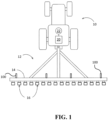
- FIG. 1 is a simplified top view illustrating a tractor 10 drawing an agricultural implement 12, e.g., a tillage implement, comprising a drawbar 14 supporting tilling assemblies 16 or other tools.
- An implement monitor 20 which may include a central processing unit (“CPU”), memory, and graphical user interface (“GUI”) (e.g., a touch-screen interface), is typically located in the cab of the tractor 10, but may be located elsewhere.
- a global positioning system (“GPS”) receiver 22 may be mounted to the tractor 10 and connected to communicate with the monitor 20.
- GPS global positioning system
- the tractor 10 or the implement 12 may carry one or more apparatus 100 for measuring soil conditions.
- the apparatus 100 may be coupled to the drawbar 14.
- the apparatus 100 may be coupled directly to a hitch of the tractor 10, or to another part of the implement 12.
- the implement 12 is shown carrying four of the apparatus 100, but may carry any number of the apparatus 100 ( e.g., one, two, three, etc .).
- FIG. 2 is a simplified perspective view of the apparatus 100, which includes a shank 110 configured to engage with the drawbar 14 ( FIG. 1 ).
- the shank 110 may include mounting holes 112 for bolts or other fasteners to connect to the drawbar 14.
- the mounting holes 112 may optionally be used to connect to any other selected tool, or to another mount point.
- the shank 110 may be mounted to a set of parallel arms and a gauge wheel to set the depth of the shank 110 in the soil.
- the shank 110 may have generally parallel lateral surfaces 114 and tapered leading surfaces 116 (only one of each surface 114, 116 is depicted in FIG. 1 ). In use, the shank 110 may typically travel through the soil in a travel direction T parallel to the lateral surfaces 114.
- the shank 110 may carry an array of movable pads 120 on one or both lateral surfaces 114. Each of the movable pads 120 may be spaced along the shank 110 at different distances from the end of the shank 110 or from the engagement point of the shank 110 with the drawbar. If the shank 110 has movable pads 120 on both lateral surfaces 114, the movable pads 120 on one side may be offset from the movable pads 120 on the opposite side of the shank 110 so that each movable pad 120 is a different distance from the end of the shank 110, which distances correspond to different depths in the soil.
- the shank 110 may also carry a strain gauge 122 or load cell configured to measure a total draft force acting on the shank 110. Though depicted on one lateral surface 114, the strain gauge 122 may be located anywhere on the apparatus 100.
- FIG. 3 is a simplified cross-sectional view of the shank 110 along line 3-3 of FIG. 2 , and which shows movable pads 120 spaced on both sides of the shank 110.
- the movable pads 120 are spaced one inch (2.54 cm) apart from one another on each lateral surface 114 of the shank 110, the vertical distance between adjacent movable pads 120 on opposite lateral surfaces 114 may be one-half inch (1.27 cm).
- the movable pads 120 may be formed of a hard, wear-resistant material, such as a polymer, a metal, a composite, etc.
- the shank 110 may also carry a plurality of sensors 130, each coupled to one of the movable pads 120, and configured to detect the deflection of the movable pads 120.
- the sensors 130 may be located behind the movable pads 120, such that the movable pads 120 protect the sensors 130 from contact with dirt and debris.
- Each sensor 130 may be configured to generate a signal corresponding to the deflection of a respective movable pad 120.
- the sensors 130 may be load cells, strain gauges, pressure sensors, or any other selected sensors.
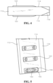
- FIG. 4 is a simplified bottom view of the shank 110, and depicts the movable pads 120 extending outward past the lateral surfaces 114 thereof.
- the movable pads 120 may have curved or tapered front surfaces to enable the shank 110 to travel through the soil without binding the movable pads 120 on the soil.
- FIG. 5 is a simplified perspective view of a portion of the shank 110 with one of the movable pads 120 removed.
- elastic pads 132 may be disposed within pockets 134 in the shank 110.
- the elastic pads 132 may enable the movable pads 120 and the sensors 130 to move within the pockets 134.
- the elastic pads 132 may optionally transfer loads from the soil to the sensors 130.
- the elastic pads 132 may simply allow movement of the movable pads 120, and another mechanism may transfer loads to the elastic pads 132.
- the movable pads 120 may be retained in the pockets 134 by flange bolts 136 ( FIG. 1 ) or other fasteners.
- FIG. 6 is a simplified side cross section of the shank 110 showing one movable pad 120, one sensor 130, and two elastic pads 132 within a pocket 134 of the shank 110.
- the movable pads 120 may be slidingly coupled to the shank 110 with the flange bolts 136 to enable the movable pads 120 to move inward and outward relative to the lateral surface 114.
- Seals 142 may be disposed between the movable pads 120 and the shank 110 to keep dirt and debris out of the space between the movable pads 120 and the shank 110.
- the seals 142 may include an O-ring, a gasket, or another seal.
- the seals 142 may be formed of an elastomeric material (e.g., natural or synthetic rubber), a hard polymer, etc.
- the movable pad 120 may directly contact the sensor 130, such that a force applied by the soil to the movable pad 120 may be transferred to the sensor 130.
- the elastic pads 132 may urge the movable pad 120 outward when the force of the soil decreases ( e.g ., when the shank 110 is removed from the soil, or when softer soil is encountered).
- FIG. 7 is a simplified side cross section of a portion of the shank 110 illustrating another way the movable pad 120 may be coupled to the sensor 130.
- the movable pad 120 may press directly on the elastic pads 132. This force deforms the elastic pads 132, which therefore apply a force on the sensor 130. That is, the movable pad 120 may apply a compressive strain to the elastic pads 132, and the elastic pads 132 exert a stress in response, which stress pushes on the sensor 130.
- FIG. 8 is a simplified side cross section illustrating another way the movable pad 120 may be coupled to the sensor 130.
- the movable pad 120 may pivot about a hinged joint 150, and one end of the movable pad 120 may press on an elastic pad 132 (as shown in FIG. 8 ) or directly on the sensor 130 (e.g., as shown in FIG. 6 ).
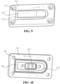
- FIG. 9 illustrates an embodiment in which a movable pad 120 is coupled to a base plate 124 by a seal 142.
- the base plate 124 may have mounting holes 126 to enable each base plate 124 to be individually secured to the shank 110 (and thus, individually replaced, in the event one movable pad 120 becomes damaged).
- FIG. 10 illustrates a view of the opposite side of the base plate 124 and the movable pad 120.
- the seal 142 may be bonded to the movable pad 120 and/or the base plate 124 to provide structure and a fluid-tight seal.
- the seal 142 may flex enough to enable the movable pad 120 to move freely inward and outward, yet may still prevent soil from entering between the base plate 124 and the movable pad 120.
- the movable pad 120 may a void 123 shaped to receive the sensor 130 ( see, e.g., FIG. 5 ).
- the movable pad 120 may also define one or more holes 125 shaped to receive alignment pins protruding from the shank 110, which may enable the movable pad 120 to move inward toward and outward from the shank 110, while preventing fore-and-aft, vertical, and twisting movement.
- the holes 125 and alignment pins may help isolate movement other than movement inward and outward.
- the implement monitor 20 of the tractor 10 may include a receiver (e.g., wired or wireless) configured to receive signals from the sensors 130.
- the implement monitor 20 may calculate a property of the soil, such as soil hardness.
- the implement monitor 20 may also include a transmitter configured to transmit the property of the soil, such as to a controller, another vehicle, a network (e.g., the internet), etc.
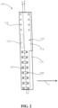
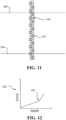
- FIG. 11 is a simplified cross-sectional view of the shank 110 traveling through soil.
- a portion of the shank 110 is below a surface 190 of the soil, including at least some of the movable pads 120.
- the sensors 130 FIG. 5 ) measure deflection of the movable pads 120 and calculate forces on the movable pads 120. Because the movable pads 120 are arranged in an array with known locations, the implement monitor 20 ( FIG. 1 ) may correlate the force on the movable pads 120 to a depth in the soil, visualized in the graph 192 shown in FIG. 12 .
- the soil density generally increases with depth, and a point 194 at which the slope of the graph 192 changes may identify a depth of a compaction layer 196 or hard pan.
- Identification of the compaction layer 196 may enable a farmer to change tillage, seeding, fertilizing, watering, or other parameters, at the time of the measurement or at any later time.
- the implement monitor 20 may generate a map of a field with depth of the compaction layer 196, which may be used to identify portions of the field for additional tilling, different seed populations, different seed depths, etc.
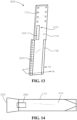
- FIG. 13 is a simplified perspective view of another apparatus 200, which includes a shank 210 configured to engage with the drawbar 14 ( FIG. 1 ) via mounting holes 112.
- the mounting holes 112 may optionally be used to connect to any other selected tool, or to another mount point.
- the shank 110 may have generally parallel lateral surfaces 114 and tapered leading surfaces 116 (only one of each surface 114, 116 is depicted in FIG. 1 ).
- the shank 210 may carry an array of movable pads 220 along the rear of the shank 210, rearward of the lateral surfaces 114.
- the shank 210 may also carry a strain gauge 122 or load cell configured to measure a total draft force acting on the shank 210.
- FIG. 14 is a simplified cross-sectional view of the shank 210 along line 14-14 of FIG. 13 , and which shows that the movable pad 220 along the rear of the shank 210 may be flared outward past the lateral surfaces 114, such as in a generally trapezoidal shape.
- the movable pads 220 in this embodiment may measure draft forces (i.e., the force required to drag the movable pads 220 through the soil), rather than compressive forces, which may be measured by the apparatus 100 shown in FIG. 2 . As soil density increases, draft force also increases. The angle and length of the surfaces of the movable pads 220 may affect the draft force applied to the movable pads 220.
- the movable pads 220 may be connected to the shank 110 by a load cell 230, which is in tension when the shank 110 is dragged through soil.
- the shank 110 may also carry a plurality of sensors 130, each coupled to one of the movable pads 120, and configured to detect the deflection of the movable pads 120.
- the sensors 130 may be located behind the movable pads 120, such that the movable pads 120 protect the sensors 130 from contact with dirt and debris.
- Each sensor 130 may be configured to generate a signal corresponding to the deflection of a respective movable pad 120.
- the sensors 130 may be load cells, strain gauges, pressure sensors, or any other selected sensors.
- FIG. 15 is a simplified flow chart illustrating a method 300 of measuring a property of soil.
- Block 302 represents dragging a shank through soil, such as the shank 110 shown and described above.
- Block 304 represents measuring deflection of movable pads relative to the shank as the shank is dragged through the soil using sensors coupled to the movable pads.
- signals related to the deflection of the movable pads are generated with the sensors.
- the draft force on each movable pad is calculated. Alternatively, a compressive force on each movable pad may be calculated.
- the sum of the draft forces on each movable pad is compared to the total draft force on the shank. This may be used to calibrate the apparatus or verify proper operation of the apparatus.
- soil compaction is calculated as a function of depth in the soil.
- a depth of a compaction layer of the soil is calculated.
Landscapes
- Life Sciences & Earth Sciences (AREA)
- Engineering & Computer Science (AREA)
- Health & Medical Sciences (AREA)
- Chemical & Material Sciences (AREA)
- Mechanical Engineering (AREA)
- Soil Sciences (AREA)
- Environmental Sciences (AREA)
- Environmental & Geological Engineering (AREA)
- Analytical Chemistry (AREA)
- Geology (AREA)
- General Life Sciences & Earth Sciences (AREA)
- Food Science & Technology (AREA)
- Medicinal Chemistry (AREA)
- Physics & Mathematics (AREA)
- Remote Sensing (AREA)
- Biochemistry (AREA)
- General Health & Medical Sciences (AREA)
- General Physics & Mathematics (AREA)
- Immunology (AREA)
- Pathology (AREA)
- Force Measurement Appropriate To Specific Purposes (AREA)
Claims (15)
- Vorrichtung (100) zum Messen einer Bodenbeschaffenheit, wobei die Vorrichtung (100) aufweist:einen Schaft (110), der dazu ausgebildet ist, mit einer Deichsel (14) aneinander anzugreifen;einem Array von beweglichen Kontaktelementen (120), die von dem Schaft (110) getragen sind, wobei die beweglichen Kontaktelemente (120) jeweils in unterschiedlichen Entfernungen von einem Punkt beabstandet sind, an welchem der Schaft (110) ausgebildet ist, an der Deichsel (14) anzugreifen; undeiner Mehrzahl von Sensoren (130), wobei jeder Sensor mit mindestens einem beweglichen Kontaktelement des Arrays von beweglichen Kontaktelementen (120) gekoppelt ist und ausgebildet ist, eine Auslenkung des mindestens einen beweglichen Kontaktelements relativ zu dem Schaft (110) zu messen, wenn der Schaft (110) von der Deichsel (14) durch den Boden gezogen wird;dadurch gekennzeichnet, dassdie beweglichen Kontaktelemente (120) des Arrays an oder über einer lateralen Oberfläche des Schafts (110) angeordnet sind.
- Vorrichtung (100) nach Anspruch 1, wobei jeder Sensor ausgebildet ist, ein zu der gemessenen Auslenkung korrespondierendes Signal zu generieren.
- Vorrichtung (100) nach Anspruch 2, weiterhin mit einem Empfänger, der in Kommunikation mit den Sensoren (130) steht, wobei der Empfänger ausgebildet ist, die Signale von den Sensoren (130) zu empfangen.
- Vorrichtung (100) nach Anspruch 3, weiterhin mit einem Prozessor, der ausgebildet ist, eine Eigenschaft des Bodens zu berechnen.
- Vorrichtung (100) nach einem der Ansprüche 1 bis 4, wobei die Sensoren (130) Dehnungsmessstreifen aufweisen.
- Vorrichtung (100) nach einem der Ansprüche 1 bis 4, wobei die beweglichen Kontaktelemente (120) gelenkig an den Schaft (110) gekoppelt sind.
- Vorrichtung (100) nach einem der Ansprüche 1 bis 4, wobei die beweglichen Kontaktelemente (120) verschiebbar an den Schaft (110) gekoppelt sind.
- Vorrichtung (100) nach einem der Ansprüche 1 bis 4, weiterhin mit:einem zweiten Array von beweglichen Kontaktelementen auf oder über einer der ersten lateralen Oberfläche gegenüberliegenden zweiten lateralen Oberfläche des Schafts (110); undeiner zweiten Mehrzahl von Sensoren, wobei jeder Sensor mit mindestens einem beweglichen Kontaktelement des zweiten Arrays von beweglichen Kontaktelementen gekoppelt ist und ausgebildet ist, die Auslenkung des mindestens einen beweglichen Kontaktelements relativ zu dem Schaft (110) zu messen, wenn der Schaft (110) durch den Boden gezogen wird.
- Vorrichtung (100) nach Anspruch 8, wobei die beweglichen Kontaktelemente des zweiten Arrays jeweils zu den beweglichen Kontaktelementen des Arrays versetzt sind.
- Verfahren zum Messen einer Bodeneigenschaft, wobei das Verfahren aufweist:Ziehen eines Schafts (110) durch einen Boden, wobei der Schaft (110) ein Array von beweglichen Kontaktelementen trägt, wobei die beweglichen Kontaktelemente jeweils in unterschiedlichen Entfernungen von einer Deichsel (14) beabstandet sind, die an dem Schaft (110) angreift, wobei die beweglichen Kontaktelemente des Arrays an oder über einer lateralen Oberfläche des Schafts (110) angeordnet sind; undMessen einer Auslenkung der beweglichen Kontaktelemente relativ zu dem Schaft (110), wenn der Schaft (110) durch den Boden gezogen wird, unter Verwenden einer Mehrzahl von Sensoren (130), die mit den beweglichen Kontaktelementen gekoppelt sind.
- Verfahren nach Anspruch 10, weiterhin mit Generieren von Signalen mit den Sensoren (130), wobei sich die Signale auf die Auslenkung der beweglichen Kontaktstellen beziehen.
- Verfahren nach Anspruch 10 oder Anspruch 11, weiterhin mit Berechnen einer Bodenverdichtung des Bodens als Funktion der Tiefe.
- Verfahren nach Anspruch 12, weiterhin mit Berechnen einer Tiefe einer Verdichtungsschicht des Bodens.
- Verfahren nach Anspruch 10 oder Anspruch 11, weiterhin mit Berechnen einer Zugkraft auf jedes der beweglichen Kontaktelemente.
- Verfahren nach Anspruch 14, weiterhin mit Vergleichen einer Summe der Zugkräfte auf jedes der beweglichen Kontaktelemente mit einer Gesamtzugkraft auf den Schaft (110).
Applications Claiming Priority (2)
| Application Number | Priority Date | Filing Date | Title |
|---|---|---|---|
| US202063047581P | 2020-07-02 | 2020-07-02 | |
| PCT/IB2021/055112 WO2022003460A1 (en) | 2020-07-02 | 2021-06-10 | Apparatus and methods for measuring soil conditions |
Publications (2)
| Publication Number | Publication Date |
|---|---|
| EP4175451A1 EP4175451A1 (de) | 2023-05-10 |
| EP4175451B1 true EP4175451B1 (de) | 2024-10-23 |
Family
ID=76502763
Family Applications (1)
| Application Number | Title | Priority Date | Filing Date |
|---|---|---|---|
| EP21733202.2A Active EP4175451B1 (de) | 2020-07-02 | 2021-06-10 | Geräte und methoden zur messung der bodenbeschaffenheit |
Country Status (3)
| Country | Link |
|---|---|
| US (1) | US12239038B2 (de) |
| EP (1) | EP4175451B1 (de) |
| WO (1) | WO2022003460A1 (de) |
Families Citing this family (2)
| Publication number | Priority date | Publication date | Assignee | Title |
|---|---|---|---|---|
| WO2020208431A1 (en) * | 2019-04-11 | 2020-10-15 | Precision Planting Llc | Apparatus and methods for measuring soil conditions |
| EP4175451B1 (de) | 2020-07-02 | 2024-10-23 | Precision Planting LLC | Geräte und methoden zur messung der bodenbeschaffenheit |
Family Cites Families (42)
| Publication number | Priority date | Publication date | Assignee | Title |
|---|---|---|---|---|
| US4554819A (en) | 1983-09-28 | 1985-11-26 | Ali Muhammad A | Method of and apparatus for measuring in situ, the subsurface bearing strength, the skin friction, and other subsurface characteristics of the soil |
| US4579003A (en) | 1985-01-22 | 1986-04-01 | Riley Brodie D | Instrument for testing earthen samples under triaxial load conditions |
| SU1264065A1 (ru) | 1985-05-06 | 1986-10-15 | Научно-производственное объединение по механизации и электрификации сельского хозяйства "Целинсельхозмеханизация" | Устройство дл непрерывного определени твердости солонцовых почв |
| SU1474546A1 (ru) | 1987-01-29 | 1989-04-23 | Кировоградский Проектно-Конструкторский Институт По Почвообрабатывающим И Посевным Машинам | Прибор дл определени фронтального сопротивлени почвы |
| US4909335A (en) | 1989-05-16 | 1990-03-20 | Walt Jr Ted | Deep tillage shank system |
| US5524560A (en) | 1994-12-09 | 1996-06-11 | The United States Of America As Represented By The Department Of Agriculture | System for controlling vertical displacement of agricultural implements into the soil |
| US5726349A (en) | 1995-05-18 | 1998-03-10 | United States Army Corps Of Engineers As Represented By The Secretary Of The Army | Automated cone penetrometer |
| US6062090A (en) | 1996-07-31 | 2000-05-16 | Transportation Technology Center, Inc. | Apparatus and method for determining the strength and type of soil |
| US5797460A (en) | 1996-10-22 | 1998-08-25 | Deere & Company | Straight bar tillage implement |
| US6041582A (en) | 1998-02-20 | 2000-03-28 | Case Corporation | System for recording soil conditions |
| CN1057363C (zh) | 1998-07-10 | 2000-10-11 | 贺德新 | 一种液压挤扩装置 |
| WO2001004627A1 (en) | 1999-07-08 | 2001-01-18 | Omron Corporation | Soil measuring instrument, soil measurement assisting device and method, recorded medium on which program is recorded, recorded medium on which data is recorded, application amount controller, application amount determining device, method for them, and farm working determination assisting system |
| US6497153B1 (en) | 2000-09-28 | 2002-12-24 | Bechtel Bwxt Idaho, Llc | Measuring spatial variability in soil characteristics |
| US6853937B2 (en) * | 2001-07-06 | 2005-02-08 | Tokyo University Of Agriculture And Technology Tlo Co., Ltd. | Soil characteristics survey device and soil characteristics survey method |
| US20030016029A1 (en) | 2001-07-18 | 2003-01-23 | Schuler Ronald T. | Soil moisture measuring system for a mobile agricultural device |
| US6834550B2 (en) | 2001-09-10 | 2004-12-28 | The Regents Of The University Of California | Soil profile force measurement using an instrumented tine |
| US6389999B1 (en) | 2001-11-02 | 2002-05-21 | Dennis Duello | Dynamic controller of excess downpressure for surface engaging implement |
| US6647799B1 (en) | 2002-01-16 | 2003-11-18 | The United States Of America As Represented By The Secretary Of Agriculture | Soil strength measurement for site-specific agriculture |
| US6688243B1 (en) | 2002-08-28 | 2004-02-10 | The Mcgregor Company | Minimum tillage agricultural implement having furrow opening shank assemblies |
| US6701857B1 (en) | 2003-01-16 | 2004-03-09 | Lynn David Jensen | Depth control device for planting implement |
| US7762345B2 (en) | 2003-03-05 | 2010-07-27 | Salford Farm Machinery Ltd. | Conservation tillage implement, system and method |
| US7028554B2 (en) * | 2003-07-11 | 2006-04-18 | Deere & Company | Instrumented deep tillage implement |
| US7299686B2 (en) | 2004-03-02 | 2007-11-27 | The Texas A&M University System | System and method for testing the compaction of soil |
| US20070272134A1 (en) | 2006-05-23 | 2007-11-29 | Christopher John Baker | Ground opening device |
| WO2008086283A2 (en) | 2007-01-08 | 2008-07-17 | Precision Planting Inc. | Load sensing pin |
| US20080267719A1 (en) | 2007-04-24 | 2008-10-30 | Caterpillar Inc. | Towed compaction determination system utilizing drawbar force |
| ES2339315B1 (es) | 2008-03-11 | 2011-03-11 | Universidad De Cordoba | Sistema para la medida "in situ" de la resistencia al corte y la fuerza de friccion en suelos. |
| US8827001B2 (en) | 2012-01-17 | 2014-09-09 | Cnh Industrial America Llc | Soil monitoring system |
| GB2500198B (en) | 2012-03-12 | 2014-06-18 | Frontier Agriculture Ltd | Soil cultivation system |
| US20140204083A1 (en) | 2013-01-23 | 2014-07-24 | Brent Thomson | Systems and methods for real-time distortion processing |
| NO336857B1 (no) | 2014-01-16 | 2015-11-16 | Kverneland Group Operations As | Arrangement og framgangsmåte for flertrinns dypbearbeiding av jordsmonn |
| DE102014115209A1 (de) | 2014-10-20 | 2016-04-21 | Amazonen-Werke H. Dreyer Gmbh & Co. Kg | Bodenbearbeitungswerkzeug |
| WO2016162311A1 (de) | 2015-04-07 | 2016-10-13 | Betek Gmbh & Co. Kg | Bodenbearbeitungssystem |
| UA124190C2 (uk) | 2015-06-15 | 2021-08-04 | Пресіжн Плентінг Елелсі | Системи, способи і пристрої внесення сільськогосподарської рідини |
| DE102015111518A1 (de) * | 2015-07-16 | 2017-01-19 | Amazonen-Werke H. Dreyer Gmbh & Co. Kg | Bodenbearbeitungsgerät und Verfahren zur Erstellung einer Bodenkarte mit einem derartigen Bodenbearbeitungsgerät |
| US20180232674A1 (en) | 2015-11-05 | 2018-08-16 | Agco International Gmbh | Method and system for determining work trajectories for a fleet of working units in a harvest operation |
| US10383272B2 (en) | 2016-12-07 | 2019-08-20 | Cnh Industrial America Llc | Tillage and fertilizer knife attachment method |
| US10178823B2 (en) | 2016-12-12 | 2019-01-15 | Cnh Industrial Canada, Ltd. | Agricultural implement with automatic shank depth control |
| CA3047779A1 (en) | 2016-12-19 | 2018-06-28 | The Climate Corporation | Systems, methods and apparatus for soil and seed monitoring |
| WO2020113284A1 (en) | 2018-12-07 | 2020-06-11 | Sensortine Pty Ltd | Methods and apparatus for agriculture |
| CN109633127B (zh) | 2019-01-24 | 2024-06-04 | 山东省农业机械科学研究院 | 一种土壤压实度测定机构、装置及方法 |
| EP4175451B1 (de) | 2020-07-02 | 2024-10-23 | Precision Planting LLC | Geräte und methoden zur messung der bodenbeschaffenheit |
-
2021
- 2021-06-10 EP EP21733202.2A patent/EP4175451B1/de active Active
- 2021-06-10 WO PCT/IB2021/055112 patent/WO2022003460A1/en not_active Ceased
- 2021-06-10 US US17/998,408 patent/US12239038B2/en active Active
Also Published As
| Publication number | Publication date |
|---|---|
| WO2022003460A1 (en) | 2022-01-06 |
| US20230172092A1 (en) | 2023-06-08 |
| US12239038B2 (en) | 2025-03-04 |
| EP4175451A1 (de) | 2023-05-10 |
Similar Documents
| Publication | Publication Date | Title |
|---|---|---|
| US12120971B2 (en) | Apparatus, system and method for monitoring soil criteria during tillage operations and control of tillage tools | |
| US10548254B2 (en) | Load sensing pin for an agricultural implement | |
| US20120125244A1 (en) | Mapping soil hardness | |
| EP4175451B1 (de) | Geräte und methoden zur messung der bodenbeschaffenheit | |
| Chethan et al. | Transducers for measurement of draft and torque of tractor-implement system—a review | |
| US6497153B1 (en) | Measuring spatial variability in soil characteristics | |
| Hanquet et al. | Analysis of soil variability measured with a soil strength sensor | |
| Alimardani et al. | Design and development of a three-point hitch dynamometer | |
| US20220091089A1 (en) | Apparatus and methods for measuring soil conditions | |
| CN204346690U (zh) | 免耕深松施肥播种机土壤工作部件测试装置 | |
| Hemmat et al. | Use of an instrumented disc coulter for mapping soil mechanical resistance | |
| Chung et al. | On-the-go soil strength profile sensor using a load cell array | |
| Adamchuk et al. | An integrated system for mapping soil physical properties on the-go: the mechanical sensing component | |
| Liu | Parameters optimisation of agricultural machinery for soil compaction mitigation and crop yield enhancement | |
| Kirisci | A field method for predicting the draught forces of tillage implements. | |
| Atanasov et al. | Cultivator-based soil density measurement method | |
| EP3953705B1 (de) | Vorrichtung und verfahren zur messung von bodenbedingungen | |
| Smith | The effect of agricultural traffic and tillage on soil physical properties and crop yields | |
| Jabro et al. | Spatial and temporal variability of soil penetration resistance transecting sugarbeet rows and inter-rows in tillage systems | |
| Odey et al. | Instrumentation Assembly for Measuring Draughts ofSubsoilersin Outdoor Soil Bin Facility | |
| Raheman et al. | Measurement of parameters for performance evaluation of tillage implements | |
| Kumar et al. | Sensors for Soil Hard Pan Determination-A Review | |
| WO2020208430A1 (en) | Tillage implements and methods of identifying a compaction layer | |
| Keen et al. | Force measurement between a tractor and a three point linkage mounted cultivation implement | |
| Stafford | Precision tillage systems Pedro Andrade-Sanchez, University of Arizona, USA; and Shrinivasa K. Upadhyaya, University of California-Davis, USA |
Legal Events
| Date | Code | Title | Description |
|---|---|---|---|
| STAA | Information on the status of an ep patent application or granted ep patent |
Free format text: STATUS: UNKNOWN |
|
| STAA | Information on the status of an ep patent application or granted ep patent |
Free format text: STATUS: THE INTERNATIONAL PUBLICATION HAS BEEN MADE |
|
| PUAI | Public reference made under article 153(3) epc to a published international application that has entered the european phase |
Free format text: ORIGINAL CODE: 0009012 |
|
| STAA | Information on the status of an ep patent application or granted ep patent |
Free format text: STATUS: REQUEST FOR EXAMINATION WAS MADE |
|
| 17P | Request for examination filed |
Effective date: 20230202 |
|
| AK | Designated contracting states |
Kind code of ref document: A1 Designated state(s): AL AT BE BG CH CY CZ DE DK EE ES FI FR GB GR HR HU IE IS IT LI LT LU LV MC MK MT NL NO PL PT RO RS SE SI SK SM TR |
|
| DAV | Request for validation of the european patent (deleted) | ||
| DAX | Request for extension of the european patent (deleted) | ||
| GRAP | Despatch of communication of intention to grant a patent |
Free format text: ORIGINAL CODE: EPIDOSNIGR1 |
|
| STAA | Information on the status of an ep patent application or granted ep patent |
Free format text: STATUS: GRANT OF PATENT IS INTENDED |
|
| GRAS | Grant fee paid |
Free format text: ORIGINAL CODE: EPIDOSNIGR3 |
|
| GRAA | (expected) grant |
Free format text: ORIGINAL CODE: 0009210 |
|
| STAA | Information on the status of an ep patent application or granted ep patent |
Free format text: STATUS: THE PATENT HAS BEEN GRANTED |
|
| INTG | Intention to grant announced |
Effective date: 20240821 |
|
| AK | Designated contracting states |
Kind code of ref document: B1 Designated state(s): AL AT BE BG CH CY CZ DE DK EE ES FI FR GB GR HR HU IE IS IT LI LT LU LV MC MK MT NL NO PL PT RO RS SE SI SK SM TR |
|
| REG | Reference to a national code |
Ref country code: GB Ref legal event code: FG4D |
|
| REG | Reference to a national code |
Ref country code: CH Ref legal event code: EP |
|
| REG | Reference to a national code |
Ref country code: DE Ref legal event code: R096 Ref document number: 602021020665 Country of ref document: DE |
|
| REG | Reference to a national code |
Ref country code: IE Ref legal event code: FG4D |
|
| REG | Reference to a national code |
Ref country code: LT Ref legal event code: MG9D |
|
| REG | Reference to a national code |
Ref country code: NL Ref legal event code: MP Effective date: 20241023 |
|
| REG | Reference to a national code |
Ref country code: AT Ref legal event code: MK05 Ref document number: 1733999 Country of ref document: AT Kind code of ref document: T Effective date: 20241023 |
|
| PG25 | Lapsed in a contracting state [announced via postgrant information from national office to epo] |
Ref country code: NL Free format text: LAPSE BECAUSE OF FAILURE TO SUBMIT A TRANSLATION OF THE DESCRIPTION OR TO PAY THE FEE WITHIN THE PRESCRIBED TIME-LIMIT Effective date: 20241023 |
|
| PG25 | Lapsed in a contracting state [announced via postgrant information from national office to epo] |
Ref country code: NL Free format text: LAPSE BECAUSE OF FAILURE TO SUBMIT A TRANSLATION OF THE DESCRIPTION OR TO PAY THE FEE WITHIN THE PRESCRIBED TIME-LIMIT Effective date: 20241023 |
|
| PG25 | Lapsed in a contracting state [announced via postgrant information from national office to epo] |
Ref country code: IS Free format text: LAPSE BECAUSE OF FAILURE TO SUBMIT A TRANSLATION OF THE DESCRIPTION OR TO PAY THE FEE WITHIN THE PRESCRIBED TIME-LIMIT Effective date: 20250223 Ref country code: PT Free format text: LAPSE BECAUSE OF FAILURE TO SUBMIT A TRANSLATION OF THE DESCRIPTION OR TO PAY THE FEE WITHIN THE PRESCRIBED TIME-LIMIT Effective date: 20250224 Ref country code: HR Free format text: LAPSE BECAUSE OF FAILURE TO SUBMIT A TRANSLATION OF THE DESCRIPTION OR TO PAY THE FEE WITHIN THE PRESCRIBED TIME-LIMIT Effective date: 20241023 |
|
| PG25 | Lapsed in a contracting state [announced via postgrant information from national office to epo] |
Ref country code: FI Free format text: LAPSE BECAUSE OF FAILURE TO SUBMIT A TRANSLATION OF THE DESCRIPTION OR TO PAY THE FEE WITHIN THE PRESCRIBED TIME-LIMIT Effective date: 20241023 |
|
| PG25 | Lapsed in a contracting state [announced via postgrant information from national office to epo] |
Ref country code: BG Free format text: LAPSE BECAUSE OF FAILURE TO SUBMIT A TRANSLATION OF THE DESCRIPTION OR TO PAY THE FEE WITHIN THE PRESCRIBED TIME-LIMIT Effective date: 20241023 |
|
| PG25 | Lapsed in a contracting state [announced via postgrant information from national office to epo] |
Ref country code: ES Free format text: LAPSE BECAUSE OF FAILURE TO SUBMIT A TRANSLATION OF THE DESCRIPTION OR TO PAY THE FEE WITHIN THE PRESCRIBED TIME-LIMIT Effective date: 20241023 |
|
| PG25 | Lapsed in a contracting state [announced via postgrant information from national office to epo] |
Ref country code: NO Free format text: LAPSE BECAUSE OF FAILURE TO SUBMIT A TRANSLATION OF THE DESCRIPTION OR TO PAY THE FEE WITHIN THE PRESCRIBED TIME-LIMIT Effective date: 20250123 |
|
| PG25 | Lapsed in a contracting state [announced via postgrant information from national office to epo] |
Ref country code: GR Free format text: LAPSE BECAUSE OF FAILURE TO SUBMIT A TRANSLATION OF THE DESCRIPTION OR TO PAY THE FEE WITHIN THE PRESCRIBED TIME-LIMIT Effective date: 20250124 Ref country code: LV Free format text: LAPSE BECAUSE OF FAILURE TO SUBMIT A TRANSLATION OF THE DESCRIPTION OR TO PAY THE FEE WITHIN THE PRESCRIBED TIME-LIMIT Effective date: 20241023 Ref country code: AT Free format text: LAPSE BECAUSE OF FAILURE TO SUBMIT A TRANSLATION OF THE DESCRIPTION OR TO PAY THE FEE WITHIN THE PRESCRIBED TIME-LIMIT Effective date: 20241023 |
|
| PG25 | Lapsed in a contracting state [announced via postgrant information from national office to epo] |
Ref country code: PL Free format text: LAPSE BECAUSE OF FAILURE TO SUBMIT A TRANSLATION OF THE DESCRIPTION OR TO PAY THE FEE WITHIN THE PRESCRIBED TIME-LIMIT Effective date: 20241023 |
|
| PG25 | Lapsed in a contracting state [announced via postgrant information from national office to epo] |
Ref country code: RS Free format text: LAPSE BECAUSE OF FAILURE TO SUBMIT A TRANSLATION OF THE DESCRIPTION OR TO PAY THE FEE WITHIN THE PRESCRIBED TIME-LIMIT Effective date: 20250123 |
|
| PG25 | Lapsed in a contracting state [announced via postgrant information from national office to epo] |
Ref country code: SM Free format text: LAPSE BECAUSE OF FAILURE TO SUBMIT A TRANSLATION OF THE DESCRIPTION OR TO PAY THE FEE WITHIN THE PRESCRIBED TIME-LIMIT Effective date: 20241023 |
|
| PGFP | Annual fee paid to national office [announced via postgrant information from national office to epo] |
Ref country code: DE Payment date: 20250618 Year of fee payment: 5 |
|
| PG25 | Lapsed in a contracting state [announced via postgrant information from national office to epo] |
Ref country code: DK Free format text: LAPSE BECAUSE OF FAILURE TO SUBMIT A TRANSLATION OF THE DESCRIPTION OR TO PAY THE FEE WITHIN THE PRESCRIBED TIME-LIMIT Effective date: 20241023 |
|
| PG25 | Lapsed in a contracting state [announced via postgrant information from national office to epo] |
Ref country code: EE Free format text: LAPSE BECAUSE OF FAILURE TO SUBMIT A TRANSLATION OF THE DESCRIPTION OR TO PAY THE FEE WITHIN THE PRESCRIBED TIME-LIMIT Effective date: 20241023 |
|
| PGFP | Annual fee paid to national office [announced via postgrant information from national office to epo] |
Ref country code: FR Payment date: 20250627 Year of fee payment: 5 |
|
| PG25 | Lapsed in a contracting state [announced via postgrant information from national office to epo] |
Ref country code: RO Free format text: LAPSE BECAUSE OF FAILURE TO SUBMIT A TRANSLATION OF THE DESCRIPTION OR TO PAY THE FEE WITHIN THE PRESCRIBED TIME-LIMIT Effective date: 20241023 |
|
| REG | Reference to a national code |
Ref country code: DE Ref legal event code: R097 Ref document number: 602021020665 Country of ref document: DE |
|
| PG25 | Lapsed in a contracting state [announced via postgrant information from national office to epo] |
Ref country code: SK Free format text: LAPSE BECAUSE OF FAILURE TO SUBMIT A TRANSLATION OF THE DESCRIPTION OR TO PAY THE FEE WITHIN THE PRESCRIBED TIME-LIMIT Effective date: 20241023 |
|
| PG25 | Lapsed in a contracting state [announced via postgrant information from national office to epo] |
Ref country code: CZ Free format text: LAPSE BECAUSE OF FAILURE TO SUBMIT A TRANSLATION OF THE DESCRIPTION OR TO PAY THE FEE WITHIN THE PRESCRIBED TIME-LIMIT Effective date: 20241023 |
|
| PG25 | Lapsed in a contracting state [announced via postgrant information from national office to epo] |
Ref country code: IT Free format text: LAPSE BECAUSE OF FAILURE TO SUBMIT A TRANSLATION OF THE DESCRIPTION OR TO PAY THE FEE WITHIN THE PRESCRIBED TIME-LIMIT Effective date: 20241023 |
|
| PLBE | No opposition filed within time limit |
Free format text: ORIGINAL CODE: 0009261 |
|
| STAA | Information on the status of an ep patent application or granted ep patent |
Free format text: STATUS: NO OPPOSITION FILED WITHIN TIME LIMIT |
|
| PG25 | Lapsed in a contracting state [announced via postgrant information from national office to epo] |
Ref country code: SE Free format text: LAPSE BECAUSE OF FAILURE TO SUBMIT A TRANSLATION OF THE DESCRIPTION OR TO PAY THE FEE WITHIN THE PRESCRIBED TIME-LIMIT Effective date: 20241023 |
|
| 26N | No opposition filed |
Effective date: 20250724 |
|
| REG | Reference to a national code |
Ref country code: DE Ref legal event code: R084 Ref document number: 602021020665 Country of ref document: DE |
|
| REG | Reference to a national code |
Ref country code: CH Ref legal event code: H13 Free format text: ST27 STATUS EVENT CODE: U-0-0-H10-H13 (AS PROVIDED BY THE NATIONAL OFFICE) Effective date: 20260127 |
|
| PG25 | Lapsed in a contracting state [announced via postgrant information from national office to epo] |
Ref country code: MC Free format text: LAPSE BECAUSE OF FAILURE TO SUBMIT A TRANSLATION OF THE DESCRIPTION OR TO PAY THE FEE WITHIN THE PRESCRIBED TIME-LIMIT Effective date: 20241023 |