EP3953705B1 - Vorrichtung und verfahren zur messung von bodenbedingungen - Google Patents
Vorrichtung und verfahren zur messung von bodenbedingungen Download PDFInfo
- Publication number
- EP3953705B1 EP3953705B1 EP20708639.8A EP20708639A EP3953705B1 EP 3953705 B1 EP3953705 B1 EP 3953705B1 EP 20708639 A EP20708639 A EP 20708639A EP 3953705 B1 EP3953705 B1 EP 3953705B1
- Authority
- EP
- European Patent Office
- Prior art keywords
- soil
- shank
- beams
- load cells
- signals
- Prior art date
- Legal status (The legal status is an assumption and is not a legal conclusion. Google has not performed a legal analysis and makes no representation as to the accuracy of the status listed.)
- Active
Links
Images


Classifications
-
- A—HUMAN NECESSITIES
- A01—AGRICULTURE; FORESTRY; ANIMAL HUSBANDRY; HUNTING; TRAPPING; FISHING
- A01B—SOIL WORKING IN AGRICULTURE OR FORESTRY; PARTS, DETAILS, OR ACCESSORIES OF AGRICULTURAL MACHINES OR IMPLEMENTS, IN GENERAL
- A01B79/00—Methods for working soil
- A01B79/005—Precision agriculture
-
- G—PHYSICS
- G01—MEASURING; TESTING
- G01N—INVESTIGATING OR ANALYSING MATERIALS BY DETERMINING THEIR CHEMICAL OR PHYSICAL PROPERTIES
- G01N33/00—Investigating or analysing materials by specific methods not covered by groups G01N1/00 - G01N31/00
- G01N33/24—Earth materials
-
- E—FIXED CONSTRUCTIONS
- E02—HYDRAULIC ENGINEERING; FOUNDATIONS; SOIL SHIFTING
- E02D—FOUNDATIONS; EXCAVATIONS; EMBANKMENTS; UNDERGROUND OR UNDERWATER STRUCTURES
- E02D1/00—Investigation of foundation soil in situ
- E02D1/02—Investigation of foundation soil in situ before construction work
- E02D1/022—Investigation of foundation soil in situ before construction work by investigating mechanical properties of the soil
-
- G—PHYSICS
- G01—MEASURING; TESTING
- G01N—INVESTIGATING OR ANALYSING MATERIALS BY DETERMINING THEIR CHEMICAL OR PHYSICAL PROPERTIES
- G01N33/00—Investigating or analysing materials by specific methods not covered by groups G01N1/00 - G01N31/00
- G01N33/24—Earth materials
- G01N33/245—Earth materials for agricultural purposes
Definitions
- Embodiments of the present disclosure relate to measurement of soil conditions. More particularly, embodiments of the present invention relate to apparatus and methods for measuring soil compaction in conjunction with planting.
- Crop yields are affected by a variety of factors, such as seed placement, soil quality, weather, irrigation, and nutrient applications. Soil compaction affects how seeds are placed, as well as how water and fertilizer permeates the soil. Thus, tests have been developed to measure soil compaction in agricultural fields.
- soil compaction is a measure of the volume of solid material within a given volume of soil as compared to the volume of liquid or gases (e.g., in pores between particles of solid material). Soil compaction is proportional to soil density of dry soil. Information about soil compaction is valuable because it assists farmers with determining how deep to plant seeds, how much to water and fertilizer to apply, etc.
- soil compaction is related to the force required to break through soil so that seeds can be planted below the surface. Crop yield can also be affected by soil compaction. Significant changes in soil compaction or soil density in the soil profile of the root zone of a plant can adversely affect crop yield. For example, a large change in soil compaction may cause roots to change direction when they reach the soil with high compaction. Soil compaction typically varies throughout a field and with depth beneath the surface. A no-till field could have a higher soil density or soil compaction compared to tilled field, all other variables being equal, but the density and compaction of the no-till field could still be within acceptable ranges.
- the no-till field may still produce similar or better crop yield than the tilled field if rapid and significant soil density changes are minimized.
- Information about the density and compaction can help farmers make decisions about whether tilling is required or if tillage depth should increase or decrease.
- J. Agiiera et al in "Design of a Soil Cutting Resistance Sensor for Application in Site-Specific Tillage", Sensors 2013, 13, 5945-5957 , discloses a soil strength sensor for measuring soil cutting resistance at various depths while traversing a field.
- an apparatus for measuring a soil condition includes a plurality of elongate beams mounted on opposing sides of a shank and arranged at different heights along the shank, and a plurality of load cells.
- Each load cell of the plurality is coupled to the shank and to a beam of the plurality such that a horizontal force on the beam induces the load cell to generate a signal corresponding to a force on the beam.
- a method of measuring a property of soil includes dragging at least a portion of a shank through soil.
- the shank carries a plurality of elongate beams mounted on opposing sides of the shank and arranged at different heights.
- the method also includes inducing a force on each of a plurality of load cells related to horizontal forces on the plurality of beams, wherein each load cell is coupled to the shank and to a beam of the plurality.
- the method includes generating signals with the load cells. The signals are related to the forces on the load cells.
- the method may be used to measure soil compaction and/or identify a compaction layer.
- the terms “comprising,” “including,” “containing,” “characterized by,” and grammatical equivalents thereof are inclusive or open-ended terms that do not exclude additional, unrecited elements or method steps, but also include the more restrictive terms “consisting of” and “consisting essentially of” and grammatical equivalents thereof.
- the term "may” with respect to a material, structure, feature, or method act indicates that such is contemplated for use in implementation of an embodiment of the disclosure, and such term is used in preference to the more restrictive term “is” so as to avoid any implication that other, compatible materials, structures, features, and methods usable in combination therewith should or must be excluded.
- the term “configured” refers to a size, shape, material composition, and arrangement of one or more of at least one structure and at least one apparatus facilitating operation of one or more of the structure and the apparatus in a predetermined way.
- spatially relative terms such as “beneath,” “below,” “lower,” “bottom,” “above,” “upper,” “top,” “front,” “rear,” “left,” “right,” and the like, may be used for ease of description to describe one element's or feature's relationship to another element(s) or feature(s) as illustrated in the figures. Unless otherwise specified, the spatially relative terms are intended to encompass different orientations of the materials in addition to the orientation depicted in the figures.
- the term "substantially" in reference to a given parameter, property, or condition means and includes to a degree that one of ordinary skill in the art would understand that the given parameter, property, or condition is met with a degree of variance, such as within acceptable manufacturing tolerances.
- the parameter, property, or condition may be at least 90.0% met, at least 95.0% met, at least 99.0% met, or even at least 99.9% met.
- the term "about” used in reference to a given parameter is inclusive of the stated value and has the meaning dictated by the context (e.g., it includes the degree of error associated with measurement of the given parameter).
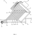
- FIG. 1 is a simplified side view of an apparatus 10 for measuring a soil condition.
- the apparatus 10 may be used to measure a force required to break through soil as a function of depth, which may be used to calculate soil compaction, or which may be used as a proxy for soil compaction.
- the apparatus 10 includes a frame 12 and a plurality of beams 14 (indicated 14a, 14b, and 14c, with others unlabeled for simplicity) carried by the frame 12.
- the beams 14 may be elongate, having a length much greater than a width or thickness.
- the beams 14 are arranged such that a lower extent of each beam 14 differs from other beams 14.
- the beams 14 may be pivotally coupled to the frame 12, such as by a diagonal member 16 of the frame 12.
- the apparatus 10 may also include one or more wheels 18 (e.g., a single wheel, two or more wheels attached to a common axle, wheels attached to different axles, etc .) and a tow hitch 20 to support the frame 12 and facilitate travel of the apparatus 10 over an agricultural field.
- the apparatus 10 may also include a plurality of load cells 22 (indicated 22a, 22b, and 22c, with others unlabeled for simplicity), each coupled to frame 12 and to an upper portion of one of the beams 14.
- the load cell 22a is pivotally coupled to the beam 14a by a connector 24, such as a rod, beam, etc.
- a horizontal force i.e., left or right, in the orientation shown in FIG. 1
- the beams 14 may exert an opposite force on the load cells 22 (though the magnitude of the force may not be equal to the force on the lower extent of the beams 14, as dictated by the length of the beams 14 above and below the connection to the diagonal member 16 of the frame 12).
- the load cells 22 may be strain gauges, load pins, platform cells, bending beams, or any other type of load cell.
- the apparatus 10 moves forward in the direction of travel T shown in FIG. 1 . If the lower extent of a beam 14 is below ground, the ground exerts a force F on the beam 14 in the direction opposite the direction of travel T .
- the beam 14 exerts a load L on the corresponding load cell 22 (depicted for clarity adjacent the connector 24 connecting the load cell 22a to the beam 14a).
- other devices may be used to measure the load L on the beam 14.
- a hall-effect sensor may be configured to measure deflection of the beam 14, which deflection may be used to calculate the load L (or may be used to calculate the soil conditions directly without calculating the load L ).
- the load cells 22 may be configured such that the loads L on the load cells 22 are in compression, such as by positioning the load cells 22 below the pivot point of the beams 14 or in front of the beams 14.
- the apparatus 10 may also include a computer 26 that has a receiver 28, a processor 30, a computer-readable medium 32 (e.g., a flash drive, CD-R, DVD-R, applicationspecific integrated circuit (ASIC), field-programmable gate array (FPGA), a platter of a hard disk drive, etc .), and/or a transmitter 34.
- the receiver 28 is configured to receive electrical signals from the load cells 22 via, for example, wires 36.
- the load cells 22 may transmit electromagnetic signals wirelessly to the receiver 28, and thus, the wires 36 may be omitted.
- the processor 30 may calculate a property of the soil using the signals from the receiver 28.
- the processor 30 may calculate a load profile as a function of depth. For example, as shown in FIG.
- the processor 30 may store data on the computer-readable medium 32 and/or retrieve instructions encoded on the computer-readable medium 32.
- the transmitter 34 may transmit the load profile, the data from the load cells 22, or any other information to a remote location, such as a cab of a vehicle towing the apparatus 10, another vehicle, a remote operator, etc.
- the transmitter 34 may transmit information via wired or wireless communication.
- the apparatus 10 may also include another beam 38 that is structured and positioned to lead at least one of the beams 14 when the apparatus 10 moves in the direction of travel T .
- the beam 38 may have approximately the same dimensions as the beam 14 it leads ( i.e., beam 14a in FIG. 1 ).
- the beam 38 may be connected to the frame 12 in such a way that does not exert a force on a load cell.
- the beam 38 may be rigidly attached to the diagonal member 16 of the frame 12.
- the apparatus 10 may also include a coulter 40 secured to the frame 12 leading the beams 14.
- the coulter 40 may be set at a depth such that it pushes aside loose soil atop a compacted layer.
- the coulter 40 may be dynamically adjusted during use, such as using springs or other biasing elements.
- the coulter 40 may cut residue or shift the residue outward to prevent dragging residue with soil (which dragging may negatively affect the consistency of soil measurement).
- a floating or fixed row cleaner may be used in place of the pictured coulter 40.
- the frame 12 may include a base 42 and a superstructure 44 coupled together.
- the base 42 may include or carry the wheels 18 and tow hitch 20, if present.
- the superstructure 44 may include the diagonal member 16 and supports for the load cells 22.
- the computer 26 is depicted on the superstructure 44, but may alternatively be carried by the base 42 by rerouting the wires 36 (if present).
- the superstructure 44 may be coupled to the base 42 by a pivot point 46 and a detachable connector 48.
- the pivot point 46 may include, for example, a pin or similar mechanism.
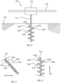
- the detachable connector 48 may include one or more bolts. After the detachable connector 48 is disconnected, and as shown in FIG.
- the superstructure 44 may be pivoted on the pivot point 46 such that the beams 14 swing upward, away from the ground.
- FIG. 2 also shows that the coulter 40 has been removed, but it may also be pivoted or adjusted upward to prevent it from contacting the ground.
- the apparatus 10 may then travel along the ground without disturbing the ground with the beams 14. In particular, this configuration is useful for transport of the apparatus 10 to the field where it will be used, such as along a public roadway or from a storage location to a field.
- the apparatus 10 may include one or more weights 50 to help keep the apparatus 10 and the beams 14 at a constant position with respect to the surface of the ground.
- the weights 50 may also be used to adjust the center of gravity of the apparatus 10.
- FIG. 3 illustrates an apparatus 110 for measuring a soil condition.
- the apparatus 110 is shown in front view, and includes a frame 112 carried by a toolbar 116 of a vehicle (not pictured).
- Beams 114 (indicated 114a, 114b, and 114c, with others unlabeled for simplicity) are attached to the frame 112.
- Load cells 122 (indicated 122a, 122b, and 122c, with others unlabeled for simplicity) are configured to detect forces applied to the beams 114.
- the beams 114 are shown extending below the surface of the ground 118, such that when the apparatus 110 moves along the surface of the ground 118, the beams 114 are deflected based on the resistance of the ground 118.
- the beams 114 that extend deeper into the ground typically experience greater deflection than beams 114 that do not extend as deep (e.g., 114a, 114b).
- Spacing S between the beams 114 may be selected such that each beam 114 does not disturb the neighboring beam(s) 114 when the beams 114 are dragged through the ground 118. That is, the ground 118 disturbed by one beam 114 may not significantly affect the ground 118 adjacent beams 114.
- the spacing S may be at least about 1 cm, at least about 2 cm, at least about 5 cm, or even at least about 10 cm.
- FIG. 4 illustrates another embodiment of an apparatus 210 for measuring a soil condition.
- the apparatus 210 is shown in front view, and includes a frame 212 carried by a toolbar 116 of a vehicle (not pictured).
- the frame 212 includes a shank 214, which carries beams 220 (indicated 220a, 220b, and 220c, with others unlabeled for simplicity).
- the beams 220 are mounted on opposing sides of the shank 214.
- Load cells 222 (indicated 222a, 222b, and 222c, with others unlabeled for simplicity) are configured to detect forces applied to the beams 220.
- the beams 220 are shown below the surface of the ground 118, such that when the apparatus 210 moves along the surface of the ground 118, the beams 220 are deflected based on the resistance of the ground 118.
- the beams 220 that are located deeper into the ground e.g., 220c
- typically experience greater deflection than beams 220 that are not as deep e.g., 220a, 220b).
- FIG. 5 is a side view of the portion of the apparatus 210 of FIG. 4 that is below ground.
- the shank 214 may be a diagonal member, angled forward such that the lowest beams 220 lead the higher beams 220 as the apparatus 210 moves in the direction of travel T.
- FIG. 6 is a top view of the portion of the apparatus 210 of FIG. 4 that is below ground. As shown, the beams 220 may each be angled forward such that the portions of the beams 220 farthest from shank 214 lead portions of the beams 220 closest to the shank 214 as the apparatus 210 moves in the direction of travel T .
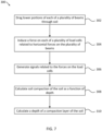
- FIG. 7 is a simplified flow chart illustrating an example method 300 of measuring a property of soil using the apparatus 10, 110, or 210 shown in FIGS. 1-6 and described above. Some operations shown in FIG. 7 are optional, and a person having ordinary skill in the art could select the order of operations to fit operational needs. The operations shown in FIG. 7 may be performed at substantially the same time, and may be performed continuously while operating the apparatus 10, 110, or 210.
- the flow chart in FIG. 7 is not intended to be limiting.
- the method 300 depicted includes, as shown in element 302, dragging lower portions of each of a plurality of beams through soil.
- the beams are carried by a frame and arranged such that a lower extent of the beams differs from one another.
- the dragging may be performed by towing the frame over the soil with a vehicle.
- the dragging may include dragging the beams in a common plane parallel to a direction of travel of the beams.
- the method 300 also includes, as shown in element 304, inducing a force on each of a plurality of load cells related to a horizontal force on the lower portions of the plurality of beams.
- Each load cell is coupled to the frame and a portion of a beam of the plurality.
- the method may include generating signals with the load cells.
- the signals are related to the forces on the load cells.
- the method may include calculating soil compaction of the soil as a function of depth.
- the method may include calculating a force required to move an implement through soil of a certain depth, and the data may be a part of the load profile 92 shown in FIG. 8 .
- the method may include calculating a depth of a compaction layer of the soil.
- the rise 94 in the load profile 92 shown in FIG. 8 may indicate the depth of the compaction layer.
- the apparatuses 10, 110, 210 disclosed herein may be used in conjunction with planting a field.
- data may be collected to map the soil conditions of a field before or during a planting operation.
- the soil conditions may be measured in real time by an apparatus 10, 110, 210 carried by a vehicle that also carries a planting apparatus.
- the planting apparatus e.g., planting depth, downforce, seed population, etc.
- the planting apparatus may be adjusted based on information from the apparatus 10, 110, 210.
- the overall yield of the field may be increased because the planting parameters of each portion of the field may be tailored to the soil conditions at that location.
Landscapes
- Life Sciences & Earth Sciences (AREA)
- Engineering & Computer Science (AREA)
- Chemical & Material Sciences (AREA)
- Health & Medical Sciences (AREA)
- Analytical Chemistry (AREA)
- General Life Sciences & Earth Sciences (AREA)
- Soil Sciences (AREA)
- General Health & Medical Sciences (AREA)
- Medicinal Chemistry (AREA)
- Pathology (AREA)
- Immunology (AREA)
- General Physics & Mathematics (AREA)
- Biochemistry (AREA)
- Environmental & Geological Engineering (AREA)
- Geology (AREA)
- Remote Sensing (AREA)
- Physics & Mathematics (AREA)
- Food Science & Technology (AREA)
- Civil Engineering (AREA)
- Paleontology (AREA)
- Environmental Sciences (AREA)
- Mining & Mineral Resources (AREA)
- Mechanical Engineering (AREA)
- Structural Engineering (AREA)
- General Engineering & Computer Science (AREA)
- Investigating Strength Of Materials By Application Of Mechanical Stress (AREA)
- Investigation Of Foundation Soil And Reinforcement Of Foundation Soil By Compacting Or Drainage (AREA)
- Investigating Or Analyzing Materials By The Use Of Electric Means (AREA)
Claims (12)
- Vorrichtung (210) zum Messen eines Bodenzustands, wobei die Vorrichtung (210) aufweist:eine Mehrzahl von länglichen Stäben (220a-c), welche auf gegenüberliegenden Seiten eines Schafts (214) befestigt und auf unterschiedlichen Höhen entlang des Schafts (214) angeordnet sind; undeine Mehrzahl von Kraftaufnehmern (222a-c), wobei jeder Kraftaufnehmer (222a-c) der Mehrzahl von Kraftaufnehmern (222a-c) so mit dem Schaft (214) und mit einem Stab (220a-c) der Mehrzahl von Stäben (220a-c) gekoppelt ist, dass eine horizontale Kraft auf den Stab (220a-c) den Kraftaufnehmer (222a-c) veranlasst, ein zu einer Kraft auf den Stab (220a-c) korrespondierendes Signal zu generieren.
- Vorrichtung (210) nach Anspruch 1, weiterhin mit einem in Kommunikation mit den Kraftaufnehmern (222a-c) stehenden Empfänger (28), wobei der Empfänger (28) eingerichtet ist, die Signale von den Kraftaufnehmern (222a-c) zu empfangen.
- Vorrichtung (210) nach Anspruch 2, weiterhin mit einem Prozessor (30), welcher eingerichtet ist, eine Eigenschaft eines Bodens, durch welchen zumindest Teile der Stäbe (220a-c) hindurchtreten, zu berechnen.
- Vorrichtung (210) nach Anspruch 3, weiterhin mit einem Sender (34), welcher eingerichtet ist, die Eigenschaft des Bodens zu übermitteln.
- Vorrichtung (210) nach einem der Ansprüche 1 bis 4, wobei der Schaft (214) von einem Rahmen (212) getragen wird, und die Vorrichtung weiterhin eine an den Rahmen (212) gekoppelte Anhängerkupplung aufweist.
- Vorrichtung (210) nach einem der Ansprüche 1 bis 4, wobei die Mehrzahl von Stäben (220a-c) eingerichtet ist, vollständig unter einer Bodenoberfläche (118) angeordnet zu werden, wenn die Vorrichtung (210) entlang der Bodenoberfläche (118) bewegt wird.
- Verfahren (300) zum Messen einer Eigenschaft eines Bodens, wobei das Verfahren aufweist:Ziehen (302) zumindest eines Teils eines Schafts (214) durch einen Boden, wobei der Schaft (214) eine Mehrzahl von länglichen Stäben (220a-c) trägt, welche auf gegenüberliegenden Seiten des Schafts (214) montiert und auf unterschiedlichen Höhen angeordnet sind;Einleiten (304) einer Kraft auf jeden einer Mehrzahl von Kraftaufnehmern (222a-c) bezogen auf horizontale Kräfte auf die Mehrzahl von Stäben (220a-c) wobei jeder Kraftaufnehmer (222a-c) mit dem Schaft (214) und einem Stab (220a-c) der Mehrzahl gekoppelt ist; undGenerieren (306) von Signalen mit den Kraftaufnehmern (222a-c), wobei sich die Signale auf die Kräfte auf die Kraftaufnehmer (220a-c) beziehen.
- Verfahren (300) nach Anspruch 7, weiterhin mit Ermitteln (308) einer Bodenverdichtung des Bodens als Funktion der Tiefe basierend zumindest teilweise auf den Signalen.
- Verfahren (300) nach Anspruch 8, weiterhin mit Ermitteln (310) einer Tiefe einer Verdichtungsschicht des Bodens basierend zumindest teilweise auf den Signalen.
- Verfahren (300) nach einem der Ansprüche 7 bis 9, wobei das Ziehen zumindest eines Teils eines Schafts (214) durch einen Boden ein Schleppen des Schafts (214) durch den Boden mit einem Fahrzeug aufweist.
- Verfahren (300) nach einem der Ansprüche 7 bis 9, wobei das Ziehen zumindest eines Teils eines Schafts (214) durch einen Boden ein Orientieren des Schafts (214) aufweist, derart dass ein erster Stab (220a) der Mehrzahl einem zweiten Stab (220b) der Mehrzahl in einer Fortbewegungsrichtung (T) des Schafts (214) vorläuft, wobei der erste Stab (220a) tiefer in dem Boden ist als der zweite Stab (220b).
- Verfahren (300) nach einem der Ansprüche 7 bis 9, wobei das Ziehen zumindest eines Teils eines Schafts (214) durch einen Boden ein Orientieren des Schafts (214) aufweist, derart dass ein dem Schaft (214) ferner Teil eines Stabs (220a-c) der Mehrzahl einem anderen mit dem Schaft (214) verbundenen Teil des Stabs (220a-c) in einer Fortbewegungsrichtung (T) des Schafts (214) vorläuft.
Applications Claiming Priority (2)
| Application Number | Priority Date | Filing Date | Title |
|---|---|---|---|
| US201962832621P | 2019-04-11 | 2019-04-11 | |
| PCT/IB2020/051243 WO2020208431A1 (en) | 2019-04-11 | 2020-02-14 | Apparatus and methods for measuring soil conditions |
Publications (2)
| Publication Number | Publication Date |
|---|---|
| EP3953705A1 EP3953705A1 (de) | 2022-02-16 |
| EP3953705B1 true EP3953705B1 (de) | 2024-04-24 |
Family
ID=69740433
Family Applications (1)
| Application Number | Title | Priority Date | Filing Date |
|---|---|---|---|
| EP20708639.8A Active EP3953705B1 (de) | 2019-04-11 | 2020-02-14 | Vorrichtung und verfahren zur messung von bodenbedingungen |
Country Status (3)
| Country | Link |
|---|---|
| US (1) | US20220159900A1 (de) |
| EP (1) | EP3953705B1 (de) |
| WO (1) | WO2020208431A1 (de) |
Family Cites Families (8)
| Publication number | Priority date | Publication date | Assignee | Title |
|---|---|---|---|---|
| US6041582A (en) * | 1998-02-20 | 2000-03-28 | Case Corporation | System for recording soil conditions |
| WO2001004627A1 (en) * | 1999-07-08 | 2001-01-18 | Omron Corporation | Soil measuring instrument, soil measurement assisting device and method, recorded medium on which program is recorded, recorded medium on which data is recorded, application amount controller, application amount determining device, method for them, and farm working determination assisting system |
| US6497153B1 (en) * | 2000-09-28 | 2002-12-24 | Bechtel Bwxt Idaho, Llc | Measuring spatial variability in soil characteristics |
| US20030016029A1 (en) * | 2001-07-18 | 2003-01-23 | Schuler Ronald T. | Soil moisture measuring system for a mobile agricultural device |
| US6834550B2 (en) | 2001-09-10 | 2004-12-28 | The Regents Of The University Of California | Soil profile force measurement using an instrumented tine |
| US7299686B2 (en) * | 2004-03-02 | 2007-11-27 | The Texas A&M University System | System and method for testing the compaction of soil |
| CA3047779A1 (en) * | 2016-12-19 | 2018-06-28 | The Climate Corporation | Systems, methods and apparatus for soil and seed monitoring |
| EP4175451B1 (de) * | 2020-07-02 | 2024-10-23 | Precision Planting LLC | Geräte und methoden zur messung der bodenbeschaffenheit |
-
2020
- 2020-02-14 WO PCT/IB2020/051243 patent/WO2020208431A1/en not_active Ceased
- 2020-02-14 EP EP20708639.8A patent/EP3953705B1/de active Active
- 2020-02-14 US US17/594,019 patent/US20220159900A1/en not_active Abandoned
Also Published As
| Publication number | Publication date |
|---|---|
| US20220159900A1 (en) | 2022-05-26 |
| WO2020208431A1 (en) | 2020-10-15 |
| EP3953705A1 (de) | 2022-02-16 |
Similar Documents
| Publication | Publication Date | Title |
|---|---|---|
| CN114651564B (zh) | 种子沟槽闭合传感器 | |
| RU2720278C2 (ru) | Устройство, система и способ мониторинга критериев почвы во время операций обработки почвы и управление почвообрабатывающими рабочими органами | |
| US8561472B2 (en) | Load sensing pin | |
| US20220272888A1 (en) | Agricultural Implements and Methods of Planting | |
| US9433142B2 (en) | Tool control system for agricultural seeders | |
| US20240188472A1 (en) | Agricultural implements having row unit position sensors and at least one adjustable wheel, and related control systems and methods | |
| US20120125244A1 (en) | Mapping soil hardness | |
| US20230354735A1 (en) | Agricultural implements having sensors to detect plugging of row units, and related control systems and methods | |
| EP3953705B1 (de) | Vorrichtung und verfahren zur messung von bodenbedingungen | |
| EP4175451B1 (de) | Geräte und methoden zur messung der bodenbeschaffenheit | |
| US20220091089A1 (en) | Apparatus and methods for measuring soil conditions | |
| EP3395143B1 (de) | Landwirtschaftlicher schaft mit geschütztem bodensensor | |
| CN212436258U (zh) | 一种振动深松施肥机 | |
| WO2020208430A1 (en) | Tillage implements and methods of identifying a compaction layer | |
| US20230270039A1 (en) | Agricultural implements having row unit position sensors and actuators configured to rotate toolbars, and related control systems and methods | |
| Badua et al. | Quantifying real-time opening disk load during planting operations to assess compaction and potential for planter control | |
| Varga et al. | Measurement of soil resistance by using a horizontal penetrometer working with the two-argument comparative method. | |
| US20220386519A1 (en) | Automated tillage disk gang angle adjustment | |
| Keen et al. | Improvements to the tractive efficiency of agricultural tractors carrying out cultivations | |
| Dua et al. | Optimization of GWL margin to enhance planter performance | |
| CN118129962A (zh) | 一种土壤机械阻力动态检测装置及深松机 | |
| Kumar et al. | Sensors for Soil Hard Pan Determination-A Review |
Legal Events
| Date | Code | Title | Description |
|---|---|---|---|
| STAA | Information on the status of an ep patent application or granted ep patent |
Free format text: STATUS: UNKNOWN |
|
| STAA | Information on the status of an ep patent application or granted ep patent |
Free format text: STATUS: THE INTERNATIONAL PUBLICATION HAS BEEN MADE |
|
| PUAI | Public reference made under article 153(3) epc to a published international application that has entered the european phase |
Free format text: ORIGINAL CODE: 0009012 |
|
| STAA | Information on the status of an ep patent application or granted ep patent |
Free format text: STATUS: REQUEST FOR EXAMINATION WAS MADE |
|
| 17P | Request for examination filed |
Effective date: 20211111 |
|
| AK | Designated contracting states |
Kind code of ref document: A1 Designated state(s): AL AT BE BG CH CY CZ DE DK EE ES FI FR GB GR HR HU IE IS IT LI LT LU LV MC MK MT NL NO PL PT RO RS SE SI SK SM TR |
|
| DAV | Request for validation of the european patent (deleted) | ||
| DAX | Request for extension of the european patent (deleted) | ||
| P01 | Opt-out of the competence of the unified patent court (upc) registered |
Effective date: 20230518 |
|
| GRAP | Despatch of communication of intention to grant a patent |
Free format text: ORIGINAL CODE: EPIDOSNIGR1 |
|
| STAA | Information on the status of an ep patent application or granted ep patent |
Free format text: STATUS: GRANT OF PATENT IS INTENDED |
|
| GRAS | Grant fee paid |
Free format text: ORIGINAL CODE: EPIDOSNIGR3 |
|
| INTG | Intention to grant announced |
Effective date: 20240222 |
|
| GRAA | (expected) grant |
Free format text: ORIGINAL CODE: 0009210 |
|
| STAA | Information on the status of an ep patent application or granted ep patent |
Free format text: STATUS: THE PATENT HAS BEEN GRANTED |
|
| AK | Designated contracting states |
Kind code of ref document: B1 Designated state(s): AL AT BE BG CH CY CZ DE DK EE ES FI FR GB GR HR HU IE IS IT LI LT LU LV MC MK MT NL NO PL PT RO RS SE SI SK SM TR |
|
| REG | Reference to a national code |
Ref country code: GB Ref legal event code: FG4D |
|
| REG | Reference to a national code |
Ref country code: CH Ref legal event code: EP |
|
| REG | Reference to a national code |
Ref country code: DE Ref legal event code: R096 Ref document number: 602020029523 Country of ref document: DE |
|
| REG | Reference to a national code |
Ref country code: IE Ref legal event code: FG4D |
|
| REG | Reference to a national code |
Ref country code: LT Ref legal event code: MG9D |
|
| REG | Reference to a national code |
Ref country code: NL Ref legal event code: MP Effective date: 20240424 |
|
| REG | Reference to a national code |
Ref country code: AT Ref legal event code: MK05 Ref document number: 1680111 Country of ref document: AT Kind code of ref document: T Effective date: 20240424 |
|
| PG25 | Lapsed in a contracting state [announced via postgrant information from national office to epo] |
Ref country code: NL Free format text: LAPSE BECAUSE OF FAILURE TO SUBMIT A TRANSLATION OF THE DESCRIPTION OR TO PAY THE FEE WITHIN THE PRESCRIBED TIME-LIMIT Effective date: 20240424 |
|
| PG25 | Lapsed in a contracting state [announced via postgrant information from national office to epo] |
Ref country code: NL Free format text: LAPSE BECAUSE OF FAILURE TO SUBMIT A TRANSLATION OF THE DESCRIPTION OR TO PAY THE FEE WITHIN THE PRESCRIBED TIME-LIMIT Effective date: 20240424 |
|
| PG25 | Lapsed in a contracting state [announced via postgrant information from national office to epo] |
Ref country code: IS Free format text: LAPSE BECAUSE OF FAILURE TO SUBMIT A TRANSLATION OF THE DESCRIPTION OR TO PAY THE FEE WITHIN THE PRESCRIBED TIME-LIMIT Effective date: 20240824 |
|
| PG25 | Lapsed in a contracting state [announced via postgrant information from national office to epo] |
Ref country code: BG Free format text: LAPSE BECAUSE OF FAILURE TO SUBMIT A TRANSLATION OF THE DESCRIPTION OR TO PAY THE FEE WITHIN THE PRESCRIBED TIME-LIMIT Effective date: 20240424 |
|
| PG25 | Lapsed in a contracting state [announced via postgrant information from national office to epo] |
Ref country code: HR Free format text: LAPSE BECAUSE OF FAILURE TO SUBMIT A TRANSLATION OF THE DESCRIPTION OR TO PAY THE FEE WITHIN THE PRESCRIBED TIME-LIMIT Effective date: 20240424 Ref country code: FI Free format text: LAPSE BECAUSE OF FAILURE TO SUBMIT A TRANSLATION OF THE DESCRIPTION OR TO PAY THE FEE WITHIN THE PRESCRIBED TIME-LIMIT Effective date: 20240424 |
|
| PG25 | Lapsed in a contracting state [announced via postgrant information from national office to epo] |
Ref country code: GR Free format text: LAPSE BECAUSE OF FAILURE TO SUBMIT A TRANSLATION OF THE DESCRIPTION OR TO PAY THE FEE WITHIN THE PRESCRIBED TIME-LIMIT Effective date: 20240725 |
|
| PG25 | Lapsed in a contracting state [announced via postgrant information from national office to epo] |
Ref country code: PT Free format text: LAPSE BECAUSE OF FAILURE TO SUBMIT A TRANSLATION OF THE DESCRIPTION OR TO PAY THE FEE WITHIN THE PRESCRIBED TIME-LIMIT Effective date: 20240826 |
|
| PG25 | Lapsed in a contracting state [announced via postgrant information from national office to epo] |
Ref country code: ES Free format text: LAPSE BECAUSE OF FAILURE TO SUBMIT A TRANSLATION OF THE DESCRIPTION OR TO PAY THE FEE WITHIN THE PRESCRIBED TIME-LIMIT Effective date: 20240424 |
|
| PG25 | Lapsed in a contracting state [announced via postgrant information from national office to epo] |
Ref country code: AT Free format text: LAPSE BECAUSE OF FAILURE TO SUBMIT A TRANSLATION OF THE DESCRIPTION OR TO PAY THE FEE WITHIN THE PRESCRIBED TIME-LIMIT Effective date: 20240424 |
|
| PG25 | Lapsed in a contracting state [announced via postgrant information from national office to epo] |
Ref country code: PL Free format text: LAPSE BECAUSE OF FAILURE TO SUBMIT A TRANSLATION OF THE DESCRIPTION OR TO PAY THE FEE WITHIN THE PRESCRIBED TIME-LIMIT Effective date: 20240424 |
|
| PG25 | Lapsed in a contracting state [announced via postgrant information from national office to epo] |
Ref country code: LV Free format text: LAPSE BECAUSE OF FAILURE TO SUBMIT A TRANSLATION OF THE DESCRIPTION OR TO PAY THE FEE WITHIN THE PRESCRIBED TIME-LIMIT Effective date: 20240424 |
|
| PG25 | Lapsed in a contracting state [announced via postgrant information from national office to epo] |
Ref country code: PT Free format text: LAPSE BECAUSE OF FAILURE TO SUBMIT A TRANSLATION OF THE DESCRIPTION OR TO PAY THE FEE WITHIN THE PRESCRIBED TIME-LIMIT Effective date: 20240826 Ref country code: PL Free format text: LAPSE BECAUSE OF FAILURE TO SUBMIT A TRANSLATION OF THE DESCRIPTION OR TO PAY THE FEE WITHIN THE PRESCRIBED TIME-LIMIT Effective date: 20240424 Ref country code: NO Free format text: LAPSE BECAUSE OF FAILURE TO SUBMIT A TRANSLATION OF THE DESCRIPTION OR TO PAY THE FEE WITHIN THE PRESCRIBED TIME-LIMIT Effective date: 20240724 Ref country code: LV Free format text: LAPSE BECAUSE OF FAILURE TO SUBMIT A TRANSLATION OF THE DESCRIPTION OR TO PAY THE FEE WITHIN THE PRESCRIBED TIME-LIMIT Effective date: 20240424 Ref country code: IS Free format text: LAPSE BECAUSE OF FAILURE TO SUBMIT A TRANSLATION OF THE DESCRIPTION OR TO PAY THE FEE WITHIN THE PRESCRIBED TIME-LIMIT Effective date: 20240824 Ref country code: HR Free format text: LAPSE BECAUSE OF FAILURE TO SUBMIT A TRANSLATION OF THE DESCRIPTION OR TO PAY THE FEE WITHIN THE PRESCRIBED TIME-LIMIT Effective date: 20240424 Ref country code: GR Free format text: LAPSE BECAUSE OF FAILURE TO SUBMIT A TRANSLATION OF THE DESCRIPTION OR TO PAY THE FEE WITHIN THE PRESCRIBED TIME-LIMIT Effective date: 20240725 Ref country code: FI Free format text: LAPSE BECAUSE OF FAILURE TO SUBMIT A TRANSLATION OF THE DESCRIPTION OR TO PAY THE FEE WITHIN THE PRESCRIBED TIME-LIMIT Effective date: 20240424 Ref country code: ES Free format text: LAPSE BECAUSE OF FAILURE TO SUBMIT A TRANSLATION OF THE DESCRIPTION OR TO PAY THE FEE WITHIN THE PRESCRIBED TIME-LIMIT Effective date: 20240424 Ref country code: BG Free format text: LAPSE BECAUSE OF FAILURE TO SUBMIT A TRANSLATION OF THE DESCRIPTION OR TO PAY THE FEE WITHIN THE PRESCRIBED TIME-LIMIT Effective date: 20240424 Ref country code: AT Free format text: LAPSE BECAUSE OF FAILURE TO SUBMIT A TRANSLATION OF THE DESCRIPTION OR TO PAY THE FEE WITHIN THE PRESCRIBED TIME-LIMIT Effective date: 20240424 Ref country code: RS Free format text: LAPSE BECAUSE OF FAILURE TO SUBMIT A TRANSLATION OF THE DESCRIPTION OR TO PAY THE FEE WITHIN THE PRESCRIBED TIME-LIMIT Effective date: 20240724 |
|
| PG25 | Lapsed in a contracting state [announced via postgrant information from national office to epo] |
Ref country code: DK Free format text: LAPSE BECAUSE OF FAILURE TO SUBMIT A TRANSLATION OF THE DESCRIPTION OR TO PAY THE FEE WITHIN THE PRESCRIBED TIME-LIMIT Effective date: 20240424 |
|
| PG25 | Lapsed in a contracting state [announced via postgrant information from national office to epo] |
Ref country code: EE Free format text: LAPSE BECAUSE OF FAILURE TO SUBMIT A TRANSLATION OF THE DESCRIPTION OR TO PAY THE FEE WITHIN THE PRESCRIBED TIME-LIMIT Effective date: 20240424 |
|
| PG25 | Lapsed in a contracting state [announced via postgrant information from national office to epo] |
Ref country code: CZ Free format text: LAPSE BECAUSE OF FAILURE TO SUBMIT A TRANSLATION OF THE DESCRIPTION OR TO PAY THE FEE WITHIN THE PRESCRIBED TIME-LIMIT Effective date: 20240424 |
|
| PG25 | Lapsed in a contracting state [announced via postgrant information from national office to epo] |
Ref country code: RO Free format text: LAPSE BECAUSE OF FAILURE TO SUBMIT A TRANSLATION OF THE DESCRIPTION OR TO PAY THE FEE WITHIN THE PRESCRIBED TIME-LIMIT Effective date: 20240424 Ref country code: SK Free format text: LAPSE BECAUSE OF FAILURE TO SUBMIT A TRANSLATION OF THE DESCRIPTION OR TO PAY THE FEE WITHIN THE PRESCRIBED TIME-LIMIT Effective date: 20240424 |
|
| REG | Reference to a national code |
Ref country code: DE Ref legal event code: R097 Ref document number: 602020029523 Country of ref document: DE |
|
| PG25 | Lapsed in a contracting state [announced via postgrant information from national office to epo] |
Ref country code: SM Free format text: LAPSE BECAUSE OF FAILURE TO SUBMIT A TRANSLATION OF THE DESCRIPTION OR TO PAY THE FEE WITHIN THE PRESCRIBED TIME-LIMIT Effective date: 20240424 |
|
| PG25 | Lapsed in a contracting state [announced via postgrant information from national office to epo] |
Ref country code: SM Free format text: LAPSE BECAUSE OF FAILURE TO SUBMIT A TRANSLATION OF THE DESCRIPTION OR TO PAY THE FEE WITHIN THE PRESCRIBED TIME-LIMIT Effective date: 20240424 Ref country code: SK Free format text: LAPSE BECAUSE OF FAILURE TO SUBMIT A TRANSLATION OF THE DESCRIPTION OR TO PAY THE FEE WITHIN THE PRESCRIBED TIME-LIMIT Effective date: 20240424 Ref country code: RO Free format text: LAPSE BECAUSE OF FAILURE TO SUBMIT A TRANSLATION OF THE DESCRIPTION OR TO PAY THE FEE WITHIN THE PRESCRIBED TIME-LIMIT Effective date: 20240424 Ref country code: EE Free format text: LAPSE BECAUSE OF FAILURE TO SUBMIT A TRANSLATION OF THE DESCRIPTION OR TO PAY THE FEE WITHIN THE PRESCRIBED TIME-LIMIT Effective date: 20240424 Ref country code: DK Free format text: LAPSE BECAUSE OF FAILURE TO SUBMIT A TRANSLATION OF THE DESCRIPTION OR TO PAY THE FEE WITHIN THE PRESCRIBED TIME-LIMIT Effective date: 20240424 Ref country code: CZ Free format text: LAPSE BECAUSE OF FAILURE TO SUBMIT A TRANSLATION OF THE DESCRIPTION OR TO PAY THE FEE WITHIN THE PRESCRIBED TIME-LIMIT Effective date: 20240424 |
|
| PLBE | No opposition filed within time limit |
Free format text: ORIGINAL CODE: 0009261 |
|
| STAA | Information on the status of an ep patent application or granted ep patent |
Free format text: STATUS: NO OPPOSITION FILED WITHIN TIME LIMIT |
|
| 26N | No opposition filed |
Effective date: 20250127 |
|
| PG25 | Lapsed in a contracting state [announced via postgrant information from national office to epo] |
Ref country code: SI Free format text: LAPSE BECAUSE OF FAILURE TO SUBMIT A TRANSLATION OF THE DESCRIPTION OR TO PAY THE FEE WITHIN THE PRESCRIBED TIME-LIMIT Effective date: 20240424 |
|
| REG | Reference to a national code |
Ref country code: DE Ref legal event code: R119 Ref document number: 602020029523 Country of ref document: DE |
|
| PG25 | Lapsed in a contracting state [announced via postgrant information from national office to epo] |
Ref country code: SE Free format text: LAPSE BECAUSE OF FAILURE TO SUBMIT A TRANSLATION OF THE DESCRIPTION OR TO PAY THE FEE WITHIN THE PRESCRIBED TIME-LIMIT Effective date: 20240424 |
|
| PG25 | Lapsed in a contracting state [announced via postgrant information from national office to epo] |
Ref country code: MC Free format text: LAPSE BECAUSE OF FAILURE TO SUBMIT A TRANSLATION OF THE DESCRIPTION OR TO PAY THE FEE WITHIN THE PRESCRIBED TIME-LIMIT Effective date: 20240424 |
|
| REG | Reference to a national code |
Ref country code: CH Ref legal event code: PL |
|
| PG25 | Lapsed in a contracting state [announced via postgrant information from national office to epo] |
Ref country code: LU Free format text: LAPSE BECAUSE OF NON-PAYMENT OF DUE FEES Effective date: 20250214 |
|
| PG25 | Lapsed in a contracting state [announced via postgrant information from national office to epo] |
Ref country code: CH Free format text: LAPSE BECAUSE OF NON-PAYMENT OF DUE FEES Effective date: 20250228 |
|
| GBPC | Gb: european patent ceased through non-payment of renewal fee |
Effective date: 20250214 |
|
| REG | Reference to a national code |
Ref country code: BE Ref legal event code: MM Effective date: 20250228 |
|
| PG25 | Lapsed in a contracting state [announced via postgrant information from national office to epo] |
Ref country code: DE Free format text: LAPSE BECAUSE OF NON-PAYMENT OF DUE FEES Effective date: 20250902 |
|
| PG25 | Lapsed in a contracting state [announced via postgrant information from national office to epo] |
Ref country code: GB Free format text: LAPSE BECAUSE OF NON-PAYMENT OF DUE FEES Effective date: 20250214 |
|
| PG25 | Lapsed in a contracting state [announced via postgrant information from national office to epo] |
Ref country code: FR Free format text: LAPSE BECAUSE OF NON-PAYMENT OF DUE FEES Effective date: 20250228 |
|
| PG25 | Lapsed in a contracting state [announced via postgrant information from national office to epo] |
Ref country code: BE Free format text: LAPSE BECAUSE OF NON-PAYMENT OF DUE FEES Effective date: 20250228 |
|
| PG25 | Lapsed in a contracting state [announced via postgrant information from national office to epo] |
Ref country code: IE Free format text: LAPSE BECAUSE OF NON-PAYMENT OF DUE FEES Effective date: 20250214 |
|
| PG25 | Lapsed in a contracting state [announced via postgrant information from national office to epo] |
Ref country code: IT Free format text: LAPSE BECAUSE OF FAILURE TO SUBMIT A TRANSLATION OF THE DESCRIPTION OR TO PAY THE FEE WITHIN THE PRESCRIBED TIME-LIMIT Effective date: 20240424 |