EP2803739B1 - Flash-behälter und betriebsverfahren dafür - Google Patents
Flash-behälter und betriebsverfahren dafür Download PDFInfo
- Publication number
- EP2803739B1 EP2803739B1 EP12865429.0A EP12865429A EP2803739B1 EP 2803739 B1 EP2803739 B1 EP 2803739B1 EP 12865429 A EP12865429 A EP 12865429A EP 2803739 B1 EP2803739 B1 EP 2803739B1
- Authority
- EP
- European Patent Office
- Prior art keywords
- liquid level
- slurry
- flash vessel
- outlet pipe
- level sensor
- Prior art date
- Legal status (The legal status is an assumption and is not a legal conclusion. Google has not performed a legal analysis and makes no representation as to the accuracy of the status listed.)
- Active
Links
Images


Classifications
-
- C—CHEMISTRY; METALLURGY
- C22—METALLURGY; FERROUS OR NON-FERROUS ALLOYS; TREATMENT OF ALLOYS OR NON-FERROUS METALS
- C22B—PRODUCTION AND REFINING OF METALS; PRETREATMENT OF RAW MATERIALS
- C22B23/00—Obtaining nickel or cobalt
- C22B23/04—Obtaining nickel or cobalt by wet processes
- C22B23/0407—Leaching processes
- C22B23/0415—Leaching processes with acids or salt solutions except ammonium salts solutions
- C22B23/043—Sulfurated acids or salts thereof
-
- B—PERFORMING OPERATIONS; TRANSPORTING
- B01—PHYSICAL OR CHEMICAL PROCESSES OR APPARATUS IN GENERAL
- B01J—CHEMICAL OR PHYSICAL PROCESSES, e.g. CATALYSIS OR COLLOID CHEMISTRY; THEIR RELEVANT APPARATUS
- B01J3/00—Processes of utilising sub-atmospheric or super-atmospheric pressure to effect chemical or physical change of matter; Apparatus therefor
- B01J3/04—Pressure vessels, e.g. autoclaves
-
- B—PERFORMING OPERATIONS; TRANSPORTING
- B01—PHYSICAL OR CHEMICAL PROCESSES OR APPARATUS IN GENERAL
- B01J—CHEMICAL OR PHYSICAL PROCESSES, e.g. CATALYSIS OR COLLOID CHEMISTRY; THEIR RELEVANT APPARATUS
- B01J4/00—Feed or outlet devices; Feed or outlet control devices
- B01J4/008—Feed or outlet control devices
-
- C—CHEMISTRY; METALLURGY
- C22—METALLURGY; FERROUS OR NON-FERROUS ALLOYS; TREATMENT OF ALLOYS OR NON-FERROUS METALS
- C22B—PRODUCTION AND REFINING OF METALS; PRETREATMENT OF RAW MATERIALS
- C22B3/00—Extraction of metal compounds from ores or concentrates by wet processes
- C22B3/02—Apparatus therefor
-
- C—CHEMISTRY; METALLURGY
- C22—METALLURGY; FERROUS OR NON-FERROUS ALLOYS; TREATMENT OF ALLOYS OR NON-FERROUS METALS
- C22B—PRODUCTION AND REFINING OF METALS; PRETREATMENT OF RAW MATERIALS
- C22B3/00—Extraction of metal compounds from ores or concentrates by wet processes
- C22B3/04—Extraction of metal compounds from ores or concentrates by wet processes by leaching
- C22B3/06—Extraction of metal compounds from ores or concentrates by wet processes by leaching in inorganic acid solutions, e.g. with acids generated in situ; in inorganic salt solutions other than ammonium salt solutions
- C22B3/08—Sulfuric acid, other sulfurated acids or salts thereof
-
- B—PERFORMING OPERATIONS; TRANSPORTING
- B01—PHYSICAL OR CHEMICAL PROCESSES OR APPARATUS IN GENERAL
- B01J—CHEMICAL OR PHYSICAL PROCESSES, e.g. CATALYSIS OR COLLOID CHEMISTRY; THEIR RELEVANT APPARATUS
- B01J2219/00—Chemical, physical or physico-chemical processes in general; Their relevant apparatus
- B01J2219/00049—Controlling or regulating processes
- B01J2219/00182—Controlling or regulating processes controlling the level of reactants in the reactor vessel
-
- Y—GENERAL TAGGING OF NEW TECHNOLOGICAL DEVELOPMENTS; GENERAL TAGGING OF CROSS-SECTIONAL TECHNOLOGIES SPANNING OVER SEVERAL SECTIONS OF THE IPC; TECHNICAL SUBJECTS COVERED BY FORMER USPC CROSS-REFERENCE ART COLLECTIONS [XRACs] AND DIGESTS
- Y02—TECHNOLOGIES OR APPLICATIONS FOR MITIGATION OR ADAPTATION AGAINST CLIMATE CHANGE
- Y02P—CLIMATE CHANGE MITIGATION TECHNOLOGIES IN THE PRODUCTION OR PROCESSING OF GOODS
- Y02P10/00—Technologies related to metal processing
- Y02P10/20—Recycling
Definitions
- the present invention relates to a flash vessel and a method for operating same, and more particularly to a flash vessel and a method for operating same vessel used in a high pressure acid leach step which includes leaching material slurry under high temperature and pressure conditions by using an autoclave (high-pressure reaction vessel), and then reducing the temperature and pressure of the slurry after leach to the ordinary temperature and ordinary pressure by using a flash vessel (temperature and pressure reduction vessel).
- a flash vessel temperature and pressure reduction vessel
- high temperature pressurized acid leach which uses sulfuric acid has been attracting attention as a hydrometallurgical process of nickel oxide ore (for example, see Patent Literature 1).
- This method does not include dry steps such as deoxidizing and drying step, but includes consistent wet steps unlike a conventional typical dry smelting method for nickel oxide ore and accordingly, the high pressure acid leach is advantageous in view of energy-saving and cost-performance.
- iron corresponding to a main impurity is fixed as leach residue in the form of hematite (Fe 2 O 3 ) by controlling the oxidization-reduction potential and temperature of the leachate within the pressurized leach reaction vessel in the leach step.
- hematite Fe 2 O 3
- high pressure acid leach using an autoclave is adopted as a hydrometallurgical process of nickel oxide ore.
- the liquid level within the flash vessel is generally measured by a sensor directly attached to the flash vessel.
- the flash vessel 100 includes a bottomed cylindrical body 101.
- a slurry inlet port 103 and a vapor outlet port 105 are provided at a ceiling portion 102 which closes the upper part of the body 101.
- a slurry outlet port 104 is provided at the body 101.
- a slurry inlet pipe 113 through which slurry after leach and reduction to predetermined temperature and predetermined pressure (hereinafter simply abbreviated as slurry in some cases) is introduced into the interior of the flash vessel 100, is coupled with the slurry inlet port 103.
- a slurry outlet pipe 114 through which the slurry having entered the interior of the flash vessel 100 is discharged, is coupled with the slurry outlet port 104.
- a vapor outlet pipe 115 through which vapor generated within the flash vessel 100 by introduction of the slurry is recovered, is coupled with the vapor outlet port 105.
- a slurry outlet valve 116 is provided on the slurry outlet pipe 114 coupled with the slurry outlet port 104.
- slurry after leach and reduction to predetermined temperature and predetermined pressure (hereinafter abbreviated as slurry in some cases) is introduced through the slurry inlet port 103, the slurry having entered the interior of the flash vessel 100 is discharged through the slurry outlet port 104 and the vapor generated by introduction of the slurry is discharged through the vapor outlet port 105.
- the liquid level within the flash vessel 100 is maintained at an appropriate level based on measurement results of the liquid level within the flash vessel obtained by using liquid level sensors 120A and 120B.
- the slurry remaining within the flash vessel 100 is discharged by opening the slurry outlet valve 116 when the liquid level sensor 120A disposed at the maximum liquid level detects a rising liquid level.
- the discharge of the slurry from the flash vessel 100 is stopped by closing the slurry outlet valve 116. Consequently, the slurry liquid level within the flash vessel 100 is adjusted within the range between the maximum liquid level and the minimum liquid level.
- the discharge amount of the slurry remaining within the flash vessel 100 is raised by increasing the opening of the slurry outlet valve 116 when the liquid level exceeds the control liquid level, and reduced by decreasing the opening of the slurry outlet valve 116 when the liquid level becomes lower than the control liquid level.
- the leach reaction in the high pressure acid leach step is controlled based on control factors (pH and oxidation-reduction potential) of leach reaction produced by using a leaching agent, as well as based on temperature.
- control factors pH and oxidation-reduction potential
- the leaching reaction is controlled by oxidation-reduction potential in the leachate.
- the pressure within the autoclave is not directly controlled, and thus is not necessarily stable or constant during the leaching operation. Accordingly, the pressure is variable in accordance with the injective amount of chlorine gas controlled by the oxidation-reduction potential.
- the pressure within the autoclave is generally produced by saturated vapor pressure dependent on temperature.
- high pressure acid leach using an autoclave is adopted as a hydrometallurgical process of nickel oxide ore so as to recover valuable metal such as nickel and cobalt.
- this high pressure acid leach for example, ore slurry containing ore having a predetermined slurry concentration and a size of 2 mm or smaller is initially prepared by using pulverizing equipment and screening equipment and the ore slurry is supplied to the high pressure acid leach step.
- the temperature and pressure of the ore slurry are increased step by step by using a preheater (temperature and pressure raising equipment), and the resultant slurry is supplied to an autoclave.
- nickel and cobalt contained in the ore, and a part of impurity elements such as iron, aluminum, and zinc are leached by using sulfuric acid to obtain slurry containing these materials after leach.
- the slurry after leach is supplied from the autoclave to a flash vessel which reduces the temperature and pressure of the slurry after leach to the ordinary temperature and pressure, where the temperature and pressure of the slurry are reduced step by step. Thereafter, the slurry undergoes a preliminary neutralization step for neutralizing free sulfuric acid within the leachate, a solid-liquid separation step implemented by thickeners with a multiple-stage types, and other steps to be separated into leach residues and leachate.
- the adoption of the flash vessel in the high pressure acid leach step eliminates the gap between the operation condition of the autoclave used in the high pressure acid leach step and that in the subsequent step. More specifically, the leach condition for the autoclave is generally adjusted to a temperature approximately in the range from 200°C to 300°C for obtaining high leach rate of nickel and cobalt. On the other hand, in the subsequent preliminary neutralization step or solid-liquid separation step, the operation is generally performed under the atmospheric pressure for safety and economic reasons. Accordingly, the flash vessel reduces the temperature and pressure while recovering pressurized vapor step by step from the high-temperature and high-pressure slurry after leach.
- the transfer of slurry after leach between the respective flash vessels is conducted by a method using the height differences of the places where the respective flash vessels are installed, and the pressure differences between the respective stages, rather than by adopting a mechanical transfer method such as a pump.
- This type of transfer is adopted in consideration of the durability and cost of the transfer equipment which transfers slurry after leach containing sulfuric acid.
- the first stage flash vessel is located at a position corresponding to the height approximately in the range from 25 m to 35 m above the autoclave.
- the pressurized vapor recovered step by step from the high-temperature and high-pressure slurry after leach is supplied from the flash vessels in the respective stages to preheaters having approximately the same temperature and pressure and the piping in this process is also provided with extremely expensive pipes made of material and structure sufficiently resistant to the pressurized vapor having high temperature and high pressure similarly to above.
- the estimated factor causing these problems is the insufficient control of the liquid level. More specifically, the slurry liquid level does not become flat in the condition where steam is generated by introduction of the high-temperature and high pressure slurry after leach into the flash vessel and rather than that, it is assumed that the liquid level is heavily variable by the steam generated from the depth of the slurry, in which condition the control of the liquid level is insufficient.
- the flash vessel which reduces the temperature and pressure of the slurry obtained by leaching material slurry under high temperature and pressure conditions using the autoclave, is a large-sized flash vessel handling strong acid slurry. Accordingly, an inspection hole is difficult to be formed for technical reasons and visual inspection is substantially impossible.
- the liquid level control by the slurry outlet valve 116 does not work, and the actual liquid level becomes lower than the slurry outlet pipe 114 and the vapor within the flash vessel 100 is discharged to the flash vessel disposed in the stage subsequent to the slurry outlet pipe 114 together with the discharged slurry, whereby the slurry flow speed within the outlet pipe temporarily increases and as a result, the slurry outlet pipe 114 and the valve may be broken, or the amount of the introduced vapor from the flash tank in the subsequent stage into the recovery vapor pipe temporarily increases. In this condition, corrosion and abrasion of the recovery vapor pipe may develop with increase in the carried sulfuric acid and increase in the flow speed.
- Patent Literature 2 discloses a technology relating to organic sludge slurry condensing method which constantly locates the liquid level of condensed liquid to an upper position than an outlet port based on detection of the liquid level within a flash vessel.
- this method is difficult to be adopted as it is due to the extremely different conditions in the point that the method is targeted to organic sludge slurry, and that the vapor pressure is only 2.5 atm, for example.
- Patent Literature 3 discloses a technology which controls refrigerant charge into a refrigerant vapor compression system by using at least one sensor provided to detect the level of liquid refrigerant within a flash vessel included in the system.
- this technology uses a sensor of float type or ultrasonic type, for example, which is applicable only when the liquid level is flat. Accordingly, this technology is difficult to adopt to the foregoing problems.
- US-patent 5,052,426 discloses a system for pressure letdown of abrasive slurries.
- a flash vessel and a method for operating same used in a high pressure acid leach step which includes leaching material slurry under high temperature and pressure conditions by using an autoclave, and reducing the temperature and pressure of the slurry after leach to the ordinary temperature and ordinary pressure by using the flash vessel.
- This flash vessel appropriately controls the opening and closing of a valve based on highly accurate information on the slurry liquid level obtained by raising the accuracy of the liquid level measurement of the flash vessel and accordingly, the flash vessel and the method for operating same can reduce troubles of a vapor outlet pipe, a slurry outlet pipe, and a slurry outlet valve.
- the present inventors devoted themselves to the studies of liquid level measurement of a flash vessel used in a high pressure acid leach step which includes leaching material slurry under high temperature and pressure conditions by using an autoclave, and reducing the temperature and pressure of the slurry after leach to the ordinary temperature and ordinary pressure by using the flash vessel. After repeated studies, the inventors have found that the liquid level measurement accuracy improves when the liquid level is measured in a hydrostatic tower provided on the flash vessel, and finally completed the invention described below.
- a flash vessel whose liquid level rises and drops considerably used in a high pressure acid leach step which includes leaching nickel oxide ore slurry under high temperature and pressure conditions by using an autoclave, and reducing the temperature and pressure of the slurry after leach to the ordinary temperature and ordinary pressure by using the flash vessel, includes: a hydrostatic tower which is provided with at least one maximum liquid level sensor and at least one minimum liquid level sensor and whose lower part is coupled with an arbitrary position on a slurry outlet pipe between the connection position of the slurry outlet pipe and the flash vessel and the position of a slurry outlet valve, and whose upper part is coupled with an arbitrary position on a vapor outlet pipe; wherein the at least one maximum liquid level sensor is provided at a position at the same level as a maximum liquid level not causing inflow of the slurry into the vapor outlet pipe due to considerable rise and drop of the slurry liquid level within the liquid phase space of the flash vessel to detect a rising liquid level within the hydrostatic tower; and wherein the
- a diameter A of the hydrostatic tower may lie in the range 1/100 ⁇ B ⁇ A ⁇ 1/5 ⁇ B in comparison with a diameter B of the flash vessel.
- a method for operating a flash vessel whose liquid level rises and drops considerably according to the invention used in a high pressure acid leach step which includes leaching nickel oxide ore slurry under high temperature and pressure conditions by using an autoclave, and reducing the temperature and pressure of the slurry after leach to the ordinary temperature and ordinary pressure by using the flash vessel includes: detecting a liquid level within a hydrostatic tower whose lower part is coupled with an arbitrary position on a slurry outlet pipe between the connection position of the slurry outlet pipe and the flash vessel and the position of a slurry outlet valve, and whose upper part is coupled with an arbitrary position on a vapor outlet pipe by using at least one maximum liquid level sensor provided at a position at the same level as a maximum liquid level not causing inflow of the slurry into the vapor outlet pipe due to considerable rise and drop of the slurry liquid level within the liquid phase space of the flash vessel and at least one minimum liquid level sensor provided at a position at the same level as a minimum liquid level not causing inflow of vapor
- the opening and closing of a valve is appropriately controlled based on highly accurate information on the slurry liquid level obtained by raising the accuracy of the liquid level measurement of the flash vessel. Accordingly, the flash vessel and the method for operating same can reduce troubles of a vapor outlet pipe, a slurry outlet pipe, and a slurry outlet valve and these technical achievements are extremely advantageous.
- the invention is applicable to a flash vessel 10 having the structure illustrated in Fig. 1 , for example.
- the flash vessel 10 is a flash vessel used in a high pressure acid leach step which leaches material slurry under high temperature and pressure conditions using an autoclave, and reduces the temperature and pressure of the slurry after leach to the ordinary temperature and pressure.
- the flash vessel 10 includes a bottomed cylindrical body 1 and a slurry inlet port 3 and a vapor outlet port 5 are formed in a ceiling portion 2 closing the upper part of the body 1.
- a slurry outlet port 4 is provided at the body 1.
- a slurry outlet valve 16 is provided on the slurry outlet pipe 14 coupled with the slurry outlet port 4.
- slurry after leach and reduction to the predetermined temperature and predetermined pressure is introduced through the slurry inlet port 3 and slurry having entered the interior of the flash vessel 10 is discharged through the slurry outlet port 4 and vapor generated by introduction of slurry is discharged through the vapor outlet port 5.
- the material slurry in this context is nickel oxide ore slurry.
- slurry obtained by leaching nickel oxide ore slurry using sulfuric acid is introduced into the flash vessel 10, and the temperature and pressure of the introduced slurry are reduced to the ordinary temperature and ordinary pressure.
- the flash vessel 10 includes a hydrostatic tower 20 whose lower part communicates with a liquid phase space within the flash vessel 10, and whose upper part communicates with a gas phase space within the flash vessel 10.
- the lower part of the hydrostatic tower 20 is coupled with an arbitrary position on the slurry outlet pipe 14 between the connection position of the slurry outlet pipe 14 and the flash vessel 10 and the position of the slurry outlet valve 16.
- the upper part of the hydrostatic tower 20 is coupled with an arbitrary position on the vapor outlet pipe 15.
- the diameter of the hydrostatic tower 20 is not particularly limited, however, it is preferable that a diameter A of the hydrostatic tower 20 lies in the range 1/100 ⁇ B ⁇ A ⁇ 1/5 ⁇ B in comparison with a diameter B of the flash vessel 10.
- a diameter A of the hydrostatic tower 20 lies in the range 1/100 ⁇ B ⁇ A ⁇ 1/5 ⁇ B in comparison with a diameter B of the flash vessel 10.
- the hydrostatic tower 20 is provided with at least one maximum liquid level sensor 21A, and at least one minimum liquid level sensor 21B:
- the maximum liquid level sensor 21A is disposed at the same level as a predetermined maximum liquid level in the liquid phase space, and detects a rising liquid level within the hydrostatic tower 20.
- the minimum liquid level sensor 21B is disposed at the same level as a predetermined minimum liquid level in the liquid phase space, and detects a dropping liquid level within the hydrostatic tower 20.
- the liquid level within the flash vessel 10 is maintained at an appropriate level by controlling the valve opening of the slurry outlet valve 16 in accordance with the liquid level measurement results obtained by the liquid level sensors 21A and 21B provided on the hydrostatic tower 20.
- the flash vessel 10 as a flash vessel used in a high pressure acid leach step which leaches material slurry under high temperature and pressure conditions using an autoclave, and reduces the temperature and pressure of the slurry after leach to the ordinary temperature and ordinary pressure, is operated in the following manners.
- the lower part of the hydrostatic tower 20 communicates with the liquid phase space within the flash vessel 10, while the upper part of the hydrostatic tower 20 communicates with the gas phase space within the flash vessel 10.
- the liquid level within the hydrostatic tower 20 is detected by at least the one maximum liquid level sensor 21A disposed at the same level as a predetermined maximum liquid level in the liquid phase space, and the one minimum liquid level sensor 21B disposed at the same level as a predetermined minimum liquid level in the liquid phase space.
- the slurry outlet valve 16 disposed on the slurry outlet pipe 14 derived from the flash vessel 10 is opened when the maximum liquid level sensor 21A detects a rising liquid level within the hydrostatic tower 20, and closed when the minimum liquid level sensor 21B detects a dropping liquid level within the hydrostatic tower 20.
- the slurry liquid level within the flash vessel 10 can be adjusted to a level within an appropriate range.
- vapor is difficult to flow toward the slurry outlet pipe 14 side, and therefore the problem of damage to the slurry outlet valve 16 decreases.
- the material slurry introduced into the flash vessel 10 is not particularly limited.
- the material slurry includes materials containing various types of metal compounds from which desired metal is leached by high pressure acid leach, such as metal, sulfide, oxide, and ore slurry composed of nickel oxide ore is preferable, for example.
- the high pressure acid leach step is not particularly limited and the step includes preheaters employed in typical high pressure acid leach for increasing the temperature and pressure of ore slurry step by step, as well as the autoclave and the flash vessels.
- the autoclave is not particularly limited and the autoclave includes a vertical-type or horizontal-type pressurizing vessel heated externally or heated by blown-in pressurized steam.
- the flash vessel 10 is not particularly limited.
- the flash vessel 10 is constituted by a multistage-type flash vessel.
- the preheaters are not particularly limited.
- the preheaters are constituted by multistage-type counterflow direct-heating type heat exchangers.
- steam is used as the heating medium.
- the steam used herein may be steam generated by using a boiler or by other typical methods. It is preferable, however, that the steam generated in the flash vessel at the time of step-by-step reduction of the temperature and pressure of the slurry after leach and discharge from the autoclave is recovered and circulated to be used as the heating medium.
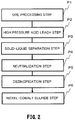
- the high pressure acid leach for nickel oxide ore includes an ore processing step P1, a high pressure acid leach step P2, a solid-liquid separation step P3, a neutralization step P4, a dezincification step P5, and a nickel-cobalt sulfurizing step P6.
- the ore slurry transferred from the ore processing step is preheated by preheaters.
- the preheated ore slurry is leached in an autoclave under high temperature and pressure conditions by using sulfuric acid while high pressure air and high pressure steam are being blown into the autoclave. Then, the temperature and pressure of the high-temperature and high-pressure slurry after leach are reduced by using the flash vessel 10.
- the slurry after leach is separated into solid and liquid to obtain leachate and leach residue.
- nickel-cobalt mixture sulfide is extracted from the leachate by sulfide sedimentation.
- the nickel oxide ore is so-called laterite chiefly constituted by limonite and saprolite.
- the laterite generally has a nickel content in the range from 0.5 % to 2.0 % by mass, containing nickel as hydroxide or magnesium silicate ore.
- the laterite has an iron content in the range from 20 % to 50 % by mass, containing iron chiefly in the form of trivalent hydroxide (goethite, FeOOH), and partially divalent iron in magnesium silicate ore.
- the slurry concentration of the ore slurry manufactured in the ore processing step P1 is greatly dependent on the properties of nickel oxide ore to be processed, and is therefore not particularly limited, however, it is preferable that the slurry concentration of the slurry after leach is high and this concentration is generally adjusted in the range from 20 % to 50 % by mass. That is, when the slurry concentration of the slurry after leach is lower than 20 % by mass, large equipment is required to obtain the same residence time for each of the respective steps including the leach step and in addition, the additive amount of acid increases for adjustment of the residue acid concentration. Moreover, the nickel concentration of the obtained leachate becomes lower, with a result that the final recovery rate may decrease.
- Examples of practical equipment used in the high pressure acid leach step P2 include three preheaters, an autoclave, and three flash vessels, for example.
- the flash vessel 10 contains a cylindrical vessel having a size approximately in the range from 4 m to 6 m in diameter and approximately in the range from 10 m to 12 m in height, and vertically installed.
- the slurry introduced into the first stage flash vessel has a temperature in the range from 200°C to 270°C, for example, and a pressure in the range from 1.8 MPaG to 5.8 MPaG, for example.
- the flash vessel 10 used in the high pressure acid leach step P2 is constructed as follows, for example.
- the lower part of the hydrostatic tower 20 having a diameter of 250 mm was coupled with the slurry outlet pipe 14 at the intermediate position between the connection position of the slurry outlet pipe 14 and the flash vessel 10 and the position of the slurry outlet valve 16 (position shifted from the connection position by approximately 50 cm).
- the upper part of the hydrostatic tower 20 having a diameter of 250 mm was coupled with the vapor outlet pipe 15 at the position shifted from the connection position of the vapor outlet pipe 15 and the flash vessel 10 by approximately 50 cm.
- the one liquid level sensor 21A was provided on the hydrostatic tower 20 at the position shifted from the bottom of the flash vessel 10 by approximately 6.5 m (the same level as predetermined maximum liquid level).
- the one liquid level sensor 21B was provided at the position shifted from the bottom of the flash vessel 10 by approximately 4.5 m (the same level as predetermined minimum liquid level).
- the length of 250 mm as the diameter of the hydrostatic tower 20 corresponds to 1/20 of the diameter of the main body which is approximately 5 m.
- the flash vessel 10 thus constructed is operated in the high pressure acid leach step P2 in the following manners.
- Slurry is successively introduced into the flash vessel 10.
- the maximum liquid level sensor 21A detects a rising liquid level at the time of closure of the slurry outlet valve 16
- a signal for opening the valve is transmitted to the slurry outlet valve 16.
- the slurry outlet valve 16 is opened to transfer the slurry within the flash vessel 10 to the subsequent step.
- the minimum liquid level sensor 21B detects a dropping liquid level
- a signal for closing the outlet valve is transmitted to the slurry outlet valve 16. Based on this signal, the slurry outlet valve 16 is closed, whereby the slurry liquid level within the flash vessel 10 starts rising again. The work can continue by repeating these procedures.
- Table 1 shows results of analysis for ore slurry of nickel oxide ore used in the example and comparison example.
- Slurry produced by leaching ore slurry shown in Table 1 and adjusting the slurry after leach to approximately 245°C and approximately 4 MPaG at the exit of the autoclave was introduced into a first stage flash vessel.
- the slurry introduced into the first flash vessel was sequentially transferred to the second stage and third stage flash vessels to decrease the pressure of the slurry after leach to the ordinary pressure. This work was executed for six months.
- Example 1 The same work as that of Example 1 was executed not using the practical equipment example for the high pressure acid leach step discussed herein, but using conventional equipment not provided with a hydrostatic tower.
Landscapes
- Chemical & Material Sciences (AREA)
- Engineering & Computer Science (AREA)
- Organic Chemistry (AREA)
- Metallurgy (AREA)
- Mechanical Engineering (AREA)
- Materials Engineering (AREA)
- Manufacturing & Machinery (AREA)
- Geology (AREA)
- Life Sciences & Earth Sciences (AREA)
- Geochemistry & Mineralogy (AREA)
- General Life Sciences & Earth Sciences (AREA)
- Environmental & Geological Engineering (AREA)
- Chemical Kinetics & Catalysis (AREA)
- Inorganic Chemistry (AREA)
- Manufacture And Refinement Of Metals (AREA)
- Feeding, Discharge, Calcimining, Fusing, And Gas-Generation Devices (AREA)
- Extraction Or Liquid Replacement (AREA)
Claims (3)
- Entspannungsverdampfungsgefäß (10), dessen Flüssigkeitspegel bei Verwendung in einem Hochdruck-Säureauslaugungsschritt, welcher das Auslaugen von Nickeloxiderz-Aufschlämmung unter Hochtemperatur- und -druckbedingungen durch Verwendung eines Autoklavs und Herabsetzen der Temperatur und des Drucks der Aufschlämmung nach Auslaugung auf Standardtemperatur und Standarddruck durch Verwendung des Entspannungsverdampfungsgefäßes (10) einschließt, beachtlich steigt und sinkt, umfassend:einen hydrostatischen Turm (20), welcher mit mindestens einem Maximalflüssigkeitspegelsensor (21A) und mindestens einem Minimalflüssigkeitspegelsensor (21B) ausgestattet ist und dessen unterer Bereich mit einer beliebigen Stelle an einem Aufschlämmungsauslassrohr (14) zwischen der Anschlussstelle des Aufschlämmungsauslassrohres (14) und des Entspannungsverdampfungsgefäßes (10) und der Stelle eines Aufschlämmungsauslassventils (16) gekoppelt ist und dessen oberer Bereich mit einer beliebigen Stelle an einem Dampfauslassrohr (15) gekoppelt ist,wobei der mindestens eine Maximalflüssigkeitspegelsensor (21A) an einer Stelle auf dem gleichen Pegel wie ein Maximalflüssigkeitspegel, der nicht Eindringen der Aufschlämmung in das Dampfauslassrohr (15) aufgrund beachtlichen Steigens und Sinkens des Aufschlämmungsflüssigkeitspegels in den Flüssigphasenraum des Entspannungsverdampfungsgefäßes (10) verursacht, zur Detektion eines steigenden Flüssigkeitspegels in dem hydrostatischen Turm (20) angeordnet ist, undwobei der mindestens eine Minimalflüssigkeitspegelsensor (21B) an einer Stelle auf dem gleichen Pegel wie ein Minimalflüssigkeitspegel, der nicht Eindringen von Dampf in das Aufschlämmungsauslassrohr (14) aufgrund beachtlichen Steigens und Sinkens des Aufschlämmungsflüssigkeitspegels in den Flüssigphasenraum verursacht, zur Detektion eines sinkenden Flüssigkeitspegels in dem hydrostatischen Turm (20) angeordnet ist; undein durch Aufschlämmungsauslassventil (16) kontrolliertes Öffnen und Schließen, entsprechend dem Detektionsergebnis durch den Maximalflüssigkeitspegelsensor (21A) und den Minimalflüssigkeitspegelsensor (21B), welche den Flüssigkeitspegel des hydrostatischen Turms (20) detektieren, geöffnet, wenn der Maximalflüssigkeitspegelsensor (21A) einen steigenden Flüssigkeitspegel in dem hydrostatischen Turm (20) detektiert, und geschlossen, wenn der Minimalflüssigkeitspegelsensor (21B) einen sinkenden Flüssigkeitspegel in dem hydrostatischen Turm (20) detektiert.
- Entspannungsverdampfungsgefäß (10) nach Anspruch 1, wobei ein Durchmesser A des hydrostatischen Turms (20) in dem Bereich 1/100 × B ≤ A ≤ 1/5 × B, im Vergleich zu einem Durchmesser B des Entspannungsverdampfungsgefäßes (10), liegt.
- Verfahren zum Betreiben eines Entspannungsverdampfungsgefäßes (10), dessen Flüssigkeitspegel bei Verwendung in einem Hochdruck-Säureauslaugungsschritt, welcher das Auslaugen von Nickeloxiderz-Aufschlämmung unter Hochtemperatur- und -druckbedingungen durch Verwendung eines Autoklavs und Herabsetzen der Temperatur und des Drucks der Aufschlämmung nach Auslaugung auf Standardtemperatur und Standarddruck durch Verwendung des Entspannungsverdampfungsgefäßes (10) einschließt, beachtlich steigt und sinkt, wobei das Verfahren umfasst:Detektieren eines Flüssigkeitspegels innerhalb eines hydrostatischen Turms (20), dessen unterer Bereich mit einer beliebigen Stelle an einem Aufschlämmungsauslassrohr (14) zwischen der Anschlussstelle des Aufschlämmungsauslassrohres (14) und des Entspannungsverdampfungsgefäßes (10) und der Stelle eines Aufschlämmungsauslassventils (16) gekoppelt ist und dessen oberer Bereich mit einer beliebigen Stelle an einem Dampfauslassrohr (15) gekoppelt ist;durch Verwendung mindestens eines Maximalflüssigkeitspegelsensors (21A), angeordnet an einer Stelle auf dem gleichen Pegel wie ein Maximalflüssigkeitspegel, der nicht Eindringen der Aufschlämmung in das Dampfauslassrohr (15) aufgrund beachtlichen Steigens und Sinkens des Aufschlämmungsflüssigkeitspegels in den Flüssigphasenraum des Entspannungsverdampfungsgefäßes (10) verursacht, und mindestens eines Minimalflüssigkeitspegelsensors (21B), angeordnet an einer Stelle auf dem gleichen Pegel wie ein Minimalflüssigkeitspegel, der nicht Eindringen von Dampf in das Aufschlämmungsauslassrohr (14) aufgrund beachtlichen Steigens und Sinkens des Aufschlämmungsflüssigkeitspegels in den Flüssigphasenraum verursacht; undÖffnen eines Aufschlämmungsauslassventils (16), angeordnet an einem von dem Entspannungsverdampfungsgefäß (10) abgehenden Aufschlämmungsauslassrohr (14), wenn der Maximalflüssigkeitspegelsensor (21A) einen steigenden Flüssigkeitspegel in dem hydrostatischen Turm (20) detektiert, und Schließen des Aufschlämmungsauslassventils (16), wenn der Minimalflüssigkeitspegelsensor (21B) einen sinkenden Flüssigkeitspegel in dem hydrostatischen Turm (20) detektiert.
Applications Claiming Priority (2)
| Application Number | Priority Date | Filing Date | Title |
|---|---|---|---|
| JP2012005442 | 2012-01-13 | ||
| PCT/JP2012/083948 WO2013105454A1 (ja) | 2012-01-13 | 2012-12-27 | フラッシュベッセル及びその運転方法 |
Publications (3)
| Publication Number | Publication Date |
|---|---|
| EP2803739A1 EP2803739A1 (de) | 2014-11-19 |
| EP2803739A4 EP2803739A4 (de) | 2015-07-15 |
| EP2803739B1 true EP2803739B1 (de) | 2018-03-14 |
Family
ID=48781410
Family Applications (1)
| Application Number | Title | Priority Date | Filing Date |
|---|---|---|---|
| EP12865429.0A Active EP2803739B1 (de) | 2012-01-13 | 2012-12-27 | Flash-behälter und betriebsverfahren dafür |
Country Status (8)
| Country | Link |
|---|---|
| US (1) | US9464341B2 (de) |
| EP (1) | EP2803739B1 (de) |
| JP (2) | JP5582265B2 (de) |
| CN (1) | CN104039993B (de) |
| AU (1) | AU2012365089B2 (de) |
| CA (1) | CA2861034C (de) |
| PH (1) | PH12014501592B1 (de) |
| WO (1) | WO2013105454A1 (de) |
Families Citing this family (15)
| Publication number | Priority date | Publication date | Assignee | Title |
|---|---|---|---|---|
| CN104039993B (zh) * | 2012-01-13 | 2016-03-30 | 住友金属矿山株式会社 | 闪蒸器及其运转方法 |
| JP5871033B2 (ja) * | 2014-07-08 | 2016-03-01 | 住友金属鉱山株式会社 | 蒸気配管破損検知装置 |
| JP6459879B2 (ja) * | 2015-09-28 | 2019-01-30 | 住友金属鉱山株式会社 | ニッケル粉の製造方法、反応設備の運転方法 |
| JP6226027B1 (ja) * | 2016-05-19 | 2017-11-08 | 住友金属鉱山株式会社 | アングル弁 |
| JP6245314B2 (ja) | 2016-05-30 | 2017-12-13 | 住友金属鉱山株式会社 | ニッケル粉の製造方法 |
| JP6819087B2 (ja) | 2016-06-21 | 2021-01-27 | 住友金属鉱山株式会社 | ニッケル粉の製造方法、ニッケル粉の製造装置 |
| FR3062799B1 (fr) | 2017-02-10 | 2021-09-10 | Starklab | Dispositif pour la production et le traitement de flux gazeux a travers un volume de liquide regule automatiquement |
| JP6972607B2 (ja) * | 2017-03-27 | 2021-11-24 | 住友金属鉱山株式会社 | フラットバルブの制御方法、フラットバルブの制御システム |
| JP6919408B2 (ja) * | 2017-08-17 | 2021-08-18 | 住友金属鉱山株式会社 | 反応容器 |
| JP6720946B2 (ja) * | 2017-09-21 | 2020-07-08 | 住友金属鉱山株式会社 | アングル弁 |
| JP7110578B2 (ja) * | 2017-10-23 | 2022-08-02 | 住友金属鉱山株式会社 | オートクレーブの制御システム、及び制御方法 |
| US20200368638A1 (en) * | 2019-05-21 | 2020-11-26 | Michael J. O'Brien | System and method for separating components from high pressure co2 |
| CN112029993B (zh) * | 2020-08-31 | 2024-03-19 | 中国恩菲工程技术有限公司 | 浸出液冷却设备和冷却工艺 |
| JP7571477B2 (ja) * | 2020-11-06 | 2024-10-23 | 住友金属鉱山株式会社 | フラッシュベッセル内からの残留物の排出方法 |
| WO2025020175A1 (zh) * | 2023-07-27 | 2025-01-30 | Esg新能源材料有限公司 | 一种红土镍矿高压浸出停留时间优化系统 |
Family Cites Families (18)
| Publication number | Priority date | Publication date | Assignee | Title |
|---|---|---|---|---|
| JPS5836294B2 (ja) * | 1979-01-17 | 1983-08-08 | 横河電機株式会社 | 微小流量計測方法 |
| US4551198A (en) * | 1982-03-30 | 1985-11-05 | Kamyr, Inc. | Method of flashing black liquor |
| JPS5959605U (ja) * | 1982-10-13 | 1984-04-18 | 三菱重工業株式会社 | フラツシユタンク |
| US4466253A (en) * | 1982-12-23 | 1984-08-21 | General Electric Company | Flow control at flash tank of open cycle vapor compression heat pumps |
| US5052426A (en) * | 1991-01-16 | 1991-10-01 | The United States Of America As Represented By The United States Department Of Energy | System for pressure letdown of abrasive slurries |
| JPH0714770A (ja) * | 1993-06-25 | 1995-01-17 | Hitachi Ltd | 液体ソース供給装置 |
| JPH09218072A (ja) * | 1996-02-13 | 1997-08-19 | Yamaha Motor Co Ltd | 液面レベルセンサー |
| JP3646131B2 (ja) | 1996-05-31 | 2005-05-11 | 東京都 | 有機性汚泥の処理方法 |
| CA2387633C (en) * | 2002-05-24 | 2011-04-26 | Cominco Engineering Services Ltd. | Chloride assisted hydrometallurgical extraction of metals |
| CN100417629C (zh) * | 2006-04-13 | 2008-09-10 | 四川大学 | 磷铵料浆反应-浓缩蒸发器布置方法 |
| DK1974171T3 (da) * | 2006-09-29 | 2014-08-18 | Carrier Corp | Kompressionssystem til kølemiddeldamp med flash tank modtager |
| JP5287010B2 (ja) * | 2008-07-31 | 2013-09-11 | 住友金属鉱山株式会社 | ニッケル酸化鉱石の湿式製錬方法 |
| JP5332418B2 (ja) * | 2008-09-04 | 2013-11-06 | 住友金属鉱山株式会社 | オートクレーブの圧力調整方法 |
| JP5605991B2 (ja) * | 2009-01-14 | 2014-10-15 | 株式会社神戸製鋼所 | 蒸気発生装置 |
| US20110174113A1 (en) * | 2010-01-18 | 2011-07-21 | Gme Resources Ltd. | Acid Recovery |
| JP2011194313A (ja) * | 2010-03-18 | 2011-10-06 | Sumco Corp | バブリング装置及び方法 |
| CN104039993B (zh) * | 2012-01-13 | 2016-03-30 | 住友金属矿山株式会社 | 闪蒸器及其运转方法 |
| WO2013105453A1 (ja) * | 2012-01-13 | 2013-07-18 | 住友金属鉱山株式会社 | フラッシュベッセルの運転方法 |
-
2012
- 2012-12-27 CN CN201280066905.8A patent/CN104039993B/zh active Active
- 2012-12-27 AU AU2012365089A patent/AU2012365089B2/en active Active
- 2012-12-27 EP EP12865429.0A patent/EP2803739B1/de active Active
- 2012-12-27 WO PCT/JP2012/083948 patent/WO2013105454A1/ja not_active Ceased
- 2012-12-27 US US14/370,882 patent/US9464341B2/en active Active
- 2012-12-27 CA CA2861034A patent/CA2861034C/en active Active
- 2012-12-27 JP JP2013553250A patent/JP5582265B2/ja active Active
-
2014
- 2014-07-03 JP JP2014138082A patent/JP5768918B2/ja active Active
- 2014-07-10 PH PH12014501592A patent/PH12014501592B1/en unknown
Non-Patent Citations (1)
| Title |
|---|
| None * |
Also Published As
| Publication number | Publication date |
|---|---|
| CN104039993A (zh) | 2014-09-10 |
| AU2012365089A1 (en) | 2014-07-31 |
| CA2861034A1 (en) | 2013-07-18 |
| PH12014501592A1 (en) | 2014-10-08 |
| EP2803739A1 (de) | 2014-11-19 |
| AU2012365089B2 (en) | 2016-11-03 |
| CN104039993B (zh) | 2016-03-30 |
| EP2803739A4 (de) | 2015-07-15 |
| JP5582265B2 (ja) | 2014-09-03 |
| CA2861034C (en) | 2019-08-13 |
| PH12014501592B1 (en) | 2014-10-08 |
| US20150145183A1 (en) | 2015-05-28 |
| WO2013105454A1 (ja) | 2013-07-18 |
| AU2012365089A2 (en) | 2014-08-28 |
| JP5768918B2 (ja) | 2015-08-26 |
| US9464341B2 (en) | 2016-10-11 |
| JPWO2013105454A1 (ja) | 2015-05-11 |
| JP2014240524A (ja) | 2014-12-25 |
Similar Documents
| Publication | Publication Date | Title |
|---|---|---|
| EP2803739B1 (de) | Flash-behälter und betriebsverfahren dafür | |
| JP5332418B2 (ja) | オートクレーブの圧力調整方法 | |
| CN104039992B (zh) | 闪蒸器的运转方法 | |
| JP5287010B2 (ja) | ニッケル酸化鉱石の湿式製錬方法 | |
| JP6135609B2 (ja) | オートクレーブへのガス吹込み方法 | |
| JP7047502B2 (ja) | 高圧蒸気の供給遮断システム及びこれを備えた高圧酸浸出設備 | |
| JP7226181B2 (ja) | 硫化水素ガスの除害設備 | |
| JP7571477B2 (ja) | フラッシュベッセル内からの残留物の排出方法 | |
| JP6862970B2 (ja) | 硫化物の製造設備 | |
| JP7230699B2 (ja) | 高温高圧容器の撹拌機の軸封用シール水供給装置 | |
| JP7215373B2 (ja) | 硫化水素ガスの除害設備 |
Legal Events
| Date | Code | Title | Description |
|---|---|---|---|
| PUAI | Public reference made under article 153(3) epc to a published international application that has entered the european phase |
Free format text: ORIGINAL CODE: 0009012 |
|
| 17P | Request for examination filed |
Effective date: 20140717 |
|
| AK | Designated contracting states |
Kind code of ref document: A1 Designated state(s): AL AT BE BG CH CY CZ DE DK EE ES FI FR GB GR HR HU IE IS IT LI LT LU LV MC MK MT NL NO PL PT RO RS SE SI SK SM TR |
|
| DAX | Request for extension of the european patent (deleted) | ||
| RA4 | Supplementary search report drawn up and despatched (corrected) |
Effective date: 20150616 |
|
| RIC1 | Information provided on ipc code assigned before grant |
Ipc: C22B 23/00 20060101AFI20150610BHEP Ipc: B01J 3/02 20060101ALI20150610BHEP Ipc: F17C 13/00 20060101ALI20150610BHEP Ipc: C22B 3/04 20060101ALI20150610BHEP |
|
| 17Q | First examination report despatched |
Effective date: 20170308 |
|
| GRAP | Despatch of communication of intention to grant a patent |
Free format text: ORIGINAL CODE: EPIDOSNIGR1 |
|
| INTG | Intention to grant announced |
Effective date: 20171005 |
|
| GRAS | Grant fee paid |
Free format text: ORIGINAL CODE: EPIDOSNIGR3 |
|
| GRAA | (expected) grant |
Free format text: ORIGINAL CODE: 0009210 |
|
| AK | Designated contracting states |
Kind code of ref document: B1 Designated state(s): AL AT BE BG CH CY CZ DE DK EE ES FI FR GB GR HR HU IE IS IT LI LT LU LV MC MK MT NL NO PL PT RO RS SE SI SK SM TR |
|
| REG | Reference to a national code |
Ref country code: GB Ref legal event code: FG4D |
|
| REG | Reference to a national code |
Ref country code: CH Ref legal event code: EP Ref country code: AT Ref legal event code: REF Ref document number: 978939 Country of ref document: AT Kind code of ref document: T Effective date: 20180315 |
|
| REG | Reference to a national code |
Ref country code: IE Ref legal event code: FG4D |
|
| REG | Reference to a national code |
Ref country code: DE Ref legal event code: R096 Ref document number: 602012044070 Country of ref document: DE |
|
| REG | Reference to a national code |
Ref country code: NL Ref legal event code: MP Effective date: 20180314 |
|
| REG | Reference to a national code |
Ref country code: LT Ref legal event code: MG4D |
|
| PG25 | Lapsed in a contracting state [announced via postgrant information from national office to epo] |
Ref country code: LT Free format text: LAPSE BECAUSE OF FAILURE TO SUBMIT A TRANSLATION OF THE DESCRIPTION OR TO PAY THE FEE WITHIN THE PRESCRIBED TIME-LIMIT Effective date: 20180314 Ref country code: HR Free format text: LAPSE BECAUSE OF FAILURE TO SUBMIT A TRANSLATION OF THE DESCRIPTION OR TO PAY THE FEE WITHIN THE PRESCRIBED TIME-LIMIT Effective date: 20180314 Ref country code: NO Free format text: LAPSE BECAUSE OF FAILURE TO SUBMIT A TRANSLATION OF THE DESCRIPTION OR TO PAY THE FEE WITHIN THE PRESCRIBED TIME-LIMIT Effective date: 20180614 Ref country code: FI Free format text: LAPSE BECAUSE OF FAILURE TO SUBMIT A TRANSLATION OF THE DESCRIPTION OR TO PAY THE FEE WITHIN THE PRESCRIBED TIME-LIMIT Effective date: 20180314 Ref country code: CY Free format text: LAPSE BECAUSE OF FAILURE TO SUBMIT A TRANSLATION OF THE DESCRIPTION OR TO PAY THE FEE WITHIN THE PRESCRIBED TIME-LIMIT Effective date: 20180314 |
|
| REG | Reference to a national code |
Ref country code: AT Ref legal event code: MK05 Ref document number: 978939 Country of ref document: AT Kind code of ref document: T Effective date: 20180314 |
|
| PG25 | Lapsed in a contracting state [announced via postgrant information from national office to epo] |
Ref country code: RS Free format text: LAPSE BECAUSE OF FAILURE TO SUBMIT A TRANSLATION OF THE DESCRIPTION OR TO PAY THE FEE WITHIN THE PRESCRIBED TIME-LIMIT Effective date: 20180314 Ref country code: SE Free format text: LAPSE BECAUSE OF FAILURE TO SUBMIT A TRANSLATION OF THE DESCRIPTION OR TO PAY THE FEE WITHIN THE PRESCRIBED TIME-LIMIT Effective date: 20180314 Ref country code: LV Free format text: LAPSE BECAUSE OF FAILURE TO SUBMIT A TRANSLATION OF THE DESCRIPTION OR TO PAY THE FEE WITHIN THE PRESCRIBED TIME-LIMIT Effective date: 20180314 Ref country code: GR Free format text: LAPSE BECAUSE OF FAILURE TO SUBMIT A TRANSLATION OF THE DESCRIPTION OR TO PAY THE FEE WITHIN THE PRESCRIBED TIME-LIMIT Effective date: 20180615 Ref country code: BG Free format text: LAPSE BECAUSE OF FAILURE TO SUBMIT A TRANSLATION OF THE DESCRIPTION OR TO PAY THE FEE WITHIN THE PRESCRIBED TIME-LIMIT Effective date: 20180614 |
|
| PG25 | Lapsed in a contracting state [announced via postgrant information from national office to epo] |
Ref country code: AL Free format text: LAPSE BECAUSE OF FAILURE TO SUBMIT A TRANSLATION OF THE DESCRIPTION OR TO PAY THE FEE WITHIN THE PRESCRIBED TIME-LIMIT Effective date: 20180314 Ref country code: IT Free format text: LAPSE BECAUSE OF FAILURE TO SUBMIT A TRANSLATION OF THE DESCRIPTION OR TO PAY THE FEE WITHIN THE PRESCRIBED TIME-LIMIT Effective date: 20180314 Ref country code: EE Free format text: LAPSE BECAUSE OF FAILURE TO SUBMIT A TRANSLATION OF THE DESCRIPTION OR TO PAY THE FEE WITHIN THE PRESCRIBED TIME-LIMIT Effective date: 20180314 Ref country code: PL Free format text: LAPSE BECAUSE OF FAILURE TO SUBMIT A TRANSLATION OF THE DESCRIPTION OR TO PAY THE FEE WITHIN THE PRESCRIBED TIME-LIMIT Effective date: 20180314 Ref country code: RO Free format text: LAPSE BECAUSE OF FAILURE TO SUBMIT A TRANSLATION OF THE DESCRIPTION OR TO PAY THE FEE WITHIN THE PRESCRIBED TIME-LIMIT Effective date: 20180314 Ref country code: NL Free format text: LAPSE BECAUSE OF FAILURE TO SUBMIT A TRANSLATION OF THE DESCRIPTION OR TO PAY THE FEE WITHIN THE PRESCRIBED TIME-LIMIT Effective date: 20180314 Ref country code: ES Free format text: LAPSE BECAUSE OF FAILURE TO SUBMIT A TRANSLATION OF THE DESCRIPTION OR TO PAY THE FEE WITHIN THE PRESCRIBED TIME-LIMIT Effective date: 20180314 |
|
| PG25 | Lapsed in a contracting state [announced via postgrant information from national office to epo] |
Ref country code: SM Free format text: LAPSE BECAUSE OF FAILURE TO SUBMIT A TRANSLATION OF THE DESCRIPTION OR TO PAY THE FEE WITHIN THE PRESCRIBED TIME-LIMIT Effective date: 20180314 Ref country code: SK Free format text: LAPSE BECAUSE OF FAILURE TO SUBMIT A TRANSLATION OF THE DESCRIPTION OR TO PAY THE FEE WITHIN THE PRESCRIBED TIME-LIMIT Effective date: 20180314 Ref country code: CZ Free format text: LAPSE BECAUSE OF FAILURE TO SUBMIT A TRANSLATION OF THE DESCRIPTION OR TO PAY THE FEE WITHIN THE PRESCRIBED TIME-LIMIT Effective date: 20180314 Ref country code: AT Free format text: LAPSE BECAUSE OF FAILURE TO SUBMIT A TRANSLATION OF THE DESCRIPTION OR TO PAY THE FEE WITHIN THE PRESCRIBED TIME-LIMIT Effective date: 20180314 |
|
| REG | Reference to a national code |
Ref country code: DE Ref legal event code: R097 Ref document number: 602012044070 Country of ref document: DE |
|
| PG25 | Lapsed in a contracting state [announced via postgrant information from national office to epo] |
Ref country code: PT Free format text: LAPSE BECAUSE OF FAILURE TO SUBMIT A TRANSLATION OF THE DESCRIPTION OR TO PAY THE FEE WITHIN THE PRESCRIBED TIME-LIMIT Effective date: 20180716 |
|
| PLBE | No opposition filed within time limit |
Free format text: ORIGINAL CODE: 0009261 |
|
| STAA | Information on the status of an ep patent application or granted ep patent |
Free format text: STATUS: NO OPPOSITION FILED WITHIN TIME LIMIT |
|
| PG25 | Lapsed in a contracting state [announced via postgrant information from national office to epo] |
Ref country code: DK Free format text: LAPSE BECAUSE OF FAILURE TO SUBMIT A TRANSLATION OF THE DESCRIPTION OR TO PAY THE FEE WITHIN THE PRESCRIBED TIME-LIMIT Effective date: 20180314 |
|
| 26N | No opposition filed |
Effective date: 20181217 |
|
| PG25 | Lapsed in a contracting state [announced via postgrant information from national office to epo] |
Ref country code: SI Free format text: LAPSE BECAUSE OF FAILURE TO SUBMIT A TRANSLATION OF THE DESCRIPTION OR TO PAY THE FEE WITHIN THE PRESCRIBED TIME-LIMIT Effective date: 20180314 |
|
| REG | Reference to a national code |
Ref country code: DE Ref legal event code: R119 Ref document number: 602012044070 Country of ref document: DE |
|
| REG | Reference to a national code |
Ref country code: CH Ref legal event code: PL |
|
| GBPC | Gb: european patent ceased through non-payment of renewal fee |
Effective date: 20181227 |
|
| PG25 | Lapsed in a contracting state [announced via postgrant information from national office to epo] |
Ref country code: LU Free format text: LAPSE BECAUSE OF NON-PAYMENT OF DUE FEES Effective date: 20181227 Ref country code: MC Free format text: LAPSE BECAUSE OF FAILURE TO SUBMIT A TRANSLATION OF THE DESCRIPTION OR TO PAY THE FEE WITHIN THE PRESCRIBED TIME-LIMIT Effective date: 20180314 |
|
| REG | Reference to a national code |
Ref country code: IE Ref legal event code: MM4A |
|
| REG | Reference to a national code |
Ref country code: BE Ref legal event code: MM Effective date: 20181231 |
|
| PG25 | Lapsed in a contracting state [announced via postgrant information from national office to epo] |
Ref country code: DE Free format text: LAPSE BECAUSE OF NON-PAYMENT OF DUE FEES Effective date: 20190702 Ref country code: IE Free format text: LAPSE BECAUSE OF NON-PAYMENT OF DUE FEES Effective date: 20181227 |
|
| PG25 | Lapsed in a contracting state [announced via postgrant information from national office to epo] |
Ref country code: BE Free format text: LAPSE BECAUSE OF NON-PAYMENT OF DUE FEES Effective date: 20181231 |
|
| PG25 | Lapsed in a contracting state [announced via postgrant information from national office to epo] |
Ref country code: LI Free format text: LAPSE BECAUSE OF NON-PAYMENT OF DUE FEES Effective date: 20181231 Ref country code: GB Free format text: LAPSE BECAUSE OF NON-PAYMENT OF DUE FEES Effective date: 20181227 Ref country code: CH Free format text: LAPSE BECAUSE OF NON-PAYMENT OF DUE FEES Effective date: 20181231 |
|
| PG25 | Lapsed in a contracting state [announced via postgrant information from national office to epo] |
Ref country code: MT Free format text: LAPSE BECAUSE OF NON-PAYMENT OF DUE FEES Effective date: 20181227 |
|
| PG25 | Lapsed in a contracting state [announced via postgrant information from national office to epo] |
Ref country code: TR Free format text: LAPSE BECAUSE OF FAILURE TO SUBMIT A TRANSLATION OF THE DESCRIPTION OR TO PAY THE FEE WITHIN THE PRESCRIBED TIME-LIMIT Effective date: 20180314 |
|
| PG25 | Lapsed in a contracting state [announced via postgrant information from national office to epo] |
Ref country code: HU Free format text: LAPSE BECAUSE OF FAILURE TO SUBMIT A TRANSLATION OF THE DESCRIPTION OR TO PAY THE FEE WITHIN THE PRESCRIBED TIME-LIMIT; INVALID AB INITIO Effective date: 20121227 Ref country code: MK Free format text: LAPSE BECAUSE OF NON-PAYMENT OF DUE FEES Effective date: 20180314 |
|
| PG25 | Lapsed in a contracting state [announced via postgrant information from national office to epo] |
Ref country code: IS Free format text: LAPSE BECAUSE OF FAILURE TO SUBMIT A TRANSLATION OF THE DESCRIPTION OR TO PAY THE FEE WITHIN THE PRESCRIBED TIME-LIMIT Effective date: 20180714 |
|
| P01 | Opt-out of the competence of the unified patent court (upc) registered |
Effective date: 20230512 |
|
| PGFP | Annual fee paid to national office [announced via postgrant information from national office to epo] |
Ref country code: FR Payment date: 20251117 Year of fee payment: 14 |