EP2803616B1 - Arbeitsbühnenvorrichtung zum Arbeiten in verändlicher Höhe und Verfahren dafür - Google Patents
Arbeitsbühnenvorrichtung zum Arbeiten in verändlicher Höhe und Verfahren dafür Download PDFInfo
- Publication number
- EP2803616B1 EP2803616B1 EP14180212.4A EP14180212A EP2803616B1 EP 2803616 B1 EP2803616 B1 EP 2803616B1 EP 14180212 A EP14180212 A EP 14180212A EP 2803616 B1 EP2803616 B1 EP 2803616B1
- Authority
- EP
- European Patent Office
- Prior art keywords
- pylon
- work
- ladder
- tower
- cage
- Prior art date
- Legal status (The legal status is an assumption and is not a legal conclusion. Google has not performed a legal analysis and makes no representation as to the accuracy of the status listed.)
- Active
Links
Images


Classifications
-
- B—PERFORMING OPERATIONS; TRANSPORTING
- B66—HOISTING; LIFTING; HAULING
- B66C—CRANES; LOAD-ENGAGING ELEMENTS OR DEVICES FOR CRANES, CAPSTANS, WINCHES, OR TACKLES
- B66C1/00—Load-engaging elements or devices attached to lifting or lowering gear of cranes or adapted for connection therewith for transmitting lifting forces to articles or groups of articles
- B66C1/10—Load-engaging elements or devices attached to lifting or lowering gear of cranes or adapted for connection therewith for transmitting lifting forces to articles or groups of articles by mechanical means
- B66C1/108—Load-engaging elements or devices attached to lifting or lowering gear of cranes or adapted for connection therewith for transmitting lifting forces to articles or groups of articles by mechanical means for lifting parts of wind turbines
-
- F—MECHANICAL ENGINEERING; LIGHTING; HEATING; WEAPONS; BLASTING
- F16—ENGINEERING ELEMENTS AND UNITS; GENERAL MEASURES FOR PRODUCING AND MAINTAINING EFFECTIVE FUNCTIONING OF MACHINES OR INSTALLATIONS; THERMAL INSULATION IN GENERAL
- F16B—DEVICES FOR FASTENING OR SECURING CONSTRUCTIONAL ELEMENTS OR MACHINE PARTS TOGETHER, e.g. NAILS, BOLTS, CIRCLIPS, CLAMPS, CLIPS OR WEDGES; JOINTS OR JOINTING
- F16B19/00—Bolts without screw-thread; Pins, including deformable elements; Rivets
- F16B19/02—Bolts or sleeves for positioning of machine parts, e.g. notched taper pins, fitting pins, sleeves, eccentric positioning rings
-
- E—FIXED CONSTRUCTIONS
- E04—BUILDING
- E04H—BUILDINGS OR LIKE STRUCTURES FOR PARTICULAR PURPOSES; SWIMMING OR SPLASH BATHS OR POOLS; MASTS; FENCING; TENTS OR CANOPIES, IN GENERAL
- E04H12/00—Towers; Masts or poles; Chimney stacks; Water-towers; Methods of erecting such structures
- E04H12/34—Arrangements for erecting or lowering towers, masts, poles, chimney stacks, or the like
- E04H12/342—Arrangements for stacking tower sections on top of each other
-
- B—PERFORMING OPERATIONS; TRANSPORTING
- B66—HOISTING; LIFTING; HAULING
- B66B—ELEVATORS; ESCALATORS OR MOVING WALKWAYS
- B66B17/00—Hoistway equipment
- B66B17/08—Mining skips
- B66B17/10—Mining skips adapted for passenger transport
-
- B—PERFORMING OPERATIONS; TRANSPORTING
- B66—HOISTING; LIFTING; HAULING
- B66B—ELEVATORS; ESCALATORS OR MOVING WALKWAYS
- B66B19/00—Mining-hoist operation
-
- B—PERFORMING OPERATIONS; TRANSPORTING
- B66—HOISTING; LIFTING; HAULING
- B66B—ELEVATORS; ESCALATORS OR MOVING WALKWAYS
- B66B9/00—Kinds or types of lifts in, or associated with, buildings or other structures
- B66B9/16—Mobile or transportable lifts specially adapted to be shifted from one part of a building or other structure to another part or to another building or structure
- B66B9/187—Mobile or transportable lifts specially adapted to be shifted from one part of a building or other structure to another part or to another building or structure with a liftway specially adapted for temporary connection to a building or other structure
-
- B—PERFORMING OPERATIONS; TRANSPORTING
- B66—HOISTING; LIFTING; HAULING
- B66C—CRANES; LOAD-ENGAGING ELEMENTS OR DEVICES FOR CRANES, CAPSTANS, WINCHES, OR TACKLES
- B66C1/00—Load-engaging elements or devices attached to lifting or lowering gear of cranes or adapted for connection therewith for transmitting lifting forces to articles or groups of articles
- B66C1/10—Load-engaging elements or devices attached to lifting or lowering gear of cranes or adapted for connection therewith for transmitting lifting forces to articles or groups of articles by mechanical means
-
- B—PERFORMING OPERATIONS; TRANSPORTING
- B66—HOISTING; LIFTING; HAULING
- B66C—CRANES; LOAD-ENGAGING ELEMENTS OR DEVICES FOR CRANES, CAPSTANS, WINCHES, OR TACKLES
- B66C23/00—Cranes comprising essentially a beam, boom, or triangular structure acting as a cantilever and mounted for translatory of swinging movements in vertical or horizontal planes or a combination of such movements, e.g. jib-cranes, derricks, tower cranes
- B66C23/16—Cranes comprising essentially a beam, boom, or triangular structure acting as a cantilever and mounted for translatory of swinging movements in vertical or horizontal planes or a combination of such movements, e.g. jib-cranes, derricks, tower cranes with jibs supported by columns, e.g. towers having their lower end mounted for slewing movements
-
- E—FIXED CONSTRUCTIONS
- E04—BUILDING
- E04B—GENERAL BUILDING CONSTRUCTIONS; WALLS, e.g. PARTITIONS; ROOFS; FLOORS; CEILINGS; INSULATION OR OTHER PROTECTION OF BUILDINGS
- E04B1/00—Constructions in general; Structures which are not restricted either to walls, e.g. partitions, or floors or ceilings or roofs
- E04B1/02—Structures consisting primarily of load-supporting, block-shaped, or slab-shaped elements
- E04B1/04—Structures consisting primarily of load-supporting, block-shaped, or slab-shaped elements the elements consisting of concrete, e.g. reinforced concrete, or other stone-like material
-
- E—FIXED CONSTRUCTIONS
- E04—BUILDING
- E04G—SCAFFOLDING; FORMS; SHUTTERING; BUILDING IMPLEMENTS OR AIDS, OR THEIR USE; HANDLING BUILDING MATERIALS ON THE SITE; REPAIRING, BREAKING-UP OR OTHER WORK ON EXISTING BUILDINGS
- E04G21/00—Preparing, conveying, or working-up building materials or building elements in situ; Other devices or measures for constructional work
- E04G21/14—Conveying or assembling building elements
- E04G21/142—Means in or on the elements for connecting same to handling apparatus
-
- E—FIXED CONSTRUCTIONS
- E04—BUILDING
- E04G—SCAFFOLDING; FORMS; SHUTTERING; BUILDING IMPLEMENTS OR AIDS, OR THEIR USE; HANDLING BUILDING MATERIALS ON THE SITE; REPAIRING, BREAKING-UP OR OTHER WORK ON EXISTING BUILDINGS
- E04G21/00—Preparing, conveying, or working-up building materials or building elements in situ; Other devices or measures for constructional work
- E04G21/24—Safety or protective measures preventing damage to building parts or finishing work during construction
-
- E—FIXED CONSTRUCTIONS
- E04—BUILDING
- E04G—SCAFFOLDING; FORMS; SHUTTERING; BUILDING IMPLEMENTS OR AIDS, OR THEIR USE; HANDLING BUILDING MATERIALS ON THE SITE; REPAIRING, BREAKING-UP OR OTHER WORK ON EXISTING BUILDINGS
- E04G3/00—Scaffolds essentially supported by building constructions, e.g. adjustable in height
- E04G3/24—Scaffolds essentially supported by building constructions, e.g. adjustable in height specially adapted for particular parts of buildings or for buildings of particular shape, e.g. chimney stacks or pylons
- E04G3/246—Scaffolds essentially supported by building constructions, e.g. adjustable in height specially adapted for particular parts of buildings or for buildings of particular shape, e.g. chimney stacks or pylons following the inside contour of a building
-
- E—FIXED CONSTRUCTIONS
- E04—BUILDING
- E04H—BUILDINGS OR LIKE STRUCTURES FOR PARTICULAR PURPOSES; SWIMMING OR SPLASH BATHS OR POOLS; MASTS; FENCING; TENTS OR CANOPIES, IN GENERAL
- E04H12/00—Towers; Masts or poles; Chimney stacks; Water-towers; Methods of erecting such structures
- E04H12/02—Structures made of specified materials
- E04H12/12—Structures made of specified materials of concrete or other stone-like material, with or without internal or external reinforcements, e.g. with metal coverings, with permanent form elements
-
- E—FIXED CONSTRUCTIONS
- E04—BUILDING
- E04H—BUILDINGS OR LIKE STRUCTURES FOR PARTICULAR PURPOSES; SWIMMING OR SPLASH BATHS OR POOLS; MASTS; FENCING; TENTS OR CANOPIES, IN GENERAL
- E04H12/00—Towers; Masts or poles; Chimney stacks; Water-towers; Methods of erecting such structures
- E04H12/34—Arrangements for erecting or lowering towers, masts, poles, chimney stacks, or the like
-
- E—FIXED CONSTRUCTIONS
- E06—DOORS, WINDOWS, SHUTTERS, OR ROLLER BLINDS IN GENERAL; LADDERS
- E06C—LADDERS
- E06C1/00—Ladders in general
- E06C1/02—Ladders in general with rigid longitudinal member or members
- E06C1/38—Special constructions of ladders, e.g. ladders with more or less than two longitudinal members, ladders with movable rungs or other treads, longitudinally-foldable ladders
- E06C1/381—Ladders with rungs or treads attached only to one rigid longitudinal member
-
- E—FIXED CONSTRUCTIONS
- E06—DOORS, WINDOWS, SHUTTERS, OR ROLLER BLINDS IN GENERAL; LADDERS
- E06C—LADDERS
- E06C7/00—Component parts, supporting parts, or accessories
- E06C7/12—Lifts or other hoisting devices on ladders
-
- E—FIXED CONSTRUCTIONS
- E06—DOORS, WINDOWS, SHUTTERS, OR ROLLER BLINDS IN GENERAL; LADDERS
- E06C—LADDERS
- E06C7/00—Component parts, supporting parts, or accessories
- E06C7/16—Platforms on, or for use on, ladders, e.g. liftable or lowerable platforms
-
- E—FIXED CONSTRUCTIONS
- E06—DOORS, WINDOWS, SHUTTERS, OR ROLLER BLINDS IN GENERAL; LADDERS
- E06C—LADDERS
- E06C9/00—Ladders characterised by being permanently attached to fixed structures, e.g. fire escapes
- E06C9/02—Ladders characterised by being permanently attached to fixed structures, e.g. fire escapes rigidly mounted
-
- F—MECHANICAL ENGINEERING; LIGHTING; HEATING; WEAPONS; BLASTING
- F02—COMBUSTION ENGINES; HOT-GAS OR COMBUSTION-PRODUCT ENGINE PLANTS
- F02C—GAS-TURBINE PLANTS; AIR INTAKES FOR JET-PROPULSION PLANTS; CONTROLLING FUEL SUPPLY IN AIR-BREATHING JET-PROPULSION PLANTS
- F02C6/00—Plural gas-turbine plants; Combinations of gas-turbine plants with other apparatus; Adaptations of gas-turbine plants for special use
- F02C6/18—Plural gas-turbine plants; Combinations of gas-turbine plants with other apparatus; Adaptations of gas-turbine plants for special use using the waste heat of gas-turbine plants outside the plants themselves, e.g. gas-turbine power heat plants
-
- F—MECHANICAL ENGINEERING; LIGHTING; HEATING; WEAPONS; BLASTING
- F03—MACHINES OR ENGINES FOR LIQUIDS; WIND, SPRING, OR WEIGHT MOTORS; PRODUCING MECHANICAL POWER OR A REACTIVE PROPULSIVE THRUST, NOT OTHERWISE PROVIDED FOR
- F03D—WIND MOTORS
- F03D1/00—Wind motors with rotation axis substantially parallel to the air flow entering the rotor
-
- F—MECHANICAL ENGINEERING; LIGHTING; HEATING; WEAPONS; BLASTING
- F03—MACHINES OR ENGINES FOR LIQUIDS; WIND, SPRING, OR WEIGHT MOTORS; PRODUCING MECHANICAL POWER OR A REACTIVE PROPULSIVE THRUST, NOT OTHERWISE PROVIDED FOR
- F03D—WIND MOTORS
- F03D13/00—Assembly, mounting or commissioning of wind motors; Arrangements specially adapted for transporting wind motor components
- F03D13/10—Assembly of wind motors; Arrangements for erecting wind motors
-
- F—MECHANICAL ENGINEERING; LIGHTING; HEATING; WEAPONS; BLASTING
- F03—MACHINES OR ENGINES FOR LIQUIDS; WIND, SPRING, OR WEIGHT MOTORS; PRODUCING MECHANICAL POWER OR A REACTIVE PROPULSIVE THRUST, NOT OTHERWISE PROVIDED FOR
- F03D—WIND MOTORS
- F03D13/00—Assembly, mounting or commissioning of wind motors; Arrangements specially adapted for transporting wind motor components
- F03D13/10—Assembly of wind motors; Arrangements for erecting wind motors
- F03D13/139—Assembling or erecting wind motors by using lifting means
-
- F—MECHANICAL ENGINEERING; LIGHTING; HEATING; WEAPONS; BLASTING
- F03—MACHINES OR ENGINES FOR LIQUIDS; WIND, SPRING, OR WEIGHT MOTORS; PRODUCING MECHANICAL POWER OR A REACTIVE PROPULSIVE THRUST, NOT OTHERWISE PROVIDED FOR
- F03D—WIND MOTORS
- F03D13/00—Assembly, mounting or commissioning of wind motors; Arrangements specially adapted for transporting wind motor components
- F03D13/20—Arrangements for mounting or supporting wind motors; Masts or towers for wind motors
-
- F—MECHANICAL ENGINEERING; LIGHTING; HEATING; WEAPONS; BLASTING
- F03—MACHINES OR ENGINES FOR LIQUIDS; WIND, SPRING, OR WEIGHT MOTORS; PRODUCING MECHANICAL POWER OR A REACTIVE PROPULSIVE THRUST, NOT OTHERWISE PROVIDED FOR
- F03D—WIND MOTORS
- F03D13/00—Assembly, mounting or commissioning of wind motors; Arrangements specially adapted for transporting wind motor components
- F03D13/40—Arrangements or methods specially adapted for transporting wind motor components
-
- F—MECHANICAL ENGINEERING; LIGHTING; HEATING; WEAPONS; BLASTING
- F16—ENGINEERING ELEMENTS AND UNITS; GENERAL MEASURES FOR PRODUCING AND MAINTAINING EFFECTIVE FUNCTIONING OF MACHINES OR INSTALLATIONS; THERMAL INSULATION IN GENERAL
- F16B—DEVICES FOR FASTENING OR SECURING CONSTRUCTIONAL ELEMENTS OR MACHINE PARTS TOGETHER, e.g. NAILS, BOLTS, CIRCLIPS, CLAMPS, CLIPS OR WEDGES; JOINTS OR JOINTING
- F16B35/00—Screw-bolts; Stay-bolts; Screw-threaded studs; Screws; Set screws
- F16B35/04—Screw-bolts; Stay-bolts; Screw-threaded studs; Screws; Set screws with specially-shaped head or shaft in order to fix the bolt on or in an object
- F16B35/06—Specially-shaped heads
-
- F—MECHANICAL ENGINEERING; LIGHTING; HEATING; WEAPONS; BLASTING
- F24—HEATING; RANGES; VENTILATING
- F24H—FLUID HEATERS, e.g. WATER OR AIR HEATERS, HAVING HEAT-GENERATING MEANS, e.g. HEAT PUMPS, IN GENERAL
- F24H3/00—Air heaters
- F24H3/02—Air heaters with forced circulation
-
- F—MECHANICAL ENGINEERING; LIGHTING; HEATING; WEAPONS; BLASTING
- F03—MACHINES OR ENGINES FOR LIQUIDS; WIND, SPRING, OR WEIGHT MOTORS; PRODUCING MECHANICAL POWER OR A REACTIVE PROPULSIVE THRUST, NOT OTHERWISE PROVIDED FOR
- F03D—WIND MOTORS
- F03D80/00—Details, components or accessories not provided for in groups F03D1/00 - F03D17/00
-
- F—MECHANICAL ENGINEERING; LIGHTING; HEATING; WEAPONS; BLASTING
- F05—INDEXING SCHEMES RELATING TO ENGINES OR PUMPS IN VARIOUS SUBCLASSES OF CLASSES F01-F04
- F05B—INDEXING SCHEME RELATING TO WIND, SPRING, WEIGHT, INERTIA OR LIKE MOTORS, TO MACHINES OR ENGINES FOR LIQUIDS COVERED BY SUBCLASSES F03B, F03D AND F03G
- F05B2230/00—Manufacture
- F05B2230/60—Assembly methods
- F05B2230/61—Assembly methods using auxiliary equipment for lifting or holding
-
- F—MECHANICAL ENGINEERING; LIGHTING; HEATING; WEAPONS; BLASTING
- F05—INDEXING SCHEMES RELATING TO ENGINES OR PUMPS IN VARIOUS SUBCLASSES OF CLASSES F01-F04
- F05D—INDEXING SCHEME FOR ASPECTS RELATING TO NON-POSITIVE-DISPLACEMENT MACHINES OR ENGINES, GAS-TURBINES OR JET-PROPULSION PLANTS
- F05D2220/00—Application
- F05D2220/60—Application making use of surplus or waste energy
-
- F—MECHANICAL ENGINEERING; LIGHTING; HEATING; WEAPONS; BLASTING
- F05—INDEXING SCHEMES RELATING TO ENGINES OR PUMPS IN VARIOUS SUBCLASSES OF CLASSES F01-F04
- F05D—INDEXING SCHEME FOR ASPECTS RELATING TO NON-POSITIVE-DISPLACEMENT MACHINES OR ENGINES, GAS-TURBINES OR JET-PROPULSION PLANTS
- F05D2230/00—Manufacture
- F05D2230/60—Assembly methods
- F05D2230/68—Assembly methods using auxiliary equipment for lifting or holding
-
- F—MECHANICAL ENGINEERING; LIGHTING; HEATING; WEAPONS; BLASTING
- F16—ENGINEERING ELEMENTS AND UNITS; GENERAL MEASURES FOR PRODUCING AND MAINTAINING EFFECTIVE FUNCTIONING OF MACHINES OR INSTALLATIONS; THERMAL INSULATION IN GENERAL
- F16B—DEVICES FOR FASTENING OR SECURING CONSTRUCTIONAL ELEMENTS OR MACHINE PARTS TOGETHER, e.g. NAILS, BOLTS, CIRCLIPS, CLAMPS, CLIPS OR WEDGES; JOINTS OR JOINTING
- F16B2200/00—Constructional details of connections not covered for in other groups of this subclass
- F16B2200/99—Fasteners with means for avoiding incorrect assembly or positioning
-
- Y—GENERAL TAGGING OF NEW TECHNOLOGICAL DEVELOPMENTS; GENERAL TAGGING OF CROSS-SECTIONAL TECHNOLOGIES SPANNING OVER SEVERAL SECTIONS OF THE IPC; TECHNICAL SUBJECTS COVERED BY FORMER USPC CROSS-REFERENCE ART COLLECTIONS [XRACs] AND DIGESTS
- Y02—TECHNOLOGIES OR APPLICATIONS FOR MITIGATION OR ADAPTATION AGAINST CLIMATE CHANGE
- Y02B—CLIMATE CHANGE MITIGATION TECHNOLOGIES RELATED TO BUILDINGS, e.g. HOUSING, HOUSE APPLIANCES OR RELATED END-USER APPLICATIONS
- Y02B10/00—Integration of renewable energy sources in buildings
- Y02B10/30—Wind power
-
- Y—GENERAL TAGGING OF NEW TECHNOLOGICAL DEVELOPMENTS; GENERAL TAGGING OF CROSS-SECTIONAL TECHNOLOGIES SPANNING OVER SEVERAL SECTIONS OF THE IPC; TECHNICAL SUBJECTS COVERED BY FORMER USPC CROSS-REFERENCE ART COLLECTIONS [XRACs] AND DIGESTS
- Y02—TECHNOLOGIES OR APPLICATIONS FOR MITIGATION OR ADAPTATION AGAINST CLIMATE CHANGE
- Y02E—REDUCTION OF GREENHOUSE GAS [GHG] EMISSIONS, RELATED TO ENERGY GENERATION, TRANSMISSION OR DISTRIBUTION
- Y02E10/00—Energy generation through renewable energy sources
- Y02E10/70—Wind energy
- Y02E10/728—Onshore wind turbines
-
- Y—GENERAL TAGGING OF NEW TECHNOLOGICAL DEVELOPMENTS; GENERAL TAGGING OF CROSS-SECTIONAL TECHNOLOGIES SPANNING OVER SEVERAL SECTIONS OF THE IPC; TECHNICAL SUBJECTS COVERED BY FORMER USPC CROSS-REFERENCE ART COLLECTIONS [XRACs] AND DIGESTS
- Y02—TECHNOLOGIES OR APPLICATIONS FOR MITIGATION OR ADAPTATION AGAINST CLIMATE CHANGE
- Y02P—CLIMATE CHANGE MITIGATION TECHNOLOGIES IN THE PRODUCTION OR PROCESSING OF GOODS
- Y02P70/00—Climate change mitigation technologies in the production process for final industrial or consumer products
- Y02P70/50—Manufacturing or production processes characterised by the final manufactured product
Definitions
- the present invention relates to a work platform device for working at variable heights in a tower or tower section of a wind energy installation and a method for erecting a tower of a wind energy installation.
- a prefabricated concrete tower is composed of several tower segments.
- Such tower segments can be provided as tubular and thus cylinder-like elements, namely in contrast to a cylinder with a slightly conical shape.
- a subdivision in the circumferential direction is also possible, so that, for example, two elements or other part-circular segments are put together that are approximately semicircular in cross section.
- a tower segment or several tower segments are placed on the foundation as the first lowest tower level. It is important that this first level is very carefully aligned, namely leveled. For this purpose, this first segment or several segments is precisely leveled and initially at least temporarily fixed in this leveled position, in order then to insert a leveling compound between the foundation and this lowest tower segment or these lowest tower segments, which finally hardens and fixes this leveled alignment.
- the problem here is that the curing of the leveling compound requires a certain minimum temperature. At low outside temperatures around freezing point, curing can take significantly longer or fail completely. On the one hand, this leads to the risk of a poorly or incompletely cured leveling compound. On the other hand, waiting for an extended curing time can result in longer idle times for a crane required for installation, for example. Such a crane, which has already lifted the first tower segment (s) onto the foundation, remains unused for the duration of the hardening of this leveling compound. This results in costly additional downtimes for the crane.
- the tower will be built up successively by adding more tower segments to the partial tower that has been built up to that point.
- the work required for this is therefore increasingly being carried out at a higher level.
- a scaffold or work platform is thus regularly arranged on which workers of the construction team can check the placement of a new tower segment.
- the respective new tower segment is arranged in exactly the correct, intended position.
- the tower segment in question must be regularly rotated into the correct position.
- the erection staff hold the manually aligned tower segment in the correct position and the crane operator then slowly lowers the tower segment while the erection team ensures that the aligned position is maintained. It must be taken into account that such a tower segment can weigh around 5 to 120 t. A very fine positioning must therefore be carried out in spite of the use of great muscle strength.
- This method for setting up a further tower segment is thus complicated, time-consuming and labor-intensive and is prone to errors to a certain extent.
- the tower segment must be separated from a crossbeam with which the crane has lifted the tower segment.
- carrying loops such as steel cables formed into loops
- the traverse is then released from these loops, for example unhooked, and the steel cable loops as such are then manually removed from the attached tower segment by the workers on the work platform.
- This too, is complex and requires a very high level of personnel expenditure, including a corresponding work platform at the height of the tower that has been completed by then.
- US 2009/0107062 A1 describes a method for lifting a tower segment.
- DE 101 04 351 A1 describes a work platform device for receiving a person to work in the tower at a variable height.
- the present invention is therefore based on the object of eliminating or reducing at least one of the problems identified above, in particular of making the construction of a tower of a wind energy installation more efficient, in particular the construction of a concrete tower. At least an alternative solution should be proposed.
- a work platform device for working at variable heights in a tower or tower section of a wind energy installation is proposed.
- This working platform device is intended for building a tower and to that extent for use in a partially completed tower, which can also be referred to as a tower section.
- the work platform device comprises a work basket for receiving a person to work in the tower at a variable height.
- the work cage is prepared to be provided, in particular, in the area of the uppermost tower section that is currently arranged.
- This is based on a tower of a wind energy installation which is put together in segments, that is to say in particular by arranging tower segments one above the other.
- These can preferably be tower segments of a concrete tower, that is to say concrete segments.
- An application in a steel tower is also possible.
- the work platform device also has a fastening section for the accident-proof fastening of the work cage to a tower ladder provided with a safety rail.
- the fastening section must therefore be designed not only to fasten the work basket to the tower ladder in any way, but in a way that at least one worker can and may work safely at the respective height in the tower, taking into account accident prevention regulations.
- the tower ladder on the this safety basket is to be fastened in an accident-proof manner, has a safety rail in which a worker in the tower can secure his safety harness as intended and in accordance with regulations.
- the attachment section of the work basket must be adapted to this.
- the work cage has a floor section and the floor section can be opened in such a way that a floor opening is created through which an adult, namely a person from a construction team of the wind turbine tower, can exit the work cage downwards.
- the work cage can be opened downwards and the member of the assembly team can leave the work cage downwards, in particular via the tower ladder to which the work cage is attached.
- the floor opening is designed so that the person when leaving the work cage through the floor opening, when the work cage is attached to the tower ladder, can remain continuously secured with a safety harness via a safety slide on the safety rail, in particular that the person can use the safety slide when leaving the Can lead work basket in the rail.
- the safety rail is completely released when the bottom opening is opened.
- the person who wants to leave the work cage downwards can thus secure himself in the cage by means of the safety harness and the corresponding safety slide on the safety rail, which is to be provided for the entire stay in the work cage anyway.
- the opening can be opened, whereby the person remains uninterruptedly secured.
- the person on the tower ladder can simply step down the ladder from the work basket.
- the safety slide is guided in the safety rail in an otherwise known manner and at no point does a situation arise that is unsecured for the person.
- the person is secured throughout the entire process.
- the work platform device with a lifting means.
- This lifting means is provided for attachment to the tower ladder and for pulling the work cage up along the tower ladder provided with the safety rail from a first working position to a higher, second working position.
- the lifting means preferably has a pulley block or at least one deflection means for deflecting a suspension rope, the pulley block or the deflection means for Fastening to the tower ladder or safety rail is prepared.
- One end of a suspension rope or one end of the pulley block is then attached to one or more corresponding points on the work cage and the other end of the rope extends to the person who is to operate the lifting means. In this case, this person can have previously left the work basket through a corresponding opening and can stand below the work basket. The rope can reach the person through this opening in the bottom of the work basket.
- the work platform device 100 of Figure 1 comprises a work basket 102 and a lifting means 104 which has a pulley block 106.
- the work platform device 100 is attached to a tower ladder 108 which is provided with ladder rungs 110 and a safety rail 112.
- the lifting means 104 has a load arm 114 which is fastened to the safety rail 112 so as to be secure against displacement by means of a fastening section 116.
- the pulley block 106 is fastened to the load arm 14 and it is also fastened to the working cage 102, which can thus be pulled into a higher position by means of the pulley block.
- the work cage 102 is also attached to the tower ladder 108 so that it cannot move in a working position.
- the pulley block 106 or the lifting means 104 as a whole is intended to hold and lift the work basket 102 only when it is moved into a higher position.
- the lifting means 104 is therefore intended to hold and lift the work basket 102 essentially only in the unloaded state, that is to say without any workforce.
- the work cage 102 has a railing 118 with various attachment points for fastening the pulley block 106 for lifting the work cage 102.
- the railing 118 is otherwise provided to prevent a person from falling out of the work cage 102. This is supported by some protective walls 120.
- the work cage 102 also has a foldable platform 122 which serves as the floor or floor section of the work cage 102.
- the platform 122 is shown in a position folded to one side, in which a person can exit the work basket 102 downwards.
- the folded-away platform 122 exposes a corresponding floor opening 124.
- the direction in which the platform is folded is indicated by arrow 126.
- a pivotable tool box 128 is provided which, if necessary, can be pivoted into or out of the work basket 102. If necessary, can For reasons of space, when changing the position of the work cage 102, it may be useful to pivot the tool box 128 into the work cage 102 by means of the lifting means 104. While work is being carried out in the work cage 102 or out of the work cage 102, pivoting the tool box 128 into a position outside the work cage 102 can create additional space in the work cage 102.
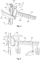
- FIG 2 illustrates the fastening of the load arm 114 to the safety rail 112.
- the load arm 114 is fastened to the safety rail 112 by means of the fastening section 116.
- the fastening section 116 has a fastening hook 130 which is provided to engage in an elongated opening 132, which can also be referred to as an elongated hole and is arranged on the rear side of the safety rail 112.
- the load arm 114 with its fastening section 116 and the fastening hook 130 is inserted slightly obliquely into the safety rail 112, which is designed as a so-called C-profile, and pushed slightly downwards into its fastened position.
- a locking bolt 134 is provided which, in the fastened position, engages in the same elongated hole 132 as the fastening hook 130.
- the fully inserted position is in the Figure 3 illustrated in a side view.
- FIG. 3 also illustrates that a plurality of fastening bores 138 are provided in the load arm 114, which provide different fastening positions for the pulley block 106 of the lifting means 104. Different mounting holes 138 can accommodate different weights. In addition, through a clever selection of the fastening bore 138, a favorable pulling direction can be selected when the work basket 102 is lifted.
- Figure 4 basically shows a side view of the situation of FIG Figure 1 . It can also be seen here that an actuating section 140 is fastened to a rope 142 of the pulley block 106, the rope 142 extending from a position above the working cage 102 through the working cage 102 to a position below the working cage 102. Correspondingly, the work cage 102 can be pulled from a position below this work cage 102 into a higher position and thus lifted. The work basket 102 is guided by lateral guide cheeks.
- the lifting means 104 can be correspondingly Provide secured hooks 144, which can also be generally referred to as snap hooks.
- Such a secured hook 144 is shown in FIG Figure 4 and also in the Figure 5 shown as an example in an enlargement.
- ladder holders 146 are also shown, by means of which the tower ladder 108 including safety rail 112 is attached to an inner tower wall, this ladder holder 146 also leading to a spacing between the tower ladder 108 and the tower wall concerned.
- Figure 5 shows a situation similar to that in Figure 4 shown, wherein the block and tackle 106 with its secured hook 144 is attached to other positions of the work basket 102. Accordingly, there is no attachment to the railing 118 according to FIG Figure 4 provided, but an attachment to a pivot axis 148 to pivot the platform 122 and to further support struts 150 of the work basket 102.
- the use of the pivot axis 148 and the support struts 150 to stop the secured hook 144 creates the possibility of the work cage 102 closer pulling the load arm 114 towards it. This is particularly important when the work cage 102 is to be lifted particularly high in the tower and in particular the uppermost tower segment to be worked on.
- the Figure 5 shows the work basket 102 in a partially sectioned view.
- the pulley block 106 is namely according to the situation of Figure 5 arranged in the work cage 102 and thus only recognizable through the sectioned illustration.
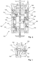
- Figure 6 shows the work cage 102 from a rear view, namely basically from the perspective of the tower wall to which the tower ladder 108 is attached.
- Figure 6 thus shows a view of a basket rear side 152, which has a number of fastening means.
- the work basket is fastened to the rear side 152 of the basket by means of six connecting means 154.
- Each connecting means 154 comprises a locking slide 156, with which the connection between the working cage 102 and the rear side 152 of the cage is made.
- the arrow 158 illustrates a movement for locking and the arrow 160 a movement for unlocking.
- three support brackets 162 are provided, which position the work basket in the height by resting it on a ladder rung 110.
- a support bracket 162 is shown in a side view.
- the support bracket has a support lever 164 which is in the Figure 7 is shown in two positions, namely in a horizontal rest position and an inclined, evasive position.
- the arrow 166 indicates an evasive movement into the evaded position. If the work cage is pulled upwards and the support bracket 162 passes a ladder rung 110, this upward movement of the work cage 102 and thus the support bracket 162 pushes the ladder rung 110 the support lever 164 into the evasive movement 160. If the upward movement is continued and the ladder rung 110 leaves the contact area with the support lever 164, then this support lever 164 pivots back in the pivoting movement according to the arrow 168.
- the support lever 164 strikes against a stop 170.
- a spring is arranged in the area of the pivot axis 172 of the support lever 164, which is not shown in the figures.
Landscapes
- Engineering & Computer Science (AREA)
- Architecture (AREA)
- Mechanical Engineering (AREA)
- Structural Engineering (AREA)
- Civil Engineering (AREA)
- General Engineering & Computer Science (AREA)
- Chemical & Material Sciences (AREA)
- Combustion & Propulsion (AREA)
- Life Sciences & Earth Sciences (AREA)
- Sustainable Energy (AREA)
- Sustainable Development (AREA)
- Physics & Mathematics (AREA)
- Transportation (AREA)
- Automation & Control Theory (AREA)
- Thermal Sciences (AREA)
- Wood Science & Technology (AREA)
- Materials Engineering (AREA)
- Electromagnetism (AREA)
- Wind Motors (AREA)
- Conveying And Assembling Of Building Elements In Situ (AREA)
- Types And Forms Of Lifts (AREA)
- Load-Engaging Elements For Cranes (AREA)
- Acyclic And Carbocyclic Compounds In Medicinal Compositions (AREA)
- Foundations (AREA)
- Lift-Guide Devices, And Elevator Ropes And Cables (AREA)
- Ladders (AREA)
- Yarns And Mechanical Finishing Of Yarns Or Ropes (AREA)
- Control And Other Processes For Unpacking Of Materials (AREA)
- Heat-Pump Type And Storage Water Heaters (AREA)
Description
- Die vorliegende Erfindung betrifft eine Arbeitsbühnenvorrichtung zum Arbeiten in veränderlicher Höhe in einem Turm oder Turmabschnitt einer Windenergieanlage und ein Verfahren zum Errichten eines Turms einer Windenergieanlage.
- Verfahren zum Errichten eines Turms einer Windenergieanlage, insbesondere eines Betonturms, sind grundsätzlich bekannt. Zunächst wird ein Betonfundament vorgesehen. Ein Betonturm in Fertigbauweise ist aus mehreren Turmsegmenten zusammengesetzt. Solche Turmsegmente können als rohrförmige und damit zylinderähnliche Elemente, nämlich im Gegensatz zu einem Zylinder mit leicht konischer Form, vorgesehen sein. Bei größeren Turmdurchmessern kommt auch eine Unterteilung in Umfangsrichtung in Betracht, so dass beispielsweise zwei im Querschnitt etwa halbkreisförmige Element oder andere teilkreisförmige Segmente zusammengesetzt werden.
- Zunächst werden ein Turmsegment oder mehrere Turmsegmente als erste unterste Turmebene auf dem Fundament aufgesetzt. Es ist wichtig, dass diese erste Ebene sehr sorgfältig ausgerichtet, nämlich ausnivelliert wird. Hierfür wird dieses erste Segment bzw. mehrere Segmente genau ausnivelliert und in dieser ausnivellierten Position zunächst zumindest provisorisch fixiert, um dann zwischen Fundament und diesem untersten Turmsegment bzw. diesen untersten Turmsegmenten eine Ausgleichsmasse einzufügen, die schließlich aushärtet und diese nivellierte Ausrichtung fixiert.
- Problematisch hierbei ist, dass die Aushärtung der Ausgleichsmasse eine gewisse Mindesttemperatur benötigt. Bei niedrigen Außentemperaturen um den Gefrierpunkt kann sich das Aushärten signifikant verlängern oder vollständig scheitern. Dies führt zum einen zu der Gefahr einer schlecht oder unvollständig ausgehärteten Ausgleichsmasse. Andererseits können durch das Abwarten einer verlängerten Aushärtedauer längere Standzeiten für beispielsweise einen zur Installation benötigten Kran resultieren. Ein solcher Kran, der bereits das/die erste(n) Turmsegment(e) auf das Fundament gehoben hat, bleibt für die Dauer des Aushärtens dieser Ausgleichsmasse ungenutzt. Es ergeben sich somit kostspielige zusätzliche Standzeiten des Krans.
- Im Weiteren wird der Turm sukzessive aufgebaut, indem weitere Turmsegmente auf den bis dahin aufgebauten Teilturm aufgesetzt werden. Die hierfür notwendigen Arbeiten entstehen somit zunehmend in höherer Höhe. Im Bereich der obersten Ebene des jeweils fertiggestellten Turmabschnitts wird somit regelmäßig ein Gerüst oder Arbeitsplattform angeordnet, auf dem Arbeiter des Aufbauteams das Aufsetzen eines neuen Turmsegmentes kontrollieren können. Hierbei muss insbesondere kontrolliert werden, dass das jeweilige neue Turmsegment an exakt der richtigen, vorgesehenen Position angeordnet wird. Mittels eines Kranes wird so jedes Turmsegment sukzessive etwa an seinen Platz gehoben und ein Kranführer führt eine Feinpositionierung des betreffenden Turmsegmentes aus. Die genaue Positionierung jedes Turmsegmentes wird dann von den Arbeitern des Aufbauteams auf der besagten Arbeitsplattform manuell, also mit Muskelkraft vorgenommen. Insbesondere muss das betreffende Turmsegment regelmäßig in die korrekte Position gedreht werden. Das Aufbaupersonal hält das so per Hand ausgerichtete Turmsegment in der korrekten Position und der Kranführer senkt das Turmsegment dann langsam ab, während das Aufbauteam dafür sorgt, dass die ausgerichtete Position beibehalten wird. Es ist dabei zu berücksichtigen, dass ein solches Turmsegment etwa 5 bis 120 t wiegen kann. Es muss somit trotz Einsatz großer Muskelkräfte eine sehr feine Positionierung vorgenommen werden.
- Dieses Verfahren zum Aufsetzen eines weiteren Turmsegmentes ist somit kompliziert, zeitund arbeitsaufwändig und weist eine gewisse Fehleranfälligkeit. Zudem besteht die Gefahr von Verletzungen für die Arbeiter vor Ort, insbesondere die Gefahr von Quetschungen.
- Ist das neue Turmsegment auf dem bis dahin errichteten Turm angeordnet, muss das Turmsegment von einer Traverse, mit der der Kran das Turmsegment gehoben hat, getrennt werden. Hierzu können Tragschlaufen, wie zu Schlaufen geformte Stahlseile an dem Turmsegment befestigt sein. Die Traverse wird dann von diesen Schlaufen gelöst, wie beispielsweise ausgehakt und die Stahlseilschlaufen als solche werden dann manuell von den Arbeitern auf der Arbeitsplattform von dem aufgesetzten Turmsegment entfernt. Auch dies ist aufwändig und erfordert einen recht hohen Personalaufwand einschließlich entsprechender Arbeitsplattform in der Höhe des bis dahin fertiggestellten Turms.
- Ganz allgemein sei auf die Dokumente
US 3,074,564 A ,DE 10 2009 023 538 A1 undDE 20 2010 000 868 U1 verwiesen. -
US 2009/0107062 A1 beschreibt ein Verfahren zum Anheben eines Turmsegments. -
DE 101 04 351 A1 beschreibt eine Arbeitsbühnenvorrichtung zum Aufnehmen einer Person zum Arbeiten in dem Turm in veränderlicher Höhe. - Der vorliegenden Erfindung liegt somit die Aufgabe zugrunde, wenigstens eines der oben aufgezeigten Probleme zu beheben oder zu verringern, insbesondere den Aufbau eines Turms einer Windenergieanlage effizienter zu gestalten, insbesondere den Aufbau eines Betonturms. Zumindest soll eine alternative Lösung vorgeschlagen werden.
- Erfindungsgemäß wird eine Arbeitsbühnenvorrichtung zum Arbeiten in veränderlicher Höhe in einem Turm oder Turmabschnitt einer Windenergieanlage gemäß Anspruch 1 vorgeschlagen. Diese Arbeitsbühnenvorrichtung ist zum Aufbauen eines Turmes vorgesehen und insoweit zur Verwendung in einem teilweise fertiggestellten Turm, der auch als Turmabschnitt bezeichnet werden kann. Die Arbeitsbühnenvorrichtung umfasst einen Arbeitskorb zum Aufnehmen einer Person zum Arbeiten in dem Turm in veränderlicher Höhe. Der Arbeitskorb ist insoweit dazu vorbereitet, insbesondere jeweils im Bereich des obersten zurzeit angeordneten Turmabschnitts bereitgestellt zu werden. Hierbei wird von einem Turm einer Windenergieanlage ausgegangen, der segmentweise zusammengesetzt wird, also insbesondere durch übereinander Anordnen von Turmsegmenten. Dies können vorzugsweise Turmsegmente eines Betonturms sein, also Betonsegmente. Eine Anwendung in einem Stahlturm kommt gleichwohl auch in Betracht.
- Die Arbeitsbühnenvorrichtung weist zudem einen Befestigungsabschnitt zum unfallsicheren Befestigen des Arbeitskorbs an einer mit einer Sicherheitsschiene versehenen Turmleiter auf. Der Befestigungsabschnitt muss also dazu ausgebildet sein, nicht nur den Arbeitskorb quasi beliebig an der Turmleiter zu befestigen, sondern in einer Art und Weise, dass unter Berücksichtigung von Unfallverhütungsvorschriften wenigstens ein Arbeiter darin sicher in der jeweiligen Höhe im Turm arbeiten kann und darf. Die Turmleiter, an der dieser Sicherheitskorb unfallsicher zu befestigen ist, weist eine Sicherheitsschiene auf in der ein Arbeiter im Turm sein Sicherheitsgeschirr bestimmungsgemäß und vorschriftsgemäß sichern kann. Hieran muss der Befestigungsabschnitt des Arbeitskorbs angepasst sein.
- Gemäß einer Ausführungsform weist der Arbeitskorb einen Bodenabschnitt auf und der Bodenabschnitt kann so geöffnet werden, dass eine Bodenöffnung entsteht, durch die eine erwachsene Person, nämlich eine Person eines Aufbauteams des Windenergieanlagenturms, den Arbeitskorb nach unten verlassen kann. Entsprechend kann der Arbeitskorb nach unten geöffnet werden und das Mitglied des Aufbauteams kann den Arbeitskorb insbesondere über die Turmleiter, an der der Arbeitskorb befestigt ist, nach unten verlassen.
- Vorzugsweise ist die Bodenöffnung so ausgebildet, dass die Person beim Verlassen des Arbeitskorbes durch die Bodenöffnung, wenn der Arbeitskorb an der Turmleiter befestigt ist, mit einem Sicherheitsgeschirr über einen Sicherheitsschlitten an der Sicherheitsschiene durchgängig gesichert bleiben kann, insbesondere dass die Person den Sicherheitsschlitten bei Verlassen des Arbeitskorbes in der Schiene führen kann. Mit anderen Worten wird beim Öffnen der Bodenöffnung die Sicherheitsschiene insoweit vollständig freigegeben. Die Person, die den Arbeitskorb nach unten verlassen will, kann sich somit mittels des Sicherheitsgeschirrs und dem entsprechenden Sicherheitsschlitten an der Sicherheitsschiene schon im Korb sichern, was ohnehin für den gesamten Aufenthalt im Arbeitskorb vorzusehen ist. Dann kann die Öffnung geöffnet werden, wobei die Person ununterbrochen gesichert bleibt. Schließlich kann die Person an der Turmleiter einfach nach unten aus dem Arbeitskorb die Leiter heruntersteigen. Der Sicherheitsschlitten wird dabei in ansonsten bekannter Weise in der Sicherheitsschiene geführt und es entsteht hierbei zu keinem Zeitpunkt eine für die Person ungesicherte Situation. Die Person ist während des gesamten Vorgangs durchgehend gesichert.
- Gemäß einer weiteren Ausführungsform wird vorgeschlagen, die Arbeitsbühnenvorrichtung mit einem Hebemittel zu versehen. Dieses Hebemittel ist zum Befestigen an derTurmleiter vorgesehen und zum Hochziehen des Arbeitskorbes entlang der mit der Sicherheitsschiene versehenen Turmleiter aus einer ersten Arbeitsposition in eine höher gelegene zweite Arbeitsposition.
- Vorzugsweise weist das Hebemittel einen Flaschenzug oder zumindest ein Umlenkmittel zum Umlenken eines Tragseils auf, wobei der Flaschenzug bzw. das Umlenkmittel zum Befestigen an der Turmleiter oder Sicherheitsschiene vorbereitet ist. Hierdurch ist es möglich, den Flaschenzug bzw. das Umlenkmittel oberhalb des Arbeitskorbes an derselben Turmleiter bzw. der damit verbundenen Sicherheitsschiene zu befestigen. Ein Ende eines Tragseils bzw. ein Ende des Flaschenzuges wird dann an einer bzw. mehreren entsprechenden Stellen des Arbeitskorbes befestigt und das andere Ende des Seils reicht zu der Person, die das Hebemittel betätigen soll. Hierbei kann diese Person zuvor den Arbeitskorb durch eine entsprechende Öffnung nach unten verlassen haben und unterhalb des Arbeitskorbes stehen. Das Seil kann durch diese Öffnung im Boden des Arbeitskorbes zu der Person reichen. Diese Person kann nun an dem Seil den Arbeitskorb nach oben in eine höher gelegene Arbeitsposition ziehen. Dies ist insbesondere vorteilhaft beim Aufbauen eines Windenergieanlagenturmes aus einzelnen Turmsegmenten, indem auf die beschriebene Art und Weise der Arbeitskorb jeweils sukzessive in den Bereich des oberen Turmsegmentes, insbesondere in die Nähe der Oberkante des obersten Turmsegmentes bewegt wird, weil dort Arbeiten auszuführen sind, wenn dort das nächste Turmsegment aufgesetzt werden soll. Vorzugsweise werden hierbei Turmsegmente mit vormontierten Turmleiterabschnitten verwendet.
- Nachfolgend wird die Erfindung an Hand von Ausführungsbeispielen unter Bezugnahme auf die begleitenden Figuren beispielhaft erläutert.
- Figur 1
- zeigt eine Arbeitsbühnenvorrichtung in einer perspektivischen Ansicht.
- Figur 2
- zeigt ein Befestigungselement der Arbeitsbühnenvorrichtung der
Figur 1 vor. bzw. nach dem Verbinden mit einer Sicherheitsschiene. - Figur 3
- zeigt das Verbindungselement der
Figur 2 in einem mit der Sicherheitsschiene verbundenen Zustand. - Figur 4
- zeigt eine Arbeitsbühnenvorrichtung in einer seitlichen Ansicht.
- Figur 5
- zeigt eine Arbeitsbühnenvorrichtung in einer seitlichen, teilweise geschnittenen Ansicht gemäß einer weiteren Ausführungsform.
- Figur 6
- zeigt einen Teil einer Arbeitsbühnenvorrichtung in einer Rückansicht zusammen mit einer Turmleiter.
- Figur 7
- zeigt eine Auflagevorrichtung zum Halten der Arbeitsbühnenvorrichtung an einer Turmleiter.
- Die Arbeitsbühnenvorrichtung 100 der
Figur 1 umfasst einen Arbeitskorb 102 und ein Hebemittel 104, das einen Flaschenzug 106 aufweist. Die Arbeitsbühnenvorrichtung 100 ist dabei an einer Turmleiter 108 befestigt, die mit Leitersprossen 110 und einer Sicherheitsschiene 112 versehen ist. Das Hebemittel 104 weist hierfür einen Lastarm 114 auf, der mittels eines Befestigungsabschnitts 116 an der Sicherheitsschiene 112 verschiebungssicher befestigt ist. An dem Lastarm 14 ist der Flaschenzug 106 befestigt und zudem ist er an dem Arbeitskorb 102 befestigt, der somit mittels des Flaschenzuges in eine höhere Position gezogen werden kann. - Der Arbeitskorb 102 ist ebenfalls an der Turmleiter 108 verschiebungssicher in einer Arbeitsposition befestigt. Der Flaschenzug 106 bzw. das Hebemittel 104 insgesamt soll den Arbeitskorb 102 nur beim Versetzen desselben in eine höhere Position halten und heben. Damit soll das Hebemittel 104 den Arbeitskorb 102 somit auch im Wesentlichen nur in unbelastetem Zustand, also ohne Arbeitspersonal halten und heben.
- Der Arbeitskorb 102 weist ein Geländer 118 mit diversen Anschlagpunkten zum Befestigen des Flaschenzuges 106 zum Heben des Arbeitskorbs 102 auf. Das Geländer 118 ist ansonsten dazu vorgesehen, ein Herausfallen einer Person aus dem Arbeitskorb 102 zu verhindern. Dies wird durch einige Schutzwände 120 unterstützt.
- Der Arbeitskorb 102 weist zudem eine klappbare Plattform 122 auf, die als Boden bzw. Bodenabschnitt des Arbeitskorbs 102 dient. In der
Figur 1 ist die Plattform 122 in einer zur Seite geklappten Position dargestellt, in der eine Person den Arbeitskorb 102 nach unten verlassen kann. Hierfür gibt die weggeklappte Plattform 122 eine entsprechende Bodenöffnung 124 frei. Die Klapprichtung der Plattform ist durch den Pfeil 126 angedeutet. Weiterhin ist ein schwenkbarer Werkzeugkasten 128 vorgesehen, der bei Bedarf in den Arbeitskorb 102 hinein oder aus ihm heraus geschwenkt werden kann. Gegebenenfalls kann es aus Platzgründen sinnvoll sein, beim Verändern der Position des Arbeitskorbs 102 mittels des Hebemittels 104 den Werkzeugkasten 128 in den Arbeitskorb 102 hinein zu schwenken. Während Arbeiten in dem Arbeitskorb 102 bzw. aus dem Arbeitskorb 102 heraus geführt werden, kann ein Verschwenken des Werkzeugkastens 128 in eine Position außerhalb des Arbeitskorbes 102 in dem Arbeitskorb 102 zusätzlichen Platz schaffen. -
Figur 2 veranschaulicht die Befestigung des Lastarms 114 an der Sicherheitsschiene 112. Der Lastarm 114 wird dabei mittels des Befestigungsabschnittes 116 an der Sicherheitsschiene 112 befestigt. Hierzu weist der Befestigungsabschnitt 116 einen Befestigungshaken 130 auf, der dazu vorgesehen ist, in eine längliche Öffnung 132 einzugreifen, die auch als Langloch bezeichnet werden kann und an der Rückseite der Sicherheitsschiene 112 angeordnet ist. Zum Befestigen wird der Lastarm 114 mit seinem Befestigungsabschnitt 116 und dem Befestigungshaken 130 leicht schräg in die Sicherheitsschiene 112, die als sogenanntes C-Profil ausgeführt ist, eingeführt und etwas nach unten in ihre befestigte Position geschoben. Zum Verhindern des Wiederlösens ist ein Rastbolzen 134 vorgesehen, der in der befestigten Position in dasselbe Langloch 132 eingreift wie der Befestigungshaken 130. Die vollständig eingesetzte Position wird in derFigur 3 in einer Seitenansicht verdeutlicht. - Um den Lastarm 114 wieder aus der Sicherheitsschiene 112 zu lösen, müsste der Rastbolzen 134 manuell an seinem Betätigungskopf 136 durch Ziehen gelöst werden. Die
Figur 3 veranschaulicht zudem, dass in dem Lastarm 114 mehrere Befestigungsbohrungen 138 vorgesehen sind, die verschiedene Befestigungspositionen für den Flaschenzug 106 des Hebemittels 104 vorsehen. Unterschiedliche Befestigungsbohrungen 138 können unterschiedliche Gewichte aufnehmen. Zudem kann durch eine geschickte Wahl der Befestigungsbohrung 138 eine günstige Zugrichtung beim Heben des Arbeitskorbes 102 gewählt werden. -
Figur 4 zeigt im Grunde eine Seitenansicht der Situation derFigur 1 . Es ist hierbei zudem zu erkennen, dass ein Betätigungsabschnitt 140 an einem Seil 142 des Flaschenzuges 106 befestigt ist, wobei das Seil 142 von einer Position oberhalb des Arbeitskorbs 102 durch den Arbeitskorb 102 hindurch an eine Position unterhalb des Arbeitskorbes 102 reicht. Entsprechend kann der Arbeitskorb 102 von einer Position aus, die unterhalb dieses Arbeitskorbes 102 liegt, in eine höhere Position gezogen und damit gehoben werden. Der Arbeitskorb 102 wird hierbei durch seitliche Führungswangen geführt. Zum Befestigen an dem Arbeitskorb 102, insbesondere an dem Geländer 118 kann das Hebemittel 104 entsprechende gesicherte Haken 144 vorsehen, die auch allgemein als Karabinerhaken bezeichnet werden können. Ein solcher gesicherter Haken 144 ist in derFigur 4 und auch in derFigur 5 beispielhaft in einer Vergrößerung dargestellt. Im Übrigen sind in denFiguren 2 ,4 und 5 auch Leiterhalterungen 146 dargestellt, mittels derer die Turmleiter 108 einschließlich Sicherheitsschiene 112 an einer Turminnenwand befestigt wird, wobei diese Leiterhalterung 146 auch zu einem Abstand zwischen der Turmleiter 108 und der betreffenden Turmwand führt. -
Figur 5 zeigt eine Situation ähnlich der inFigur 4 dargestellten, wobei der Flaschenzug 106 mit seinen gesicherten Haken 144 an anderen Positionen des Arbeitskorbes 102 befestigt ist. Demnach ist keine Befestigung an dem Geländer 118 gemäßFigur 4 vorgesehen, sondern eine Befestigung an einer Schwenkachse 148, um die Plattform 122 zu schwenken ist und an weiteren Haltestreben 150 des Arbeitskorbes 102. Die Verwendung der Schwenkachse 148 und der Haltestreben 150 zum Anschlag der gesicherten Haken 144 schafft die Möglichkeit, den Arbeitskorb 102 näher an den Lastarm 114 heran zu ziehen. Dies ist besonders dann wichtig, wenn der Arbeitskorb 102 besonders hoch in dem Turm und insbesondere dem obersten gerade zu bearbeitenden Turmsegment gehoben werden soll. Gerade beim Aufbau eines Turmes aus diversen Segmenten kann es vorteilhaft sein, den Arbeitskorb 102 möglichst hoch in dem Turmsegment zu ziehen, um eine bessere Arbeitsposition beim Aufsetzen eines weiteren Turmsegments zu haben. DieFigur 5 zeigt dabei den Arbeitskorb 102 in einer teilweise geschnittenen Ansicht. Der Flaschenzug 106 ist nämlich gemäß der Situation derFigur 5 in dem Arbeitskorb 102 angeordnet und somit erst durch die geschnittene Darstellung erkennbar. -
Figur 6 zeigt den Arbeitskorb 102 aus einer Rückansicht, nämlich im Grunde aus Sicht der Turmwand an der die Turmleiter 108 befestigt ist.Figur 6 zeigt somit einen Blick auf eine Korbrückseite 152, die eine Reihe von Befestigungsmitteln aufweist. Der Arbeitskorb ist mittels sechs Verbindungsmitteln 154 an der Korbrückseite 152 befestigt. Jedes Verbindungsmittel 154 umfasst dabei einen Verriegelungsschieber 156, mit dem die Verbindung zwischen Arbeitskorb 102 und Korbrückseite 152 vorgenommen wird. Der Pfeil 158 veranschaulicht dabei eine Bewegung zum Verriegeln und der Pfeil 160 eine Bewegung zum Entriegeln. - Zudem sind drei Auflagehalterungen 162 vorgesehen, die den Arbeitskorb durch Auflage auf jeweils einer Leitersprosse 110 in der Höhe positionieren.
- In der Detailansicht der
Figur 7 ist eine Auflagehalterung 162 in einer Seitenansicht dargestellt. Die Auflagehalterung weist einen Auflagehebel 164 auf, der in derFigur 7 in zwei Positionen dargestellt ist, nämlich in einer waagerechten Ruheposition und einer schrägen, ausweichenden Position. Der Pfeil 166 deutet auf eine ausweichende Bewegung in die ausgewichene Position. Wird der Arbeitskorb nach oben gezogen und passiert dabei die Auflagehalterung 162 eine Leitersprosse 110, so wird durch diese Aufwärtsbewegung des Arbeitskorbes 102 und damit der Auflagehalterung 162 die Leitersprosse 110 den Auflagehebel 164 in die Ausweichbewegung 160 schieben. Wird die Aufwärtsbewegung fortgesetzt und verlässt dabei die Leitersprosse 110 den Kontaktbereich mit dem Auflagehebel 164, so schwenkt dieser Auflagehebel 164 in der Schwenkbewegung gemäß dem Pfeil 168 zurück. Dabei schlägt der Auflagehebel 164 gegen einen Anschlag 170. Hierzu ist eine Feder im Bereich der Schwenkachse 172 des Auflagehebels 164 angeordnet, die in den Figuren jedoch nicht dargestellt ist. - Wird der Arbeitskorb 102 nun wieder leicht abgesenkt, so kommt der Auflagehebel 164 auf der betreffenden Leitersprosse 110 zu liegen und hält den Arbeitskorb 102. Absenkbewegung wird mit dem Pfeil 174 veranschaulicht.
- Soll der Arbeitskorb 102 weiter abgesenkt werden, so muss ein Zurückschwenken des Auflagehebels 164 durch eine entsprechend vorgesehene Blockiervorrichtung verhindert werden. Eine solche Blockiervorrichtung ist vorhanden, wird in den Figuren jedoch nicht veranschaulicht.
Claims (7)
- Arbeitsbühnenvorrichtung (100) zum Arbeiten in veränderlicher Höhe in einem Turm oder Turmabschnitt einer Windenergieanlage, umfassend:- einen Arbeitskorb (102) zum Aufnehmen einer Person zum Arbeiten in dem Turm in veränderlicher Höhe und- einen Befestigungsabschnitt (116) zum unfallsicheren Befestigen des Arbeitskorbs (102) an einer mit einer Sicherheitsschiene (112) versehenen Turmleiter (108) und- ein Hebemittel (104) zum Befestigen an der Turmleiter (108), zum Hochziehen des Arbeitskorbes entlang der mit der Sicherheitsschiene (112) versehenen Turmleiter (108) aus einer ersten Arbeitsposition in eine höher als die erste Arbeitsposition gelegene zweite Arbeitsposition,
wobei das Hebemittel (104) einen Lastarm (114) aufweist, der mittels des Befestigungsabschnitts (116) an der Sicherheitsschiene (112) verschiebungssicher befestigt ist,
wobei der Befestigungsabschnitt (115) einen Befestigungshaken (130) aufweist, der vorgesehen ist, um in eine an einer Rückseite der Sicherheitsschiene (112) angeordnete längliche Öffnung (132) einzugreifen. - Arbeitsbühnenvorrichtung (100) nach Anspruch 1, wobei der Arbeitskorb (102) einen Bodenabschnitt aufweist und der Bodenabschnitt so geöffnet werden kann, dass eine Bodenöffnung entsteht, durch die eine erwachsene Person den Arbeitskorb (102) nach unten verlassen kann.
- Arbeitsbühnenvorrichtung (100) nach Anspruch 2, wobei die Bodenöffnung so ausgebildet ist, dass die Person beim Verlassen des Arbeitskorbes (102) durch die Bodenöffnung, wenn der Arbeitskorb (102) an der Turmleiter (108) befestigt ist, mit einem Sicherheitsgeschirr über einen Sicherheitsschlitten an der Sicherheitsschiene (112) durchgängig gesichert bleiben kann, insbesondere dass die Person den Sicherheitsschlitten beim Verlassen des Arbeitskorbes (102) in der Schiene führen kann.
- Arbeitsbühnenvorrichtung (100) nach Anspruch 1, wobei das Hebemittel (104) einen Flaschenzug (106) und/oder ein Umlenkmittel zum Umlenken eines Tragseils aufweist, wobei der Flaschenzug (106) bzw. das Umlenkelement zum Befestigen an der Turmleiter (108) oder Sicherheitsschiene (112) vorbereitet ist.
- Arbeitsbühnenvorrichtung (100) nach einem der Ansprüche 1 bis 4, ferner mit drei Auflagehalterungen (162), die den Arbeitskorb (102) durch Auflage auf jeweils einer Leitersprosse (110) in der Höhe positionieren.
- Verfahren zum Errichten eines Turms einer Windenergieanlage umfassend die Schritte:- Anordnen eines ersten Turmsegmentes auf einem Fundament, und- Anordnen einer Arbeitsbühnenvorrichtung (100) nach einem der Ansprüche 1 bis 6 zum Arbeiten in veränderlicher Höhe in dem Turm bzw. Turmabschnitt an einer Turmleiter (108),- Aufsetzen eines weiteren Turmsegments auf das erste Turmsegment, und- Versetzen eines Hebemittels (104) der Arbeitsbühnenvorrichtung (100) an einen oberen Bereich der Turmleiter (108) in dem weiteren Turmsegment und Hochziehen eines Arbeitskorbs (102) der Arbeitsbühnenvorrichtung (100) entlang der Turmleiter (108) in den oberen Bereich der Turmleiter (108), insbesondere manuell.
- Verfahren nach Anspruch 6, ferner mit den Schritten:
Anordnen einer Wärmvorrichtung am Turmsegment und Abdecken eines ringförmig umlaufenden Stoßbereichs zwischen dem Turmsegment und dem Turmfundament.
Applications Claiming Priority (3)
| Application Number | Priority Date | Filing Date | Title |
|---|---|---|---|
| DE102011003164A DE102011003164A1 (de) | 2011-01-26 | 2011-01-26 | Verfahren und Vorrichtung zum Errichten eines Turms einer Windenergieanlage |
| PCT/EP2012/050729 WO2012101023A2 (de) | 2011-01-26 | 2012-01-18 | Verfahren und vorrichtung zum errichten eines turms einer windenergieanlage |
| EP12700685.6A EP2556008B1 (de) | 2011-01-26 | 2012-01-18 | Vorrichtung und verfahren zum errichten eines turms einer windenergieanlage |
Related Parent Applications (2)
| Application Number | Title | Priority Date | Filing Date |
|---|---|---|---|
| EP12700685.6A Division-Into EP2556008B1 (de) | 2011-01-26 | 2012-01-18 | Vorrichtung und verfahren zum errichten eines turms einer windenergieanlage |
| EP12700685.6A Division EP2556008B1 (de) | 2011-01-26 | 2012-01-18 | Vorrichtung und verfahren zum errichten eines turms einer windenergieanlage |
Publications (2)
| Publication Number | Publication Date |
|---|---|
| EP2803616A1 EP2803616A1 (de) | 2014-11-19 |
| EP2803616B1 true EP2803616B1 (de) | 2021-06-16 |
Family
ID=45509505
Family Applications (4)
| Application Number | Title | Priority Date | Filing Date |
|---|---|---|---|
| EP14180218.1A Active EP2805909B1 (de) | 2011-01-26 | 2012-01-18 | Wärmevorrichtung |
| EP14180212.4A Active EP2803616B1 (de) | 2011-01-26 | 2012-01-18 | Arbeitsbühnenvorrichtung zum Arbeiten in verändlicher Höhe und Verfahren dafür |
| EP12700685.6A Active EP2556008B1 (de) | 2011-01-26 | 2012-01-18 | Vorrichtung und verfahren zum errichten eines turms einer windenergieanlage |
| EP14180214.0A Active EP2803617B1 (de) | 2011-01-26 | 2012-01-18 | Verfahren zum Errichten eines Turms einer Windenergieanlage |
Family Applications Before (1)
| Application Number | Title | Priority Date | Filing Date |
|---|---|---|---|
| EP14180218.1A Active EP2805909B1 (de) | 2011-01-26 | 2012-01-18 | Wärmevorrichtung |
Family Applications After (2)
| Application Number | Title | Priority Date | Filing Date |
|---|---|---|---|
| EP12700685.6A Active EP2556008B1 (de) | 2011-01-26 | 2012-01-18 | Vorrichtung und verfahren zum errichten eines turms einer windenergieanlage |
| EP14180214.0A Active EP2803617B1 (de) | 2011-01-26 | 2012-01-18 | Verfahren zum Errichten eines Turms einer Windenergieanlage |
Country Status (25)
| Country | Link |
|---|---|
| US (1) | US9534416B2 (de) |
| EP (4) | EP2805909B1 (de) |
| JP (3) | JP5860902B2 (de) |
| KR (3) | KR101665169B1 (de) |
| CN (3) | CN105020228B (de) |
| AR (1) | AR085029A1 (de) |
| AU (1) | AU2012210698B2 (de) |
| BR (1) | BR112013018604A2 (de) |
| CA (1) | CA2823982C (de) |
| CL (1) | CL2013002121A1 (de) |
| CY (2) | CY1116401T1 (de) |
| DE (1) | DE102011003164A1 (de) |
| DK (4) | DK2556008T3 (de) |
| ES (3) | ES2541637T3 (de) |
| HR (2) | HRP20150718T1 (de) |
| HU (2) | HUE030304T2 (de) |
| LT (1) | LT2805909T (de) |
| MX (1) | MX336620B (de) |
| PL (2) | PL2556008T3 (de) |
| PT (3) | PT2556008E (de) |
| RS (2) | RS55347B1 (de) |
| SI (2) | SI2805909T1 (de) |
| TW (1) | TWI480453B (de) |
| WO (1) | WO2012101023A2 (de) |
| ZA (1) | ZA201304951B (de) |
Families Citing this family (52)
| Publication number | Priority date | Publication date | Assignee | Title |
|---|---|---|---|---|
| US9758984B2 (en) * | 2012-11-08 | 2017-09-12 | Besterra Co., Ltd. | Aggregate stack demolishing scaffold apparatus and method for demolishing aggregate stack using the apparatus |
| DE102012221453A1 (de) * | 2012-11-23 | 2014-05-28 | Wobben Properties Gmbh | Greifeinrichtung zum Handhaben von Bewehrungskörben für Turmsegmente einer Windenergieanlage |
| EP2824057B1 (de) | 2013-07-11 | 2017-06-28 | Siemens Aktiengesellschaft | Anheben eines Mastsegments |
| ES2901435T3 (es) * | 2013-07-17 | 2022-03-22 | Alimak Group Man Ab | Sistema elevador |
| CN103939298B (zh) * | 2014-04-01 | 2016-04-13 | 北京金风科创风电设备有限公司 | 用于混凝土塔架拼装的结构 |
| CN104213714B (zh) * | 2014-08-27 | 2016-03-09 | 中国建筑第二工程局有限公司 | 一种超大型屋架的提升吊点加固结构及吊装施工方法 |
| AU2015330437A1 (en) * | 2014-10-06 | 2017-04-27 | Vestas Wind Systems A/S | Hinged tower segments and transport method |
| CN104631839B (zh) * | 2015-01-29 | 2016-08-24 | 浙江勤业建工集团有限公司 | 超高超重大跨度空中连廊整体提升施工方法 |
| CN104803308B (zh) * | 2015-04-28 | 2017-01-18 | 中国水利水电第八工程局有限公司 | 用于钢管加劲环拼装的吊装装置 |
| CN105119190A (zh) * | 2015-08-27 | 2015-12-02 | 国家电网公司 | 一种自锁式瓷片式绝缘子吊装架 |
| CN105119189A (zh) * | 2015-08-27 | 2015-12-02 | 国家电网公司 | 一种超长瓷片式绝缘子串吊装架 |
| MX2018002590A (es) * | 2015-08-31 | 2018-11-09 | Wind Tower Tech Llc | Sistema y metodo para instalar un tendon tensado en una torre de turbina de viento. |
| DE102016200160A1 (de) | 2016-01-08 | 2017-07-13 | Wobben Properties Gmbh | Hebevorrichtung zum Heben einer Komponente einer Windenergieanlage und Verfahren zum Montieren von Komponenten einer Windenergieanlage |
| GB2551481A (en) * | 2016-06-08 | 2017-12-27 | John Reed Patrick | A sheeting system |
| CN106337785B (zh) * | 2016-09-29 | 2019-01-25 | 中车株洲电力机车研究所有限公司 | 风力发电机组风轮内葫芦辅助拆装工具及方法 |
| US11506179B2 (en) | 2016-11-11 | 2022-11-22 | Siemens Gamesa Renewable Energy A/S | Transport assembly |
| US10704535B2 (en) | 2016-11-23 | 2020-07-07 | Mhi Vestas Offshore Wind A/S | Method and assembly for aligning wind turbine structural parts |
| CN106640558B (zh) * | 2016-12-30 | 2019-04-12 | 北京金风科创风电设备有限公司 | 风力涡轮机的变桨轴承、叶片、叶轮及连接方法 |
| CN106903014A (zh) * | 2017-02-28 | 2017-06-30 | 李金平 | 一种喷涂行业用定心转盘 |
| CN106744252B (zh) * | 2017-03-27 | 2018-09-21 | 江苏中车电机有限公司 | 用于mw级直驱永磁风力发电机转子吊运工装及使用方法 |
| CN107152021B (zh) * | 2017-06-06 | 2023-03-28 | 中国石油天然气集团公司 | 一种u形管桩护甲安装工具 |
| EP3450752B1 (de) * | 2017-09-04 | 2020-06-17 | Siemens Gamesa Renewable Energy A/S | Windturbine mit einer zugangsanordnung für eine gondel |
| CN107953975B (zh) * | 2017-11-22 | 2023-06-02 | 自然资源部第二海洋研究所 | 船用机械臂止荡机构 |
| NL2020809B1 (en) * | 2018-04-23 | 2019-10-31 | Ihc Holland Ie Bv | A lifting tool |
| CN109058052B (zh) * | 2018-08-29 | 2020-08-21 | 江苏仕沃精密机械科技有限公司 | 新能源风力发电设备的集成式固定安装架 |
| CN111283863A (zh) * | 2018-12-06 | 2020-06-16 | 深圳京创重工特种工程有限公司 | 塔筒的模具组件以及脱模方法 |
| CN111283862A (zh) * | 2018-12-06 | 2020-06-16 | 深圳京创重工特种工程有限公司 | 用于塔筒模具组件的吊架 |
| CN109809287B (zh) * | 2019-03-18 | 2020-05-12 | 哈尔滨电机厂有限责任公司 | 一种用于周向装配的对称起吊装置的使用方法 |
| CN110565934A (zh) * | 2019-07-26 | 2019-12-13 | 江苏兴厦建设工程集团有限公司 | 一种建筑外墙悬吊式人货电梯施工平台及其安装方法 |
| DE102019122021A1 (de) * | 2019-08-15 | 2021-02-18 | Wobben Properties Gmbh | Montagetraverse und Verfahren zum Einziehen von kabelförmigen Elementen, insbesondere von Spanngliedern, entlang eines Turms einer Windenergieanlage |
| JP6882795B2 (ja) * | 2019-09-30 | 2021-06-02 | 村田油圧機械株式会社 | 連絡ブリッジ |
| JP6798720B1 (ja) * | 2019-09-30 | 2020-12-09 | 村田油圧機械株式会社 | 連絡ブリッジ用の伸縮アクチュエータ |
| JP6798721B1 (ja) * | 2019-09-30 | 2020-12-09 | 村田油圧機械株式会社 | 連絡ブリッジ用の水平回動アクチュエータ |
| CN110748135B (zh) * | 2019-10-14 | 2024-09-13 | 中建二局安装工程有限公司 | 一种临时操作平台体系及其施工方法 |
| CN111039152B (zh) * | 2019-12-31 | 2021-01-26 | 烟台腾泰环保建材有限公司 | 一种混凝土预制构件 |
| CN111980865B (zh) * | 2020-07-29 | 2021-11-12 | 上海市机电设计研究院有限公司 | 减小预制混凝土筒片错动的筒节吊装方法 |
| CN111997432B (zh) * | 2020-07-29 | 2021-12-14 | 上海市机电设计研究院有限公司 | 预制混凝土塔筒的施工平台提升装置及方法 |
| CN113023540B (zh) * | 2021-03-15 | 2022-03-01 | 合肥中科离子医学技术装备有限公司 | 一种用于回旋加速器整机的吊装运输一体式装置 |
| CN113090037A (zh) * | 2021-04-01 | 2021-07-09 | 浙江明康工程咨询有限公司 | 一种卸料平台的预警方法及系统 |
| CN113503047A (zh) * | 2021-07-31 | 2021-10-15 | 中冶(上海)钢结构科技有限公司 | 钢结构提升过程中牵引调整高空位置偏移的方法 |
| CN113756647B (zh) * | 2021-09-04 | 2022-11-08 | 中铁十五局集团有限公司 | 一种线路铁塔分段结构的施工方法及其装置 |
| CN113944313B (zh) * | 2021-11-03 | 2023-04-11 | 上海建工五建集团有限公司 | 悬挑型钢顶撑限位装置、悬挑钢平台及其施工方法 |
| CN114108996B (zh) * | 2021-11-26 | 2023-06-06 | 中煤西安设计工程有限责任公司 | 一种无楼板砖砌填充墙的施工装置及方法 |
| US20230417072A1 (en) * | 2022-06-27 | 2023-12-28 | JMR Technologies | Thermally Insulated Tilt-Up Wall Lift and Brace Assemblies |
| CN115285854B (zh) * | 2022-09-28 | 2022-12-02 | 中国能源建设集团山西电力建设有限公司 | 大型圆柱形罐体的低空拼装分节抬升的装配方法 |
| CN115788785B (zh) * | 2022-11-11 | 2026-01-02 | 东方电气风电股份有限公司 | 一种用于直立式风电机组的桁架及其安装方法 |
| CN116123037A (zh) * | 2022-12-31 | 2023-05-16 | 上海电气研砼(木垒)建筑科技有限公司 | 一种塔筒环片拼装辅助装置 |
| DE102023120009A1 (de) * | 2023-07-27 | 2025-01-30 | Bettels Betonfertigteile GmbH | Turmsegment für einen Turm einer Windenergieanlage sowie betreffender Turm |
| CN117344983B (zh) * | 2023-10-09 | 2025-12-12 | 中国十七冶集团有限公司 | 一种预制轻质隔墙alc板垂直运输装置及方法 |
| CN117627385B (zh) * | 2024-01-03 | 2026-01-27 | 陕西建工新能源(定边)风机设备制造有限公司 | 一种钢混塔架辅助安装平台 |
| CN117703164B (zh) * | 2024-02-05 | 2024-04-09 | 辽宁省送变电工程有限公司 | 高低铁塔塔腿段组立自动提升装置 |
| CN120817529B (zh) * | 2025-09-18 | 2025-11-25 | 宁波合力科技股份有限公司 | 一种模具吊装装置 |
Family Cites Families (52)
| Publication number | Priority date | Publication date | Assignee | Title |
|---|---|---|---|---|
| US3074564A (en) * | 1961-03-01 | 1963-01-22 | Chicago Bridge & Iron Co | Mast extension jib |
| DE1251803B (de) * | 1963-12-05 | 1967-10-12 | Siemens Aktiengesellschaft, Berlin und München München | Verfah ren und Einrichtung zum Regenerieren von phasenmodulierten Impulsfolgen |
| CH508507A (de) * | 1969-05-28 | 1971-06-15 | Von Roll Ag | Zahnstange für eine Fahrschiene für Hängebahnen |
| JPS5830882Y2 (ja) * | 1978-06-21 | 1983-07-08 | 住友金属工業株式会社 | 大型コンクリ−ト構造体用吊筋 |
| SU958296A1 (ru) | 1980-06-12 | 1982-09-15 | Республиканское Проектно-Технологическое Производственное Объединение "Росоргтехстрой" | Захват-кантователь дл изделий с цапфами |
| DE8424193U1 (de) * | 1984-08-16 | 1985-12-12 | Ernst Peiniger GmbH Unternehmen für Bautenschutz, 4300 Essen | Arbeitsplatzverschlag |
| DE59405796D1 (de) * | 1994-06-23 | 1998-05-28 | Halfen Gmbh & Co Kg | Transportanker, insbesondere für Betonfertigteile und in den Transportanker einschraubbarer Lastaufnehmer |
| TW253924B (en) | 1994-09-14 | 1995-08-11 | Nippon Kotetsu Kokusai Kk | Elevatable work facility |
| JPH08303441A (ja) * | 1995-05-01 | 1996-11-19 | Aioi Seiki Kk | ガイド兼ロック機構付きコネクタ装置 |
| AU741284B2 (en) * | 1998-02-04 | 2001-11-29 | Stephen L. Heston | Palletizing device |
| DE19857744B4 (de) * | 1998-12-15 | 2007-05-16 | Schuler Pressen Gmbh & Co | Presse mit Stempelverstellung, insbesondere zur Massivumformung |
| JP2000283019A (ja) * | 1999-03-31 | 2000-10-10 | Pc Bridge Co Ltd | コンクリート製風車支持タワー及びその構築方法 |
| DE10025074B4 (de) | 2000-05-20 | 2006-11-09 | Hailo-Werk Rudolf Loh Gmbh & Co. Kg | Einrichtung zum Befördern von Personen |
| US6782667B2 (en) | 2000-12-05 | 2004-08-31 | Z-Tek, Llc | Tilt-up and telescopic support tower for large structures |
| DE10104351A1 (de) * | 2001-02-01 | 2002-08-22 | Ingenieurgesellschaft Foerder | Aufzug mit auf der Aufzugskabine mitfahrender Antriebseinheit und Steuereinheit |
| US6625940B2 (en) * | 2001-02-02 | 2003-09-30 | Wallace D. Sanger | Concrete building module with module lifting means and method |
| DE10160022A1 (de) * | 2001-12-06 | 2003-06-18 | Gen Electric | Verfahren zum Herstellen eines Turms einer Windkraftanlage, mit diesem Verfahren hergestellter Turm und Bauelemente zur Herstellung eines Turms |
| DE10163538B4 (de) * | 2001-12-21 | 2004-09-30 | Norbert Plambeck | Vorrichtung und Verfahren zum Transport und zur Errichtung von Offshore-Windenergieanlagen |
| GB2394498B (en) | 2002-10-23 | 2006-08-09 | Engineering Business Ltd | Mounting of offshore structures |
| JP2004156478A (ja) * | 2002-11-05 | 2004-06-03 | Kashiwabara Painting Works Co Ltd | 独立型塔体構造物の作業用足場装置及び作業用足場設置工法 |
| CN100445552C (zh) * | 2003-12-30 | 2008-12-24 | Pp能源有限责任公司 | 用于抵达位于地面上方的结构的设备 |
| GB0500619D0 (en) | 2005-01-13 | 2005-02-23 | Severfield Rowen Plc | Improvements relating to construction |
| CN101614083B (zh) * | 2005-01-19 | 2014-09-24 | Iti苏格兰有限公司 | 夹具、自移式爬升装置和联接夹具与管形件的方法 |
| US20060213145A1 (en) * | 2005-03-22 | 2006-09-28 | Haller Mark E | Lattice-skin hybrid tower |
| JP2007046292A (ja) * | 2005-08-09 | 2007-02-22 | Oriental Construction Co Ltd | タワー構築用ブロック |
| JP4701047B2 (ja) * | 2005-09-07 | 2011-06-15 | 株式会社竹中工務店 | 風力発電タワーの構築方法 |
| TWM296876U (en) | 2006-03-07 | 2006-09-01 | Runhorn Pretech Eng Co Ltd | Wall structure preset hanging point |
| EP2038550B2 (de) * | 2006-06-29 | 2022-09-14 | Vestas Wind Systems A/S | Turmkonstruktion für eine windturbine |
| ATE491665T1 (de) * | 2006-06-30 | 2011-01-15 | Vestas Wind Sys As | Hubeinrichtung zur handhabung einer windturbinenkomponente und verfahren zur handhabung einer windturbinenkomponente |
| CN101535582B (zh) * | 2006-10-02 | 2013-03-27 | 通用风能有限责任公司 | 用于构建和包覆风力涡轮机塔架的提升系统及装置 |
| KR20090011746A (ko) * | 2007-07-27 | 2009-02-02 | 주식회사 피엔에이치 | 자동 개방형 샤클 조립체의 안전장치 |
| AU2008221636A1 (en) * | 2007-10-11 | 2009-04-30 | General Electric Company | Wind tower and method of assembling the same |
| WO2009101697A1 (ja) * | 2008-02-15 | 2009-08-20 | Sakuraigiken Co., Ltd. | 風力発電設備の風車羽根のメンテナンス工法及びメンテナンス装置 |
| US20090223163A1 (en) | 2008-03-10 | 2009-09-10 | Shu Ching Quek | Wind Turbine Tower Including An Induction Brazed Joint And A Method Of Fabricating The Wind Turbine Tower |
| JP5069171B2 (ja) * | 2008-05-22 | 2012-11-07 | 鹿島建設株式会社 | 洋上風力発電の基礎と上部工の接合部構造および上部工の据付方法 |
| TW201016961A (en) | 2008-10-16 | 2010-05-01 | Mitsubishi Heavy Ind Ltd | Wind-powered electric generator |
| ES2448769T3 (es) * | 2008-11-03 | 2014-03-17 | Siemens Aktiengesellschaft | Cimentación, particularmente para una turbina eólica, y turbina eólica |
| ES2386519T3 (es) * | 2008-11-27 | 2012-08-22 | Vestas Wind Systems A/S | Torre para una turbina eólica y método para montar la torre |
| CN101481069B (zh) * | 2008-12-10 | 2012-09-05 | 三一电气有限责任公司 | 一种攀爬系统和攀爬起吊系统 |
| SE534035C2 (sv) * | 2009-04-08 | 2011-04-12 | Ncc Construction Sverige Ab | Förfarande för byggande av vindkraftverk |
| DE102009061027A1 (de) * | 2009-04-19 | 2010-10-28 | Timber Tower Gmbh | Turm für eine Windkraftanlage |
| CA2698710A1 (en) * | 2009-05-05 | 2010-11-05 | Fws Technologies Holdings Ltd. | Slip formed concrete wind turbine tower |
| DE102009023538A1 (de) * | 2009-05-30 | 2010-12-09 | Kai Berkenbrink | Turm einer Windkraftanlage, Windkraftanlage sowie Verfahren zum Anheben von Komponenten einer Windkraftanlage |
| NL1037052C2 (en) * | 2009-06-19 | 2010-12-21 | Darwind Holding B V | A method of finishing a tower section of a wind turbine, a finished tower section of a wind turbine, and a method of transporting a tower section of a wind turbine. |
| BR112012000808A2 (pt) | 2009-07-13 | 2016-02-23 | Vsl Int Ag | conjunto de torre telescópica e método |
| DE202010000868U1 (de) * | 2009-07-20 | 2010-12-02 | Wader-Wittis Gmbh | Vorrichtung zum Transport und zur Montage von Windkraftanlagen |
| CN102471039A (zh) * | 2009-07-24 | 2012-05-23 | 西门子公司 | 提升配件 |
| US8596700B2 (en) * | 2009-08-14 | 2013-12-03 | Mjt Holdings, Llc | Tower erection lift kit tools |
| DE102009051425A1 (de) * | 2009-10-30 | 2011-05-05 | Voith Patent Gmbh | Strömungskraftwerk und Verfahren für dessen Erstellung |
| US8544924B2 (en) * | 2009-11-06 | 2013-10-01 | Engineered Lifting Technologies, Inc. | Lifting assembly |
| US8434799B2 (en) * | 2010-06-03 | 2013-05-07 | Robert J. Reger | Synthetic fiber sling and roller system for carrying and positioning a load |
| EP2402278B1 (de) * | 2010-06-29 | 2012-11-21 | Siemens Aktiengesellschaft | Anordnung zum Anheben eines Turmwandabschnitts einer Windturbine und Verfahren zum Anheben einer Turmwandabschnitts einer Windturbine |
-
2011
- 2011-01-26 DE DE102011003164A patent/DE102011003164A1/de not_active Withdrawn
-
2012
- 2012-01-18 LT LTEP14180218.1T patent/LT2805909T/lt unknown
- 2012-01-18 KR KR1020137022160A patent/KR101665169B1/ko not_active Expired - Fee Related
- 2012-01-18 DK DK12700685.6T patent/DK2556008T3/en active
- 2012-01-18 EP EP14180218.1A patent/EP2805909B1/de active Active
- 2012-01-18 BR BR112013018604-6A patent/BR112013018604A2/pt not_active Application Discontinuation
- 2012-01-18 HU HUE14180218A patent/HUE030304T2/en unknown
- 2012-01-18 US US13/981,713 patent/US9534416B2/en active Active
- 2012-01-18 PT PT127006856T patent/PT2556008E/pt unknown
- 2012-01-18 KR KR1020157019627A patent/KR20150090266A/ko not_active Ceased
- 2012-01-18 DK DK14180214.0T patent/DK2803617T3/en active
- 2012-01-18 PT PT141802140T patent/PT2803617T/pt unknown
- 2012-01-18 KR KR1020157019628A patent/KR20150090267A/ko not_active Ceased
- 2012-01-18 ES ES12700685.6T patent/ES2541637T3/es active Active
- 2012-01-18 RS RS20160924A patent/RS55347B1/sr unknown
- 2012-01-18 MX MX2013008532A patent/MX336620B/es unknown
- 2012-01-18 HR HRP20150718TT patent/HRP20150718T1/hr unknown
- 2012-01-18 CA CA2823982A patent/CA2823982C/en not_active Expired - Fee Related
- 2012-01-18 EP EP14180212.4A patent/EP2803616B1/de active Active
- 2012-01-18 JP JP2013550827A patent/JP5860902B2/ja active Active
- 2012-01-18 ES ES14180214.0T patent/ES2658437T3/es active Active
- 2012-01-18 RS RS20150408A patent/RS54062B1/sr unknown
- 2012-01-18 DK DK14180218.1T patent/DK2805909T3/en active
- 2012-01-18 PT PT141802181T patent/PT2805909T/pt unknown
- 2012-01-18 CN CN201510309673.XA patent/CN105020228B/zh not_active Expired - Fee Related
- 2012-01-18 PL PL12700685T patent/PL2556008T3/pl unknown
- 2012-01-18 PL PL14180218T patent/PL2805909T3/pl unknown
- 2012-01-18 CN CN201510309176.XA patent/CN105035939B/zh not_active Expired - Fee Related
- 2012-01-18 DK DK14180212.4T patent/DK2803616T3/da active
- 2012-01-18 EP EP12700685.6A patent/EP2556008B1/de active Active
- 2012-01-18 ES ES14180218.1T patent/ES2611830T3/es active Active
- 2012-01-18 SI SI201230805A patent/SI2805909T1/sl unknown
- 2012-01-18 AU AU2012210698A patent/AU2012210698B2/en not_active Ceased
- 2012-01-18 CN CN201280006757.0A patent/CN103476696B/zh active Active
- 2012-01-18 EP EP14180214.0A patent/EP2803617B1/de active Active
- 2012-01-18 HU HUE12700685A patent/HUE026787T2/en unknown
- 2012-01-18 WO PCT/EP2012/050729 patent/WO2012101023A2/de not_active Ceased
- 2012-01-18 SI SI201230211T patent/SI2556008T1/sl unknown
- 2012-01-19 TW TW101102283A patent/TWI480453B/zh not_active IP Right Cessation
- 2012-01-25 AR ARP120100242A patent/AR085029A1/es active IP Right Grant
-
2013
- 2013-07-03 ZA ZA2013/04951A patent/ZA201304951B/en unknown
- 2013-07-24 CL CL2013002121A patent/CL2013002121A1/es unknown
-
2014
- 2014-10-31 JP JP2014223332A patent/JP6282572B2/ja active Active
- 2014-10-31 JP JP2014223324A patent/JP6038098B2/ja active Active
-
2015
- 2015-06-12 CY CY20151100516T patent/CY1116401T1/el unknown
-
2016
- 2016-11-02 HR HRP20161445TT patent/HRP20161445T1/hr unknown
- 2016-12-09 CY CY20161101275T patent/CY1118427T1/el unknown
Non-Patent Citations (1)
| Title |
|---|
| None * |
Also Published As
Similar Documents
| Publication | Publication Date | Title |
|---|---|---|
| EP2556008B1 (de) | Vorrichtung und verfahren zum errichten eines turms einer windenergieanlage | |
| EP2909476B1 (de) | Versorgungsgerüst für einen turm, turm mit einem versorgungsgerüst sowie verfahren zum errichten eines versorgungsgerüsts im inneren eines turms | |
| EP4253300B1 (de) | Baustellenvorrichtung mit kletterschalung und aufzugssystem | |
| EP2279310B1 (de) | Schienengeführtes selbstkletterschalungssystem mit kletterschienen-verlängerungsstücken | |
| EP1929107B1 (de) | Schutz- und zugangsvorrichtung | |
| WO2020020412A1 (de) | Hubantrieb für ein schienengeführtes klettersystem | |
| EP3042011B1 (de) | Verfahren zur montage von turmeinbauten | |
| EP1861564B1 (de) | Arbeitsbühne | |
| EP3440286B1 (de) | Sicherungssäule | |
| EP3679206A1 (de) | Absturzsicherung mit standsockel | |
| EP3495561A1 (de) | Plattformanordnung, offshore-bauwerk, verfahren zum installieren einer plattformanordnung | |
| WO2019069246A9 (de) | Distanzelement zur abstützung von jochhölzem | |
| DE102007018853A1 (de) | Selbstklettersystem | |
| EP3630665B1 (de) | Zusatzplattform zu einer arbeitsplattform | |
| DE102017124615A9 (de) | Verfahren zum Errichten eines Turms, Turmsegments, Versorgungsstruktur sowie Turm | |
| DE102012008120A1 (de) | Verfahren zum Errichten eines Turmeinbaus in einem Windenergieanlagenturm | |
| EP2035314B1 (de) | Hubplattform und verfahren zum aufbauen einer hubplattform | |
| DE10212305A1 (de) | Verfahren und Vorrichtung zum Errichten von Türmen aus vorgefertigten Elementen | |
| EP2631390A2 (de) | Hebe- und Sicherungseinrichtung für ein Leitergerüst und Hebe- und Sicherungsleitergerüst | |
| EP2557252A1 (de) | Montagebelag und -verfahren zum sicheren Errichten eines Traggerüstturms | |
| EP4406900A1 (de) | Verfahren zur gerüstlosen montage einer aufzugsanlage in einem aufzugsschacht | |
| AT511737B1 (de) | Einstiegsunterstützungsvorrichtung | |
| EP4644312A1 (de) | Montagebühne | |
| EP3839172A1 (de) | Geländerholm zur montage eines vorlaufenden geländers, vorlaufendes geländer zur temporären fallsicherung einer neu zu erstellenden gerüstetage, gerüst für bau-, reparatur- und/oder montagearbeiten und verfahren zum aufbau eines gerüsts | |
| WO2020094735A1 (de) | Hebezeugbefestigung und hebezeug für windkraftturbinen |
Legal Events
| Date | Code | Title | Description |
|---|---|---|---|
| PUAI | Public reference made under article 153(3) epc to a published international application that has entered the european phase |
Free format text: ORIGINAL CODE: 0009012 |
|
| 17P | Request for examination filed |
Effective date: 20140807 |
|
| AC | Divisional application: reference to earlier application |
Ref document number: 2556008 Country of ref document: EP Kind code of ref document: P |
|
| AK | Designated contracting states |
Kind code of ref document: A1 Designated state(s): AL AT BE BG CH CY CZ DE DK EE ES FI FR GB GR HR HU IE IS IT LI LT LU LV MC MK MT NL NO PL PT RO RS SE SI SK SM TR |
|
| R17P | Request for examination filed (corrected) |
Effective date: 20150519 |
|
| RBV | Designated contracting states (corrected) |
Designated state(s): AL AT BE BG CH CY CZ DE DK EE ES FI FR GB GR HR HU IE IS IT LI LT LU LV MC MK MT NL NO PL PT RO RS SE SI SK SM TR |
|
| RAP1 | Party data changed (applicant data changed or rights of an application transferred) |
Owner name: WOBBEN PROPERTIES GMBH |
|
| 17Q | First examination report despatched |
Effective date: 20151218 |
|
| STAA | Information on the status of an ep patent application or granted ep patent |
Free format text: STATUS: EXAMINATION IS IN PROGRESS |
|
| RIC1 | Information provided on ipc code assigned before grant |
Ipc: F02C 6/18 20060101ALI20191217BHEP Ipc: E04G 21/24 20060101ALI20191217BHEP Ipc: E04H 12/12 20060101ALI20191217BHEP Ipc: B66B 19/00 20060101ALI20191217BHEP Ipc: B28B 23/00 20060101AFI20191217BHEP Ipc: E04B 1/04 20060101ALI20191217BHEP Ipc: B66B 9/187 20060101ALI20191217BHEP Ipc: F16B 1/00 20060101ALI20191217BHEP Ipc: F23H 3/02 20060101ALI20191217BHEP Ipc: E04G 5/00 20060101ALI20191217BHEP Ipc: F24H 3/02 20060101ALI20191217BHEP Ipc: E04H 12/34 20060101ALI20191217BHEP Ipc: F03D 1/00 20060101ALI20191217BHEP Ipc: B66C 1/10 20060101ALI20191217BHEP Ipc: F16B 35/06 20060101ALI20191217BHEP Ipc: E04G 21/14 20060101ALI20191217BHEP Ipc: F03D 13/20 20160101ALI20191217BHEP Ipc: E04G 3/28 20060101ALI20191217BHEP |
|
| RIC1 | Information provided on ipc code assigned before grant |
Ipc: E06C 7/16 20060101ALI20200116BHEP Ipc: E04G 21/14 20060101ALI20200116BHEP Ipc: F16B 35/06 20060101ALI20200116BHEP Ipc: E06C 7/12 20060101ALI20200116BHEP Ipc: F24H 3/02 20060101AFI20200116BHEP Ipc: E04H 12/12 20060101ALI20200116BHEP Ipc: F02C 6/18 20060101ALI20200116BHEP Ipc: E04G 3/28 20060101ALI20200116BHEP Ipc: F03D 13/20 20160101ALI20200116BHEP Ipc: E06C 9/02 20060101ALI20200116BHEP Ipc: E04G 3/24 20060101ALI20200116BHEP Ipc: E04H 12/34 20060101ALI20200116BHEP Ipc: E04B 1/04 20060101ALI20200116BHEP Ipc: E04G 5/00 20060101ALI20200116BHEP Ipc: B66C 1/10 20060101ALI20200116BHEP Ipc: F03D 13/10 20160101ALI20200116BHEP Ipc: E06C 1/38 20060101ALI20200116BHEP Ipc: F23H 3/02 20060101ALI20200116BHEP Ipc: E04G 21/24 20060101ALI20200116BHEP |
|
| REG | Reference to a national code |
Ref country code: DE Ref legal event code: R079 Ref document number: 502012016805 Country of ref document: DE Free format text: PREVIOUS MAIN CLASS: B66C0001100000 Ipc: F24H0003020000 |
|
| RIC1 | Information provided on ipc code assigned before grant |
Ipc: E04G 3/28 20060101ALI20201117BHEP Ipc: E04B 1/04 20060101ALI20201117BHEP Ipc: F03D 13/10 20160101ALI20201117BHEP Ipc: F02C 6/18 20060101ALI20201117BHEP Ipc: E04G 3/24 20060101ALI20201117BHEP Ipc: E06C 9/02 20060101ALI20201117BHEP Ipc: E04H 12/12 20060101ALI20201117BHEP Ipc: F23H 3/02 20060101ALI20201117BHEP Ipc: E04G 5/00 20060101ALI20201117BHEP Ipc: B66C 1/10 20060101ALI20201117BHEP Ipc: F16B 35/06 20060101ALI20201117BHEP Ipc: F24H 3/02 20060101AFI20201117BHEP Ipc: E06C 7/16 20060101ALI20201117BHEP Ipc: E04G 21/14 20060101ALI20201117BHEP Ipc: B66B 9/187 20060101ALI20201117BHEP Ipc: E04H 12/34 20060101ALI20201117BHEP Ipc: B66B 19/00 20060101ALI20201117BHEP Ipc: E06C 7/12 20060101ALI20201117BHEP Ipc: E04G 21/24 20060101ALI20201117BHEP Ipc: E06C 1/38 20060101ALI20201117BHEP |
|
| GRAP | Despatch of communication of intention to grant a patent |
Free format text: ORIGINAL CODE: EPIDOSNIGR1 |
|
| STAA | Information on the status of an ep patent application or granted ep patent |
Free format text: STATUS: GRANT OF PATENT IS INTENDED |
|
| INTG | Intention to grant announced |
Effective date: 20210201 |
|
| GRAS | Grant fee paid |
Free format text: ORIGINAL CODE: EPIDOSNIGR3 |
|
| GRAA | (expected) grant |
Free format text: ORIGINAL CODE: 0009210 |
|
| STAA | Information on the status of an ep patent application or granted ep patent |
Free format text: STATUS: THE PATENT HAS BEEN GRANTED |
|
| AC | Divisional application: reference to earlier application |
Ref document number: 2556008 Country of ref document: EP Kind code of ref document: P |
|
| AK | Designated contracting states |
Kind code of ref document: B1 Designated state(s): AL AT BE BG CH CY CZ DE DK EE ES FI FR GB GR HR HU IE IS IT LI LT LU LV MC MK MT NL NO PL PT RO RS SE SI SK SM TR |
|
| REG | Reference to a national code |
Ref country code: GB Ref legal event code: FG4D Free format text: NOT ENGLISH |
|
| RIN1 | Information on inventor provided before grant (corrected) |
Inventor name: VAN OHLEN, HERMANN Inventor name: HOELSCHER, NORBERT Inventor name: HONCZEK, MICHAEL Inventor name: KAPITZA, JAN Inventor name: BUCK, RALF |
|
| REG | Reference to a national code |
Ref country code: CH Ref legal event code: EP |
|
| REG | Reference to a national code |
Ref country code: DE Ref legal event code: R096 Ref document number: 502012016805 Country of ref document: DE |
|
| REG | Reference to a national code |
Ref country code: AT Ref legal event code: REF Ref document number: 1402657 Country of ref document: AT Kind code of ref document: T Effective date: 20210715 |
|
| REG | Reference to a national code |
Ref country code: IE Ref legal event code: FG4D Free format text: LANGUAGE OF EP DOCUMENT: GERMAN |
|
| REG | Reference to a national code |
Ref country code: DK Ref legal event code: T3 Effective date: 20210727 |
|
| REG | Reference to a national code |
Ref country code: NL Ref legal event code: FP |
|
| REG | Reference to a national code |
Ref country code: LT Ref legal event code: MG9D |
|
| PG25 | Lapsed in a contracting state [announced via postgrant information from national office to epo] |
Ref country code: HR Free format text: LAPSE BECAUSE OF FAILURE TO SUBMIT A TRANSLATION OF THE DESCRIPTION OR TO PAY THE FEE WITHIN THE PRESCRIBED TIME-LIMIT Effective date: 20210616 Ref country code: LT Free format text: LAPSE BECAUSE OF FAILURE TO SUBMIT A TRANSLATION OF THE DESCRIPTION OR TO PAY THE FEE WITHIN THE PRESCRIBED TIME-LIMIT Effective date: 20210616 Ref country code: FI Free format text: LAPSE BECAUSE OF FAILURE TO SUBMIT A TRANSLATION OF THE DESCRIPTION OR TO PAY THE FEE WITHIN THE PRESCRIBED TIME-LIMIT Effective date: 20210616 Ref country code: BG Free format text: LAPSE BECAUSE OF FAILURE TO SUBMIT A TRANSLATION OF THE DESCRIPTION OR TO PAY THE FEE WITHIN THE PRESCRIBED TIME-LIMIT Effective date: 20210916 |
|
| PG25 | Lapsed in a contracting state [announced via postgrant information from national office to epo] |
Ref country code: LV Free format text: LAPSE BECAUSE OF FAILURE TO SUBMIT A TRANSLATION OF THE DESCRIPTION OR TO PAY THE FEE WITHIN THE PRESCRIBED TIME-LIMIT Effective date: 20210616 Ref country code: GR Free format text: LAPSE BECAUSE OF FAILURE TO SUBMIT A TRANSLATION OF THE DESCRIPTION OR TO PAY THE FEE WITHIN THE PRESCRIBED TIME-LIMIT Effective date: 20210917 Ref country code: NO Free format text: LAPSE BECAUSE OF FAILURE TO SUBMIT A TRANSLATION OF THE DESCRIPTION OR TO PAY THE FEE WITHIN THE PRESCRIBED TIME-LIMIT Effective date: 20210916 Ref country code: RS Free format text: LAPSE BECAUSE OF FAILURE TO SUBMIT A TRANSLATION OF THE DESCRIPTION OR TO PAY THE FEE WITHIN THE PRESCRIBED TIME-LIMIT Effective date: 20210616 Ref country code: SE Free format text: LAPSE BECAUSE OF FAILURE TO SUBMIT A TRANSLATION OF THE DESCRIPTION OR TO PAY THE FEE WITHIN THE PRESCRIBED TIME-LIMIT Effective date: 20210616 |
|
| PG25 | Lapsed in a contracting state [announced via postgrant information from national office to epo] |
Ref country code: ES Free format text: LAPSE BECAUSE OF FAILURE TO SUBMIT A TRANSLATION OF THE DESCRIPTION OR TO PAY THE FEE WITHIN THE PRESCRIBED TIME-LIMIT Effective date: 20210616 Ref country code: PT Free format text: LAPSE BECAUSE OF FAILURE TO SUBMIT A TRANSLATION OF THE DESCRIPTION OR TO PAY THE FEE WITHIN THE PRESCRIBED TIME-LIMIT Effective date: 20211018 Ref country code: RO Free format text: LAPSE BECAUSE OF FAILURE TO SUBMIT A TRANSLATION OF THE DESCRIPTION OR TO PAY THE FEE WITHIN THE PRESCRIBED TIME-LIMIT Effective date: 20210616 Ref country code: EE Free format text: LAPSE BECAUSE OF FAILURE TO SUBMIT A TRANSLATION OF THE DESCRIPTION OR TO PAY THE FEE WITHIN THE PRESCRIBED TIME-LIMIT Effective date: 20210616 Ref country code: CZ Free format text: LAPSE BECAUSE OF FAILURE TO SUBMIT A TRANSLATION OF THE DESCRIPTION OR TO PAY THE FEE WITHIN THE PRESCRIBED TIME-LIMIT Effective date: 20210616 Ref country code: SM Free format text: LAPSE BECAUSE OF FAILURE TO SUBMIT A TRANSLATION OF THE DESCRIPTION OR TO PAY THE FEE WITHIN THE PRESCRIBED TIME-LIMIT Effective date: 20210616 Ref country code: SK Free format text: LAPSE BECAUSE OF FAILURE TO SUBMIT A TRANSLATION OF THE DESCRIPTION OR TO PAY THE FEE WITHIN THE PRESCRIBED TIME-LIMIT Effective date: 20210616 |
|
| PG25 | Lapsed in a contracting state [announced via postgrant information from national office to epo] |
Ref country code: PL Free format text: LAPSE BECAUSE OF FAILURE TO SUBMIT A TRANSLATION OF THE DESCRIPTION OR TO PAY THE FEE WITHIN THE PRESCRIBED TIME-LIMIT Effective date: 20210616 |
|
| REG | Reference to a national code |
Ref country code: DE Ref legal event code: R097 Ref document number: 502012016805 Country of ref document: DE |
|
| PLBE | No opposition filed within time limit |
Free format text: ORIGINAL CODE: 0009261 |
|
| STAA | Information on the status of an ep patent application or granted ep patent |
Free format text: STATUS: NO OPPOSITION FILED WITHIN TIME LIMIT |
|
| 26N | No opposition filed |
Effective date: 20220317 |
|
| PG25 | Lapsed in a contracting state [announced via postgrant information from national office to epo] |
Ref country code: AL Free format text: LAPSE BECAUSE OF FAILURE TO SUBMIT A TRANSLATION OF THE DESCRIPTION OR TO PAY THE FEE WITHIN THE PRESCRIBED TIME-LIMIT Effective date: 20210616 |
|
| PG25 | Lapsed in a contracting state [announced via postgrant information from national office to epo] |
Ref country code: IT Free format text: LAPSE BECAUSE OF FAILURE TO SUBMIT A TRANSLATION OF THE DESCRIPTION OR TO PAY THE FEE WITHIN THE PRESCRIBED TIME-LIMIT Effective date: 20210616 |
|
| PG25 | Lapsed in a contracting state [announced via postgrant information from national office to epo] |
Ref country code: MC Free format text: LAPSE BECAUSE OF FAILURE TO SUBMIT A TRANSLATION OF THE DESCRIPTION OR TO PAY THE FEE WITHIN THE PRESCRIBED TIME-LIMIT Effective date: 20210616 |
|
| REG | Reference to a national code |
Ref country code: CH Ref legal event code: PL |
|
| REG | Reference to a national code |
Ref country code: BE Ref legal event code: MM Effective date: 20220131 |
|
| PG25 | Lapsed in a contracting state [announced via postgrant information from national office to epo] |
Ref country code: LU Free format text: LAPSE BECAUSE OF NON-PAYMENT OF DUE FEES Effective date: 20220118 |
|
| PG25 | Lapsed in a contracting state [announced via postgrant information from national office to epo] |
Ref country code: BE Free format text: LAPSE BECAUSE OF NON-PAYMENT OF DUE FEES Effective date: 20220131 |
|
| PG25 | Lapsed in a contracting state [announced via postgrant information from national office to epo] |
Ref country code: LI Free format text: LAPSE BECAUSE OF NON-PAYMENT OF DUE FEES Effective date: 20220131 Ref country code: CH Free format text: LAPSE BECAUSE OF NON-PAYMENT OF DUE FEES Effective date: 20220131 |
|
| PG25 | Lapsed in a contracting state [announced via postgrant information from national office to epo] |
Ref country code: IE Free format text: LAPSE BECAUSE OF NON-PAYMENT OF DUE FEES Effective date: 20220118 |
|
| REG | Reference to a national code |
Ref country code: AT Ref legal event code: MM01 Ref document number: 1402657 Country of ref document: AT Kind code of ref document: T Effective date: 20220118 |
|
| PG25 | Lapsed in a contracting state [announced via postgrant information from national office to epo] |
Ref country code: AT Free format text: LAPSE BECAUSE OF NON-PAYMENT OF DUE FEES Effective date: 20220118 |
|
| PG25 | Lapsed in a contracting state [announced via postgrant information from national office to epo] |
Ref country code: HU Free format text: LAPSE BECAUSE OF FAILURE TO SUBMIT A TRANSLATION OF THE DESCRIPTION OR TO PAY THE FEE WITHIN THE PRESCRIBED TIME-LIMIT; INVALID AB INITIO Effective date: 20120118 |
|
| PG25 | Lapsed in a contracting state [announced via postgrant information from national office to epo] |
Ref country code: MK Free format text: LAPSE BECAUSE OF FAILURE TO SUBMIT A TRANSLATION OF THE DESCRIPTION OR TO PAY THE FEE WITHIN THE PRESCRIBED TIME-LIMIT Effective date: 20210616 Ref country code: CY Free format text: LAPSE BECAUSE OF FAILURE TO SUBMIT A TRANSLATION OF THE DESCRIPTION OR TO PAY THE FEE WITHIN THE PRESCRIBED TIME-LIMIT Effective date: 20210616 |
|
| PG25 | Lapsed in a contracting state [announced via postgrant information from national office to epo] |
Ref country code: MT Free format text: LAPSE BECAUSE OF FAILURE TO SUBMIT A TRANSLATION OF THE DESCRIPTION OR TO PAY THE FEE WITHIN THE PRESCRIBED TIME-LIMIT Effective date: 20210616 |
|
| PGFP | Annual fee paid to national office [announced via postgrant information from national office to epo] |
Ref country code: TR Payment date: 20250109 Year of fee payment: 14 |
|
| PGFP | Annual fee paid to national office [announced via postgrant information from national office to epo] |
Ref country code: NL Payment date: 20260121 Year of fee payment: 15 |
|
| PGFP | Annual fee paid to national office [announced via postgrant information from national office to epo] |
Ref country code: GB Payment date: 20260122 Year of fee payment: 15 |
|
| PGFP | Annual fee paid to national office [announced via postgrant information from national office to epo] |
Ref country code: DE Payment date: 20260204 Year of fee payment: 15 Ref country code: DK Payment date: 20260121 Year of fee payment: 15 |
|
| PGFP | Annual fee paid to national office [announced via postgrant information from national office to epo] |
Ref country code: FR Payment date: 20260123 Year of fee payment: 15 |