EP2801666B1 - Strassenfräsmaschine, insbesondere Kleinfräse, zum Bearbeiten von Strassenoberflächen - Google Patents
Strassenfräsmaschine, insbesondere Kleinfräse, zum Bearbeiten von Strassenoberflächen Download PDFInfo
- Publication number
- EP2801666B1 EP2801666B1 EP14166744.4A EP14166744A EP2801666B1 EP 2801666 B1 EP2801666 B1 EP 2801666B1 EP 14166744 A EP14166744 A EP 14166744A EP 2801666 B1 EP2801666 B1 EP 2801666B1
- Authority
- EP
- European Patent Office
- Prior art keywords
- drum
- milling machine
- accordance
- road
- gearbox
- Prior art date
- Legal status (The legal status is an assumption and is not a legal conclusion. Google has not performed a legal analysis and makes no representation as to the accuracy of the status listed.)
- Active
Links
Images

Classifications
-
- E—FIXED CONSTRUCTIONS
- E01—CONSTRUCTION OF ROADS, RAILWAYS, OR BRIDGES
- E01C—CONSTRUCTION OF, OR SURFACES FOR, ROADS, SPORTS GROUNDS, OR THE LIKE; MACHINES OR AUXILIARY TOOLS FOR CONSTRUCTION OR REPAIR
- E01C23/00—Auxiliary devices or arrangements for constructing, repairing, reconditioning, or taking-up road or like surfaces
- E01C23/06—Devices or arrangements for working the finished surface; Devices for repairing or reconditioning the surface of damaged paving; Recycling in place or on the road
- E01C23/08—Devices or arrangements for working the finished surface; Devices for repairing or reconditioning the surface of damaged paving; Recycling in place or on the road for roughening or patterning; for removing the surface down to a predetermined depth high spots or material bonded to the surface, e.g. markings; for maintaining earth roads, clay courts or like surfaces by means of surface working tools, e.g. scarifiers, levelling blades
- E01C23/085—Devices or arrangements for working the finished surface; Devices for repairing or reconditioning the surface of damaged paving; Recycling in place or on the road for roughening or patterning; for removing the surface down to a predetermined depth high spots or material bonded to the surface, e.g. markings; for maintaining earth roads, clay courts or like surfaces by means of surface working tools, e.g. scarifiers, levelling blades using power-driven tools, e.g. vibratory tools
- E01C23/088—Rotary tools, e.g. milling drums
-
- E—FIXED CONSTRUCTIONS
- E01—CONSTRUCTION OF ROADS, RAILWAYS, OR BRIDGES
- E01C—CONSTRUCTION OF, OR SURFACES FOR, ROADS, SPORTS GROUNDS, OR THE LIKE; MACHINES OR AUXILIARY TOOLS FOR CONSTRUCTION OR REPAIR
- E01C23/00—Auxiliary devices or arrangements for constructing, repairing, reconditioning, or taking-up road or like surfaces
- E01C23/06—Devices or arrangements for working the finished surface; Devices for repairing or reconditioning the surface of damaged paving; Recycling in place or on the road
- E01C23/12—Devices or arrangements for working the finished surface; Devices for repairing or reconditioning the surface of damaged paving; Recycling in place or on the road for taking-up, tearing-up, or full-depth breaking-up paving, e.g. sett extractor
- E01C23/122—Devices or arrangements for working the finished surface; Devices for repairing or reconditioning the surface of damaged paving; Recycling in place or on the road for taking-up, tearing-up, or full-depth breaking-up paving, e.g. sett extractor with power-driven tools, e.g. oscillated hammer apparatus
- E01C23/127—Devices or arrangements for working the finished surface; Devices for repairing or reconditioning the surface of damaged paving; Recycling in place or on the road for taking-up, tearing-up, or full-depth breaking-up paving, e.g. sett extractor with power-driven tools, e.g. oscillated hammer apparatus rotary, e.g. rotary hammers
Definitions
- the invention relates to a road milling machine, in particular small milling machine, for machining road surfaces according to the preamble of claim 1.
- Such a small milling machine is known for example under the name Wirtgen W50 DC.
- the basic construction of a generic road milling machine is from the DE 196 31 042 A1 known.
- the small milling machine has a milling roller which is mounted on the machine frame in a roll box and which can be driven by a milling drum drive.
- the known milling drum drive has a roller gear which is partially arranged in the roller box and partly outside of the roller box.
- the roller gear is fixed by means of a connecting flange on an end wall of the roller box.
- a further disadvantage of the known construction form is the fact that the housing part located outside the roller box is at a higher level than the housing part located in the roller box and thus two separate oil households are necessary.
- the separate oil households require additional components, such as pumps or oil cooler, and have temperature problems due to lack of temperature compensation between the two gear parts.
- the invention is therefore an object of the invention to improve a road milling machine, especially a small milling machine of the type mentioned in that the susceptibility to interference of the roller gear is reduced and the potential applications of the road milling machine to be expanded.
- the invention provides in an advantageous manner that the transmission housing on the underside between the reduction gear and the connecting flange has a gear housing dividing, radially inwardly extending recess, such that in a arranged outside the drum box first housing part, the reduction gear and in an in the roller box protruding second housing part with a substantially rotationally symmetrical to the output axis cross-sectional shape of the output shaft is arranged.
- the invention provides that the reduction gear is arranged completely outside the roller box, so that the projecting into the roller box second housing part can be designed substantially rotationally symmetric with minimal cross-section. In this way, blocking of the milling drum by milled material is reliably excluded, wherein also the wear on the inner shell of the milling drum and the second housing part is minimized.
- Another advantage is that a variety of special rollers with reduced cutting circle, and milling drums with axially variable diameter, z. B. spherical milling drums, can be used.
- the arranged at the bottom between the reduction gear and the connection flange vertical recess can receive a movable side plate, which can largely prevent the leakage of milled material from the interior of the roller box at different cutting depths of the roller box.
- the reduction gear is located completely in the first housing part and that the output shaft extends from the reduction gear into the second housing part located in the roller box. It is thus provided that the housing part located in the roller box receives only the output shaft. Characterized in that the second housing part receives only the output shaft and the necessary storage for this purpose, the outer diameter of the second housing part is reduced to a diameter which is determined substantially only by the outer diameter of the bearing and the wall thickness of the gear housing. In this respect, the diameter of the second housing part can be largely reduced and assume a substantially rotationally symmetrical cross-sectional shape.
- the distance of the housing wall of the projecting into the roller box part of the housing from the output shaft in the region of the recess is reduced to a gap allowing the oil circulation.
- the gear housing is recessed at the bottom U-shaped. This means that the radially inwardly extending recess also extends laterally vertically next to the output shaft. In this way, with the help of a side shield a lateral sealing of the roller box can be achieved even at different cutting depths.
- the U-shaped recess in the lower housing comprises an angular range about the axis of rotation of the output shaft of for example 180 ° to 300 °, preferably more than 240 °.
- a recess can with a recess adapted thereto in a side guard, z. B. a vertical side plate cooperate to seal the roller box on the drive side.
- a conveyor in the first housing part conveys oil in the upper region of the reduction gear. From there, the oil, for example via a channel in the projecting into the roll case housing part flow, so that an oil circulation in a single oil budget is possible.
- the conveyor may be element of the reduction gear.
- a rotating in the oil sump gear of the reduction gear is used to transport the oil into a drip pan, of which the oil is supplied via at least one channel only the output shaft containing the second gear part.
- the channel may extend to the storage of the output shaft at its free end.
- the protruding into the roller box part of the housing can have a diameter which is only slightly larger than the maximum diameter of the bearing for the drive shaft.
- the outer end face of the overhung milling drum almost flush with the lateral outer side of the machine frame, the so-called zero side closes to allow the closest possible milling along obstacles.
- the machine frame is preferably carried by a chassis with a front and rear axle with wheels, wherein the milling drum is arranged between the rear wheels.
- This arrangement relates to the normal operation of the road milling machine, in which both rear wheels are arranged coaxially and preferably in a vertical plane with the Fräswalzenachse.
- a pivotable rear wheel is provided, which can be pivoted to a position in front of the milling drum and relative to the neutral side inwards.
- Such an arrangement is for example also from the DE 103 47 873 A1 known.
- the road milling machine is preferably a Häderfräsmaschine, in the direction of travel behind the milling drum a rear-loading transport device for the processed from the milling drum milled material is arranged.
- Fig. 1 shown self-propelled road milling machine 1 for editing road surfaces, z.
- a small milling machine has a machine frame 4, and a drive motor 6 for the drive of driving devices 8 and working equipment.
- the driving devices 8 are in the embodiment of the Fig. 1 made of wheels, but may also consist entirely or partially of crawler tracks.
- the main working device consists of a milling drum 12 drivable by a milling drum drive with a roller gear 10 for milling the road surface.
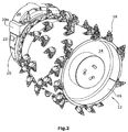
- Fig. 2 shows a perspective view of the mounted milling drum 12 with a connecting flange 14 and a bandage 16, which carries a plurality of systematically arranged tools 18.
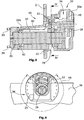
- Fig. 3 shows a section through the roller gear 10 with a gear housing 20 which can be fixed to an end wall of a roller box 2 such that a first housing part 20a is arranged with a two-stage reduction gear 24 outside of the roller box 2 and a second housing part 20b through an opening in the Front wall of the roller box 2 protrudes into the roller box 2.
- a first housing part 20a is arranged with a two-stage reduction gear 24 outside of the roller box 2 and a second housing part 20b through an opening in the Front wall of the roller box 2 protrudes into the roller box 2.
- Fig. 2 the end wall of the roller box 2 is not shown.
- a recess 28 is provided between the connecting flange 22 for attachment to the end wall of the roller box 2 and the reduction gear 24, which extends in a U-shape in the vicinity of the output shaft 26, as best of Fig. 4 is apparent.
- the recess 28 extends both below the output shaft and laterally thereof and allows the inclusion of a movable side plate 36 for lateral sealing of the roller box 2 with a complementary recess 29 adapted to the shape of the recess 28.
- the recess 28 in the lower gear housing 20 preferably comprises an in Fig. 4 apparent angular range 48 about the axis of rotation of the output shaft 26 of about 180 ° to about 300 °, preferably more than 240 °.
- oil from the lower part of the gear housing 20 can be conveyed up into a collecting trough 40, from where the oil via a channel 30 in the second housing part 20 b to a bearing 42 at the free end of the output shaft 26th can be transported.
- a space-saving and energetically neutral pump is created by a rotating in the oil sump gear 38 oil transported into the sump 40.
- the oil can pass from the sump 40 by gravity into the other housing part 20b.
- the resulting internal oil flow leads to an optimal temperature distribution of the oil in the roller gear 10.
- the oil level 34 in the transmission is indicated by a wavy line.
Landscapes
- Engineering & Computer Science (AREA)
- Mining & Mineral Resources (AREA)
- Architecture (AREA)
- Civil Engineering (AREA)
- Structural Engineering (AREA)
- Mechanical Engineering (AREA)
- General Details Of Gearings (AREA)
- Road Repair (AREA)
Description
- Die Erfindung betrifft eine Straßenfräsmaschine, insbesondere Kleinfräse, zum Bearbeiten von Straßenoberflächen nach dem Oberbegriff des Anspruchs 1.
- Eine derartige Kleinfräse ist beispielsweise unter der Bezeichnung Wirtgen W50 DC bekannt. Die grundsätzliche Konstruktion einer gattungsgemäßen Straßenfräsmaschine ist aus der
DE 196 31 042 A1 bekannt. - Die Kleinfräse weist eine an dem Maschinenrahmen in einem Walzenkasten fliegend gelagerte Fräswalze auf, die von einem Fräswalzenantrieb angetrieben werden kann.
- Der bekannte Fräswalzenantrieb weist ein Walzengetriebe auf, das teilweise im Walzenkasten angeordnet ist und teilweise außerhalb des Walzenkastens. Hierzu ist das Walzengetriebe mit Hilfe eines Anschlussflansches an einer Stirnwand des Walzenkastens befestigt.
- Bei einem bekannten Walzengetriebe gemäß
DE 10 2010 014 529 A ist zumindest ein Teil des Untersetzungsgetriebes in dem im Walzenkasten befindlichen Getriebegehäuse angeordnet, so dass die fliegend gelagerte Fräswalze das relativ zur Abtriebswelle des Walzengetriebes exzentrische Getriebegehäuse im oberen Bereich mit einem relativ kleinen Spalt umschließt. Ein derartiges, in den Walzenkasten hineinragendes Getriebegehäuse hat den Nachteil, dass in das Innere der Fräswalze eindringendes Fräsgut sich in den engen Spalt zwischen dem Getriebegehäuse und dem Innenmantel der Fräswalze festsetzt und dort zu erhöhter Reibung und Verschleiß und letztlich zu einem Leistungsverlust führt. Im Extremfall kann sich das Fräsgut in dem Spalt verkeilen und den Fräsantrieb blockieren, wodurch die Straßenfräsmaschine erheblich beschädigt werden kann.Erschwerend kommt hinzu, dass nicht nur der enge Spalt alleine, sondern die Keilform des Spaltes die Probleme erzeugt, wenn eine im Querschnitt kreisrunde Fräswalze über einen exzentrischen bzw. nicht zu der Abtriebswelle rotationssymmetrischen Getriebehals gestülpt wird. Durch die Keilform wird das Fräsgut bei ortsfestem Getriebehals und sich drehender Fräswalze in den Spalt hereingezogen und verdichtet. - Ein weiterer Nachteil des bekannten Standes der Technik besteht darin, dass dadurch, dass das Getriebegehäuse den freien Innenraum der Fräswalze nach oben fast vollständig ausnutzt, keine Fräswalzen mit einem relativ kleinen Durchmesser oder einer balligen Form eingesetzt werden können.
- Schließlich ist ein weiterer Nachteil der bekannten Konstruktionsform darin zu sehen, dass der außerhalb des Walzenkastens befindliche Gehäuseteil auf einem höheren Niveau liegt als der in dem Walzenkasten befindliche Gehäuseteil und somit zwei getrennte Ölhaushalte notwendig sind. Die getrennten Ölhaushalte erfordern zusätzliche Bauteile, wie Pumpen oder Ölkühler, und weisen mangels Temperaturausgleich zwischen den beiden Getriebeteilen Temperaturprobleme auf.
- Der Erfindung liegt daher die Aufgabe zugrunde, eine Straßenfräsmaschine, insbesondere eine Kleinfräse, der eingangs genannten Art dahingehend zu verbessern, dass die Störungsanfälligkeit des Walzengetriebes verringert wird und die Einsatzmöglichkeiten der Straßenfräsmaschine erweitert werden.
- Zur Lösung dieser Aufgabe dienen die Merkmale des Anspruchs 1.
- Die Erfindung sieht in vorteilhafter Weise vor, dass das Getriebegehäuse an der Unterseite zwischen dem Untersetzungsgetriebe und dem Anschlussflansch eine das Getriebegehäuse aufteilende, sich radial nach innen erstreckende Aussparung aufweist, derart, dass in einem außerhalb des Walzenkastens angeordneten ersten Gehäuseteil das Untersetzungsgetriebe und in einem in den Walzenkasten hineinragenden zweiten Gehäuseteil mit einer im Wesentlichen zur Abtriebsachse rotationssymmetrischen Querschnittsform die Abtriebswelle angeordnet ist.
- Die Erfindung sieht vor, dass das Untersetzungsgetriebe vollständig außerhalb des Walzenkastens angeordnet ist, so dass der in den Walzenkasten hineinragende zweite Gehäuseteil im Wesentlichen rotationssymmetrisch mit minimalem Querschnitt gestaltet werden kann. Auf diese Weise ist ein Blockieren der Fräswalze durch Fräsgut sicher ausgeschlossen, wobei außerdem auch der Verschleiß an dem Innenmantel der Fräswalze und dem zweiten Gehäuseteil minimiert wird.
- Ein weiterer Vorteil besteht darin, dass eine Vielzahl von Sonderwalzen mit reduziertem Schnittkreis, sowie Fräswalzen mit in Axialrichtung veränderlichem Durchmesser, z. B. ballige Fräswalzen, zum Einsatz kommen können. Die an der Unterseite zwischen dem Untersetzungsgetriebe und dem Anschlussflansch angeordnete vertikale Aussparung kann ein bewegliches Seitenschild aufnehmen, das das Austreten von Fräsgut aus dem Inneren des Walzenkastens bei unterschiedlichen Frästiefen des Walzenkastens weitgehend verhindern kann.
- Vorzugsweise ist vorgesehen, dass sich das Untersetzungsgetriebe vollständig im ersten Gehäuseteil befindet und, dass sich die Abtriebswelle von dem Untersetzungsgetriebe in das im Walzenkasten befindliche zweite Gehäuseteil erstreckt. Es ist somit vorgesehen, dass der im Walzenkasten befindliche Gehäuseteil nur die Abtriebswelle aufnimmt. Dadurch, dass das zweite Gehäuseteil nur die Abtriebswelle sowie die die hierzu notwendige Lagerung aufnimmt, wird der Außendurchmesser des zweiten Gehäuseteils auf einen Durchmesser reduziert, der im Wesentlichen nur durch den Außendurchmesser der Lagerung und die Wandstärke des Getriebegehäuses bestimmt wird. Insofern kann der Durchmesser des zweiten Gehäuseteils weitestgehend reduziert werden und eine im Wesentlichen rotationssymmetrische Querschnittsform annehmen.
- Vorzugsweise ist vorgesehen, dass der Abstand der Gehäusewand des in den Walzenkasten ragenden Teils des Gehäuses von der Abtriebswelle im Bereich der Aussparung auf einen die Ölzirkulation erlaubenden Spalt reduziert ist.
- Vorzugsweise ist das Getriebegehäuse an der Unterseite U-förmig ausgespart. Dies bedeutet, dass sich die sich radial nach innen erstreckende Aussparung seitlich auch neben der Abtriebswelle vertikal nach oben erstreckt. Auf diese Weise kann mit Hilfe eines Seitenschildes eine seitliche Abdichtung des Walzenkastens auch bei unterschiedlichen Frästiefen erreicht werden.
- Die U-förmige Aussparung im unteren Gehäuse umfasst einen Winkelbereich um die Rotationsachse der Abtriebswelle von beispielsweise 180° bis 300°, vorzugsweise mehr als 240°. Eine derartige Aussparung kann mit einer daran angepassten Aussparung in einer seitlichen Schutzeinrichtung, z. B. einem vertikalen Seitenschild zusammenwirken, um den Walzenkasten antriebsseitig abzudichten.
- Bei einem besonders bevorzugten Ausführungsbeispiel ist vorgesehen, dass eine Fördereinrichtung in dem ersten Gehäuseteil Öl in den oberen Bereich des Untersetzungsgetriebes befördert. Von dort kann das Öl, beispielsweise über einen Kanal in den in den Walzenkasten hineinragenden Gehäuseteil fließen, so dass eine Ölzirkulation in einem einzigen Ölhaushalt möglich ist.
- Die Fördereinrichtung kann Element des Untersetzungsgetriebes sein.
- Vorzugsweise wird hierzu ein sich im Ölsumpf drehendes Zahnrad des Untersetzungsgetriebes verwendet, um das Öl in eine Auffangwanne zu befördern, von der das Öl über mindestens einen Kanal dem nur die Abtriebswelle enthaltenden zweiten Getriebeteil zuführbar ist. Der Kanal kann dabei bis zur Lagerung der Abtriebswelle an ihrem freien Ende reichen.
- Der in den Walzenkasten ragende Teil des Gehäuses kann dabei einen Durchmesser aufweisen, der nur geringfügig größer ist als der maximale Durchmesser der Lagerung für die Antriebswelle.
- Bei einem bevorzugten Ausführungsbeispiel ist vorgesehen, dass die äußere Stirnseite der fliegend gelagerten Fräswalze nahezu bündig mit der seitlichen Außenseite des Maschinenrahmens, der sogenannten Nullseite, abschließt, um ein möglichst nahes Fräsen entlang von Hindernissen zu ermöglichen. Dabei ist der Maschinenrahmen vorzugsweise von einem Fahrwerk mit einer Vorder- und Hinterachse mit Rädern getragen, wobei die Fräswalze zwischen den Hinterrädern angeordnet ist. Diese Anordnung betrifft den Normalbetrieb der Straßenfräsmaschine, bei der beide Hinterräder koaxial und vorzugsweise in einer vertikalen Ebene mit der Fräswalzenachse angeordnet sind. Bei kantennahem Betrieb kann es sein, dass auf der Nullseite ein schwenkbares Hinterrad vorgesehen ist, das in eine Position vor die Fräswalze und relativ zur Nullseite nach innen verschwenkt werden kann. Eine derartige Anordnung ist beispielsweise auch aus der
DE 103 47 873 A1 bekannt. - Die Straßenfräsmaschine ist vorzugsweise eine Hinterladerfräsmaschine, bei der in Fahrtrichtung hinter der Fräswalze eine nach hinten abladende Transportvorrichtung für das von der Fräswalze abgearbeitete Fräsgut angeordnet ist.
- Im Folgenden wird unter Bezugnahme auf die Zeichnungen ein Ausführungsbeispiel der Erfindung näher erläutert.
- Es zeigen:
- Fig. 1
- eine Kleinfräse,
- Fig. 2
- die auf einen Fräswalzenantrieb montierte Fräswalze,
- Fig. 3
- einen Schnitt durch das Walzengetriebe, und
- Fig. 4
- einen Schnitt entlang der Linie IV-IV in
Fig. 3 . - Die in
Fig. 1 gezeigte selbstfahrende Straßenfräsmaschine 1 zum Bearbeiten von Straßenoberflächen, z. B. eine Kleinfräse, weist einen Maschinenrahmen 4 auf, sowie einen Antriebsmotor 6 für den Antrieb von Fahreinrichtungen 8 und von Arbeitseinrichtungen. Die Fahreinrichtungen 8 bestehen in dem Ausführungsbeispiel derFig. 1 aus Rädern, können aber ganz oder teilweise auch aus Kettenlaufwerken bestehen. Die hauptsächliche Arbeitseinrichtung besteht aus einer von einem Fräswalzenantrieb mit einem Walzengetriebe 10 antreibbaren Fräswalze 12 zum Fräsen der Straßenoberfläche. -
Fig. 2 zeigt eine perspektivische Ansicht der montierten Fräswalze 12 mit einem Anschlussflansch 14 und einer Bandage 16, die eine Vielzahl von systematisch angeordneten Werkzeugen 18 trägt. -
Fig. 3 zeigt einen Schnitt durch das Walzengetriebe 10 mit einem Getriebegehäuse 20, das an einer Stirnwand eines Walzenkastens 2 derart befestigt werden kann, dass ein erster Gehäuseteil 20a mit einem zweistufigen Untersetzungsgetriebe 24 außerhalb des Walzenkastens 2 angeordnet ist und ein zweiter Gehäuseteil 20b durch eine Öffnung in der Stirnwand des Walzenkastens 2 in den Walzenkasten 2 hineinragt. InFig. 2 ist die Stirnwand des Walzenkastens 2 nicht gezeigt. - An dem freien, in den Walzenkasten 2 hineinragenden Ende des Gehäuseteils 20b stehen axial Stehbolzen 39 zur Befestigung der Fräswalze 12 ab, die drehfest mit der Abtriebswelle 26 gekoppelt sind.
- An der Unterseite des Getriebegehäuses 20 ist zwischen dem Anschlussflansch 22 zur Befestigung an der Stirnwand des Walzenkastens 2 und dem Untersetzungsgetriebe 24 eine Aussparung 28 vorgesehen, die sich U-förmig im Umfeld der Abtriebswelle 26 erstreckt, wie am besten aus
Fig. 4 ersichtlich ist. - Die Aussparung 28 erstreckt sich sowohl unterhalb der Abtriebswelle als auch seitlich davon und ermöglicht die Aufnahme eines beweglichen Seitenschildes 36 zur seitlichen Abdichtung des Walzenkastens 2 mit einer der Form der Aussparung 28 angepassten komplementären Aussparung 29.
- Die Aussparung 28 im unteren Getriebegehäuse 20 umfasst vorzugsweise einen in
Fig. 4 ersichtlichen Winkelbereich 48 um die Rotationsachse der Abtriebswelle 26 von ca. 180° bis ca. 300°, vorzugsweise mehr als 240°. - Mit Hilfe eines Zahnrades 38 des Untersetzungsgetriebes 24 kann Öl aus dem unteren Teil des Getriebegehäuses 20 nach oben in eine Auffangwanne 40 gefördert werden, von wo das Öl über einen Kanal 30 in den zweiten Gehäuseteil 20b bis zu einer Lagerung 42 am freien Ende der Abtriebswelle 26 transportiert werden kann. Auf diese Weise ist eine bauraumsparende und energetisch neutrale Pumpe geschaffen, indem ein sich im Ölsumpf drehendes Zahnrad 38 Öl in die Auffangwanne 40 befördert. Das Öl kann von der Auffangwanne 40 durch Schwerkraft in den anderen Gehäuseteil 20b gelangen. Der dadurch erzeugte interne Ölstrom führt zu einer optimalen Temperaturverteilung des Öls im Walzengetriebe 10. Der Ölstand 34 im Getriebe ist durch eine gewellte Linie angezeigt.
Claims (14)
- Straßenfräsmaschine, insbesondere Kleinfräse (1), zum Bearbeiten von Straßenoberflächen, mit einem Maschinenrahmen (4),- mit einer an dem Maschinenrahmen (4) in einem Walzenkasten (2) gelagerten Fräswalze (12),- mit einem Fräswalzenantrieb mit einem an dem Walzenkasten (2) befestigten Walzengetriebe (10),- wobei das Walzengetriebe (10) ein Getriebegehäuse (20) mit einem Anschlussflansch (22) zum Befestigen an dem Walzenkasten (2), sowie ein Untersetzungsgetriebe (24) und eine Abtriebswelle (26) für den Antrieb der Fräswalze (12) aufweist,
dadurch gekennzeichnet,
dass das Getriebegehäuse (20) an der Unterseite zwischen dem Untersetzungsgetriebe (24) und dem Anschlussflansch (22) eine das Getriebegehäuse (20) aufteilende, sich radial nach innen erstreckende Aussparung (28) aufweist, derart, dass in einem außerhalb des Walzenkastens (2) angeordneten ersten Gehäuseteil (20a) das Untersetzungsgetriebe (24) und in einem in den Walzenkasten (2) hineinragenden zweiten Gehäuseteil (20b) mit im Wesentlichen zur Abtriebswelle (26) rotationssymmetrischer Querschnittsform die Abtriebswelle (26) angeordnet ist. - Straßenfräsmaschine nach Anspruch 1, dadurch gekennzeichnet,, dass sich das Untersetzungsgetriebe (24) vollständig im ersten Gehäuseteil (20a) befindet und, dass sich die Abtriebswelle (26) von dem Untersetzungsgetriebe (24) in das im Walzenkasten (2) befindliche zweite Gehäuseteil (20b) erstreckt.
- Straßenfräsmaschine nach Anspruch 1 oder 2, dadurch gekennzeichnet, dass der Abstand der Gehäusewand des Getriebegehäuses (20) von der Abtriebswelle (26) im Bereich der Aussparung (28) auf einen die Ölzirkulation zulassenden Spalt reduziert ist.
- Straßenfräsmaschine nach einem der Ansprüche 1 bis 3, dadurch gekennzeichnet, dass das Getriebegehäuse (20) an der Unterseite U-förmig ausgespart ist.
- Straßenfräsmaschine nach einem der Ansprüche 1 bis 4, dadurch gekennzeichnet, dass die Aussparung (28) im unteren Getriebegehäuse (20) einen Winkelbereich (48) um die Rotationsachse der Abtriebswelle (26) von 180° bis 300°, vorzugsweise mehr als 240°, umfasst.
- Straßenfräsmaschine nach einem der Ansprüche 1 bis 5, dadurch gekennzeichnet, dass eine Fördereinrichtung in dem ersten Gehäuseteil (20a) Öl in den oberen Bereich des Untersetzungsgetriebes (24) befördert.
- Straßenfräsmaschine nach Anspruch 6, dadurch gekennzeichnet, dass die Fördereinrichtung aus einem Element des Untersetzungsgetriebes (24) besteht.
- Straßenfräsmaschine nach Anspruch 6 oder 7, dadurch gekennzeichnet, dass die Fördereinrichtung das Öl in eine Auffangwanne (40) befördert, von der das Öl über mindestens einen Kanal (30) dem nur die Abtriebswelle (26) enthaltenden zweiten Getriebeteil (20b) zuführbar ist.
- Straßenfräsmaschine nach einem der Ansprüche 6 bis 8, dadurch gekennzeichnet, dass die Fördereinrichtung ein sich im Ölsumpf drehendes Zahnrad ist.
- Straßenfräsmaschine nach einem der Ansprüche 1 bis 9, dadurch gekennzeichnet, dass der in den Walzenkasten (2) ragende Gehäuseteil (20b) einen Durchmesser aufweist, der geringfügig größer als der Durchmesser der Lagerung (42) für die Abtriebswelle (26) ist.
- Straßenfräsmaschine nach einem der Ansprüche 1 bis 10, dadurch gekennzeichnet, dass die äußere Stirnseite der Fräswalze (12) nahezu bündig mit der seitlichen Außenseite des Maschinenrahmens (4), der sogenannten Nullseite, abschließt, um ein möglichst nahes Fräsen entlang von Hindernissen zu ermöglichen.
- Straßenfräsmaschine nach einem der Ansprüche 1 bis 11, dadurch gekennzeichnet, dass der Maschinenrahmen (4) von einem Fahrwerk mit einer Vorder- und Hinterachse mit Rädern (8) oder Kettenlaufwerken getragen ist, und dass die Fräswalze (12) zwischen den Rädern oder Kettenlaufwerken der Hinterachse angeordnet ist.
- Straßenfräsmaschine nach Anspruch 8, dadurch gekennzeichnet, dass das auf der Nullseite befindliche Rad- oder Kettenlaufwerk (8) der Hinterachse von einer Außenposition, in der es sich im Wesentlichen koaxial zu dem anderen Rad- oder Kettenlaufwerk der Hinterachse befindet, in eine Innenposition vor die Fräswalze (12) und relativ zur Nullseite nach innen verschwenkbar ist.
- Straßenfräsmaschine nach einem der Ansprüche 1 bis 13, dadurch gekennzeichnet, dass in Fahrtrichtung hinter der Fräswalze (12) eine nach hinten abladende Transportvorrichtung für das von der Fräswalze (12) abgearbeitete Fräsgut angeordnet ist.
Applications Claiming Priority (1)
| Application Number | Priority Date | Filing Date | Title |
|---|---|---|---|
| DE102013208645.8A DE102013208645B4 (de) | 2013-05-10 | 2013-05-10 | Vorrichtung, insbesondere Kleinfräse, zum Bearbeiten von Straßenoberflächen |
Publications (2)
| Publication Number | Publication Date |
|---|---|
| EP2801666A1 EP2801666A1 (de) | 2014-11-12 |
| EP2801666B1 true EP2801666B1 (de) | 2016-09-21 |
Family
ID=50628670
Family Applications (1)
| Application Number | Title | Priority Date | Filing Date |
|---|---|---|---|
| EP14166744.4A Active EP2801666B1 (de) | 2013-05-10 | 2014-04-30 | Strassenfräsmaschine, insbesondere Kleinfräse, zum Bearbeiten von Strassenoberflächen |
Country Status (4)
| Country | Link |
|---|---|
| US (1) | US9249545B2 (de) |
| EP (1) | EP2801666B1 (de) |
| CN (2) | CN104141279B (de) |
| DE (1) | DE102013208645B4 (de) |
Families Citing this family (4)
| Publication number | Priority date | Publication date | Assignee | Title |
|---|---|---|---|---|
| DE102013208645B4 (de) * | 2013-05-10 | 2018-01-11 | Wirtgen Gmbh | Vorrichtung, insbesondere Kleinfräse, zum Bearbeiten von Straßenoberflächen |
| US10584450B2 (en) * | 2017-03-23 | 2020-03-10 | Caterpillar Paving Products Inc. | Rotary mixer |
| CN107165034A (zh) * | 2017-07-18 | 2017-09-15 | 湖南煜欣轨道装备科技工程有限公司 | 一种铣刨机 |
| CN108797229A (zh) * | 2018-08-01 | 2018-11-13 | 赵茂勋 | 一种铁路混凝土层的掏挖机构 |
Family Cites Families (15)
| Publication number | Priority date | Publication date | Assignee | Title |
|---|---|---|---|---|
| US1541499A (en) * | 1923-07-10 | 1925-06-09 | Hinnekens Florent | Reduction-gear unit |
| US3608968A (en) * | 1969-04-03 | 1971-09-28 | Christensen Diamond Prod Co | Pavement cutting and water and cutting pickup apparatus |
| DE3510596A1 (de) * | 1985-03-23 | 1986-09-25 | Marks GmbH, 4350 Recklinghausen | Strassenfraese |
| US5259692A (en) * | 1992-09-04 | 1993-11-09 | Beller Larry D | Ground breaking apparatus |
| US5474397A (en) * | 1994-05-31 | 1995-12-12 | Ingersoll-Rand Company | Drum access mechanism |
| DE19631042C5 (de) | 1996-08-01 | 2015-08-20 | Wirtgen Gmbh | Straßenbaumaschinen zum Bearbeiten von Fahrbahnen |
| WO2004005623A1 (de) * | 2002-07-09 | 2004-01-15 | Wirtgen Gmbh | Selbstfahrende strassenfräsmaschine |
| DE10247579B3 (de) * | 2002-10-11 | 2004-04-15 | Wirtgen Gmbh | Abstreifeinrichtung für Fräswalzen einer Baumaschine, sowie Verfahren |
| DE10347873B4 (de) * | 2003-10-10 | 2005-08-04 | Wirtgen Gmbh | Straßenfräsmaschine mit Lenkeinrichtung |
| DE102005058102B3 (de) * | 2005-12-05 | 2007-03-01 | Wirtgen Gmbh | Abstreifeinrichtung für Fräswalzen einer Baumaschine |
| US20080205983A1 (en) * | 2007-02-22 | 2008-08-28 | Diamond Surface, Inc. | Slot cutting apparatus |
| DE102010014529A1 (de) * | 2010-04-10 | 2011-10-13 | Bomag Gmbh | Baumaschine zum Bearbeiten einer Fahrbahnoberfläche |
| DE102011009093A1 (de) * | 2010-04-17 | 2011-10-20 | Bomag Gmbh | Rotorkasten für eine Bodenmaschine und Bodenmaschine mit einem solchen Rotorkasten |
| DE102010051551A1 (de) * | 2010-11-18 | 2012-05-24 | Wirtgen Gmbh | Bodenbearbeitungsmaschine sowie Verfahren zum Fräsen von Böden oder Verkehrsflächen |
| DE102013208645B4 (de) * | 2013-05-10 | 2018-01-11 | Wirtgen Gmbh | Vorrichtung, insbesondere Kleinfräse, zum Bearbeiten von Straßenoberflächen |
-
2013
- 2013-05-10 DE DE102013208645.8A patent/DE102013208645B4/de active Active
-
2014
- 2014-04-30 EP EP14166744.4A patent/EP2801666B1/de active Active
- 2014-05-02 US US14/268,510 patent/US9249545B2/en active Active
- 2014-05-08 CN CN201410194238.2A patent/CN104141279B/zh active Active
- 2014-05-08 CN CN201420235201.5U patent/CN204185752U/zh not_active Withdrawn - After Issue
Also Published As
| Publication number | Publication date |
|---|---|
| US9249545B2 (en) | 2016-02-02 |
| CN204185752U (zh) | 2015-03-04 |
| CN104141279B (zh) | 2016-06-22 |
| US20140333117A1 (en) | 2014-11-13 |
| CN104141279A (zh) | 2014-11-12 |
| DE102013208645A1 (de) | 2014-11-13 |
| DE102013208645B4 (de) | 2018-01-11 |
| EP2801666A1 (de) | 2014-11-12 |
Similar Documents
| Publication | Publication Date | Title |
|---|---|---|
| EP2823102B1 (de) | Selbstfahrende strassenfräsmaschine zum bearbeiten von strassenoberflächen, sowie verfahren zum bearbeiten von strassenoberflächen | |
| EP2374937B1 (de) | Baumaschine zum Bearbeiten einer Fahrbahnoberfläche | |
| EP1520076B1 (de) | Selbstfahrende strassenfräsmaschine | |
| EP2740846B1 (de) | Verdichtungsmaschine | |
| EP2801666B1 (de) | Strassenfräsmaschine, insbesondere Kleinfräse, zum Bearbeiten von Strassenoberflächen | |
| EP2661947B1 (de) | Lageranordnung eines landwirtschaftlichen Geräts | |
| DE102012024770B4 (de) | Selbstfahrende Baumaschine | |
| DE102013020679A1 (de) | Rotorschwenkarm für eine Bodenfräsmaschine, Bodenfräsmaschine mit einem solchen Rotorschwenkarm | |
| DE102015209740A1 (de) | Selbstfahrende Strassenfräsmaschine zum Bearbeiten von Strassenoberflächen, sowie Verfahren zum Bearbeiten von Strassenoberflächen mit einer Strassenfräsmaschine | |
| DE102011108016A1 (de) | Selbstfahrender Oberflächenfräser | |
| EP1666671B1 (de) | Schlitzwandfräse | |
| DE102011118791B4 (de) | Förderband zur Verwendung in einer Fräsvorrichtung und Fräsvorrichtung mit einem solchen Förderband | |
| DE102009053572B4 (de) | Heckanbaugerät für eine Pistenraupe | |
| DE102010016606A1 (de) | Schleifmaschine | |
| DE102014015584B4 (de) | Fräswalze und Bodenfräsmaschine mit derartiger Fräswalze | |
| WO2015121292A1 (de) | Breitenverstellbares schwerlastfahrzeug | |
| DE102013003864A1 (de) | Straßenbaumaschine zum Bearbeiten von Straßenbelägen, insbesondere Straßenfräse | |
| EP3335846B1 (de) | Werkzeugmaschine zur kantenbearbeitung eines werkstücks | |
| DE102014014704A1 (de) | Bodenfräsmaschine und Verfahren zum Verschwenken einer Fahreinrichtung einer Bodenfräsmaschine | |
| DE10232489A1 (de) | Selbstfahrende Straßenfräsmaschine | |
| DE102018001103A1 (de) | Einrichtung zum Verzahnen von Werkstücken | |
| DE10124084B4 (de) | Bohrkopf für eine Maschine zum Bearbeiten von Tafeln aus Holz oder dergleichen | |
| DE102017204956B4 (de) | Einstellbare, austauschbare Gleiskettenmontage für einen Traktor | |
| DE102010051192A1 (de) | Fördervorrichtung, Antrieb und Herstellverfahren für eine Fördervorrichtung | |
| CH692139A5 (de) | Fahrbares Oberflächenbearbeitungsgerät. |
Legal Events
| Date | Code | Title | Description |
|---|---|---|---|
| PUAI | Public reference made under article 153(3) epc to a published international application that has entered the european phase |
Free format text: ORIGINAL CODE: 0009012 |
|
| 17P | Request for examination filed |
Effective date: 20140430 |
|
| AK | Designated contracting states |
Kind code of ref document: A1 Designated state(s): AL AT BE BG CH CY CZ DE DK EE ES FI FR GB GR HR HU IE IS IT LI LT LU LV MC MK MT NL NO PL PT RO RS SE SI SK SM TR |
|
| AX | Request for extension of the european patent |
Extension state: BA ME |
|
| R17P | Request for examination filed (corrected) |
Effective date: 20150507 |
|
| RBV | Designated contracting states (corrected) |
Designated state(s): AL AT BE BG CH CY CZ DE DK EE ES FI FR GB GR HR HU IE IS IT LI LT LU LV MC MK MT NL NO PL PT RO RS SE SI SK SM TR |
|
| GRAP | Despatch of communication of intention to grant a patent |
Free format text: ORIGINAL CODE: EPIDOSNIGR1 |
|
| INTG | Intention to grant announced |
Effective date: 20160405 |
|
| GRAS | Grant fee paid |
Free format text: ORIGINAL CODE: EPIDOSNIGR3 |
|
| GRAA | (expected) grant |
Free format text: ORIGINAL CODE: 0009210 |
|
| AK | Designated contracting states |
Kind code of ref document: B1 Designated state(s): AL AT BE BG CH CY CZ DE DK EE ES FI FR GB GR HR HU IE IS IT LI LT LU LV MC MK MT NL NO PL PT RO RS SE SI SK SM TR |
|
| REG | Reference to a national code |
Ref country code: GB Ref legal event code: FG4D Free format text: NOT ENGLISH |
|
| REG | Reference to a national code |
Ref country code: CH Ref legal event code: EP |
|
| REG | Reference to a national code |
Ref country code: AT Ref legal event code: REF Ref document number: 831170 Country of ref document: AT Kind code of ref document: T Effective date: 20161015 |
|
| REG | Reference to a national code |
Ref country code: IE Ref legal event code: FG4D Free format text: LANGUAGE OF EP DOCUMENT: GERMAN |
|
| REG | Reference to a national code |
Ref country code: DE Ref legal event code: R096 Ref document number: 502014001497 Country of ref document: DE |
|
| REG | Reference to a national code |
Ref country code: SE Ref legal event code: TRGR |
|
| REG | Reference to a national code |
Ref country code: LT Ref legal event code: MG4D Ref country code: NL Ref legal event code: MP Effective date: 20160921 |
|
| PG25 | Lapsed in a contracting state [announced via postgrant information from national office to epo] |
Ref country code: FI Free format text: LAPSE BECAUSE OF FAILURE TO SUBMIT A TRANSLATION OF THE DESCRIPTION OR TO PAY THE FEE WITHIN THE PRESCRIBED TIME-LIMIT Effective date: 20160921 Ref country code: RS Free format text: LAPSE BECAUSE OF FAILURE TO SUBMIT A TRANSLATION OF THE DESCRIPTION OR TO PAY THE FEE WITHIN THE PRESCRIBED TIME-LIMIT Effective date: 20160921 Ref country code: LT Free format text: LAPSE BECAUSE OF FAILURE TO SUBMIT A TRANSLATION OF THE DESCRIPTION OR TO PAY THE FEE WITHIN THE PRESCRIBED TIME-LIMIT Effective date: 20160921 Ref country code: NO Free format text: LAPSE BECAUSE OF FAILURE TO SUBMIT A TRANSLATION OF THE DESCRIPTION OR TO PAY THE FEE WITHIN THE PRESCRIBED TIME-LIMIT Effective date: 20161221 |
|
| PG25 | Lapsed in a contracting state [announced via postgrant information from national office to epo] |
Ref country code: NL Free format text: LAPSE BECAUSE OF FAILURE TO SUBMIT A TRANSLATION OF THE DESCRIPTION OR TO PAY THE FEE WITHIN THE PRESCRIBED TIME-LIMIT Effective date: 20160921 Ref country code: GR Free format text: LAPSE BECAUSE OF FAILURE TO SUBMIT A TRANSLATION OF THE DESCRIPTION OR TO PAY THE FEE WITHIN THE PRESCRIBED TIME-LIMIT Effective date: 20161222 Ref country code: LV Free format text: LAPSE BECAUSE OF FAILURE TO SUBMIT A TRANSLATION OF THE DESCRIPTION OR TO PAY THE FEE WITHIN THE PRESCRIBED TIME-LIMIT Effective date: 20160921 |
|
| REG | Reference to a national code |
Ref country code: FR Ref legal event code: PLFP Year of fee payment: 4 |
|
| PG25 | Lapsed in a contracting state [announced via postgrant information from national office to epo] |
Ref country code: RO Free format text: LAPSE BECAUSE OF FAILURE TO SUBMIT A TRANSLATION OF THE DESCRIPTION OR TO PAY THE FEE WITHIN THE PRESCRIBED TIME-LIMIT Effective date: 20160921 Ref country code: EE Free format text: LAPSE BECAUSE OF FAILURE TO SUBMIT A TRANSLATION OF THE DESCRIPTION OR TO PAY THE FEE WITHIN THE PRESCRIBED TIME-LIMIT Effective date: 20160921 |
|
| PG25 | Lapsed in a contracting state [announced via postgrant information from national office to epo] |
Ref country code: PT Free format text: LAPSE BECAUSE OF FAILURE TO SUBMIT A TRANSLATION OF THE DESCRIPTION OR TO PAY THE FEE WITHIN THE PRESCRIBED TIME-LIMIT Effective date: 20170123 Ref country code: ES Free format text: LAPSE BECAUSE OF FAILURE TO SUBMIT A TRANSLATION OF THE DESCRIPTION OR TO PAY THE FEE WITHIN THE PRESCRIBED TIME-LIMIT Effective date: 20160921 Ref country code: IS Free format text: LAPSE BECAUSE OF FAILURE TO SUBMIT A TRANSLATION OF THE DESCRIPTION OR TO PAY THE FEE WITHIN THE PRESCRIBED TIME-LIMIT Effective date: 20170121 Ref country code: SK Free format text: LAPSE BECAUSE OF FAILURE TO SUBMIT A TRANSLATION OF THE DESCRIPTION OR TO PAY THE FEE WITHIN THE PRESCRIBED TIME-LIMIT Effective date: 20160921 Ref country code: PL Free format text: LAPSE BECAUSE OF FAILURE TO SUBMIT A TRANSLATION OF THE DESCRIPTION OR TO PAY THE FEE WITHIN THE PRESCRIBED TIME-LIMIT Effective date: 20160921 Ref country code: CZ Free format text: LAPSE BECAUSE OF FAILURE TO SUBMIT A TRANSLATION OF THE DESCRIPTION OR TO PAY THE FEE WITHIN THE PRESCRIBED TIME-LIMIT Effective date: 20160921 Ref country code: SM Free format text: LAPSE BECAUSE OF FAILURE TO SUBMIT A TRANSLATION OF THE DESCRIPTION OR TO PAY THE FEE WITHIN THE PRESCRIBED TIME-LIMIT Effective date: 20160921 Ref country code: BG Free format text: LAPSE BECAUSE OF FAILURE TO SUBMIT A TRANSLATION OF THE DESCRIPTION OR TO PAY THE FEE WITHIN THE PRESCRIBED TIME-LIMIT Effective date: 20161221 |
|
| REG | Reference to a national code |
Ref country code: DE Ref legal event code: R097 Ref document number: 502014001497 Country of ref document: DE |
|
| PLBE | No opposition filed within time limit |
Free format text: ORIGINAL CODE: 0009261 |
|
| STAA | Information on the status of an ep patent application or granted ep patent |
Free format text: STATUS: NO OPPOSITION FILED WITHIN TIME LIMIT |
|
| PG25 | Lapsed in a contracting state [announced via postgrant information from national office to epo] |
Ref country code: DK Free format text: LAPSE BECAUSE OF FAILURE TO SUBMIT A TRANSLATION OF THE DESCRIPTION OR TO PAY THE FEE WITHIN THE PRESCRIBED TIME-LIMIT Effective date: 20160921 |
|
| 26N | No opposition filed |
Effective date: 20170622 |
|
| PG25 | Lapsed in a contracting state [announced via postgrant information from national office to epo] |
Ref country code: SI Free format text: LAPSE BECAUSE OF FAILURE TO SUBMIT A TRANSLATION OF THE DESCRIPTION OR TO PAY THE FEE WITHIN THE PRESCRIBED TIME-LIMIT Effective date: 20160921 |
|
| REG | Reference to a national code |
Ref country code: CH Ref legal event code: PL |
|
| REG | Reference to a national code |
Ref country code: IE Ref legal event code: MM4A |
|
| PG25 | Lapsed in a contracting state [announced via postgrant information from national office to epo] |
Ref country code: MC Free format text: LAPSE BECAUSE OF FAILURE TO SUBMIT A TRANSLATION OF THE DESCRIPTION OR TO PAY THE FEE WITHIN THE PRESCRIBED TIME-LIMIT Effective date: 20160921 |
|
| PG25 | Lapsed in a contracting state [announced via postgrant information from national office to epo] |
Ref country code: CH Free format text: LAPSE BECAUSE OF NON-PAYMENT OF DUE FEES Effective date: 20170430 Ref country code: LU Free format text: LAPSE BECAUSE OF NON-PAYMENT OF DUE FEES Effective date: 20170430 Ref country code: LI Free format text: LAPSE BECAUSE OF NON-PAYMENT OF DUE FEES Effective date: 20170430 |
|
| REG | Reference to a national code |
Ref country code: BE Ref legal event code: MM Effective date: 20170430 |
|
| REG | Reference to a national code |
Ref country code: FR Ref legal event code: PLFP Year of fee payment: 5 |
|
| PG25 | Lapsed in a contracting state [announced via postgrant information from national office to epo] |
Ref country code: IE Free format text: LAPSE BECAUSE OF NON-PAYMENT OF DUE FEES Effective date: 20170430 |
|
| PG25 | Lapsed in a contracting state [announced via postgrant information from national office to epo] |
Ref country code: BE Free format text: LAPSE BECAUSE OF NON-PAYMENT OF DUE FEES Effective date: 20170430 |
|
| PG25 | Lapsed in a contracting state [announced via postgrant information from national office to epo] |
Ref country code: MT Free format text: LAPSE BECAUSE OF FAILURE TO SUBMIT A TRANSLATION OF THE DESCRIPTION OR TO PAY THE FEE WITHIN THE PRESCRIBED TIME-LIMIT Effective date: 20160921 |
|
| PG25 | Lapsed in a contracting state [announced via postgrant information from national office to epo] |
Ref country code: AL Free format text: LAPSE BECAUSE OF FAILURE TO SUBMIT A TRANSLATION OF THE DESCRIPTION OR TO PAY THE FEE WITHIN THE PRESCRIBED TIME-LIMIT Effective date: 20160921 |
|
| PG25 | Lapsed in a contracting state [announced via postgrant information from national office to epo] |
Ref country code: HU Free format text: LAPSE BECAUSE OF FAILURE TO SUBMIT A TRANSLATION OF THE DESCRIPTION OR TO PAY THE FEE WITHIN THE PRESCRIBED TIME-LIMIT; INVALID AB INITIO Effective date: 20140430 |
|
| PG25 | Lapsed in a contracting state [announced via postgrant information from national office to epo] |
Ref country code: CY Free format text: LAPSE BECAUSE OF FAILURE TO SUBMIT A TRANSLATION OF THE DESCRIPTION OR TO PAY THE FEE WITHIN THE PRESCRIBED TIME-LIMIT Effective date: 20160921 |
|
| PG25 | Lapsed in a contracting state [announced via postgrant information from national office to epo] |
Ref country code: MK Free format text: LAPSE BECAUSE OF FAILURE TO SUBMIT A TRANSLATION OF THE DESCRIPTION OR TO PAY THE FEE WITHIN THE PRESCRIBED TIME-LIMIT Effective date: 20160921 |
|
| PG25 | Lapsed in a contracting state [announced via postgrant information from national office to epo] |
Ref country code: TR Free format text: LAPSE BECAUSE OF FAILURE TO SUBMIT A TRANSLATION OF THE DESCRIPTION OR TO PAY THE FEE WITHIN THE PRESCRIBED TIME-LIMIT Effective date: 20160921 |
|
| PG25 | Lapsed in a contracting state [announced via postgrant information from national office to epo] |
Ref country code: HR Free format text: LAPSE BECAUSE OF FAILURE TO SUBMIT A TRANSLATION OF THE DESCRIPTION OR TO PAY THE FEE WITHIN THE PRESCRIBED TIME-LIMIT Effective date: 20160921 |
|
| REG | Reference to a national code |
Ref country code: AT Ref legal event code: MM01 Ref document number: 831170 Country of ref document: AT Kind code of ref document: T Effective date: 20190430 |
|
| PG25 | Lapsed in a contracting state [announced via postgrant information from national office to epo] |
Ref country code: AT Free format text: LAPSE BECAUSE OF NON-PAYMENT OF DUE FEES Effective date: 20190430 |
|
| P01 | Opt-out of the competence of the unified patent court (upc) registered |
Effective date: 20230525 |
|
| PGFP | Annual fee paid to national office [announced via postgrant information from national office to epo] |
Ref country code: IT Payment date: 20230428 Year of fee payment: 10 Ref country code: FR Payment date: 20230417 Year of fee payment: 10 Ref country code: DE Payment date: 20230418 Year of fee payment: 10 |
|
| PGFP | Annual fee paid to national office [announced via postgrant information from national office to epo] |
Ref country code: SE Payment date: 20230419 Year of fee payment: 10 |
|
| PGFP | Annual fee paid to national office [announced via postgrant information from national office to epo] |
Ref country code: GB Payment date: 20230420 Year of fee payment: 10 |