EP2801530A2 - Befüllungs- und Zusammenstellungsverfahren für zwei-kammer Spritzen - Google Patents
Befüllungs- und Zusammenstellungsverfahren für zwei-kammer Spritzen Download PDFInfo
- Publication number
- EP2801530A2 EP2801530A2 EP20140167423 EP14167423A EP2801530A2 EP 2801530 A2 EP2801530 A2 EP 2801530A2 EP 20140167423 EP20140167423 EP 20140167423 EP 14167423 A EP14167423 A EP 14167423A EP 2801530 A2 EP2801530 A2 EP 2801530A2
- Authority
- EP
- European Patent Office
- Prior art keywords
- cartridge
- dissolving solution
- solution
- cooling
- lyophilization
- Prior art date
- Legal status (The legal status is an assumption and is not a legal conclusion. Google has not performed a legal analysis and makes no representation as to the accuracy of the status listed.)
- Granted
Links
Images


Classifications
-
- A—HUMAN NECESSITIES
- A61—MEDICAL OR VETERINARY SCIENCE; HYGIENE
- A61M—DEVICES FOR INTRODUCING MEDIA INTO, OR ONTO, THE BODY; DEVICES FOR TRANSDUCING BODY MEDIA OR FOR TAKING MEDIA FROM THE BODY; DEVICES FOR PRODUCING OR ENDING SLEEP OR STUPOR
- A61M5/00—Devices for bringing media into the body in a subcutaneous, intra-vascular or intramuscular way; Accessories therefor, e.g. filling or cleaning devices, arm-rests
- A61M5/178—Syringes
- A61M5/24—Ampoule syringes, i.e. syringes with needle for use in combination with replaceable ampoules or carpules, e.g. automatic
- A61M5/2448—Ampoule syringes, i.e. syringes with needle for use in combination with replaceable ampoules or carpules, e.g. automatic comprising means for injection of two or more media, e.g. by mixing
-
- A—HUMAN NECESSITIES
- A61—MEDICAL OR VETERINARY SCIENCE; HYGIENE
- A61J—CONTAINERS SPECIALLY ADAPTED FOR MEDICAL OR PHARMACEUTICAL PURPOSES; DEVICES OR METHODS SPECIALLY ADAPTED FOR BRINGING PHARMACEUTICAL PRODUCTS INTO PARTICULAR PHYSICAL OR ADMINISTERING FORMS; DEVICES FOR ADMINISTERING FOOD OR MEDICINES ORALLY; BABY COMFORTERS; DEVICES FOR RECEIVING SPITTLE
- A61J1/00—Containers specially adapted for medical or pharmaceutical purposes
- A61J1/14—Details; Accessories therefor
- A61J1/20—Arrangements for transferring or mixing fluids, e.g. from vial to syringe
-
- A—HUMAN NECESSITIES
- A61—MEDICAL OR VETERINARY SCIENCE; HYGIENE
- A61L—METHODS OR APPARATUS FOR STERILISING MATERIALS OR OBJECTS IN GENERAL; DISINFECTION, STERILISATION OR DEODORISATION OF AIR; CHEMICAL ASPECTS OF BANDAGES, DRESSINGS, ABSORBENT PADS OR SURGICAL ARTICLES; MATERIALS FOR BANDAGES, DRESSINGS, ABSORBENT PADS OR SURGICAL ARTICLES
- A61L2/00—Methods or apparatus for disinfecting or sterilising materials or objects other than foodstuffs or contact lenses; Accessories therefor
- A61L2/02—Methods or apparatus for disinfecting or sterilising materials or objects other than foodstuffs or contact lenses; Accessories therefor using physical phenomena
- A61L2/04—Heat
- A61L2/06—Hot gas
- A61L2/07—Steam
-
- A—HUMAN NECESSITIES
- A61—MEDICAL OR VETERINARY SCIENCE; HYGIENE
- A61M—DEVICES FOR INTRODUCING MEDIA INTO, OR ONTO, THE BODY; DEVICES FOR TRANSDUCING BODY MEDIA OR FOR TAKING MEDIA FROM THE BODY; DEVICES FOR PRODUCING OR ENDING SLEEP OR STUPOR
- A61M5/00—Devices for bringing media into the body in a subcutaneous, intra-vascular or intramuscular way; Accessories therefor, e.g. filling or cleaning devices, arm-rests
- A61M5/001—Apparatus specially adapted for cleaning or sterilising syringes or needles
-
- A—HUMAN NECESSITIES
- A61—MEDICAL OR VETERINARY SCIENCE; HYGIENE
- A61M—DEVICES FOR INTRODUCING MEDIA INTO, OR ONTO, THE BODY; DEVICES FOR TRANSDUCING BODY MEDIA OR FOR TAKING MEDIA FROM THE BODY; DEVICES FOR PRODUCING OR ENDING SLEEP OR STUPOR
- A61M5/00—Devices for bringing media into the body in a subcutaneous, intra-vascular or intramuscular way; Accessories therefor, e.g. filling or cleaning devices, arm-rests
- A61M5/008—Racks for supporting syringes or needles
-
- A—HUMAN NECESSITIES
- A61—MEDICAL OR VETERINARY SCIENCE; HYGIENE
- A61M—DEVICES FOR INTRODUCING MEDIA INTO, OR ONTO, THE BODY; DEVICES FOR TRANSDUCING BODY MEDIA OR FOR TAKING MEDIA FROM THE BODY; DEVICES FOR PRODUCING OR ENDING SLEEP OR STUPOR
- A61M5/00—Devices for bringing media into the body in a subcutaneous, intra-vascular or intramuscular way; Accessories therefor, e.g. filling or cleaning devices, arm-rests
- A61M5/178—Syringes
- A61M5/1782—Devices aiding filling of syringes in situ
-
- B—PERFORMING OPERATIONS; TRANSPORTING
- B65—CONVEYING; PACKING; STORING; HANDLING THIN OR FILAMENTARY MATERIAL
- B65B—MACHINES, APPARATUS OR DEVICES FOR, OR METHODS OF, PACKAGING ARTICLES OR MATERIALS; UNPACKING
- B65B29/00—Packaging of materials presenting special problems
- B65B29/10—Packaging two or more different substances isolated from one another in the package but capable of being mixed without opening the package, e.g. forming packages containing a resin and hardener isolated by a frangible partition
-
- B—PERFORMING OPERATIONS; TRANSPORTING
- B65—CONVEYING; PACKING; STORING; HANDLING THIN OR FILAMENTARY MATERIAL
- B65B—MACHINES, APPARATUS OR DEVICES FOR, OR METHODS OF, PACKAGING ARTICLES OR MATERIALS; UNPACKING
- B65B3/00—Packaging plastic material, semiliquids, liquids or mixed solids and liquids, in individual containers or receptacles, e.g. bags, sacks, boxes, cartons, cans, or jars
- B65B3/003—Filling medical containers such as ampoules, vials, syringes or the like
-
- B—PERFORMING OPERATIONS; TRANSPORTING
- B65—CONVEYING; PACKING; STORING; HANDLING THIN OR FILAMENTARY MATERIAL
- B65B—MACHINES, APPARATUS OR DEVICES FOR, OR METHODS OF, PACKAGING ARTICLES OR MATERIALS; UNPACKING
- B65B3/00—Packaging plastic material, semiliquids, liquids or mixed solids and liquids, in individual containers or receptacles, e.g. bags, sacks, boxes, cartons, cans, or jars
- B65B3/02—Machines characterised by the incorporation of means for making the containers or receptacles
- B65B3/027—Making containers from separate body and end-parts
-
- B—PERFORMING OPERATIONS; TRANSPORTING
- B65—CONVEYING; PACKING; STORING; HANDLING THIN OR FILAMENTARY MATERIAL
- B65B—MACHINES, APPARATUS OR DEVICES FOR, OR METHODS OF, PACKAGING ARTICLES OR MATERIALS; UNPACKING
- B65B31/00—Packaging articles or materials under special atmospheric or gaseous conditions; Adding propellants to aerosol containers
- B65B31/02—Filling, closing, or filling and closing, containers or wrappers in chambers maintained under vacuum or superatmospheric pressure or containing a special atmosphere, e.g. of inert gas
- B65B31/025—Filling, closing, or filling and closing, containers or wrappers in chambers maintained under vacuum or superatmospheric pressure or containing a special atmosphere, e.g. of inert gas specially adapted for rigid or semi-rigid containers
- B65B31/027—Filling, closing, or filling and closing, containers or wrappers in chambers maintained under vacuum or superatmospheric pressure or containing a special atmosphere, e.g. of inert gas specially adapted for rigid or semi-rigid containers closed by a stopper
-
- B—PERFORMING OPERATIONS; TRANSPORTING
- B65—CONVEYING; PACKING; STORING; HANDLING THIN OR FILAMENTARY MATERIAL
- B65B—MACHINES, APPARATUS OR DEVICES FOR, OR METHODS OF, PACKAGING ARTICLES OR MATERIALS; UNPACKING
- B65B63/00—Auxiliary devices, not otherwise provided for, for operating on articles or materials to be packaged
- B65B63/08—Auxiliary devices, not otherwise provided for, for operating on articles or materials to be packaged for heating or cooling articles or materials to facilitate packaging
-
- B—PERFORMING OPERATIONS; TRANSPORTING
- B65—CONVEYING; PACKING; STORING; HANDLING THIN OR FILAMENTARY MATERIAL
- B65B—MACHINES, APPARATUS OR DEVICES FOR, OR METHODS OF, PACKAGING ARTICLES OR MATERIALS; UNPACKING
- B65B7/00—Closing containers or receptacles after filling
- B65B7/16—Closing semi-rigid or rigid containers or receptacles not deformed by, or not taking-up shape of, contents, e.g. boxes or cartons
- B65B7/161—Sealing filled ampoules
-
- B—PERFORMING OPERATIONS; TRANSPORTING
- B65—CONVEYING; PACKING; STORING; HANDLING THIN OR FILAMENTARY MATERIAL
- B65B—MACHINES, APPARATUS OR DEVICES FOR, OR METHODS OF, PACKAGING ARTICLES OR MATERIALS; UNPACKING
- B65B7/00—Closing containers or receptacles after filling
- B65B7/16—Closing semi-rigid or rigid containers or receptacles not deformed by, or not taking-up shape of, contents, e.g. boxes or cartons
- B65B7/28—Closing semi-rigid or rigid containers or receptacles not deformed by, or not taking-up shape of, contents, e.g. boxes or cartons by applying separate preformed closures, e.g. lids, covers
- B65B7/2821—Closing semi-rigid or rigid containers or receptacles not deformed by, or not taking-up shape of, contents, e.g. boxes or cartons by applying separate preformed closures, e.g. lids, covers applying plugs or threadless stoppers
-
- A—HUMAN NECESSITIES
- A61—MEDICAL OR VETERINARY SCIENCE; HYGIENE
- A61M—DEVICES FOR INTRODUCING MEDIA INTO, OR ONTO, THE BODY; DEVICES FOR TRANSDUCING BODY MEDIA OR FOR TAKING MEDIA FROM THE BODY; DEVICES FOR PRODUCING OR ENDING SLEEP OR STUPOR
- A61M5/00—Devices for bringing media into the body in a subcutaneous, intra-vascular or intramuscular way; Accessories therefor, e.g. filling or cleaning devices, arm-rests
- A61M5/178—Syringes
- A61M5/31—Details
- A61M2005/3114—Filling or refilling
-
- A—HUMAN NECESSITIES
- A61—MEDICAL OR VETERINARY SCIENCE; HYGIENE
- A61M—DEVICES FOR INTRODUCING MEDIA INTO, OR ONTO, THE BODY; DEVICES FOR TRANSDUCING BODY MEDIA OR FOR TAKING MEDIA FROM THE BODY; DEVICES FOR PRODUCING OR ENDING SLEEP OR STUPOR
- A61M2207/00—Methods of manufacture, assembly or production
-
- A—HUMAN NECESSITIES
- A61—MEDICAL OR VETERINARY SCIENCE; HYGIENE
- A61M—DEVICES FOR INTRODUCING MEDIA INTO, OR ONTO, THE BODY; DEVICES FOR TRANSDUCING BODY MEDIA OR FOR TAKING MEDIA FROM THE BODY; DEVICES FOR PRODUCING OR ENDING SLEEP OR STUPOR
- A61M5/00—Devices for bringing media into the body in a subcutaneous, intra-vascular or intramuscular way; Accessories therefor, e.g. filling or cleaning devices, arm-rests
- A61M5/002—Packages specially adapted therefor, e.g. for syringes or needles, kits for diabetics
-
- A—HUMAN NECESSITIES
- A61—MEDICAL OR VETERINARY SCIENCE; HYGIENE
- A61M—DEVICES FOR INTRODUCING MEDIA INTO, OR ONTO, THE BODY; DEVICES FOR TRANSDUCING BODY MEDIA OR FOR TAKING MEDIA FROM THE BODY; DEVICES FOR PRODUCING OR ENDING SLEEP OR STUPOR
- A61M5/00—Devices for bringing media into the body in a subcutaneous, intra-vascular or intramuscular way; Accessories therefor, e.g. filling or cleaning devices, arm-rests
- A61M5/178—Syringes
- A61M5/28—Syringe ampoules or carpules, i.e. ampoules or carpules provided with a needle
- A61M5/284—Syringe ampoules or carpules, i.e. ampoules or carpules provided with a needle comprising means for injection of two or more media, e.g. by mixing
-
- B—PERFORMING OPERATIONS; TRANSPORTING
- B65—CONVEYING; PACKING; STORING; HANDLING THIN OR FILAMENTARY MATERIAL
- B65B—MACHINES, APPARATUS OR DEVICES FOR, OR METHODS OF, PACKAGING ARTICLES OR MATERIALS; UNPACKING
- B65B2220/00—Specific aspects of the packaging operation
- B65B2220/14—Adding more than one type of material or article to the same package
-
- B—PERFORMING OPERATIONS; TRANSPORTING
- B65—CONVEYING; PACKING; STORING; HANDLING THIN OR FILAMENTARY MATERIAL
- B65B—MACHINES, APPARATUS OR DEVICES FOR, OR METHODS OF, PACKAGING ARTICLES OR MATERIALS; UNPACKING
- B65B2230/00—Aspects of the final package
- B65B2230/02—Containers having separate compartments isolated from one another
Definitions
- the present invention relates to a manufacturing method of two-chamber type combined container-syringe.
- a combined container-syringe where a syringe is internally filled with an injection preparation and which is designed so that immediate injection for a patient is allowed by being unpacked from a packaging material when in use has been widely adopted by medical institutions around the world, from the viewpoint of convenience, safety and preventing injection drugs from being misused.
- a plastic front assembly is fitted to a distal end portion of a glass cartridge, and a finger grip for finger hooking is fitted to a rear end portion.
- a bypass which allows the front chamber and the rear chamber to communicate with each other is molded in an approximately central portion of the cartridge having a cylindrical shape.
- the powder preparation or the lyophilized preparation filled in the inside of the front chamber is sealed in air-tight and liquid-tight manners by a front stopper and a middle stopper, and in addition, the dissolving solution to solve or to suspend the powder preparation or the lyophilized preparation filled in the inside of the rear chamber is sealed in the air-tight and liquid-tight manners by the middle stopper and an end stopper, respectively.
- the end stopper moves forward by pushing a plunger rod, which screws a female screw provided in a rear portion of the end stopper to a male screw in a distal end, toward the front of the syringe. Accordingly, the middle stopper inserted in the anterior end of the rear chamber moves forward together with the dissolving solution filled inside the rear chamber.
- the middle stopper reaches a bypass portion molded in a cartridge, the seal is released by the bypass, and thus the dissolving solution flows into the front chamber through the bypass.
- the pushing of the plunger rod is stopped.
- the injection drug is prepared.
- the front stopper is inserted into a bypass chamber provided in the inner portion of a hub luer-lock.
- a medicinal solution inside the syringe is introduced into an injection needle from an outlet hole of a cylindrical tip.
- air bubbles remaining inside the front chamber are discharged by further pushing the plunger rod, and thus the injection drug is introduced to the injection needle through the cylindrical tip of the hub luer-lock and injected to a patient.
- the packaged and sterilized glass cartridges which are put into the tub are set in filling equipment together with the tub, a lid member that seals an upper end of an opening portion of the tub is mechanically detached within the equipment, and the glass cartridges in the nest are unpacked from the tub together with the nest.
- a filling process is performed in which the end stopper is inserted into the glass cartridge supported by the holder and the nest from an upper part thereof, the middle stopper is inserted after filling the glass cartridge with the dissolving solution, and the dissolving solution is sealed inside the glass cartridge.
- the steam sterilization is performed while the glass cartridge is filled with the dissolving solution.
- each glass cartridge is filled with a main preparation lyophilized from the upper part of each glass cartridge by the same type of the filling equipment, the front stopper is inserted on the sterilized dissolving solution, and thus the main preparation is sealed inside the glass cartridge.
- the glass cartridge filled with the main preparation is loaded and the lyophilization is performed in a freeze dryer while the glass cartridge filled with the main preparation is inserted in the nest.
- a process of pushing the front stopper that has been raised in a half-plugged state from the inside of the glass cartridge into the glass cartridge is performed by lowering a shelf plate in the freeze dryer.
- the glass cartridge is in a state of being horizontally movable together with the holder in a range of the internal diameter of the through-hole of the nest. For this reason, there are advantages that it is easy to position the glass cartridge and it is possible to perform a plurality of filling the dissolving solution operations by one line along the alignment of the through-holes of the nest at a time. In other words, it is possible to perform a process from filling the glass cartridge with the dissolving solution to completing the lyophilization in one nest without the glass cartridge as a main member being removed or transferred.
- the dissolving solution filled into the glass cartridge in the filling process has to be in a bubble-free state.
- the filling equipment which can fill the dissolving solution into the glass cartridge and seal the glass cartridge packaged by the nest and the tub does not have a function to fill the glass cartridge with the dissolving solution in a bubble-free state. Therefore, a certain volume of air (air bubble) definitely remains in the upper portion of the dissolving solution sealed between the middle stopper and the end stopper inside the glass cartridge.
- the air (air bubble) is expanded at a time of steam sterilization after filling the dissolving solution into the glass cartridge and pushes the middle stopper and the end stopper. In some cases, the end stopper is pushed outside the glass cartridge and the middle stopper is moved to the position of the bypass.
- an object of the present invention is to provide a manufacturing method of two-chamber type combined container-syringe in which a dissolving solution can be easily filled in a bubble-free state.
- a manufacturing method of two-chamber type combined container-syringe includes: a dissolving solution filling process of preparing a dissolving solution-filled cartridge by inserting an end stopper into an inner side of a cartridge which extends along an axis line and has a cylindrical shape, filling a dissolving solution onto the end stopper inside the cartridge, and inserting a middle stopper into a bypass portion positioned on an upper part of the dissolving solution in the cartridge so that the bypass portion is in a communication state; and a vacuum plugging process of eliminating air bubbles from the dissolving solution in the dissolving solution-filledcartridge and sealing the dissolving solution with the middle stopper in which the air bubbles are eliminated after the dissolving solution filling process.
- the vacuum plugging process has: a first cooling processing of cooling the inside of a vacuum plugging equipment in which the dissolving solution-filled cartridge is disposed to a cooling temperature that does not freeze the dissolving solution; a first decompression processing of decreasing pressure inside the vacuum plugging equipment while the vacuum plugging equipment maintains the cooling temperature after the first cooling processing; and a middle stopper pushing processing of pushing the middle stopper downward and bringing the middle stopper into contact with the dissolving solution after the first decompression processing.
- the air dissolved in the dissolving solution is released from the dissolving solution by cooling the dissolving solution during the first cooling processing.
- a saturated solubility of the dissolving solution decreases by cooling, accordingly, the air of which the saturated solubility exceeds the saturated solubility of the dissolving solution is released to the outside of the dissolving solution from the liquid surface of the dissolving solution.
- the air dissolved in the inside of the dissolving solution is further released, and the air released from the dissolving solution passes through a bypass portion and is discharged outside of the cartridge.
- the middle stopper comes into contact with the liquid surface of the dissolving solution during the middle stopper pushing processing, and thus it is possible to fill the solution in a bubble-free state into the space between the middle stopper and the end stopper.
- the cooling temperature in the first cooling processing of the manufacturing method of two-chamber type combined container-syringe according to the present invention, it is preferable that the cooling temperature to be 0 to 10°C. In the first decompression processing, it is preferable that the pressure inside the vacuum plugging equipment to be reduced to 5 to 15 mbar.
- the vacuum plugging process further have an index temperature measurement processing of measuring the temperature of the dissolving solution in a cooling index cartridge with the same configuration as the dissolving solution-filled cartridge which is disposed in the vacuum plugging equipment and formed by the dissolving solution filling process. Furthermore, it is preferable that the first decompression processing to be performed when the temperature of the dissolving solution in the cooling index cartridge becomes the cooling temperature after the first cooling processing.
- the cooling index cartridge which has the same configuration as the dissolving solution-filled cartridge in the vacuum plugging equipment is provided, it is possible to estimate the temperature of the dissolving solution in the dissolving solution-filled cartridge by measuring the temperature of the dissolving solution in the cooling index cartridge.
- the manufacturing method of two-chamber type combined container-syringe according to the present invention further includes a steam sterilization process in order to sterilize the dissolving solution-filled cartridge from outside after the vacuum plugging process.
- the dissolving solution can be filled in a bubble-free state in the vacuum plugging process. Therefore, it is possible to prevent the end stopper or the middle stopper from moving even when the dissolving solution-filled cartridge is heated in the steam sterilization process.
- the manufacturing method of two-chamber type combined container-syringe according to the present invention further includes: a lyophilization solution filling process of preparing a lyophilization solution-f illed cartridge in which the lyophilization solution is sealed together with internal gas by the front stopper and the middle stopper, by filling the lyophilization solution on the middle stopper which is inside the dissolving solution-filled cartridge after the steam sterilization process and by inserting the front stopper above the lyophilization solution in the cartridge; and a lyophilization process of forming a lyophilized preparation from the lyophilization solution after the lyophilization solution filling process.
- the lyophilization process has: a second cooling processing of cooling the temperature inside the freeze dryer in which the lyophilization solution-filled cartridge is disposed; a second decompression processing of making the front stopper be in a half-plugged state with respect to the cartridge by reducing the pressure inside the freeze dryer to be the pressure lower than that of the internal gas, while the temperature inside the freeze dryer is cooled after the second cooling processing; and a front stopper pushing processing of pushing the front stopper downwardafter changing the lyophilization solution by being frozen in high vacuum to the lyophilized preparation by a sublimation after the second decompression processing.
- the manufacturing method of two-chamber type combined container-syringe As the pressure is reduced after cooling the inside of the freeze dryer in which the lyophilization solution-filled cartridge are aligned, a pressure difference between an atmosphere inside the freeze dryer and the internal gas inside the cartridge is generated. As this pressure difference affects the front stopper, the front stopper moves upward. As a result, the front stopper is in a half-plugged state with respect to the cartridge. Accordingly, since the inside and the outside of the cartridge become a communication state, it is possible to form the lyophilized preparation from the lyophilization solution which is lyophilized in the cooled atmosphere inside the freeze dryer. In addition, after completing the lyophilization, it is possible to retain the lyophilized preparation, which is formed by lyophilizing the lyophilization solution by pushing the front stopper into the cartridge, in a sealed state.
- the dissolving solution filling process, the vacuum plugging process, the steam sterilization process, the lyophilization solution filling process, and the lyophilization process be performed in a state where a plurality of cartridges are horizontally aligned and supported in a nest.
- the vacuum plugging process, the steam sterilization process, and the lyophilizationprocess be performed in a state where the plurality of cartridges are stowed together with the nest inside a steel tub which is formed of stainless steel and an upper part thereof is open with a box shape.
- the tub can have a function as a tub which retains the cartridge and the nest.
- the steam sterilization process is performed in a state where the opening of the steel tub is closed with a lid main body made of stainless steel and with a lid member having a filter that closes a hole portion of the lid main body.
- the steam sterilization process be performed in a state where the steel tub is disposed to incline so that an axis line of the cartridge is inclined to a vertical direction.
- a spacer is provided which abuts both a bottom surface of an inner side of the steel tub and a lower end of the plurality of cartridges.
- each upper end of the plurality of cartridges stowed in the steel tub be the same and be positioned higher than the opening edge portion of the steel tub. It is preferable that the front stopper pushing processing performed by making a horizontally extended shelf board abuts the front stopper which is in a half-plugged state with respect to each cartridge from above.
- the vacuum plugging equipment according to the present invention further includes: a cooling index cartridge that has the same configuration as the dissolving solution-filled cartridge disposed in the vacuum plugging equipment and formed by the dissolving solution filling process; and an index temperature measurement portion that measures the temperature of the dissolving solution in the cooling index cartridge.
- two-chamber type combined container-syringe (hereinafter, referred to as combined container-syringe) according to an embodiment of the present invention will be described in detail with reference to drawings.
- the manufacturing method of two-chamber type combined container-syringe according to the embodiment includes a dissolving solution filling process S1, a vacuum plugging process S2, a steam sterilization process S3, a lyophilization solution filling process S4, a lyophilization process S5 and an assembly process S6.
- the dissolving solution filling process S1 is performed by using a cartridge set for preparing syringe 10 as shown in FIG. 2 .
- the cartridge set for preparing syringe 10 is provided with a cartridge 2 disposed to be vertically extended, a holder 11, a nest 20, a plastic tub 30, and a synthetic paper filter member 40.
- the cartridge 2 has a cylindrical shape that extends along an axis line. At an intermediate part in a direction where the cartridge 2 extends, a bypass portion 2a is provided so that a part of an inner peripheral surface of the cartridge 2 is recessed to the outside in a radial direction and extends in an axial direction of the cartridge 2. Furthermore, an outer peripheral surface of the cartridge 2 has an even outer diameter.
- the bypass portion 2a of the embodiment is not protruded from the outer peripheral surface and is a so-called multi-bypass that is formed in a range of a thickness of the cartridge 2.
- ringed ribs distal end side ringed rib 2c, rear end side ringed rib 2d protruded in a ring shape to the outside in the radial direction from the outer peripheral surface of the cartridge 2 are respectively formed at both ends of the outer peripheral surf ace of the cartridge 2, that is, opening endportions of the cartridge 2.
- the holder 11 is coaxially and externally fitted to the cartridge 2.
- the holder 11 has a tapered cylindrical shape of which the diameter gradually expands as the holder 11 vertically extends downward from the upper part of the cartridge 2, that is, from the distal end side of the cartridge 2 to the rear end side.
- the holder 11 is formed of resin material having flexibility, such as polycarbonate or the like.
- An internal diameter of an upper end portion 12 of the holder 11 is the same or slightly smaller than the outer diameter of the outer peripheral surface of the cartridge 2. Accordingly, the upper end portion 12 of the holder 11 abuts the outer peripheral surface of the cartridge 2 by the holder 11's own restoring force. Inaddition, the upper endportion 12 of the holder 11 abuts the distal end side ringed rib 2c of the cartridge 2 that vertically extends, from below.
- a plurality of slits 13 that extend downward from the upper end portion 12 is formed on the holder 11 in a circumferential direction at intervals. Accordingly, the upper end portion 12 of the holder 11 is formed to easily enlarge the diameter.
- a flange portion 14 that protrudes to the outside in the radial direction in a ring shape is formed on a lower end side of the holder 11.
- An internal diameter of the flange portion 14 is set to be larger than the outer peripheral surface of the cartridge 2, that is, outer diameters of the distal end side ringed rib 2c and the rear end side ringed rib 2d.
- a lower surface of the flange portion 14, that is, a lower end surface of the holder 11 is formed in a flat shape that is perpendicular to the axis line of the cartridge 2, and in a ring shape that is centered on the axis line.
- the holder 11 is externally fitted to the cartridge 2 from the upper part of the cartridge 2 on which a washing treatment and a silicone treatment are performed. At this time, the diameter of the upper end portion 12 side of the holder 11 is expanded by the distal end side ringed rib 2c, and accordingly, the holder 11 climbs over the distal end side ringed rib 2c.
- the nest 20 has aboard shape that extends along the horizontal plane.
- a plurality of through-holes 21 that vertically penetrates is arrayed and formed on the nest 20.
- the plurality of through-holes is horizontally formed at intervals to be in a zigzag alignment in a plan view.
- An internal diameter of the through-hole 21 is large enough for the cartridge 2 to be inserted at intervals.
- the internal diameter of the through-hole 21 is set to be larger than the outer peripheral surface of the cartridge 2, that is, the outer diameter of the distal end side ringed rib 2c and the rear end side ringed rib 2d.
- the internal diameter of the through-hole 21 is set to be smaller than the outer diameter of the lower end surface of the holder 11.
- the internal diameter of the through-hole 21 is set to be the same or slightly smaller than the internal diameter of the lower end surface of the holder 11.
- a surface facing upward in the nest 20 is parallel to the horizontal plane and has an upper surface for mounting 22 where the lower end surface of the holder 11 is mounted.
- a surface facing downward in the nest 20 is parallel to the upper surface for mounting 22, and the outer edge thereof, that is, a region of the entire outer peripheral side is a supported portion 23 that is supported by the plastic tub 30 from below.
- a plurality of sleeves 24 that are formed so that edge portions of each through-hole 21 extend downward in a cylindrical shape is formed to correspond to each through-hole 21.
- An internal diameter of the sleeve 24 has a tapered shape of which the diameter is gradually reduced downward.
- the internal diameter at the lower edge is the same or slightly larger than the outer diameter of the rear end side ringed rib 2d of the cartridge 2. Accordingly, when the cartridge 2 is inserted into the through-hole 21, the rear end side ringed rib 2d of the cartridge 2 is made to be able to penetrate the lower end of the sleeve 24.
- an internal diameter of an upper end of the sleeve 24 is set to be the same as the internal diameter of the through-hole 21.
- the cartridge 2 that is externally fitted to the holder 11 is inserted into each through-hole 21 of the nest 20 downward from above.
- the lower end surface of the holder 11 is mounted on the upper surface for mounting 22 of the nest 20. Accordingly, the cartridge 2 is supported by the nest 20 via the holder 11.
- the rear end of the cartridge 2 passes through the lower end of the sleeve 24 downward from above and is positioned at a place lower than the lower end of the sleeve 24.
- the nest 20 may adopt any material if the material is plastic and has a thermal resistance and a cold resistance, such as polycarbonate, so that the material is not damaged or deformed even when the material is exposed to a severe environment, for example, when the steam sterilization is performed at a temperature about 120°C in a state where 50 to 100 cartridges 2 are suspended, or when the lyophilization is performed at an extremely low temperature. Otherwise, the through-holes 21 that have the same number as the plastic nest 20 may be penetrated on a thin metal plate made of stainless steel or the like. In this case, each of these through-holes 21 is slightly larger than the holes on the plastic plate, and may be fitted to the sleeve 24 molded to have the same internal diameter as the plastic nest 20 so as to be used as a nest 20 for reuse.
- a thermal resistance and a cold resistance such as polycarbonate
- the plastic tub 30 has a rectangular box shape that is open upward and is formed of synthetic resin, such as plastic.
- the diameter of upper portions of four sidewalls of the plastic tub 30 is enlarged by one step toward the outside of the plastic tub 30. Accordingly, a supporting portion 31 which faces upward is formed in a flat plane shape around the entire region of an inner periphery of the plastic tub 30.
- the supported portion 23 of the nest 20 abuts the supporting portion 31 from above. Accordingly, in a state where the nest 20 is stowed in the plastic tub 30, the nest 20 is supported by the supporting portion 31.
- the synthetic paper filter member 40 is a member that closes the upper portion opening of the plastic tub 30.
- a non-woven fabric, such as Tyvek, that is welded to the outer periphery of the opening of the plastic tub 30 via a heat sealing or the like can be used as the synthetic paper filter member 40. Accordingly, it is possible to perform sterilization in the plastic tub 30 and the sterility in the inner portion of the plastic tub 30 after sterilization is ensured.
- the dissolving solution filling process S1 is performed after sterilizing an outer surface of the cartridge set for preparing syringe 10 and setting the cartridge set for preparing syringe 10 to a filler.
- the synthetic paper filter member 40 of the cartridge 2 for preparing syringe set in the filler is removed in an isolator. Afterthat, the plurality of cartridges 2 supported by the nest 20 and the holder 11 are removed from the plastic tub 30 together with the nest 20.
- an end stopper 8 is inserted into the cartridge 2 from above.
- the end stopper 8 is inserted so as to be positioned at a rear end which is a lower end of the cartridge 2.
- a dissolving solution L is injected onto the end stopper 8 in the cartridge 2.
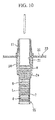
- a middle stopper 6 is inserted to a position of the bypass portion 2a which is an upper portion of the dissolving solution L in the cartridge 2 from the upper end opening of the cartridge 2. Accordingly, a space below and above the middle stopper 6 becomes a communication state via the bypass portion 2a.
- a dissolving solution-filled cartridge 15 is formed in which the end stopper 8, the dissolving solution L, and the middle stopper 6 are disposed in the order from the lower side of the cartridge 2 which vertically extends.
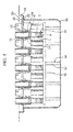
- the dissolving solution-filled cartridge 15 is stowed in a steel tub 50 in the filler in a state of being supported by the nest 20.
- the steel tub 50 has a rectangular box shape that is open upward and is formed of stainless steel.
- the diameter of upper portions of four sidewalls of the steel tub 50 is enlarged by one step toward the outside of the steel tub 50. Accordingly, a supporting portion 51 which faces upward is formed in a flat plane shape around the entire region of an inner periphery of the steel tub 50.
- the supported portion 23 of the nest 20 abuts the supporting portion 51 from above. Accordingly, in a state where the nest 20 is stowed in the steel tub 50, the nest 20 is supported by the supporting portion 51.
- the upper ends of the plurality of the dissolving solution-filled cartridges 15 supported by the nest 20, that is, all the upper ends of the cartridges 2 are positioned at the same height and positioned higher than the opening edge portion of the steel tub 50.
- the lower ends of the plurality of the dissolving solution -filled cartridges 15 supported by the nest 20, that is, all the lower ends of the cartridges 2 are positioned at the same height.
- a spacer 55 is provided which abuts both of the lower ends of the cartridges 2 and the bottom portion of an inner side of the steel tub 50.
- the spacer 55 is formed of plastic, for example.
- the spacer 55 has: aboard portion 56 which abuts the lower ends of the plurality of cartridges 2 and has a board shape; and a plurality of leg portions 57 which extends downward from the board portion 56 and abuts the bottom portion of the inner side of the steel tub 50.
- the vacuum plugging process S2 is performed in a vacuum plugging equipment 70 shown in FIG. 5 .
- the vacuum plugging equipment 70 has a chamber 71 in which the steel tub 50 stowing the cartridge 2 and the nest 20 is disposed.
- the vacuum plugging equipment 70 has: cooling means (not shown) for cooling the inside of the chamber 71, such as a cooler; decompressionmeans (not shown) for reducing a pressure of an atmosphere of the chamber 71, such as avacuumpump; and middle stopper pushing means 74.
- the vacuum plugging equipment 70 of the embodiment further has a cooling index cartridge 80 and an index temperature measurement portion 81.
- a positioning frame 72 that abuts the upper portion side surface of the steel tub 50 and a positioning base 73 that retains the bottom portion of the steel tub 50 are provided.
- the positioning frame 72 and the positioning base 73 the steel tub 50 in the chamber 71 is positioned and fixed to be immovable.
- Middle stopper pushing means 74 has a plurality of pushing rods corresponding to the upper end openings of the plurality of cartridges 2 stowed in the steel tub 50 fixed in the chamber 71, and has a configuration in which the pushing rods vertically move by oil pressure or air pressure. By descending each pushing rod that is inserted into the inner portions from the upper ends of the cartridges 2, the pushing rods push the middle stoppers 6 downward.
- the cooling index cartridge 80 has the same configuration as the dissolving solution-filled cartridge 15.
- the cooling index cartridge 80 is disposed in the chamber 71, while the steel tub 50 is disposed in the chamber 71. Accordingly, the dissolving solution-filled cartridge 15 stowed in the steel tub 50 and the cooling index cartridge 80 are exposed to the same temperature environment.
- the index temperature measurement portion 81 measures the temperature of the dissolving solution L in the cooling index cartridge 80. More specifically, the index temperature measurement portion 81 includes: a thermometer 82 that is inserted into the chamber 71 from the outside of the chamber 71, further passes through the middle stopper 6 of the cooling index cartridge 80, and can measure the temperature of the dissolving solution L; and a monitor 83 that is disposed outside of the chamber 71 and monitors the temperature measured by the thermometer 82.
- the vacuumpluggingprocess S2 includes a first cooling processing S21, an index temperature measurement processing S22, a first decompression processing S23, and a middle stopper pushing processing S24.
- the first cooling processing S21 is performed.
- the steel tub 50 is set in the chamber 71 of the vacuum plugging equipment 70.
- the steel tub 50 stowing the nest 20 and the plurality of the dissolving solution-filled cartridge 15 is set in the state in which that is positioned and fixed in the chamber 71.
- the cooling index cartridge 80 is disposed in a similar posture as the dissolving solution-filled cartridge 15 in the steel tub 50. After that, the inside of the chamber 71 becomes a sealed state.
- the temperature in the chamber 71 is cooled to the cooling temperature that does not freeze the dissolving solution L. It is preferable that the cooling temperature be in a range of 0 to 10°C, for example, and particularly, be more preferable to be set to 5°C. In this manner, the temperature of the dissolving solution L is gradually cooled by cooling the atmosphere in the chamber 71 to the cooling temperature.
- the index temperature measurement processing S22 is performed.
- the index temperature measurement processing S22 is performed in a state where the temperature in the chamber 71 is maintained at a cooling temperature.
- the temperature of the dissolving solution L in the cooling index cartridge 80 is detected via the index temperature measurement portion 81. Accordingly, the temperature of the dissolving solution L in the cooling index cartridge 80 is monitored by the monitor 83 of the index temperature measurement portion 81.
- the first decompression processing S23 is performed. If the temperature of the dissolving solution L of the cooling index cartridge 80 reaches the cooling temperature, it is estimated that the temperature of the dissolving solution L in the dissolving solution-filled cartridge 15 situated under the similar environment also decreases similarly to the cooling temperature.
- the dissolving solution L is cooled in the cooling process, and thus the air dissolved in the dissolving solution L is released from the dissolving solution L.
- the saturated solubility of the dissolving solution L decreases by cooling, accordingly, the air of which the saturated solubility exceeds the saturated solubility of the dissolving solution L is released to the outside of the dissolving solution L from the liquid surface of the dissolving solution L.
- the pressure of the atmosphere in the chamber 71 decreases by decompression means. It is preferable that the pressure in the chamber 71 decrease to 5 to 15 mbar, particularly, to 12 mbar.
- the first decompression processing S23 is also performed in a state where the cooling temperature is maintained.
- the air dissolved in the dissolving solution L is further released, and the air released from the dissolving solution L passes through the bypass portion 2a and is discharged to the outside of the cartridge 2.
- the middle stopper pushing processing S24 is performed after the first decompression processing S23.
- the middle stopper pushing processing S24 as shown in FIG. 6 , the middle stopper 6 is moved downward and comes into contact with the liquid surface of the dissolving solution L, and thus it is possible to fill the space between the middle stopper 6 and the end stopper 8 with the dissolving solution L in a bubble-free state. Accordingly, the vacuum plugging process S2 is completed.
- the middle stopper pushing processing S24 a downward load applied to the cartridge 2 via a friction between the pushed middle stopper 6 and the cartridge 2.
- the spacer 55 is interposed between the lower end of the cartridge 2 and the bottom surface of the inner side of the steel tub 50, it is possible to disperse the above-mentioned load via the spacer 55. Accordingly, it is possible to avoid an excessive load being applied to the cartridge 2.
- the steam sterilization process S3 is performed.
- a lid member 60 is attached to the steel tub 50 unpacked from the chamber 71 of the vacuum plugging equipment 70.
- the lid member 60 has a lid main body 61 and a filter 63.
- the lid main body 61 has a rectangular board shape in a plan view.
- a hole portion 62 that has a rectangular shape in a plan view is formed in the center portion of the lid main body 61.
- the filter 63 is a gas-permeable member made of non-woven fabric, synthetic paper, or the like, and is provided to close the hole portion 62 of the lid main body 61.
- the lid member 60 When an outer peripheral edge portion of the lid main body 61 comes into contact with an outer peripheral edge portion of the opening of the steel tub 50, the lid member 60 is integrated with the steel tub 50.
- a seal member for example, heat-resistant rubber or the like may be interposed at the contact portion between the lid main body 61 and the steel tub 50. In this manner, by the integration of the lid member 60 and the steel tub 50, a cartridge stowage container 65 is configured.
- the cartridge stowage container 65 is put into high-pressure steam sterilization equipment and the steam sterilization is performed. Accordingly, the steam with high temperature and high pressure passes through the filter 63, and thus the steam sterilization is performed even to the dissolving solution-filled cartridge 15 and the nest 20 in the cartridge stowage container 65.
- the lyophilization solution filling process S4 is performed in the lyophilization solution filling equipment.
- a lyophilization solution R is injected onto the middle stopper 6 in the cartridge 2 of the dissolving solution-filled cartridge 15.
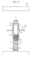
- a front stopper 5 is inserted into the upper side of the lyophilization solution R in the cartridge 2.
- a lyophilization solution-filled cartridge 16 that seals the lyophilization solution R is manufactured by the front stopper 5 and the middle stopper 6 together with an internal gas A.
- An air discharging groove 5a is formed in the front stopper 5 by being cut from a surface facing the middle stopper 6 side in the front stopper 5 along the outer peripheral surface.
- the air discharging groove 5a does not reach the upper end (distal end) of the front stopper 5. Therefore, as shown in FIG. 11 , in a state where the front stopper 5 is completely positioned in the cartridge 2, the lower part of the front stopper 5 is in a sealed state.
- the lyophilization solution filling process S4 is completed. After that, the lyophilization process S5 is performed.
- the lid member 60 Before starting the lyophilization process S5, as shown in FIG. 12 , in the lyophilization solution filling equipment, the lid member 60 is reattached to the steel tub 50 that stows the lyophilization solution-filled cartridge 16. After that, the steel tub 50 and the lid member 60 that stows the lyophilization solution-filled cartridge 16, that is, the cartridge stowage container 65 is unpacked from the lyophilization solution filling equipment and is in a standby condition until the number of the cartridge stowage container 65 applied in one lyophilization process S5 is gathered. In addition, even in the standby condition, since the lyophilization solution-filled cartridge 16 is stowed in the cartridge stowage container 65 in an aseptic condition, the sterility is not inhibited.
- the cartridge stowage container 65 is set in the freeze dryer after the lid member 60 is removed.
- the lyophilizationprocess S5 has a secondcoolingprocessing S51, a second decompression processing S52, and a front stopper pushing processing S53.
- the lyophilization solution R is frozen by cooling the temperature in the freeze dryer, that is, by cooling a shelf, on which the lyophilization solution-filled cartridges 16 are disposed on every nest 20 and every steel tub 50, and an outer atmosphere.
- the second decompression processing S52 is performed.
- the pressure of the atmosphere is reduced by reducing the pressure of the atmosphere in the freeze dryer in the second decompression processing S52.
- the pressure value of the atmosphere in the initial step becomes sufficiently lower than the pressure of the internal gas A at a space between the middle stopper 6 and the front stopper 5 in the cartridge 2. Accordingly, the pressure difference between the internal gas A and the outer atmosphere affects the front stopper 5 that is inserted into the cartridge 2, and the pressure is applied to the front stopper 5 toward the distal end side (upper side) of the cartridge 2.
- the front stopper 5 moves upward, that is, moves toward the distal end side of the cartridge 2.
- the front stopper 5 becomes a half-plugged state to the cartridge 2, and thus the pressure inside and outside of the cartridge 2 becomes an equilibrium state.
- the inside and the outside of the cartridge 2 becomes a communication state via the air discharging groove 5a in the front stopper 5. Accordingly, since the pressure applied to the front stopper 5 disappears, the movement of the front stopper 5 is stopped at the distal end of the cartridge 2.
- the inside of the freeze dryer is substituted with pure nitrogen gas until the pressure reaches to a predetermined pressure level. Accordingly, the moisture in the freeze dryer is removed, and at the same time, a descending position of the front stopper 5 is determined by the filling volume of the pure nitrogen gas and a space between the descending position and a lyophilization drug is determined in the internal space of the cartridge 2.
- the front stopper pushing processing S53 is performed.
- a shelf board 85 disposed on the upper part of the cartridge 2 in the freeze dryer moves downward while maintaining the horizontal condition. Accordingly, each shelf board 85 abuts the front stopper 5 in the plurality of cartridges 2, and the front stopper 5 is pushed into the cartridge 2.
- the front stopper 5 pushed into the cartridge 2 moves downward by the pressure difference of the inside and the outside of the cartridge 2, and finally, according to the injection volume of the nitrogen gas, as shown in FIG. 18 , the front stopper 5 is positioned at an appropriate position as a disposing position of the front stopper 5. Accordingly, a lyophilized preparation-filled cartridge 17 is formed.
- the lyophilized preparation-filled cartridge 17 formed in such a manner is unpacked together with the steel tub 50 from the freeze dryer, and the lid member 60 is reattached to the lyophilized preparation-filled cartridge 17, as shown in FIG. 19 .
- the lyophilized preparation-filled cartridge 17 is kept standby in above condition until being carried to the next assembly process S6.
- the lyophilized preparation-filled cartridge 17 is stowed in the cartridge stowage container 65 made of the steel tub 50 and the lid member 60, the sterility of the inner portion of the lyophilized preparation-filled cartridge 17 is ensured even during this standby time.
- the assembly process S6 is performed.
- a front assembly (not shown) is attached to the lyophilized preparation-filled cartridge 17 unpacked from the nest 20 together with the holder 11, and when attaching the front assembly, the holder 11 is detached from the cartridge 2.
- the combined container-syringe is completed by attaching the finger grip to the cartridge 2.
- the dissolving solution L is vacuum-filled, it is possible to easily perform the steam sterilization even after the cartridge 2 is filled with the dissolving solution L. Accordingly, it is possible to surely perform the sterilization of the dissolving solution L.
- the cooling deformation or the decompression deformation of the tub does not occur even in the steam sterilization process S3 and the lyophilization process S5 by using the steel tub 50 made of stainless steel. For this reason, through a series of processes, the tub can have a function as a tub which retains the cartridge 2 and the nest 20.
- a diameter-reducing portion at which the diameter is reduced by one step from the inner peripheral surface may be formed on the rear end (lower end) in the inner peripheral surface of the cartridge 2.
- the diameter-reducing portion regulates the movement of the end stopper 8 toward the rear end side, for example, even when the air bubbles are slightly remain in the dissolving solution L, it is possible to prevent the end stopper 8 from moving caused by expanding the air bubbles during the steam sterilization and the lyophilization.
- the configuration shown in FIGS. 20 and 21 may be modification examples of the cartridge stowage container 65.
- a rubber sealing member 66 that extends across the entire periphery of the lid main body 61 along the sealing member stowage portion 61a stowed in the sealing member stowage portion 61a in the lid mainbody 61.
- the rubber sealing member 66 is formed of, for example, a silicone rubber or the like, and is adhered to the steel tub 50 across the entire periphery in a state where the rubber sealing member 66 is stowed in the sealing member stowage portion 61a.
- roller 68 which is fixed to an arm 67 that is rotationally and movably attached around the axis line along these sides and to a distal end of the arm 67.
- the roller 68 is in a state where the lid member 60 is not fixed in a state where the roller 68 is positioned in the lower part of the lid member 60.
- the roller 68 rotationally moves on the upper part of the lid member 60, the roller 68 climbs over a protruded portion 61b provided at an outermost periphery of the lid main body 61 of the lid member 60 and is fixed to the upper surface of the lid member 60. Accordingly, the lid member 60 is integrally fixed to the steel tub 50, that is, the lid member 60 becomes a fixed condition.
- the roller 68 makes the lidmember 60 be in a fixed condition in this manner, the rubber sealing member 66 between the lid member 60 and the steel tub 50 is compressed, and thus an inner space of the cartridge stowage container 65 defined by the lid member 60 and the steel tub 50 is air-tightly isolated from outside. Therefore, it is possible to ensure the sterility of the inner space of the cartridge stowage container 65 in a simple manner. In addition, as the roller 68 rotationally moves downward, it is possible to easily detach the lid member 60 from the cartridge.
Landscapes
- Health & Medical Sciences (AREA)
- Engineering & Computer Science (AREA)
- Mechanical Engineering (AREA)
- Animal Behavior & Ethology (AREA)
- Veterinary Medicine (AREA)
- Public Health (AREA)
- General Health & Medical Sciences (AREA)
- Life Sciences & Earth Sciences (AREA)
- Heart & Thoracic Surgery (AREA)
- Hematology (AREA)
- Biomedical Technology (AREA)
- Anesthesiology (AREA)
- Vascular Medicine (AREA)
- Epidemiology (AREA)
- Chemical & Material Sciences (AREA)
- Dispersion Chemistry (AREA)
- Pharmacology & Pharmacy (AREA)
- Infusion, Injection, And Reservoir Apparatuses (AREA)
- Medical Preparation Storing Or Oral Administration Devices (AREA)
- Diabetes (AREA)
Applications Claiming Priority (1)
| Application Number | Priority Date | Filing Date | Title |
|---|---|---|---|
| JP2013098825A JP5451924B1 (ja) | 2013-05-08 | 2013-05-08 | 二室式容器兼用注射器の製造方法 |
Publications (3)
| Publication Number | Publication Date |
|---|---|
| EP2801530A2 true EP2801530A2 (de) | 2014-11-12 |
| EP2801530A3 EP2801530A3 (de) | 2015-03-11 |
| EP2801530B1 EP2801530B1 (de) | 2017-11-08 |
Family
ID=50614516
Family Applications (1)
| Application Number | Title | Priority Date | Filing Date |
|---|---|---|---|
| EP14167423.4A Active EP2801530B1 (de) | 2013-05-08 | 2014-05-07 | Befüllungs- und Zusammenstellungsverfahren für zwei-kammer Spritzen |
Country Status (3)
| Country | Link |
|---|---|
| US (1) | US9801999B2 (de) |
| EP (1) | EP2801530B1 (de) |
| JP (1) | JP5451924B1 (de) |
Cited By (1)
| Publication number | Priority date | Publication date | Assignee | Title |
|---|---|---|---|---|
| WO2019238749A1 (de) * | 2018-06-15 | 2019-12-19 | Boehringer Ingelheim International Gmbh | System, kartusche und verfahren |
Families Citing this family (9)
| Publication number | Priority date | Publication date | Assignee | Title |
|---|---|---|---|---|
| ITRM20130457A1 (it) * | 2013-08-05 | 2015-02-06 | Orofino Pharmaceuticals Group Srl | Prodotto intermedio per la realizzazione di siringhe o cartucce a doppia camera pre-riempite e procedimento di produzione di detto prodotto intermedio |
| EP3009354A1 (de) * | 2014-10-15 | 2016-04-20 | F. Hoffmann-La Roche AG | Verfahren zur Bereitstellung eines getrockneten festen Produktes in einem primären Verpackungsbehälter, das einen aktiven pharmazeutischen Inhaltsstoff enthält |
| SG11201809347XA (en) * | 2016-04-28 | 2018-11-29 | Daikyo Seiko Ltd | A container |
| EP3576809B1 (de) | 2017-02-06 | 2023-05-10 | Sanofi-Aventis Deutschland GmbH | Anordnungsnest für stiftinjektionsvorrichtung mit verriegelungsfunktion |
| WO2019189423A1 (ja) * | 2018-03-30 | 2019-10-03 | テルモ株式会社 | シリンジ収納容器及びシリンジ包装体 |
| CN108394573A (zh) * | 2018-04-18 | 2018-08-14 | 中国工程物理研究院激光聚变研究中心 | 一种原位封装装置 |
| FR3083721B1 (fr) * | 2018-07-12 | 2020-12-18 | Aptar France Sas | Dispositif de distribution de produit fluide et son procede de remplissage et de bouchage. |
| JP7292910B2 (ja) * | 2019-03-19 | 2023-06-19 | キヤノン株式会社 | 液体収納容器、液体吐出ヘッド及び液体吐出装置 |
| EP4066863A1 (de) * | 2021-03-30 | 2022-10-05 | Sartorius Biohit Liquid Handling Oy | Verpackung, verfahren und verwendung |
Citations (3)
| Publication number | Priority date | Publication date | Assignee | Title |
|---|---|---|---|---|
| JPH0446152B2 (de) | 1985-06-27 | 1992-07-29 | Duphar Int Res | |
| JP4638553B1 (ja) | 2010-08-09 | 2011-02-23 | 株式会社アルテ | 二室式容器兼用注射器の製造方法及びフロントストッパー |
| JP5081330B1 (ja) | 2012-06-20 | 2012-11-28 | 株式会社アルテ | 注射器製造用カートリッジセット及び二室式容器兼用注射器の製造方法 |
Family Cites Families (18)
| Publication number | Priority date | Publication date | Assignee | Title |
|---|---|---|---|---|
| US1305908A (en) * | 1919-06-03 | Package for ice-cream cones | ||
| DE2839219A1 (de) | 1978-09-08 | 1980-03-20 | Karl Leibinger | Sterilisierbehaelter |
| JPS5748862A (en) | 1980-09-08 | 1982-03-20 | Konishiroku Photo Ind Co Ltd | Recorder |
| US4915913A (en) * | 1984-05-22 | 1990-04-10 | Genesis Medical Corporation | Medical sterilizer device with improved latch mechanism |
| DE3613489A1 (de) * | 1986-04-22 | 1987-11-05 | Helmut Vetter | Vorrichtung zur handhabung von fertigspritzen |
| DE3900049C1 (de) * | 1989-01-03 | 1989-10-12 | Aesculap Ag, 7200 Tuttlingen, De | |
| US6413428B1 (en) * | 1999-09-16 | 2002-07-02 | Berger Instruments, Inc. | Apparatus and method for preparative supercritical fluid chromatography |
| US6629602B1 (en) | 2000-11-20 | 2003-10-07 | Becton, Dickinson And Company | Clear medical packaging |
| FR2816924B1 (fr) * | 2000-11-20 | 2003-02-14 | Becton Dickinson France | Emballage pour produits steriles |
| FR2839497B1 (fr) * | 2002-05-07 | 2005-04-15 | Becton Dickinson France | Emballage destine a etre utilise pour transporter des objets steriles ou a stereliser |
| JP2005233664A (ja) * | 2004-02-17 | 2005-09-02 | Ids:Kk | 試験管ラック |
| US20060178638A1 (en) * | 2004-12-03 | 2006-08-10 | Reynolds David L | Device and method for pharmaceutical mixing and delivery |
| US20070169434A1 (en) * | 2006-01-26 | 2007-07-26 | Shawn Kinney | Process for aseptic vacuum filling and stoppering of low viscosity liquids in syringes |
| US20090081090A1 (en) * | 2007-09-26 | 2009-03-26 | Dayman Jeffrey G | Sterilizer with modular pressure housing for a sterilization chamber |
| WO2009043000A1 (en) | 2007-09-27 | 2009-04-02 | Becton, Dickinson And Company | Cartridge for powder and liquid drug |
| JP4685198B1 (ja) * | 2010-11-11 | 2011-05-18 | 株式会社アルテ | 包装用プレート、注射器保持容器及び容器兼用注射器の製造方法 |
| US8434240B2 (en) * | 2011-01-31 | 2013-05-07 | Millrock Technology, Inc. | Freeze drying method |
| WO2013031266A1 (ja) * | 2011-08-26 | 2013-03-07 | テルモ株式会社 | シリンジ及びシリンジ収納容器 |
-
2013
- 2013-05-08 JP JP2013098825A patent/JP5451924B1/ja active Active
-
2014
- 2014-05-07 US US14/272,500 patent/US9801999B2/en active Active
- 2014-05-07 EP EP14167423.4A patent/EP2801530B1/de active Active
Patent Citations (3)
| Publication number | Priority date | Publication date | Assignee | Title |
|---|---|---|---|---|
| JPH0446152B2 (de) | 1985-06-27 | 1992-07-29 | Duphar Int Res | |
| JP4638553B1 (ja) | 2010-08-09 | 2011-02-23 | 株式会社アルテ | 二室式容器兼用注射器の製造方法及びフロントストッパー |
| JP5081330B1 (ja) | 2012-06-20 | 2012-11-28 | 株式会社アルテ | 注射器製造用カートリッジセット及び二室式容器兼用注射器の製造方法 |
Cited By (1)
| Publication number | Priority date | Publication date | Assignee | Title |
|---|---|---|---|---|
| WO2019238749A1 (de) * | 2018-06-15 | 2019-12-19 | Boehringer Ingelheim International Gmbh | System, kartusche und verfahren |
Also Published As
| Publication number | Publication date |
|---|---|
| EP2801530A3 (de) | 2015-03-11 |
| US9801999B2 (en) | 2017-10-31 |
| JP2014217578A (ja) | 2014-11-20 |
| JP5451924B1 (ja) | 2014-03-26 |
| EP2801530B1 (de) | 2017-11-08 |
| US20150013276A1 (en) | 2015-01-15 |
Similar Documents
| Publication | Publication Date | Title |
|---|---|---|
| EP2801530B1 (de) | Befüllungs- und Zusammenstellungsverfahren für zwei-kammer Spritzen | |
| JP5081330B1 (ja) | 注射器製造用カートリッジセット及び二室式容器兼用注射器の製造方法 | |
| US11786664B2 (en) | Prefilled container systems | |
| EP2812053B1 (de) | Vorrichtung zur aufnahme eines gefriergetrockneten pharmazeutischen produkts und verfahren zur herstellung eines abgedichteten behälters zur aufnahme eines gefriergetrockneten pharmazeutischen produkts | |
| EP2603189B1 (de) | Vorrichtung zur versiegelung eines gefässes und verfahren zur herstellung eines versiegelten gefässes | |
| ES2376761T3 (es) | Método para realizar un dispositivo para tratamientos oftálmicos | |
| CZ9593A3 (en) | Process of final steam sterilization | |
| EP2865400A1 (de) | Aufbewahrungsbehälter für spritzen | |
| JP2009533145A (ja) | ビンアダプターおよび圧力を調整するためのビン | |
| JP6480431B2 (ja) | 注射針保護装置 | |
| UA122170C2 (uk) | Вентильована покривна пластина для масиву шприців | |
| BR112018074925B1 (pt) | Método de empregar óxido de etileno (eto) para esterilizar uma montagem de seringa pré- preenchida | |
| PT2817240E (pt) | Unidade de acondicionamento para impedimento de ativação prematura | |
| JP2018531132A6 (ja) | カスタマイズシリンジの充填方法 | |
| JP2018531132A (ja) | カスタマイズシリンジの充填方法 |
Legal Events
| Date | Code | Title | Description |
|---|---|---|---|
| PUAI | Public reference made under article 153(3) epc to a published international application that has entered the european phase |
Free format text: ORIGINAL CODE: 0009012 |
|
| 17P | Request for examination filed |
Effective date: 20140526 |
|
| AK | Designated contracting states |
Kind code of ref document: A2 Designated state(s): AL AT BE BG CH CY CZ DE DK EE ES FI FR GB GR HR HU IE IS IT LI LT LU LV MC MK MT NL NO PL PT RO RS SE SI SK SM TR |
|
| AX | Request for extension of the european patent |
Extension state: BA ME |
|
| RIC1 | Information provided on ipc code assigned before grant |
Ipc: B65B 7/16 20060101ALI20141017BHEP Ipc: B65B 31/02 20060101ALI20141017BHEP Ipc: B65B 3/00 20060101AFI20141017BHEP Ipc: A61M 5/28 20060101ALI20141017BHEP Ipc: B65B 63/08 20060101ALI20141017BHEP Ipc: B65B 29/10 20060101ALI20141017BHEP Ipc: B65B 7/28 20060101ALI20141017BHEP Ipc: B65B 3/02 20060101ALI20141017BHEP |
|
| PUAL | Search report despatched |
Free format text: ORIGINAL CODE: 0009013 |
|
| AK | Designated contracting states |
Kind code of ref document: A3 Designated state(s): AL AT BE BG CH CY CZ DE DK EE ES FI FR GB GR HR HU IE IS IT LI LT LU LV MC MK MT NL NO PL PT RO RS SE SI SK SM TR |
|
| AX | Request for extension of the european patent |
Extension state: BA ME |
|
| RIC1 | Information provided on ipc code assigned before grant |
Ipc: A61L 2/26 20060101ALI20150130BHEP Ipc: A61M 5/00 20060101ALI20150130BHEP Ipc: B65B 3/00 20060101AFI20150130BHEP Ipc: B65B 63/08 20060101ALI20150130BHEP Ipc: A61L 2/07 20060101ALI20150130BHEP Ipc: A61M 5/28 20060101ALI20150130BHEP Ipc: B65B 31/02 20060101ALI20150130BHEP Ipc: B65B 7/28 20060101ALI20150130BHEP Ipc: B65B 29/10 20060101ALI20150130BHEP Ipc: B65B 3/02 20060101ALI20150130BHEP Ipc: A61B 19/02 20060101ALI20150130BHEP Ipc: B65B 7/16 20060101ALI20150130BHEP |
|
| RBV | Designated contracting states (corrected) |
Designated state(s): AL AT BE BG CH CY CZ DE DK EE ES FI FR GB GR HR HU IE IS IT LI LT LU LV MC MK MT NL NO PL PT RO RS SE SI SK SM TR |
|
| 17Q | First examination report despatched |
Effective date: 20160304 |
|
| GRAP | Despatch of communication of intention to grant a patent |
Free format text: ORIGINAL CODE: EPIDOSNIGR1 |
|
| RIC1 | Information provided on ipc code assigned before grant |
Ipc: B65B 7/28 20060101ALI20170616BHEP Ipc: A61M 5/00 20060101ALI20170616BHEP Ipc: B65B 29/10 20060101ALI20170616BHEP Ipc: A61L 2/07 20060101ALI20170616BHEP Ipc: B65B 7/16 20060101ALI20170616BHEP Ipc: A61L 2/26 20060101ALI20170616BHEP Ipc: A61M 5/28 20060101ALI20170616BHEP Ipc: B65B 3/00 20060101AFI20170616BHEP Ipc: B65B 63/08 20060101ALI20170616BHEP Ipc: B65B 3/02 20060101ALI20170616BHEP Ipc: B65B 31/02 20060101ALI20170616BHEP |
|
| INTG | Intention to grant announced |
Effective date: 20170712 |
|
| GRAS | Grant fee paid |
Free format text: ORIGINAL CODE: EPIDOSNIGR3 |
|
| GRAA | (expected) grant |
Free format text: ORIGINAL CODE: 0009210 |
|
| AK | Designated contracting states |
Kind code of ref document: B1 Designated state(s): AL AT BE BG CH CY CZ DE DK EE ES FI FR GB GR HR HU IE IS IT LI LT LU LV MC MK MT NL NO PL PT RO RS SE SI SK SM TR |
|
| REG | Reference to a national code |
Ref country code: GB Ref legal event code: FG4D |
|
| RIN1 | Information on inventor provided before grant (corrected) |
Inventor name: OKAJIMA, KIYOSHI Inventor name: SHIMAZAKI, SEIJI |
|
| REG | Reference to a national code |
Ref country code: CH Ref legal event code: EP Ref country code: AT Ref legal event code: REF Ref document number: 943897 Country of ref document: AT Kind code of ref document: T Effective date: 20171115 |
|
| REG | Reference to a national code |
Ref country code: IE Ref legal event code: FG4D |
|
| REG | Reference to a national code |
Ref country code: DE Ref legal event code: R096 Ref document number: 602014017093 Country of ref document: DE |
|
| REG | Reference to a national code |
Ref country code: NL Ref legal event code: FP |
|
| REG | Reference to a national code |
Ref country code: LT Ref legal event code: MG4D |
|
| REG | Reference to a national code |
Ref country code: AT Ref legal event code: MK05 Ref document number: 943897 Country of ref document: AT Kind code of ref document: T Effective date: 20171108 |
|
| PG25 | Lapsed in a contracting state [announced via postgrant information from national office to epo] |
Ref country code: NO Free format text: LAPSE BECAUSE OF FAILURE TO SUBMIT A TRANSLATION OF THE DESCRIPTION OR TO PAY THE FEE WITHIN THE PRESCRIBED TIME-LIMIT Effective date: 20180208 Ref country code: LT Free format text: LAPSE BECAUSE OF FAILURE TO SUBMIT A TRANSLATION OF THE DESCRIPTION OR TO PAY THE FEE WITHIN THE PRESCRIBED TIME-LIMIT Effective date: 20171108 Ref country code: FI Free format text: LAPSE BECAUSE OF FAILURE TO SUBMIT A TRANSLATION OF THE DESCRIPTION OR TO PAY THE FEE WITHIN THE PRESCRIBED TIME-LIMIT Effective date: 20171108 Ref country code: ES Free format text: LAPSE BECAUSE OF FAILURE TO SUBMIT A TRANSLATION OF THE DESCRIPTION OR TO PAY THE FEE WITHIN THE PRESCRIBED TIME-LIMIT Effective date: 20171108 Ref country code: SE Free format text: LAPSE BECAUSE OF FAILURE TO SUBMIT A TRANSLATION OF THE DESCRIPTION OR TO PAY THE FEE WITHIN THE PRESCRIBED TIME-LIMIT Effective date: 20171108 |
|
| REG | Reference to a national code |
Ref country code: FR Ref legal event code: PLFP Year of fee payment: 5 |
|
| PG25 | Lapsed in a contracting state [announced via postgrant information from national office to epo] |
Ref country code: RS Free format text: LAPSE BECAUSE OF FAILURE TO SUBMIT A TRANSLATION OF THE DESCRIPTION OR TO PAY THE FEE WITHIN THE PRESCRIBED TIME-LIMIT Effective date: 20171108 Ref country code: GR Free format text: LAPSE BECAUSE OF FAILURE TO SUBMIT A TRANSLATION OF THE DESCRIPTION OR TO PAY THE FEE WITHIN THE PRESCRIBED TIME-LIMIT Effective date: 20180209 Ref country code: HR Free format text: LAPSE BECAUSE OF FAILURE TO SUBMIT A TRANSLATION OF THE DESCRIPTION OR TO PAY THE FEE WITHIN THE PRESCRIBED TIME-LIMIT Effective date: 20171108 Ref country code: IS Free format text: LAPSE BECAUSE OF FAILURE TO SUBMIT A TRANSLATION OF THE DESCRIPTION OR TO PAY THE FEE WITHIN THE PRESCRIBED TIME-LIMIT Effective date: 20180308 Ref country code: BG Free format text: LAPSE BECAUSE OF FAILURE TO SUBMIT A TRANSLATION OF THE DESCRIPTION OR TO PAY THE FEE WITHIN THE PRESCRIBED TIME-LIMIT Effective date: 20180208 Ref country code: AT Free format text: LAPSE BECAUSE OF FAILURE TO SUBMIT A TRANSLATION OF THE DESCRIPTION OR TO PAY THE FEE WITHIN THE PRESCRIBED TIME-LIMIT Effective date: 20171108 Ref country code: LV Free format text: LAPSE BECAUSE OF FAILURE TO SUBMIT A TRANSLATION OF THE DESCRIPTION OR TO PAY THE FEE WITHIN THE PRESCRIBED TIME-LIMIT Effective date: 20171108 |
|
| PG25 | Lapsed in a contracting state [announced via postgrant information from national office to epo] |
Ref country code: SK Free format text: LAPSE BECAUSE OF FAILURE TO SUBMIT A TRANSLATION OF THE DESCRIPTION OR TO PAY THE FEE WITHIN THE PRESCRIBED TIME-LIMIT Effective date: 20171108 Ref country code: DK Free format text: LAPSE BECAUSE OF FAILURE TO SUBMIT A TRANSLATION OF THE DESCRIPTION OR TO PAY THE FEE WITHIN THE PRESCRIBED TIME-LIMIT Effective date: 20171108 Ref country code: CY Free format text: LAPSE BECAUSE OF FAILURE TO SUBMIT A TRANSLATION OF THE DESCRIPTION OR TO PAY THE FEE WITHIN THE PRESCRIBED TIME-LIMIT Effective date: 20171108 Ref country code: EE Free format text: LAPSE BECAUSE OF FAILURE TO SUBMIT A TRANSLATION OF THE DESCRIPTION OR TO PAY THE FEE WITHIN THE PRESCRIBED TIME-LIMIT Effective date: 20171108 Ref country code: CZ Free format text: LAPSE BECAUSE OF FAILURE TO SUBMIT A TRANSLATION OF THE DESCRIPTION OR TO PAY THE FEE WITHIN THE PRESCRIBED TIME-LIMIT Effective date: 20171108 |
|
| REG | Reference to a national code |
Ref country code: DE Ref legal event code: R097 Ref document number: 602014017093 Country of ref document: DE |
|
| PG25 | Lapsed in a contracting state [announced via postgrant information from national office to epo] |
Ref country code: RO Free format text: LAPSE BECAUSE OF FAILURE TO SUBMIT A TRANSLATION OF THE DESCRIPTION OR TO PAY THE FEE WITHIN THE PRESCRIBED TIME-LIMIT Effective date: 20171108 Ref country code: IT Free format text: LAPSE BECAUSE OF FAILURE TO SUBMIT A TRANSLATION OF THE DESCRIPTION OR TO PAY THE FEE WITHIN THE PRESCRIBED TIME-LIMIT Effective date: 20171108 Ref country code: SM Free format text: LAPSE BECAUSE OF FAILURE TO SUBMIT A TRANSLATION OF THE DESCRIPTION OR TO PAY THE FEE WITHIN THE PRESCRIBED TIME-LIMIT Effective date: 20171108 Ref country code: PL Free format text: LAPSE BECAUSE OF FAILURE TO SUBMIT A TRANSLATION OF THE DESCRIPTION OR TO PAY THE FEE WITHIN THE PRESCRIBED TIME-LIMIT Effective date: 20171108 |
|
| PLBE | No opposition filed within time limit |
Free format text: ORIGINAL CODE: 0009261 |
|
| STAA | Information on the status of an ep patent application or granted ep patent |
Free format text: STATUS: NO OPPOSITION FILED WITHIN TIME LIMIT |
|
| 26N | No opposition filed |
Effective date: 20180809 |
|
| PG25 | Lapsed in a contracting state [announced via postgrant information from national office to epo] |
Ref country code: SI Free format text: LAPSE BECAUSE OF FAILURE TO SUBMIT A TRANSLATION OF THE DESCRIPTION OR TO PAY THE FEE WITHIN THE PRESCRIBED TIME-LIMIT Effective date: 20171108 |
|
| PG25 | Lapsed in a contracting state [announced via postgrant information from national office to epo] |
Ref country code: MC Free format text: LAPSE BECAUSE OF FAILURE TO SUBMIT A TRANSLATION OF THE DESCRIPTION OR TO PAY THE FEE WITHIN THE PRESCRIBED TIME-LIMIT Effective date: 20171108 |
|
| REG | Reference to a national code |
Ref country code: IE Ref legal event code: MM4A |
|
| PG25 | Lapsed in a contracting state [announced via postgrant information from national office to epo] |
Ref country code: LU Free format text: LAPSE BECAUSE OF NON-PAYMENT OF DUE FEES Effective date: 20180507 |
|
| PG25 | Lapsed in a contracting state [announced via postgrant information from national office to epo] |
Ref country code: IE Free format text: LAPSE BECAUSE OF NON-PAYMENT OF DUE FEES Effective date: 20180507 |
|
| PG25 | Lapsed in a contracting state [announced via postgrant information from national office to epo] |
Ref country code: MT Free format text: LAPSE BECAUSE OF NON-PAYMENT OF DUE FEES Effective date: 20180507 |
|
| PG25 | Lapsed in a contracting state [announced via postgrant information from national office to epo] |
Ref country code: TR Free format text: LAPSE BECAUSE OF FAILURE TO SUBMIT A TRANSLATION OF THE DESCRIPTION OR TO PAY THE FEE WITHIN THE PRESCRIBED TIME-LIMIT Effective date: 20171108 |
|
| PG25 | Lapsed in a contracting state [announced via postgrant information from national office to epo] |
Ref country code: HU Free format text: LAPSE BECAUSE OF FAILURE TO SUBMIT A TRANSLATION OF THE DESCRIPTION OR TO PAY THE FEE WITHIN THE PRESCRIBED TIME-LIMIT; INVALID AB INITIO Effective date: 20140507 Ref country code: PT Free format text: LAPSE BECAUSE OF FAILURE TO SUBMIT A TRANSLATION OF THE DESCRIPTION OR TO PAY THE FEE WITHIN THE PRESCRIBED TIME-LIMIT Effective date: 20171108 |
|
| PG25 | Lapsed in a contracting state [announced via postgrant information from national office to epo] |
Ref country code: MK Free format text: LAPSE BECAUSE OF NON-PAYMENT OF DUE FEES Effective date: 20171108 |
|
| PG25 | Lapsed in a contracting state [announced via postgrant information from national office to epo] |
Ref country code: AL Free format text: LAPSE BECAUSE OF FAILURE TO SUBMIT A TRANSLATION OF THE DESCRIPTION OR TO PAY THE FEE WITHIN THE PRESCRIBED TIME-LIMIT Effective date: 20171108 |
|
| PGFP | Annual fee paid to national office [announced via postgrant information from national office to epo] |
Ref country code: NL Payment date: 20230526 Year of fee payment: 10 Ref country code: FR Payment date: 20230525 Year of fee payment: 10 Ref country code: DE Payment date: 20230530 Year of fee payment: 10 Ref country code: CH Payment date: 20230610 Year of fee payment: 10 |
|
| PGFP | Annual fee paid to national office [announced via postgrant information from national office to epo] |
Ref country code: BE Payment date: 20230529 Year of fee payment: 10 |
|
| PGFP | Annual fee paid to national office [announced via postgrant information from national office to epo] |
Ref country code: GB Payment date: 20230529 Year of fee payment: 10 |