EP2798657B1 - Kollisionsionengenerator und separator - Google Patents
Kollisionsionengenerator und separator Download PDFInfo
- Publication number
- EP2798657B1 EP2798657B1 EP12829144.0A EP12829144A EP2798657B1 EP 2798657 B1 EP2798657 B1 EP 2798657B1 EP 12829144 A EP12829144 A EP 12829144A EP 2798657 B1 EP2798657 B1 EP 2798657B1
- Authority
- EP
- European Patent Office
- Prior art keywords
- sample
- molecular ions
- gaseous molecular
- ions
- gaseous
- Prior art date
- Legal status (The legal status is an assumption and is not a legal conclusion. Google has not performed a legal analysis and makes no representation as to the accuracy of the status listed.)
- Active
Links
- 239000002245 particle Substances 0.000 claims description 59
- 150000001793 charged compounds Chemical class 0.000 claims description 43
- 230000007935 neutral effect Effects 0.000 claims description 34
- 239000007788 liquid Substances 0.000 claims description 32
- 238000000034 method Methods 0.000 claims description 30
- 239000000443 aerosol Substances 0.000 claims description 19
- 239000007787 solid Substances 0.000 claims description 12
- 238000010438 heat treatment Methods 0.000 claims description 10
- 238000004458 analytical method Methods 0.000 claims description 8
- 239000000126 substance Substances 0.000 claims description 4
- 239000000203 mixture Substances 0.000 claims description 3
- 150000002500 ions Chemical class 0.000 description 121
- 239000007791 liquid phase Substances 0.000 description 13
- 239000007789 gas Substances 0.000 description 12
- 238000003795 desorption Methods 0.000 description 11
- 230000015572 biosynthetic process Effects 0.000 description 10
- 230000001133 acceleration Effects 0.000 description 8
- 238000000752 ionisation method Methods 0.000 description 8
- 230000008901 benefit Effects 0.000 description 7
- 239000000470 constituent Substances 0.000 description 7
- 238000005421 electrostatic potential Methods 0.000 description 7
- 239000007921 spray Substances 0.000 description 7
- 230000003190 augmentative effect Effects 0.000 description 5
- 239000012071 phase Substances 0.000 description 5
- 238000001228 spectrum Methods 0.000 description 5
- 230000005540 biological transmission Effects 0.000 description 4
- 238000013459 approach Methods 0.000 description 3
- 230000003028 elevating effect Effects 0.000 description 3
- 238000006386 neutralization reaction Methods 0.000 description 3
- 229920001343 polytetrafluoroethylene Polymers 0.000 description 3
- 239000004810 polytetrafluoroethylene Substances 0.000 description 3
- 230000035945 sensitivity Effects 0.000 description 3
- 238000000926 separation method Methods 0.000 description 3
- 238000006243 chemical reaction Methods 0.000 description 2
- 238000013375 chromatographic separation Methods 0.000 description 2
- 238000011109 contamination Methods 0.000 description 2
- 230000007423 decrease Effects 0.000 description 2
- 238000001212 derivatisation Methods 0.000 description 2
- 238000010586 diagram Methods 0.000 description 2
- 230000000694 effects Effects 0.000 description 2
- 238000001704 evaporation Methods 0.000 description 2
- 230000008020 evaporation Effects 0.000 description 2
- 238000004949 mass spectrometry Methods 0.000 description 2
- 239000000463 material Substances 0.000 description 2
- 230000007246 mechanism Effects 0.000 description 2
- 238000012986 modification Methods 0.000 description 2
- 230000004048 modification Effects 0.000 description 2
- 230000005405 multipole Effects 0.000 description 2
- 239000002904 solvent Substances 0.000 description 2
- 238000005507 spraying Methods 0.000 description 2
- 239000013626 chemical specie Substances 0.000 description 1
- 238000004587 chromatography analysis Methods 0.000 description 1
- 150000001875 compounds Chemical class 0.000 description 1
- 239000004020 conductor Substances 0.000 description 1
- 230000003247 decreasing effect Effects 0.000 description 1
- 238000001514 detection method Methods 0.000 description 1
- 238000011161 development Methods 0.000 description 1
- 230000018109 developmental process Effects 0.000 description 1
- 238000000132 electrospray ionisation Methods 0.000 description 1
- 230000005686 electrostatic field Effects 0.000 description 1
- 230000004907 flux Effects 0.000 description 1
- 125000000524 functional group Chemical group 0.000 description 1
- 239000007792 gaseous phase Substances 0.000 description 1
- 230000002440 hepatic effect Effects 0.000 description 1
- 230000006872 improvement Effects 0.000 description 1
- 230000004941 influx Effects 0.000 description 1
- 238000011835 investigation Methods 0.000 description 1
- 238000012423 maintenance Methods 0.000 description 1
- 239000002184 metal Substances 0.000 description 1
- 102000039446 nucleic acids Human genes 0.000 description 1
- 108020004707 nucleic acids Proteins 0.000 description 1
- 150000007523 nucleic acids Chemical class 0.000 description 1
- 229920001542 oligosaccharide Polymers 0.000 description 1
- 150000002482 oligosaccharides Chemical class 0.000 description 1
- 238000005457 optimization Methods 0.000 description 1
- 230000000704 physical effect Effects 0.000 description 1
- -1 polytetrafluoroethylene Polymers 0.000 description 1
- 230000008569 process Effects 0.000 description 1
- 102000004196 processed proteins & peptides Human genes 0.000 description 1
- 108090000765 processed proteins & peptides Proteins 0.000 description 1
- 102000004169 proteins and genes Human genes 0.000 description 1
- 108090000623 proteins and genes Proteins 0.000 description 1
- 230000001105 regulatory effect Effects 0.000 description 1
- 238000012216 screening Methods 0.000 description 1
- 230000035939 shock Effects 0.000 description 1
- 239000000779 smoke Substances 0.000 description 1
- 238000004611 spectroscopical analysis Methods 0.000 description 1
- 229910001220 stainless steel Inorganic materials 0.000 description 1
- 239000010935 stainless steel Substances 0.000 description 1
- 238000013519 translation Methods 0.000 description 1
- 238000002604 ultrasonography Methods 0.000 description 1
- 239000002699 waste material Substances 0.000 description 1
Images


Classifications
-
- H—ELECTRICITY
- H01—ELECTRIC ELEMENTS
- H01J—ELECTRIC DISCHARGE TUBES OR DISCHARGE LAMPS
- H01J49/00—Particle spectrometers or separator tubes
- H01J49/02—Details
- H01J49/10—Ion sources; Ion guns
- H01J49/14—Ion sources; Ion guns using particle bombardment, e.g. ionisation chambers
- H01J49/142—Ion sources; Ion guns using particle bombardment, e.g. ionisation chambers using a solid target which is not previously vapourised
-
- H—ELECTRICITY
- H01—ELECTRIC ELEMENTS
- H01J—ELECTRIC DISCHARGE TUBES OR DISCHARGE LAMPS
- H01J49/00—Particle spectrometers or separator tubes
- H01J49/0027—Methods for using particle spectrometers
- H01J49/0031—Step by step routines describing the use of the apparatus
-
- H—ELECTRICITY
- H01—ELECTRIC ELEMENTS
- H01J—ELECTRIC DISCHARGE TUBES OR DISCHARGE LAMPS
- H01J49/00—Particle spectrometers or separator tubes
- H01J49/02—Details
- H01J49/04—Arrangements for introducing or extracting samples to be analysed, e.g. vacuum locks; Arrangements for external adjustment of electron- or ion-optical components
- H01J49/0431—Arrangements for introducing or extracting samples to be analysed, e.g. vacuum locks; Arrangements for external adjustment of electron- or ion-optical components for liquid samples
- H01J49/0445—Arrangements for introducing or extracting samples to be analysed, e.g. vacuum locks; Arrangements for external adjustment of electron- or ion-optical components for liquid samples with means for introducing as a spray, a jet or an aerosol
-
- H—ELECTRICITY
- H01—ELECTRIC ELEMENTS
- H01J—ELECTRIC DISCHARGE TUBES OR DISCHARGE LAMPS
- H01J49/00—Particle spectrometers or separator tubes
- H01J49/02—Details
- H01J49/04—Arrangements for introducing or extracting samples to be analysed, e.g. vacuum locks; Arrangements for external adjustment of electron- or ion-optical components
- H01J49/0431—Arrangements for introducing or extracting samples to be analysed, e.g. vacuum locks; Arrangements for external adjustment of electron- or ion-optical components for liquid samples
- H01J49/0454—Arrangements for introducing or extracting samples to be analysed, e.g. vacuum locks; Arrangements for external adjustment of electron- or ion-optical components for liquid samples with means for vaporising using mechanical energy, e.g. by ultrasonic vibrations
-
- H—ELECTRICITY
- H01—ELECTRIC ELEMENTS
- H01J—ELECTRIC DISCHARGE TUBES OR DISCHARGE LAMPS
- H01J49/00—Particle spectrometers or separator tubes
- H01J49/02—Details
- H01J49/10—Ion sources; Ion guns
- H01J49/14—Ion sources; Ion guns using particle bombardment, e.g. ionisation chambers
-
- H—ELECTRICITY
- H01—ELECTRIC ELEMENTS
- H01J—ELECTRIC DISCHARGE TUBES OR DISCHARGE LAMPS
- H01J49/00—Particle spectrometers or separator tubes
- H01J49/02—Details
- H01J49/10—Ion sources; Ion guns
- H01J49/16—Ion sources; Ion guns using surface ionisation, e.g. field-, thermionic- or photo-emission
Definitions
- the present invention relates to devices, systems and methods for quantifying, analyzing and/or identifying chemical species. More specifically, the present invention relates to devices, systems and methods for the conversion of certain molecular components of aerosols and liquid phase samples to gaseous molecular ions through a surface impact phenomenon which disintegrates aerosol particles or liquid jets into smaller particles including gas-phase molecular ions.
- Mass spectrometry is generally used for the investigation of the molecular composition of samples of arbitrary nature.
- the molecular constituents of samples are transferred to their gaseous phase and the individual molecules are electrically charged to yield gas-phase ions which can then be subjected to mass analysis, such as separation and selective detection of the ions based on their different mass-to-charge ratios.
- Spray ionization methods were developed as an alternative to desorption ionization techniques and were intended to address the same problems addressed by desorption ionization-the ionization of non-volatile constituents of arbitrary samples.
- liquid phase samples are sprayed using electrostatic and/or pneumatic forces.
- the resulting electrically charged droplets produced by the spraying are gradually converted to individual gas-phase ions upon the complete evaporation of the solvent.
- Spray ionization methods particularly electrospray ionization, show superior sensitivity when compared to the desorption ionization methods mentioned above as well as excellent interfacing capabilities with chromatographic techniques (something for which desorption ionization was unsuccessful).
- Nanoelectrospray, or nanospray, methods give very high ionization efficiency but are limited to extremely low flow rates; such methods can only give high ionization efficiency for flow rates in the low nanoliter per minute range. Since practical liquid chromatographic separations involve higher liquid flow rates (e.g., including high microliters per minute to low milliliters per minute), nanospray is not the usual method of choice for liquid chromatographic-mass spectrometric systems. Pneumatically assisted electrospray sources are theoretically capable of spraying liquid flow in such ranges; however their ionization efficiency falls precipitously to the 1-5% range. Similarly to desorption ionization methods, spray ionization sources also produce considerable amounts of charged and neutral clusters which decreases ionization efficiency and can tend to contaminate mass spectrometric atmospheric interfaces.
- the atmospheric interface of a mass spectrometer is designed to introduce ions formed by spray or atmospheric pressure desorption ionization to the vacuum regime of the mass spectrometer.
- the basic function of the atmospheric interface is to maximize the concentration of ions entering the mass spectrometer while reducing the amount or concentration of neutral molecules entering the mass spectrometer (e.g., air, solvent vapors, nebulae seen gases, etc.).
- the currently used approach in commercial instruments is to introduce the atmospheric gas into the mass spectrometer vacuum chamber and sample the core of the free supersonic vacuum jet using a skimmer electrode. Such an approach is based on the assumption that the ions of interest have a lower radial velocity component and will therefore be concentrated in the central core of the gas jet.
- the skimmer electrode is generally followed by radio-frequency alternating potential driven multi-pole ion guides which transmit the ionic species to the mass analyzer while the neutrals are statistically scattered and pumped out by the vacuum system.
- radio-frequency alternating potential driven multi-pole ion guides can allow up to 30% ion transmission efficiency; however, it does not solve or manage the problem of contamination by larger molecular clusters.
- Another atmospheric interface configuration includes the introduction of ion-carrying atmosphere directly into a ring electrode ion guide.
- Bipolar radiofrequency alternating current is applied to a stack of ring electrodes thereby creating a longitudinal pseudo-potential valley for charged species, while neutrals are able to leave the lens stack by passing in between the individual electrodes.
- An electrostatic potential ramp (or a traveling wave) can be used to actively accelerate ions towards the mass spectrometric analyzer.
- Such devices generally known as "ion funnels" can give close to 100% ion transmission efficiency in ion current ranges three to four orders of magnitude wide. Ion funnels have been modified in various ways to minimize the influx of neutrals and molecular clusters into the ion optics and mass analyzer.
- the simplest such solution includes the mounting of a jet-disruptor in the central axis of the funnel to block the trajectory of neutrals and molecular clusters flying through the ion funnel.
- Alternate solutions include: an asymmetric funnel geometry in which the exit orifice of the funnel is in an off-axis position relative to the atmospheric inlet; and twin-funnels in which the ion-carrying atmospheric gas is introduced into one funnel and the ions extracted sideways into a contralateral funnel, which is later connected to the ion optics of the instrument, using an electrostatic field(s).
- US 2006/108539 discloses a modified electrospray apparatus wherein changed microdroplets are caused to impact upon a heated impact plate.
- US 2003/119193 discloses a high throughput method of screening droplets.
- EP 1855306 discloses a so-called "Universal Soft Ionization Source (USIS)" combining various physical effects such as laser light, ultrasound, electrostatic potential and temperature.
- USIS Universal Soft Ionization Source
- a system for generating gaseous molecular ions for analysis by a mass spectrometer or ion mobility spectrometer includes a tubular conduit, a collision element, and an ion funnel guide assembly.
- the tubular conduit is configured to accelerate a sample therethrough.
- the sample accelerated through tubular conduit includes one of an aerosol sample and a liquid sample and has one or more of molecular particle clusters, solid particles and charged particles.
- the collision element is spaced apart from an opening of the tubular conduit and is generally aligned with an axis of the tubular conduit.
- the collision element has a generally spherical surface on which the sample collides.
- the collision between the sample and the generally spherical collision element disintegrates the one or more molecular particle clusters to form one or more gaseous molecular ions, neutral molecules and smaller-sized molecular particle clusters.
- the ion funnel guide assembly is generally aligned with the tubular conduit opening and is driven by a bipolar radiofrequency alternating current.
- the collision element is disposed in the ion funnel.
- the ion funnel guide assembly is configured to separate the gaseous molecular ions from the neutral molecules and smaller sized molecular particle clusters, and to direct the gaseous molecular ions to an analyzer.
- a system for generating gaseous molecular ions for analysis by a mass spectrometer and/or ion mobility spectrometer includes a tubular conduit, a skimmer electrode, and an analyzer unit.
- the tubular conduit is configured to accelerate a sample therethrough.
- the sample accelerated through the tubular conduit includes one of an aerosol sample and a liquid sample and has one or more of molecular particle clusters, solid particles and charged particles.
- the skimmer electrode is spaced apart from and generally aligned with an opening of the tubular conduit.
- the skimmer electrode has a tubular section with a surface upon which the sample particles collide to generate gaseous molecular ions.
- the analyzer unit which receives the gaseous molecular ions from the skimmer electrode is configured to analyze the gaseous molecular ions to provide information on the chemical composition of the sample.
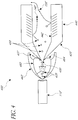
- Figure 1 is a schematic view of one embodiment of a system for surface impact ionization.
- Figure 1 illustrates one embodiment of a system for surface impact ionization 100.
- the system 100 includes a sample inlet 110, a sample 120 (e.g., a sample beam), a collision surface 130, at least one ionic species formed on the impact event 140 and other molecular neutral species 150.
- the sample 120 comprised of one or more molecular clusters, solid particles, neutral particles and charged particles (e.g., in the form of an aerosol or liquid), is introduced through the sample inlet 110 from a high pressure regime to the lower pressure regime of a mass spectrometer device. Particles of the sample 120 are accelerated by the pressure differential of the high pressure regime to low pressure regime.
- the heterogeneous or homogenous accelerated sample 120 impacts onto the collision surface 130 (e.g., a solid surface), which disintegrates the molecular clusters or continuous liquid jet of the sample 120 (see Figure 3 ) into gaseous molecular species, including individual molecular neutral species 150, and molecular ionic species 140 (e.g., gaseous molecular ions).
- the impact driven disintegration is purely mechanical, driven by the kinetic energy of the particles in the sample 120 and produces both positive and negative ions. Both the positive and negative ionic species formed on the impact event between the sample 120 and collision surface 130 are collected and transferred into the ion optics of the ion analyzer unit (see Figure IB).
- the systems and methods disclosed herein can result in improved signal to noise ratios of greater than 1%, greater than 10%, greater than 50%, greater than 100%, and greater than 200%, as well as values in between.
- the system 100 can be part of a larger ion analysis system 185 that includes a sample source 190 that provides, directs or guides samples to the system 100, (which operates as discussed with respect to Figure 1 ), and an ion analyzer 195 disposed downstream of the system 100, which receives the gaseous molecular ions from the system 100 and analyzes them to provide information on the sample's chemical constituents.
- a sample source 190 that provides, directs or guides samples to the system 100, (which operates as discussed with respect to Figure 1 )
- an ion analyzer 195 disposed downstream of the system 100, which receives the gaseous molecular ions from the system 100 and analyzes them to provide information on the sample's chemical constituents.
- the sample inlet 110 is a tubular opening at the end of a tubular conduit.
- the tubular conduit can have a round cross-section. In other embodiments, the tubular conduit can have other suitable cross-sections.
- the high pressure regime from which the sample inlet 110 introduces the sample 120 is at atmospheric pressure. In other embodiments, the high pressure regime from which the sample inlet 110 introduces the sample 120 is at a pressure higher than atmospheric pressure. In another embodiment, the high pressure regime from which the sample inlet 110 introduces the sample 120 is below atmospheric pressure (e.g., being high relative to the internal pressure of the ion analyzer device).
- the acceleration provided by the pressure differential of the high pressure regime to low pressure regime is augmented by the addition of a power source which can establish an electrical potential gradient between the sample inlet 110 and the collision surface 130 (e.g., collision element). Establishing such a potential gradient can cause or increase the acceleration of the charged particles included in the sample 120.
- a power source which can establish an electrical potential gradient between the sample inlet 110 and the collision surface 130 (e.g., collision element). Establishing such a potential gradient can cause or increase the acceleration of the charged particles included in the sample 120.
- the mechanical force based disintegration of the sample 120 and generation of molecular ionic species 140 can be augmented, or further facilitated, by elevating the temperature of the collision surface 130.
- the temperature of the collision surface 130 can be elevated via contact heating, resistive heating, or radiative heating of the collision surface 130.
- the collision surface 130 can kept at subambient temperatures. In other embodiments, the collision surface 130 can be kept at ambient or superambient temperatures (e.g., up to 1000°C or higher).
- the sample inlet 110 can be kept at subambient temperatures.
- the sample inlet 110 can be kept at ambient or superambient temperature (e.g., up to 1000°C or higher).
- a temperature difference is applied between the collision surface 130 and the other elements of the system for surface impact ionization 100 (e.g., sample inlet 110, or other surfaces).
- the collision surface 130 is at a higher temperature than the other elements of the system for surface impact ionization 100 (e.g., sample inlet 110 or other surfaces).
- the collision surface 130 is at a lower temperature than the other elements of the system for surface impact ionization 100.
- the ratio of positive and negative ions produced upon impact is shifted by applying a potential difference between the collision surface 130 and the ion optics of the mass spectrometer (such as the ion analyzer 195 in Figure IB).
- Applying a positive electrical potential on the collision surface 130 relative to the first element of the ion optics can enhance the formation of positive ions and suppress the formation of negative ions.
- applying a negative electrical potential on the collision surface 130 relative to the first element of the ion optics can enhance the formation of negative ions and suppress the formation of positive ions. Therefore, in these embodiments, when the ion of interest is a negatively charged species, it is useful to apply a negative potential between the collision surface 130 relative to the ion optics.
- the ion of interest is a positively charged species
- the application of electrostatic potential between the collision surface 130 and the ion optics can advantageously minimize the neutralization of already-existing ionic components of the sample 120.
- the collision surface 130 is placed in an ion funnel or ring electrode type ion guide, as disclosed below, which can advantageously increase collection and transmission efficiency of both the originally introduced ions and those formed on the impact event to substantially 100%.
- the collision surface 130 is substantially flat (e.g., as is depicted in Figure 1 ).
- the collision surface 130 can have other shapes (e.g., curved, spherical, teardrop, concave, dish-shaped, conical, etc.)
- the at least one ionic species formed on the impact event 140 e.g., gaseous molecular ions
- a skimmer electrode such as the skimmer electrodes disclosed herein, after colliding with the collision surface 130.
- Figure 1B illustrates a block diagram of a system for converting a liquid sample into gaseous ions and analyzing the gaseous ions 185.
- the system 185 includes a sample source 190, the surface impact ionization system 100 of Figure 1 , and an ion analyzer 195.
- the sample source 190 provides, directs or guides samples to the system 100, (which operates as discussed with respect to Figure 1 ).
- the ion analyzer 195 disposed downstream of the system 100, receives the gaseous molecular ions from the system 100 and analyzes them to provide information on the sample's chemical constituents.
- the ion analyzer 195 is a mass spectrometer.
- the ion analyzer 195 is an ion mobility spectrometer.
- the ion analyzer 195 is a combination of both a mass spectrometer and an ion mobility spectrometer.
- Figure 2 illustrates a flow chart of one embodiment of a method for preparing a sample for mass spectroscopic analysis 200.
- a sample 120 of Figure 1 is introduced from the high pressure regime of the sample inlet 110 of Figure 1 into the low pressure regime (e.g., vacuum) of the mass spectrometer.
- the low pressure regime e.g., vacuum
- the sample is an aerosol sample. In other embodiments, the sample is a liquid sample.
- step 220 the sample 120 of Figure 1 is accelerated.
- the acceleration is effected only by the passage of the sample 120 of Figure 1 from the high pressure regime of the sample inlet 110 of Figure 1 to the low pressure regime of the mass spectrometer. In some embodiments, the acceleration is augmented or caused by the application of an electrical potential gradient between the sample inlet 110 of Figure 1 and the collision surface 130 of Figure 1 to cause an acceleration of the charged particles contained in the sample 120 of Figure 1 . In yet other embodiments, the sample is accelerated by any mechanism capable of accelerating the sample to speeds high enough to cause disintegration of the sample upon impact with the collision surface 130 of Figure 1 .
- step 230 the sample collides with the collision surface 130 of Figure 1 .
- the collision of the sample 120 of Figure 1 with the collision surface 130 of Figure 1 disintegrates the sample 120 of Figure 1 into gaseous molecular species, including individual molecular neutral species 150 of Figure 1 (e.g., gaseous molecular neutrals), and molecular ionic species 140 of Figure 1 (e.g., gaseous molecular ions).
- individual molecular neutral species 150 of Figure 1 e.g., gaseous molecular neutrals
- molecular ionic species 140 of Figure 1 e.g., gaseous molecular ions
- the disintegration is due solely to mechanical forces and the release of kinetic energy. In other embodiments, the disintegration due to mechanical forces is augmented, or further facilitated, by elevating the temperature of the collision surface 130 of Figure 1 .
- the collision surface 130 can kept at subambient temperatures. In other embodiments, the collision surface 130 can be kept at ambient or superambient temperatures (e.g., up to 1000°C or higher).
- the sample inlet 110 can be kept at subambient temperatures. In other embodiments, the sample inlet 110 can be kept at ambient or superambient temperature (e.g., up to 1000°C or higher).
- a temperature difference is applied between the collision surface 130 and the other elements of the system for surface impact ionization 100 (e.g., sample inlet 110, or other surfaces). In some of these embodiments in which a temperature difference is applied, the collision surface 130 is at a higher temperature than the other elements of the system for surface impact ionization 100 (e.g., sample inlet 110 or other surfaces). In other embodiments in which a temperature difference is applied, the collision surface 130 is at a lower temperature than the other elements of the system for surface impact ionization 100. In some embodiments, the ratio of positive and negative ions produced upon impact is shifted by applying an electrical potential difference between the collision surface 130 of Figure 1 and the ion optics of the mass spectrometer.
- Placing a positive electrical potential on the collision surface 130 relative to the first element of the ion optics can enhance the formation of positive ions and suppress the formation of negative ions while placing a negative electrical potential on the collision surface 130 relative to the first element of the ion optics can enhance the formation of negative ions and suppress the formation of positive ions.
- the application of electrostatic potential between the collision surface 130 and the ion optics can have the additional advantageous effect of minimizing the neutralization of already-existing ionic components of the sample 120.
- step 250 the ions produced during the collision event are collected for transportation to the ion analyzer unit while the neutrals and other waste particles produced during the collision event can be discarded.
- step 260 the collected ions are transported to the ion analyzer unit to be read/analyzed by the mass spectrometer.
- Figure 3 illustrates another embodiment of a system for surface impact ionization 300.
- the system 300 includes a liquid sample nozzle or inlet 310, a liquid sample beam (liquid jet) 320, a collision surface 130', at least one molecular ionic species 140', and at least one molecule or other neutrals 150'.
- sample inlet 110', sample beam 120' collision surface 130', molecular ionic species 140', and molecular neutral species 150' as illustrated in this and other figures can be similar (e.g., identical) to components and elements discussed elsewhere and having the same reference number.
- the system 300 operates in a nearly identical manner to the system 100 of Figure 1 .
- the liquid jet 320 is introduced through the liquid sample nozzle 310 from a high pressure regime to the lower pressure regime of a mass spectrometer device. Particles of the liquid jet 320 are accelerated by the pressure differential of the high pressure regime to low pressure regime. After acceleration, the accelerated liquid jet 320 impacts onto the collision surface 130' which disintegrates the continuous liquid jet 320 into individual molecular neutral species 150', and molecular ionic species 140'.
- the impact driven disintegration is purely mechanical, driven by the kinetic energy of the particles in the liquid jet 320 and produces both positive and negative ions. Both the positive and negative ionic species formed on the impact event between the liquid sample beam 320 and collision surface 130' are collected and transferred into the ion optics of the ion analyzer unit.
- the mechanical force based disintegration of the liquid jet 320 can be augmented, or further facilitated, by elevating the temperature of the collision surface 130'.
- the temperature of the collision surface 130' is elevated via contact heating, resistive heating, or radiative heating.
- the collision surface 130' can kept at subambient temperatures. In other embodiments, the collision surface 130' can be kept at ambient or superambient temperatures (e.g., up to 1000°C or higher).
- the liquid sample nozzle 310 can be kept at subambient temperatures. In other embodiments, the liquid sample nozzle 310 can be kept at ambient or superambient temperature (e.g., up to 1000°C or higher).
- a temperature difference is applied between the collision surface 130' and the other elements of the system for surface impact ionization 300 (e.g., liquid sample nozzle 310, or other surfaces). In some of these embodiments in which a temperature difference is applied, the collision surface 130' is at a higher temperature than the other elements of the system for surface impact ionization 300 (e.g., liquid sample nozzle 310 or other surfaces). In other embodiments in which a temperature difference is applied, the collision surface 130' is at a lower temperature than the other elements of the system for surface impact ionization 300.
- the ratio of positive and negative ions produced upon impact is shifted by applying a potential difference between the collision surface 130' and the ion optics of the mass spectrometer as disclosed above.
- the application of electrostatic potential between the collision surface 130' and the ion optics can have additional the advantageous effect of minimizing the neutralization of already-existing ionic components of the liquid jet 320.
- the collision surface 130' is placed in an ion funnel or ring electrode type ion guide that advantageously can increase collection and transmission efficiency of both the originally introduced ions and those formed on the impact event to substantially 100%.
- Figure 4 illustrates another embodiment of a system for surface impact ionization 400.
- the system 400 includes a sample inlet 110', a skimmer electrode 420, a skimmer electrode inlet/gap 430, a skimmer electrode tubular extension 440, sample particles 435, particles having a non-zero radial velocity component 450, molecular ionic species 140', molecular neutral species 150', and a sample particle velocity profile 460 (e.g., barrel shock and free jet expansion) with a jet boundary 462 and Mach disk 464.
- a sample particle velocity profile 460 e.g., barrel shock and free jet expansion
- the system 400 operates in a manner similar to that of the system 100 of Figure 1 .
- Sample particles 435 exit the sample inlet 110'.
- the sample particles 435 leaving the sample inlet 110' entering the vacuum regime of the mass spectrometer are accelerated above sonic speed in a free jet expansion.
- the skimmer electrode 420 skims off some of the sample particles 435 as discarded particles 437 allowing only some of the sample particles 435 to pass through the skimmer electrode inlet/gap 430.
- the sample particles 435 continue on into the remainder of the skimmer electrode 420.
- the remaining sample particles 435 pass through the skimmer electrode tubular extension 440, some of which become particles having a non-zero radial velocity component 450.
- the particles having a non-zero radial velocity component 450 impact into the inner cylindrical wall 442 of the skimmer electrode tubular extension 440.
- certain molecular constituents are converted into molecular ionic species 140' (e.g., gaseous molecular ions), which continue through the skimmer electrode tubular extension 440 and into the mass spectrometer.
- the sample particle velocity profile illustrates one embodiment of the velocity profiles of particles as they leave the comparatively high pressure regime of the sample inlet 110' and enter the comparatively low pressure regime of the skimmer electrode 420 and ion analyzer accelerating in a free jet expansion.
- the skimmer electrode inlet/gap 430 extends just into the Mach disc 464 as shown in Figure 4 .
- Figure 5 illustrates another embodiment of a system for surface impact ionization 500.
- Figure 5 A illustrates a schematic enlarged view of the system 500.
- Figure 5 B illustrates a detailed schematic of the system 500.
- the system 500 includes a sample inlet 110', atmospheric gas carrying aerosol particles 520, a spherical collision surface 530, a skimmer electrode 540, and gaseous molecular species, including molecular ionic species 140' (e.g., gaseous molecular ions) and molecular neutral species 150'.
- molecular ionic species 140' e.g., gaseous molecular ions
- molecular neutral species 150' e.g., molecular neutral species
- the sample inlet 110' (the inlet of the atmospheric interface of the mass spectrometer) is used to introduce atmospheric gas carrying aerosol particles 520 into the vacuum regime of the mass spectrometer.
- the sample particles are accelerated by the pressure differential between the atmospheric and vacuum regimes of the system 500.
- the beam of atmospheric gas carrying aerosol particles 520 impacts the spherical collision surface 530.
- the molecular ionic species 140' pass around the spherical collision surface 530 to enter the skimmer electrode 540 along the longitudinal axis of a lumen 542 of the skimmer electrode 540.
- the molecular neutral species 150' are generally skimmed off by the skimmer electrode 540 and therefore do not enter the mass spectrometer.
- the spherical collision surface 530 is completely spherical. In other embodiments, the spherical collision surface 530 is partially spherical. In yet other embodiments, the spherical collision surface 530 is teardrop shaped with the rounded bottom of the teardrop facing the sample inlet 110' while the pointed top of the teardrop faces the skimmer electrode 540. In some embodiments, the spherical collision surface 530 is permanently fixed along the same axis as the axes of the sample inlet 110' and the lumen 542 of the skimmer electrode 540. In some embodiments, the spherical collision surface 530 can be offset from said axes to the requirements of a user.
- the spherical collision surface 530 can be generally aligned with (e.g., extend along the same or be offset from) the axes of the sample inlet 110' and lumen 542 of the skimmer electrode 540. Translation of the spherical collision surface 530 to an offset position can, in one embodiment, be effected as depicted in Figure 5B by using a threaded spherical collision surface arm 550.
- the internal diameter of the sample inlet 110' is in the range of about 0.1-4mm, about 0.2-3mm, about 0.3-2mm, about 0.4-1mm, and 0.5-0.8mm, including about 0.7mm.
- the distance between the sample inlet 110' and the spherical collision surface 530 is in the range of about 1-10mm, about 2-9mm, about 3-8mm, and about 4-7mm, including about 5mm.
- the spherical collision surface 530 or skimmer electrode 540 intrudes just into the Mach-disc of the free jet expansion to advantageously improve performance.
- the diameter of the spherical collision surface 530 and skimmer electrode 540 is in the range of about 0.5-5mm, about 0.75-4mm, and about 1-3mm, including about 2mm.
- the distance between the spherical collision surface 530 and skimmer electrode 540 is in the range of about 1-20mm, about 2-18mm, about 3-16mm, about 4-14mm, about 5-12mm, about 6-10mm, and about 7-8mm, including about 3mm.
- the spherical collision surface 530 is made out of metal. In other embodiments, the spherical collision surface 530 is made out of any other conductive material. In some embodiments, the collision surface 530 can be heated in a manner similar to those described above in connection with other embodiments. In some embodiments, the surface of the spherical collision surface 530 is uncharged/neutral. In some embodiments, an electrical potential can be applied to the surface of the spherical collision surface 530 through electrical connectors or any other mechanism of applying an electrical potential to a surface.
- the potential facilitates passage of molecular ionic species 140' around the spherical collision surface 530 into the skimmer electrode 540 and along the central axis of the skimmer electrode 542 to be transported to the mass spectrometer.
- the potential difference between the spherical collision surface 530 and the skimmer electrode 540 is about 10V, about 20V, about 30V, about 40V, about 50V, about 75V, about 100V, and about 1000V as well as values in between. Additionally, any other appropriate potential differences can be applied which are suitable for increasing ion concentrations.
- Figure 6 illustrates another embodiment of a system for surface impact ionization 600.
- the system 600 includes a sample inlet 110', atmospheric gas carrying aerosol particles 520', a spherical collision surface 530', molecular ionic species 140', molecular neutral species 150', and a bipolar radiofrequency alternating current driven ion guide assembly 610.
- the atmospheric gas carrying aerosol particles 520 enter the system 600 through the sample inlet 110' from a high pressure regime to the lower pressure regime of the mass spectrometer device.
- the atmospheric gas carrying aerosol particles 520 are accelerated by the pressure differential of the high pressure regime to the low pressure regime.
- the accelerated atmospheric gas carrying aerosol particles 520 impact onto the spherical collision surface 530' and disintegrate.
- the disintegration creates gaseous molecular species, including molecular ionic species 140' (e.g., gaseous molecular ions) and molecular neutral species 150', inside of the bipolar radiofrequency alternating current driven ion guide assembly 610.
- the molecular ionic species 140' generated by the collision instigated disintegration are kept inside the bipolar radiofrequency alternating current driven ion guide assembly 610 via the pseudopotential field generated by the radiofrequency alternating current potential.
- the molecular neutral species 150' are unaffected by the psuedopotential of the bipolar radiofrequency alternating current driven ion guide assembly 610 and can therefor freely leave the bipolar radiofrequency alternating current driven ion guide assembly 610 and be pumped out of the system 600 via an appropriate vacuum system.
- Figure 7 illustrates another embodiment of a system for surface impact ionization 700.
- the system 700 is similar to the system 500 of Figure 5 .
- the system 700 includes a sample inlet 110', a sample 120' (e.g., a sample beam), a conical collision surface 730, a skimmer electrode 710, and gaseous molecular species, including molecular ionic species 140' (e.g., gaseous molecular ions) and molecular neutral species 150'.
- a sample inlet 110' e.g., a sample beam
- a conical collision surface 730 e.g., a conical collision surface 730
- a skimmer electrode 710 eous molecular species
- molecular ionic species 140' e.g., gaseous molecular ions
- molecular neutral species 150' e.g., molecular neutral species
- the operation of the system 700 is similar to that of the system 500, except that a conical collision surface 730 is used instead of a spherical collision surface 530.
- a conical collision surface 730 instead of a spherical collision surface 530 can advantageously allow more efficient momentum separation of the ions formed on the impact disintegration events which is reflected in a higher degree of mass selectivity with regard to varying distances between the conical collision surface 730 and the skimmer electrode 710.
- heavier particles of the molecular ionic species 140' will have more momentum and will therefore be "skimmed off' the sample along with the molecular neutral species 150'.
- only less massive molecular ion species 140' will be transported to the ion analyzer unit of the mass spectrometer.
- Figure 8 illustrates spectra obtained by systems as disclosed herein.
- Figure 8A illustrates a spectrum obtained by the system 500 when the spherical collision surface 530 is not present and therefore is not being used.
- Figure 8B illustrates a spectrum obtained by the system 500 when the spherical collision surface 530 is present and therefore is being used.
- the signal to noise ratio observed in Figure 8A is 8.726 while the signal to noise ratio observed in Figure 8B is 12.574 - a 144.1% improvement. This decrease in noise is associated with the momentum separation created by the flux formed around the sphere.
- solid particles have significantly higher mass compared to single molecular ionic species 140', and therefore such solid particles are not capable of following the orbit having a short radius of curvature created on the surface of the sphere while the single molecular ionic species 140' are capable of following such a path.
- flow around the collision surface can be turbulent, such that solid particles are not able to follow around the collision surface into a skimmer electrode, thereby being skimmed and discarded. Therefore, the solid particles leave the surface of the sphere at a different place compared to the lighter single molecular ionic species 140'.
- the molecular ionic species 140' will reach the skimmer electrode 540 opening while larger clusters follow a different trajectory and do not enter the skimmer electrode 540 opening and hence do not reach the ion analyzer unit of the mass spectrometer.
- the formation of ions can be facilitated by applying electrostatic potential to the spherical collision surface 530, usually in identical polarity to the polarity of the ion of interest. In such a manner, the trajectory of the ions leaving the surface and the amount of ions passing through the opening of the skimmer can be regulated.
- Figure 9 illustrates the different total ion current as a function of the spherical collision surface 530 potential and the skimmer electrode 540 potential.
- Figure 9A illustrates the total ion concentration and the signal to noise ratio versus the skimmer electrode 540 voltage.
- Figure 9B illustrates the total ion concentration and the signal to noise ration versus the spherical collision surface 530 voltage.
- the skimmer electrode 540 potential has a significant influence on the total ion current. Conversely, changing only the spherical surface potential does not significantly alter the total ion current. As can be seen from the graphs in Figures 9A and 9B , the optimal setting was -30V for the skimmer electrode 540 voltage and +20V for the spherical collision surface 530 voltage-a 50V difference between the two voltages.
- Example 1 Ionization of Surgical Aerosol
- Surgical electrocautery was done using a handpiece containing a monopolar cutting electrode.
- the cutting blade was embedded in an open 3.175mm diameter stainless steel tube which was connected to a flexible polytetrafluoroethylene (PTFE) tube 2m long and 3.175mm in diameter.
- PTFE polytetrafluoroethylene
- the PTFE tube was used to transport the aerosol containing gaseous ions from the surgical site to the mass spectrometer by means of a Venturi gas jet pump.
- the Venturi pump was operated at a flow rate of 20L/min.
- the pump exhaust was placed orthogonally to the atmospheric inlet of the mass spectrometer.
- Porcine hepatic tissue was sampled using the electrocautery system as just described.
- the surgical smoke was lead into the modified atmospheric interface of an LCQ Advantage Plus (Thermo Finnigan, San Jose, CA) mass spectrometer and the spectra produced analyzed.
- LCQ Advantage Plus Thermo Finnigan, San Jose, CA
- the sample does not contain few if any ions when it reaches the atmospheric interface. Therefore, it is hard or impossible to analyze it with any conventional atmospheric interface.
- ions were generated with the collision method herein disclosed. The ion formation took place on the surface of the spherical ion-generating component.
- Ion-loss can be minimized through optimization of material, shape, size, and position variables for the spherical collision surface - in such a manner, even better signal to noise levels can be achieved using the techniques and systems disclosed herein.
- the surface impact ionization systems 100, 300, 400, 500, 600 and 700 disclosed herein have several advantages over currently available systems which render its use highly advantageous in many scenarios. Initially, the systems disclosed are simple and highly robust for the ionization of molecular components of both liquid phase samples and aerosols. Additionally, the systems provide for a dramatically enhanced efficiency of ionization methods, producing large quantities of charged and neutral molecular clusters. Lastly, the systems disclosed herein are uniquely adapted to discard unwanted neutral molecular clusters resulting in the benefits of decreased instrument contamination and concomitantly lowered maintenance demands, significantly lower levels of detector noise and improved signal to noise ratios.
Claims (10)
- Verfahren zum Herstellen von gasförmigen Molekülionen für Analyse durch ein Massenspektrometer oder Ionenbeweglichkeitsspektrometer, umfassend:Beschleunigen einer Probe in Richtung einer festen Oberfläche (130; 130'; 442; 530; 530'; 730), wobei Beschleunigen der Probe Antreiben der Probe über einen Druckgradienten entlang einer rohrförmigen Öffnung, durch welche die Probe von einem Umgebungsdruckregime in ein niedrigeres Druckregime eines Spektrometers eingeführt wird, umfasst und wobei die Probe umfasst:(i) eine Aerosolprobe (120; 520; 520'), welche einen oder mehrere Molekularpartikel-Cluster umfasst; oder(ii) eine kontinuierliche Flüssigkeitsstrahlprobe (320);Kollidieren der Probe mit der festen Oberfläche, um den einen oder die mehreren Molekularpartikel-Cluster oder den kontinuierlichen Flüssigkeitsstrahl aufzulösen, dadurch Bilden eines oder mehrerer gasförmiger Molekülionen (140; 140') und neutraler Moleküle (150; 150'); undSammeln der gasförmigen Molekülionen (140; 140') und Leiten der gasförmigen Molekülionen zu einer Analyseeinheit (195);wobei entweder:(i) die Oberfläche sich in einer massenspektrometrischen Atmosphärenschnittstelle vom Typ lonentrichter befindet, wobei der lonentrichter konfiguriert ist, die gasförmigen Molekülionen zu sammeln, wobei die Oberfläche eine im Allgemeinen sphärische Oberfläche oder eine konische Oberfläche ist; oder(ii) die Oberfläche sich zwischen der Öffnung, durch welche die Probe eingeführt wird, und einer Skimmerelektrode befindet, wobei die Oberfläche eine im Allgemeinen sphärische Oberfläche oder eine konische Oberfläche ist; oder(iii) die Oberfläche eine rohrförmige Oberfläche einer Skimmerelektrode ist.
- Verfahren nach Anspruch 1, wobei Beschleunigen der Probe Beschleunigen der Probe über Schallgeschwindigkeit in einer Freistrahlexpansion umfasst.
- Verfahren nach Anspruch 1 oder 2, wobei Beschleunigen der Probe weiter Errichten eines Potenzialgradienten zwischen der rohrförmigen Öffnung und der festen Oberfläche umfasst.
- Verfahren nach einem der vorstehenden Ansprüche, weiter Analysieren der gasförmigen Molekülionen umfassend, um Informationen über die chemische Zusammensetzung der Probe bereitzustellen.
- Verfahren nach einem der vorstehenden Ansprüche, wobei Sammeln der gasförmigen Molekülionen Sammeln der gasförmigen Molekülionen mit einer Skimmerelektrode (540) umfasst, welche im Allgemeinen mit einer Öffnung ausgerichtet ist, durch welche die Probe eingeführt wird.
- Verfahren nach einem der vorstehenden Ansprüche, wobei Sammeln der gasförmigen Molekülionen Trennen der gasförmigen Molekülionen von den neutralen Molekülen und kleineren Molekularpartikel-Clustern umfasst.
- Verfahren nach Anspruch 6, wobei Trennen der gasförmigen Molekülionen Herstellen von Turbulenzen entlang zumindest eines Abschnitts des Kollisionselements umfasst, wobei die Turbulenzen den gasförmigen Molekülionen erlauben, sich von den neutralen Molekülen und kleineren Molekularpartikel-Clustern zu trennen.
- Verfahren nach einem der vorstehenden Ansprüche, weiter Erhitzen der festen Oberfläche über eine von Kontaktheizung, Widerstandsheizung und Strahlungsheizung umfassend.
- System zum Herstellen von gasförmigen Molekülionen für Analyse durch ein Massenspektrometer oder Ionenbeweglichkeitsspektrometer, umfassend:einen rohrförmigen Kanal, welcher konfiguriert ist, eine hindurchgehende Probe von einem Umgebungsdruckregime auf ein niedrigeres Druckregime eines Spektrometers über einen Druckgradienten zu beschleunigen, wobei die Probe umfasst:(i) eine Aerosolprobe (120; 520; 520'), welche einen oder mehrere Molekularpartikel-Cluster enthält; oder(ii) eine kontinuierliche Flüssigkeitsstrahlprobe (320);ein Kollisionselement, welches von einer Öffnung des rohrförmigen Kanals beabstandet und im Allgemeinen mit einer Achse des rohrförmigen Kanals ausgerichtet ist, wobei das Kollisionselement eine Oberfläche (130; 130'; 442; 530; 530'; 730) aufweist, auf welcher die Probe kollidiert, wodurch der eine oder die mehreren Molekularpartikel-Cluster oder der kontinuierliche Flüssigkeitsstrahl aufgelöst werden, um ein oder mehrere gasförmige Molekülionen (140; 140') und neutrale Moleküle (150; 150') zu bilden; undMittel zum Sammeln und Leiten der gasförmigen Molekülionen zu einer Analyseeinheit (195);wobei entweder:(i) die Oberfläche sich in einer massenspektrometrischen Atmosphärenschnittstelle vom Typ lonentrichter befindet, wobei der lonentrichter konfiguriert ist, die gasförmigen Molekülionen zu sammeln, wobei die Oberfläche eine im Allgemeinen sphärische Oberfläche oder eine konische Oberfläche ist; oder(ii) die Oberfläche sich zwischen der Öffnung, durch welche die Probe eingeführt wird, und einer Skimmerelektrode befindet, wobei die Oberfläche eine im Allgemeinen sphärische Oberfläche oder eine konische Oberfläche ist; oder(iii) die Oberfläche eine rohrförmige Oberfläche einer Skimmerelektrode ist.
- System nach Anspruch 9, wobei:(i) die Skimmerelektrode konfiguriert ist, die gasförmigen Molekülionen zu sammeln, wobei die Skimmerelektrode eine Öffnung aufweist, welche im Allgemeinen mit der rohrförmigen Kanalöffnung ausgerichtet ist, sodass das Kollisionselement zwischen der rohrförmigen Kanalöffnung und der Skimmerelektrode eingeschoben ist; oder(ii) die massenspektrometrische Atmosphärenschnittstelle vom Typ lonentrichter eine lonentrichterführungsanordnung umfasst, welche im Allgemeinen mit der rohrförmigen Kanalöffnung ausgerichtet ist und durch einen bipolaren Hochfrequenzwechselstrom angesteuert wird, das Kollisionselement sich in der lonentrichterführungsanordnung befindet, wobei die lonentrichterführungsanordnung konfiguriert ist, die gasförmigen Molekülionen von den neutralen Molekülen und kleineren Molekularpartikel-Clustern zu trennen und die gasförmigen Molekülionen zu dem Analysator zu leiten; oder(iii) die Skimmerelektrode beabstandet und im Allgemeinen mit einer Öffnung des rohrförmigen Kanals ausgerichtet ist, wobei die Skimmerelektrode einen rohrförmigen Abschnitt mit einer Oberfläche aufweist, auf welcher Probenpartikel kollidieren, um gasförmige Molekülionen zu erzeugen.
Priority Applications (1)
| Application Number | Priority Date | Filing Date | Title |
|---|---|---|---|
| EP20168069.1A EP3699950A1 (de) | 2011-12-28 | 2012-12-28 | Kollisionsionengenerator und separator |
Applications Claiming Priority (2)
| Application Number | Priority Date | Filing Date | Title |
|---|---|---|---|
| US201161580715P | 2011-12-28 | 2011-12-28 | |
| PCT/IB2012/002995 WO2013098642A2 (en) | 2011-12-28 | 2012-12-28 | Collision ion generator and separator |
Related Child Applications (1)
| Application Number | Title | Priority Date | Filing Date |
|---|---|---|---|
| EP20168069.1A Division EP3699950A1 (de) | 2011-12-28 | 2012-12-28 | Kollisionsionengenerator und separator |
Publications (2)
| Publication Number | Publication Date |
|---|---|
| EP2798657A2 EP2798657A2 (de) | 2014-11-05 |
| EP2798657B1 true EP2798657B1 (de) | 2020-05-06 |
Family
ID=47780098
Family Applications (2)
| Application Number | Title | Priority Date | Filing Date |
|---|---|---|---|
| EP20168069.1A Pending EP3699950A1 (de) | 2011-12-28 | 2012-12-28 | Kollisionsionengenerator und separator |
| EP12829144.0A Active EP2798657B1 (de) | 2011-12-28 | 2012-12-28 | Kollisionsionengenerator und separator |
Family Applications Before (1)
| Application Number | Title | Priority Date | Filing Date |
|---|---|---|---|
| EP20168069.1A Pending EP3699950A1 (de) | 2011-12-28 | 2012-12-28 | Kollisionsionengenerator und separator |
Country Status (7)
| Country | Link |
|---|---|
| US (2) | US9287100B2 (de) |
| EP (2) | EP3699950A1 (de) |
| JP (1) | JP6320933B2 (de) |
| CN (2) | CN108511315B (de) |
| IL (1) | IL233401A0 (de) |
| IN (1) | IN2014MN01506A (de) |
| WO (1) | WO2013098642A2 (de) |
Families Citing this family (40)
| Publication number | Priority date | Publication date | Assignee | Title |
|---|---|---|---|---|
| JP6320933B2 (ja) * | 2011-12-28 | 2018-05-09 | マイクロマス・ユーケー・リミテッド | 衝突イオン発生器および分離器 |
| DE112015000990B4 (de) | 2014-02-26 | 2021-11-04 | Micromass Uk Limited | Impaktorspray-Atmosphärendruck-Ionenquelle mit einem Zielpaddel |
| GB201403370D0 (en) * | 2014-02-26 | 2014-04-09 | Micromass Ltd | Impactor spray atmospheric pressure ion source with target paddle |
| CN107646089B (zh) | 2015-03-06 | 2020-12-08 | 英国质谱公司 | 光谱分析 |
| EP3726562B1 (de) * | 2015-03-06 | 2023-12-20 | Micromass UK Limited | Bildgebungsplattform für umgebungsionisierungsmassenspektrometrie für direkte abbildung aus gesamtgewebe |
| EP3265820B1 (de) | 2015-03-06 | 2023-12-13 | Micromass UK Limited | Spektrometrische analyse von mikroben |
| GB2553941B (en) | 2015-03-06 | 2021-02-17 | Micromass Ltd | Chemically guided ambient ionisation mass spectrometry |
| CN108700590B (zh) * | 2015-03-06 | 2021-03-02 | 英国质谱公司 | 细胞群体分析 |
| KR101956496B1 (ko) | 2015-03-06 | 2019-03-08 | 마이크로매스 유케이 리미티드 | 전기수술 응용분야에 대한 액체 트랩 또는 세퍼레이터 |
| US11037774B2 (en) | 2015-03-06 | 2021-06-15 | Micromass Uk Limited | Physically guided rapid evaporative ionisation mass spectrometry (“REIMS”) |
| WO2016142675A1 (en) * | 2015-03-06 | 2016-09-15 | Micromass Uk Limited | Imaging guided ambient ionisation mass spectrometry |
| WO2016142685A1 (en) | 2015-03-06 | 2016-09-15 | Micromass Uk Limited | Collision surface for improved ionisation |
| US10026599B2 (en) | 2015-03-06 | 2018-07-17 | Micromass Uk Limited | Rapid evaporative ionisation mass spectrometry (“REIMS”) and desorption electrospray ionisation mass spectrometry (“DESI-MS”) analysis of swabs and biopsy samples |
| US11289320B2 (en) | 2015-03-06 | 2022-03-29 | Micromass Uk Limited | Tissue analysis by mass spectrometry or ion mobility spectrometry |
| GB2594421A (en) * | 2015-03-06 | 2021-10-27 | Micromass Ltd | Inlet instrumentation for ion analyser coupled to rapid evaporative ionisation mass spectrometry ("REIMS") device |
| KR102092047B1 (ko) * | 2015-03-06 | 2020-03-24 | 마이크로매스 유케이 리미티드 | 생체내 내시경 조직 식별 도구 |
| WO2016142690A1 (en) | 2015-03-06 | 2016-09-15 | Micromass Uk Limited | Inlet instrumentation for ion analyser coupled to rapid evaporative ionisation mass spectrometry ("reims") device |
| JP6753862B2 (ja) * | 2015-03-06 | 2020-09-09 | マイクロマス ユーケー リミテッド | 気体サンプルの改良されたイオン化 |
| US11266383B2 (en) | 2015-09-22 | 2022-03-08 | University Health Network | System and method for optimized mass spectrometry analysis |
| GB201517195D0 (en) | 2015-09-29 | 2015-11-11 | Micromass Ltd | Capacitively coupled reims technique and optically transparent counter electrode |
| GB201522594D0 (en) | 2015-12-22 | 2016-02-03 | Micromass Ltd | Secondary ultrasonic nebulisation |
| GB201601319D0 (en) * | 2016-01-25 | 2016-03-09 | Micromass Ltd | Methods for analysing electronic cigarette smoke |
| US11454611B2 (en) | 2016-04-14 | 2022-09-27 | Micromass Uk Limited | Spectrometric analysis of plants |
| GB2563194B (en) * | 2016-04-21 | 2020-08-05 | Waters Technologies Corp | Dual mode ionization device |
| WO2017214718A2 (en) * | 2016-06-10 | 2017-12-21 | University Health Network | Soft ionization system and method of use thereof |
| GB2567793B (en) * | 2017-04-13 | 2023-03-22 | Micromass Ltd | A method of fragmenting and charge reducing biomolecules |
| GB2566326A (en) * | 2017-09-11 | 2019-03-13 | Owlstone Inc | Ion mobility filter |
| GB201808892D0 (en) | 2018-05-31 | 2018-07-18 | Micromass Ltd | Mass spectrometer |
| GB201808912D0 (en) | 2018-05-31 | 2018-07-18 | Micromass Ltd | Bench-top time of flight mass spectrometer |
| WO2019229463A1 (en) | 2018-05-31 | 2019-12-05 | Micromass Uk Limited | Mass spectrometer having fragmentation region |
| GB201808949D0 (en) | 2018-05-31 | 2018-07-18 | Micromass Ltd | Bench-top time of flight mass spectrometer |
| GB201808890D0 (en) | 2018-05-31 | 2018-07-18 | Micromass Ltd | Bench-top time of flight mass spectrometer |
| GB201808936D0 (en) | 2018-05-31 | 2018-07-18 | Micromass Ltd | Bench-top time of flight mass spectrometer |
| GB2602188B (en) | 2018-05-31 | 2023-01-11 | Micromass Ltd | Mass spectrometer |
| GB201808894D0 (en) | 2018-05-31 | 2018-07-18 | Micromass Ltd | Mass spectrometer |
| GB201811383D0 (en) * | 2018-07-11 | 2018-08-29 | Micromass Ltd | Impact ionisation ion source |
| CN110553951B (zh) * | 2019-08-27 | 2021-06-08 | 清华大学 | 一种微粒撞击及观测装置和方法 |
| GB201915843D0 (en) * | 2019-10-31 | 2019-12-18 | Micromass Ltd | Ion source |
| CN110808205B (zh) * | 2019-11-13 | 2022-03-18 | 宁波谱秀医疗设备有限责任公司 | 一种离子源 |
| GB2624012A (en) * | 2022-11-04 | 2024-05-08 | Thermo Fisher Scient Bremen Gmbh | Enhancing mass spectrometer signals |
Citations (2)
| Publication number | Priority date | Publication date | Assignee | Title |
|---|---|---|---|---|
| US7247845B1 (en) * | 1999-07-21 | 2007-07-24 | Max-Planck Gesellschaft Zur Forderung Der Wissenschaften E.V. | Method and device for cluster fragmentation |
| EP1855306A1 (de) * | 2006-05-11 | 2007-11-14 | Simone Cristoni | Ionisationsquelle und Verfahren für Massenspektrometrie |
Family Cites Families (92)
| Publication number | Priority date | Publication date | Assignee | Title |
|---|---|---|---|---|
| US3479545A (en) * | 1967-05-16 | 1969-11-18 | Hughes Aircraft Co | Surface ionization apparatus and electrode means for accelerating the ions in a curved path |
| HU191642B (en) | 1984-03-21 | 1987-03-30 | Adam Kovacs | Method and instrument for discriminating from one another and separating by way of operation organic tissues |
| US4935624A (en) | 1987-09-30 | 1990-06-19 | Cornell Research Foundation, Inc. | Thermal-assisted electrospray interface (TAESI) for LC/MS |
| US5559326A (en) | 1995-07-28 | 1996-09-24 | Hewlett-Packard Company | Self generating ion device for mass spectrometry of liquids |
| EP0819937A3 (de) | 1996-07-19 | 2000-03-29 | The University Of Nottingham | Verfahren und Vorrichtung zur Analyse von Spurenbestandteilen in Gasen |
| US5756995A (en) | 1997-07-09 | 1998-05-26 | The United States Of America As Represented By The Secretary Of The Army | Ion interface for mass spectrometer |
| US20020001544A1 (en) * | 1997-08-28 | 2002-01-03 | Robert Hess | System and method for high throughput processing of droplets |
| US5920068A (en) | 1998-03-05 | 1999-07-06 | Micron Technology, Inc. | Analysis of semiconductor surfaces by secondary ion mass spectrometry |
| US7329253B2 (en) | 2003-12-09 | 2008-02-12 | Rubicor Medical, Inc. | Suction sleeve and interventional devices having such a suction sleeve |
| EP1153282A2 (de) | 1998-12-14 | 2001-11-14 | Deutsches Krebsforschungszentrum Stiftung des öffentlichen Rechts | Verfahren und vorrichtungen zur erfassung optischer eigenschaften, insbesondere von lumineszenz-reaktionen und brechungsverhalten, von auf einem träger direkt oder indirekt gebundenen molekülen |
| US7119342B2 (en) | 1999-02-09 | 2006-10-10 | Syagen Technology | Interfaces for a photoionization mass spectrometer |
| US6280302B1 (en) | 1999-03-24 | 2001-08-28 | Flow International Corporation | Method and apparatus for fluid jet formation |
| US6375635B1 (en) | 1999-05-18 | 2002-04-23 | Hydrocision, Inc. | Fluid jet surgical instruments |
| AU7867600A (en) | 1999-10-08 | 2001-04-23 | General Hospital Corporation, The | Methods and apparatus for cell analysis |
| US6777672B1 (en) | 2000-02-18 | 2004-08-17 | Bruker Daltonics, Inc. | Method and apparatus for a multiple part capillary device for use in mass spectrometry |
| DE50110627D1 (de) | 2000-06-20 | 2006-09-14 | Medaxis Ag | Einrichtung zur erzeugung eines flüssigkeitsstrahles für das entfernen insbesondere von biologischem gewebe |
| US6825045B2 (en) | 2000-08-16 | 2004-11-30 | Vanderbilt University | System and method of infrared matrix-assisted laser desorption/ionization mass spectrometry in polyacrylamide gels |
| CA2364676C (en) | 2000-12-08 | 2010-07-27 | Mds Inc., Doing Business As Mds Sciex | Ion mobility spectrometer incorporating an ion guide in combination with an ms device |
| US20030119193A1 (en) * | 2001-04-25 | 2003-06-26 | Robert Hess | System and method for high throughput screening of droplets |
| US6812030B2 (en) * | 2001-04-25 | 2004-11-02 | Biotrove, Inc. | System and method for high throughput sample preparation and analysis using column chromatography |
| JP3725803B2 (ja) | 2001-06-15 | 2005-12-14 | 株式会社東芝 | 半導体ウエハの不純物の測定方法及び半導体ウエハの不純物の測定プログラム |
| EP1291659A3 (de) | 2001-09-06 | 2008-05-21 | Sysmex Corporation | Analyseautomat und seine Komponenten |
| WO2003031931A2 (en) | 2001-10-05 | 2003-04-17 | Yale University | Method and apparatus to produce ions and nanodrops from taylor cones of volatile liquids at reduced pressures |
| US6756586B2 (en) | 2001-10-15 | 2004-06-29 | Vanderbilt University | Methods and apparatus for analyzing biological samples by mass spectrometry |
| US6610986B2 (en) | 2001-10-31 | 2003-08-26 | Ionfinity Llc | Soft ionization device and applications thereof |
| US7005633B2 (en) | 2002-02-08 | 2006-02-28 | Ionalytics Corporation | Method and apparatus for desolvating ions for introduction into a FAIMS analyzer region |
| ES2529033T3 (es) | 2002-04-26 | 2015-02-16 | Total Research & Technology Feluy | Uso de polietileno para preparación de artículos rotomoldeados |
| AU2003295316A1 (en) | 2002-05-31 | 2004-04-19 | University Of Florida Research Foundation, Inc. | Methods and devices for laser desorption chemical ionization |
| AU2003263537A1 (en) | 2002-10-10 | 2004-05-04 | Universita' Degli Studi Di Milano | Ionization source for mass spectrometry analysis |
| WO2004034923A1 (de) | 2002-10-17 | 2004-04-29 | Braun Gmbh | Munddusche und sprühdüse zur erzeugung eines flüssigkeitsstrahls sowie zahnreinigungssystem |
| JP2004212073A (ja) | 2002-12-27 | 2004-07-29 | Hitachi Ltd | 危険物探知装置及び危険物探知方法 |
| JP2004264043A (ja) | 2003-01-31 | 2004-09-24 | National Institute Of Advanced Industrial & Technology | イオン化装置および微小領域分析装置 |
| KR100466866B1 (ko) | 2003-04-24 | 2005-01-24 | 전명기 | 생체조직을 응고괴사시키는 고주파 전기수술기용 전극 |
| US7091477B2 (en) | 2003-06-09 | 2006-08-15 | Ionica Mass Spectrometry Group, Inc. | Mass spectrometer interface |
| GB2405081B (en) | 2003-07-21 | 2006-07-12 | Fmc Technologies | Apparatus and method for portioning using automatic workpiece conveyance speed control |
| US20050017091A1 (en) | 2003-07-22 | 2005-01-27 | Omax Corporation | Abrasive water-jet cutting nozzle having a vented water-jet pathway |
| US20050077644A1 (en) | 2003-08-14 | 2005-04-14 | Bryan David E. | High pressure liquid jet cutting system and method for forming polymer pellets |
| US7217919B2 (en) | 2004-11-02 | 2007-05-15 | Analytica Of Branford, Inc. | Method and apparatus for multiplexing plural ion beams to a mass spectrometer |
| US7260914B2 (en) | 2003-12-27 | 2007-08-28 | Floral Transport Systems, Llc | Method and apparatus for packaging horticultural products |
| AU2005200016B2 (en) | 2004-01-09 | 2010-12-09 | John Bean Technologies Corporation | Method and system for portioning workpieces to user-scanned shape and other specifications |
| US7335897B2 (en) | 2004-03-30 | 2008-02-26 | Purdue Research Foundation | Method and system for desorption electrospray ionization |
| US20070023631A1 (en) | 2004-03-30 | 2007-02-01 | Zoltan Takats | Parallel sample handling for high-throughput mass spectrometric analysis |
| US7199364B2 (en) | 2004-05-21 | 2007-04-03 | Thermo Finnigan Llc | Electrospray ion source apparatus |
| US20080262321A1 (en) | 2004-08-06 | 2008-10-23 | Ramot At Tel Aviv University Ltd. | Early Detection of Harmful Agents: Method, System and Kit |
| US7094135B2 (en) | 2004-08-10 | 2006-08-22 | International Waterjet Parts, Inc. | Abrasivejet cutting head with back-flow prevention valve |
| DE102004053064B4 (de) * | 2004-11-03 | 2007-11-08 | Bruker Daltonik Gmbh | Ionisierung durch Tröpfchenaufprall |
| US6998622B1 (en) | 2004-11-17 | 2006-02-14 | Agilent Technologies, Inc. | On-axis electron impact ion source |
| IL166115A (en) | 2005-01-03 | 2012-06-28 | Dan Adam | Depth measurement, the sound is based on sound for medical applications |
| US7735146B2 (en) | 2005-01-27 | 2010-06-08 | The George Washington University | Protein microscope |
| US7196525B2 (en) | 2005-05-06 | 2007-03-27 | Sparkman O David | Sample imaging |
| US7351960B2 (en) | 2005-05-16 | 2008-04-01 | Thermo Finnigan Llc | Enhanced ion desolvation for an ion mobility spectrometry device |
| US20070023677A1 (en) | 2005-06-29 | 2007-02-01 | Perkins Patrick D | Multimode ionization source and method for screening molecules |
| WO2007041452A2 (en) | 2005-09-30 | 2007-04-12 | New York University | Methods for preparation of live body tissue for examination |
| US7828948B1 (en) | 2005-10-06 | 2010-11-09 | Sandia Corporation | Preconcentration and separation of analytes in microchannels |
| US20070094389A1 (en) | 2005-10-23 | 2007-04-26 | Bill Nussey | Provision of rss feeds based on classification of content |
| US7459676B2 (en) | 2005-11-21 | 2008-12-02 | Thermo Finnigan Llc | MALDI/LDI source |
| JP2007170870A (ja) | 2005-12-19 | 2007-07-05 | Protosera Inc | 質量分析を用いたinsitu検出方法 |
| TWI271771B (en) | 2006-01-27 | 2007-01-21 | Univ Nat Sun Yat Sen | Electrospray-assisted laser desorption ionization devices, mass spectrometers, and methods for mass spectrometry |
| US7687772B2 (en) | 2006-01-27 | 2010-03-30 | National Sun Yat-Sen University | Mass spectrometric imaging method under ambient conditions using electrospray-assisted laser desorption ionization mass spectrometry |
| US7462824B2 (en) | 2006-04-28 | 2008-12-09 | Yang Wang | Combined ambient desorption and ionization source for mass spectrometry |
| JP2009539114A (ja) | 2006-05-26 | 2009-11-12 | イオンセンス インコーポレイテッド | 表面イオン化技術で用いるための固体を保持する器具 |
| HU226837B1 (hu) | 2006-05-31 | 2009-12-28 | Semmelweis Egyetem | Folyadéksugárral mûködõ deszorpciós ionizációs eljárás és eszköz |
| JP5142580B2 (ja) | 2006-06-29 | 2013-02-13 | キヤノン株式会社 | 表面解析方法および表面解析装置 |
| WO2008008826A2 (en) | 2006-07-11 | 2008-01-17 | Excellims Corporation | Methods and apparatus for the ion mobility based separation and collection of molecules |
| WO2008046111A2 (en) | 2006-10-13 | 2008-04-17 | Ionsense, Inc. | A sampling system for containment and transfer of ions into a spectroscopy system |
| JP2008147165A (ja) | 2006-10-30 | 2008-06-26 | National Sun Yat-Sen Univ | レーザー脱離装置、マススペクトロメーター組立及び環境液体マススペクトロメトリー法 |
| CN101606219B (zh) * | 2006-11-07 | 2012-06-20 | 塞莫费雪科学(不来梅)有限公司 | 离子迁移装置 |
| US20090283674A1 (en) * | 2006-11-07 | 2009-11-19 | Reinhold Pesch | Efficient Atmospheric Pressure Interface for Mass Spectrometers and Method |
| US7718958B2 (en) | 2006-11-17 | 2010-05-18 | National Sun Yat-Sen University | Mass spectroscopic reaction-monitoring method |
| US20090065714A1 (en) | 2006-11-30 | 2009-03-12 | Keady John P | Eletrofluid collisional accelerator and fusion reactor |
| US8193487B2 (en) | 2007-03-16 | 2012-06-05 | Inficon, Inc. | Portable light emitting sampling probe |
| US7564028B2 (en) | 2007-05-01 | 2009-07-21 | Virgin Instruments Corporation | Vacuum housing system for MALDI-TOF mass spectrometry |
| US20080312651A1 (en) | 2007-06-15 | 2008-12-18 | Karl Pope | Apparatus and methods for selective heating of tissue |
| US8901487B2 (en) | 2007-07-20 | 2014-12-02 | George Washington University | Subcellular analysis by laser ablation electrospray ionization mass spectrometry |
| US20100186524A1 (en) | 2008-02-05 | 2010-07-29 | Enertechnix, Inc | Aerosol Collection and Microdroplet Delivery for Analysis |
| US20100096546A1 (en) | 2008-06-23 | 2010-04-22 | Northrop Grumman Systems Corporation | Solution Analysis Using Atmospheric Pressure Ionization Techniques |
| WO2009157312A1 (ja) | 2008-06-27 | 2009-12-30 | 国立大学法人山梨大学 | イオン化分析方法および装置 |
| US20100280409A1 (en) | 2008-09-30 | 2010-11-04 | Mark Joseph L | Real-time pathology |
| WO2010039675A1 (en) | 2008-09-30 | 2010-04-08 | Prosolia, Inc. | Method and apparatus for embedded heater for desorption and ionization of analytes |
| US8410431B2 (en) | 2008-10-13 | 2013-04-02 | Purdue Research Foundation | Systems and methods for transfer of ions for analysis |
| EP2415067B1 (de) | 2009-04-01 | 2017-12-20 | Prosolia, Inc. | Verfahren und system zur oberflächenabtastung |
| CN102483369B (zh) | 2009-05-27 | 2015-11-25 | 英国质谱有限公司 | 用于鉴定生物组织的系统和方法 |
| DE102009050040B4 (de) | 2009-08-28 | 2014-10-30 | Bruker Daltonik Gmbh | Einlass von Ionen in Massenspektrometer durch Lavaldüsen |
| US8299444B2 (en) | 2009-09-02 | 2012-10-30 | Shimadzu Research Laboratory (Shanghai) Co. Ltd. | Ion source |
| GB2466350B (en) | 2009-11-30 | 2011-06-08 | Microsaic Systems Ltd | Mass spectrometer system |
| US8591459B2 (en) | 2009-12-21 | 2013-11-26 | Ethicon Endo-Surgery, Inc. | Use of biomarkers and therapeutic agents with surgical devices |
| JP5521177B2 (ja) | 2010-04-28 | 2014-06-11 | 株式会社島津製作所 | 質量分析装置 |
| US8834462B2 (en) | 2010-06-01 | 2014-09-16 | Covidien Lp | System and method for sensing tissue characteristics |
| EP2633300A1 (de) | 2010-10-25 | 2013-09-04 | University Of Washington Through Its Center For Commercialization | Verfahren und system zum gleichzeitigen auffinden und messen mehrerer analyte aus komplexen proben |
| GB201109414D0 (en) | 2011-06-03 | 2011-07-20 | Micromass Ltd | Diathermy -ionisation technique |
| US8723111B2 (en) | 2011-09-29 | 2014-05-13 | Morpho Detection, Llc | Apparatus for chemical sampling and method of assembling the same |
| JP6320933B2 (ja) * | 2011-12-28 | 2018-05-09 | マイクロマス・ユーケー・リミテッド | 衝突イオン発生器および分離器 |
-
2012
- 2012-12-28 JP JP2014549557A patent/JP6320933B2/ja active Active
- 2012-12-28 IN IN1506MUN2014 patent/IN2014MN01506A/en unknown
- 2012-12-28 EP EP20168069.1A patent/EP3699950A1/de active Pending
- 2012-12-28 EP EP12829144.0A patent/EP2798657B1/de active Active
- 2012-12-28 CN CN201810315380.6A patent/CN108511315B/zh active Active
- 2012-12-28 US US14/368,797 patent/US9287100B2/en active Active
- 2012-12-28 CN CN201280065624.0A patent/CN104254901B/zh active Active
- 2012-12-28 WO PCT/IB2012/002995 patent/WO2013098642A2/en active Application Filing
-
2014
- 2014-06-26 IL IL233401A patent/IL233401A0/en unknown
-
2016
- 2016-02-22 US US15/050,286 patent/US10242858B2/en active Active
Patent Citations (2)
| Publication number | Priority date | Publication date | Assignee | Title |
|---|---|---|---|---|
| US7247845B1 (en) * | 1999-07-21 | 2007-07-24 | Max-Planck Gesellschaft Zur Forderung Der Wissenschaften E.V. | Method and device for cluster fragmentation |
| EP1855306A1 (de) * | 2006-05-11 | 2007-11-14 | Simone Cristoni | Ionisationsquelle und Verfahren für Massenspektrometrie |
Non-Patent Citations (1)
| Title |
|---|
| ANONYMOUS: "Aerosol | Definition of Aerosol by Merriam-Webster", 21 November 2019 (2019-11-21), XP055645175, Retrieved from the Internet <URL:https://www.merriam-webster.com/dictionary/aerosol> [retrieved on 20191121] * |
Also Published As
| Publication number | Publication date |
|---|---|
| IL233401A0 (en) | 2014-08-31 |
| JP6320933B2 (ja) | 2018-05-09 |
| WO2013098642A2 (en) | 2013-07-04 |
| WO2013098642A3 (en) | 2014-01-03 |
| CN108511315A (zh) | 2018-09-07 |
| CN104254901A (zh) | 2014-12-31 |
| US9287100B2 (en) | 2016-03-15 |
| JP2015504160A (ja) | 2015-02-05 |
| US10242858B2 (en) | 2019-03-26 |
| US20140353489A1 (en) | 2014-12-04 |
| CN108511315B (zh) | 2021-01-08 |
| CN104254901B (zh) | 2018-05-04 |
| EP2798657A2 (de) | 2014-11-05 |
| US20160247668A1 (en) | 2016-08-25 |
| IN2014MN01506A (de) | 2015-05-01 |
| EP3699950A1 (de) | 2020-08-26 |
Similar Documents
| Publication | Publication Date | Title |
|---|---|---|
| EP2798657B1 (de) | Kollisionsionengenerator und separator | |
| US7465940B2 (en) | Ionization by droplet impact | |
| US6278110B1 (en) | Orthogonal ion sampling for APCI mass spectrometry | |
| EP1380045B1 (de) | Piezoelektrisch geladene tröpfchenquelle | |
| JP3993895B2 (ja) | 質量分光測定装置及びイオン輸送分析方法 | |
| US6498343B2 (en) | Orthogonal ion sampling for APCI mass spectrometry | |
| JP5188405B2 (ja) | 質量分析装置 | |
| US20050045833A1 (en) | Ion sampling for APPI mass spectrometry | |
| EP0692713A1 (de) | Elektrospray-Anordnung | |
| EP3249679B1 (de) | Massenspektrometer und ionenmobilitätsanalysator | |
| JP6593548B2 (ja) | 質量分析装置及びイオン検出装置 | |
| JP2010537371A (ja) | 真空以上の圧力での試料のイオン化 | |
| JP4645197B2 (ja) | 質量分析方法 |
Legal Events
| Date | Code | Title | Description |
|---|---|---|---|
| PUAI | Public reference made under article 153(3) epc to a published international application that has entered the european phase |
Free format text: ORIGINAL CODE: 0009012 |
|
| 17P | Request for examination filed |
Effective date: 20140724 |
|
| AK | Designated contracting states |
Kind code of ref document: A2 Designated state(s): AL AT BE BG CH CY CZ DE DK EE ES FI FR GB GR HR HU IE IS IT LI LT LU LV MC MK MT NL NO PL PT RO RS SE SI SK SM TR |
|
| DAX | Request for extension of the european patent (deleted) | ||
| RAP1 | Party data changed (applicant data changed or rights of an application transferred) |
Owner name: MICROMASS UK LIMITED |
|
| STAA | Information on the status of an ep patent application or granted ep patent |
Free format text: STATUS: EXAMINATION IS IN PROGRESS |
|
| 17Q | First examination report despatched |
Effective date: 20170310 |
|
| GRAP | Despatch of communication of intention to grant a patent |
Free format text: ORIGINAL CODE: EPIDOSNIGR1 |
|
| STAA | Information on the status of an ep patent application or granted ep patent |
Free format text: STATUS: GRANT OF PATENT IS INTENDED |
|
| INTG | Intention to grant announced |
Effective date: 20200110 |
|
| GRAS | Grant fee paid |
Free format text: ORIGINAL CODE: EPIDOSNIGR3 |
|
| GRAA | (expected) grant |
Free format text: ORIGINAL CODE: 0009210 |
|
| STAA | Information on the status of an ep patent application or granted ep patent |
Free format text: STATUS: THE PATENT HAS BEEN GRANTED |
|
| AK | Designated contracting states |
Kind code of ref document: B1 Designated state(s): AL AT BE BG CH CY CZ DE DK EE ES FI FR GB GR HR HU IE IS IT LI LT LU LV MC MK MT NL NO PL PT RO RS SE SI SK SM TR |
|
| REG | Reference to a national code |
Ref country code: GB Ref legal event code: FG4D |
|
| REG | Reference to a national code |
Ref country code: AT Ref legal event code: REF Ref document number: 1268161 Country of ref document: AT Kind code of ref document: T Effective date: 20200515 Ref country code: CH Ref legal event code: EP |
|
| REG | Reference to a national code |
Ref country code: IE Ref legal event code: FG4D |
|
| REG | Reference to a national code |
Ref country code: DE Ref legal event code: R096 Ref document number: 602012069972 Country of ref document: DE |
|
| REG | Reference to a national code |
Ref country code: LT Ref legal event code: MG4D |
|
| REG | Reference to a national code |
Ref country code: NL Ref legal event code: MP Effective date: 20200506 |
|
| PG25 | Lapsed in a contracting state [announced via postgrant information from national office to epo] |
Ref country code: LT Free format text: LAPSE BECAUSE OF FAILURE TO SUBMIT A TRANSLATION OF THE DESCRIPTION OR TO PAY THE FEE WITHIN THE PRESCRIBED TIME-LIMIT Effective date: 20200506 Ref country code: SE Free format text: LAPSE BECAUSE OF FAILURE TO SUBMIT A TRANSLATION OF THE DESCRIPTION OR TO PAY THE FEE WITHIN THE PRESCRIBED TIME-LIMIT Effective date: 20200506 Ref country code: PT Free format text: LAPSE BECAUSE OF FAILURE TO SUBMIT A TRANSLATION OF THE DESCRIPTION OR TO PAY THE FEE WITHIN THE PRESCRIBED TIME-LIMIT Effective date: 20200907 Ref country code: IS Free format text: LAPSE BECAUSE OF FAILURE TO SUBMIT A TRANSLATION OF THE DESCRIPTION OR TO PAY THE FEE WITHIN THE PRESCRIBED TIME-LIMIT Effective date: 20200906 Ref country code: NO Free format text: LAPSE BECAUSE OF FAILURE TO SUBMIT A TRANSLATION OF THE DESCRIPTION OR TO PAY THE FEE WITHIN THE PRESCRIBED TIME-LIMIT Effective date: 20200806 Ref country code: GR Free format text: LAPSE BECAUSE OF FAILURE TO SUBMIT A TRANSLATION OF THE DESCRIPTION OR TO PAY THE FEE WITHIN THE PRESCRIBED TIME-LIMIT Effective date: 20200807 Ref country code: FI Free format text: LAPSE BECAUSE OF FAILURE TO SUBMIT A TRANSLATION OF THE DESCRIPTION OR TO PAY THE FEE WITHIN THE PRESCRIBED TIME-LIMIT Effective date: 20200506 |
|
| PG25 | Lapsed in a contracting state [announced via postgrant information from national office to epo] |
Ref country code: HR Free format text: LAPSE BECAUSE OF FAILURE TO SUBMIT A TRANSLATION OF THE DESCRIPTION OR TO PAY THE FEE WITHIN THE PRESCRIBED TIME-LIMIT Effective date: 20200506 Ref country code: LV Free format text: LAPSE BECAUSE OF FAILURE TO SUBMIT A TRANSLATION OF THE DESCRIPTION OR TO PAY THE FEE WITHIN THE PRESCRIBED TIME-LIMIT Effective date: 20200506 Ref country code: RS Free format text: LAPSE BECAUSE OF FAILURE TO SUBMIT A TRANSLATION OF THE DESCRIPTION OR TO PAY THE FEE WITHIN THE PRESCRIBED TIME-LIMIT Effective date: 20200506 Ref country code: BG Free format text: LAPSE BECAUSE OF FAILURE TO SUBMIT A TRANSLATION OF THE DESCRIPTION OR TO PAY THE FEE WITHIN THE PRESCRIBED TIME-LIMIT Effective date: 20200806 |
|
| REG | Reference to a national code |
Ref country code: AT Ref legal event code: MK05 Ref document number: 1268161 Country of ref document: AT Kind code of ref document: T Effective date: 20200506 |
|
| PG25 | Lapsed in a contracting state [announced via postgrant information from national office to epo] |
Ref country code: NL Free format text: LAPSE BECAUSE OF FAILURE TO SUBMIT A TRANSLATION OF THE DESCRIPTION OR TO PAY THE FEE WITHIN THE PRESCRIBED TIME-LIMIT Effective date: 20200506 Ref country code: AL Free format text: LAPSE BECAUSE OF FAILURE TO SUBMIT A TRANSLATION OF THE DESCRIPTION OR TO PAY THE FEE WITHIN THE PRESCRIBED TIME-LIMIT Effective date: 20200506 |
|
| PG25 | Lapsed in a contracting state [announced via postgrant information from national office to epo] |
Ref country code: CZ Free format text: LAPSE BECAUSE OF FAILURE TO SUBMIT A TRANSLATION OF THE DESCRIPTION OR TO PAY THE FEE WITHIN THE PRESCRIBED TIME-LIMIT Effective date: 20200506 Ref country code: RO Free format text: LAPSE BECAUSE OF FAILURE TO SUBMIT A TRANSLATION OF THE DESCRIPTION OR TO PAY THE FEE WITHIN THE PRESCRIBED TIME-LIMIT Effective date: 20200506 Ref country code: EE Free format text: LAPSE BECAUSE OF FAILURE TO SUBMIT A TRANSLATION OF THE DESCRIPTION OR TO PAY THE FEE WITHIN THE PRESCRIBED TIME-LIMIT Effective date: 20200506 Ref country code: SM Free format text: LAPSE BECAUSE OF FAILURE TO SUBMIT A TRANSLATION OF THE DESCRIPTION OR TO PAY THE FEE WITHIN THE PRESCRIBED TIME-LIMIT Effective date: 20200506 Ref country code: IT Free format text: LAPSE BECAUSE OF FAILURE TO SUBMIT A TRANSLATION OF THE DESCRIPTION OR TO PAY THE FEE WITHIN THE PRESCRIBED TIME-LIMIT Effective date: 20200506 Ref country code: AT Free format text: LAPSE BECAUSE OF FAILURE TO SUBMIT A TRANSLATION OF THE DESCRIPTION OR TO PAY THE FEE WITHIN THE PRESCRIBED TIME-LIMIT Effective date: 20200506 Ref country code: ES Free format text: LAPSE BECAUSE OF FAILURE TO SUBMIT A TRANSLATION OF THE DESCRIPTION OR TO PAY THE FEE WITHIN THE PRESCRIBED TIME-LIMIT Effective date: 20200506 Ref country code: DK Free format text: LAPSE BECAUSE OF FAILURE TO SUBMIT A TRANSLATION OF THE DESCRIPTION OR TO PAY THE FEE WITHIN THE PRESCRIBED TIME-LIMIT Effective date: 20200506 |
|
| REG | Reference to a national code |
Ref country code: DE Ref legal event code: R097 Ref document number: 602012069972 Country of ref document: DE |
|
| PG25 | Lapsed in a contracting state [announced via postgrant information from national office to epo] |
Ref country code: SK Free format text: LAPSE BECAUSE OF FAILURE TO SUBMIT A TRANSLATION OF THE DESCRIPTION OR TO PAY THE FEE WITHIN THE PRESCRIBED TIME-LIMIT Effective date: 20200506 Ref country code: PL Free format text: LAPSE BECAUSE OF FAILURE TO SUBMIT A TRANSLATION OF THE DESCRIPTION OR TO PAY THE FEE WITHIN THE PRESCRIBED TIME-LIMIT Effective date: 20200506 |
|
| PLBE | No opposition filed within time limit |
Free format text: ORIGINAL CODE: 0009261 |
|
| STAA | Information on the status of an ep patent application or granted ep patent |
Free format text: STATUS: NO OPPOSITION FILED WITHIN TIME LIMIT |
|
| 26N | No opposition filed |
Effective date: 20210209 |
|
| PG25 | Lapsed in a contracting state [announced via postgrant information from national office to epo] |
Ref country code: SI Free format text: LAPSE BECAUSE OF FAILURE TO SUBMIT A TRANSLATION OF THE DESCRIPTION OR TO PAY THE FEE WITHIN THE PRESCRIBED TIME-LIMIT Effective date: 20200506 |
|
| REG | Reference to a national code |
Ref country code: CH Ref legal event code: PL |
|
| PG25 | Lapsed in a contracting state [announced via postgrant information from national office to epo] |
Ref country code: MC Free format text: LAPSE BECAUSE OF FAILURE TO SUBMIT A TRANSLATION OF THE DESCRIPTION OR TO PAY THE FEE WITHIN THE PRESCRIBED TIME-LIMIT Effective date: 20200506 |
|
| REG | Reference to a national code |
Ref country code: BE Ref legal event code: MM Effective date: 20201231 |
|
| PG25 | Lapsed in a contracting state [announced via postgrant information from national office to epo] |
Ref country code: LU Free format text: LAPSE BECAUSE OF NON-PAYMENT OF DUE FEES Effective date: 20201228 Ref country code: FR Free format text: LAPSE BECAUSE OF NON-PAYMENT OF DUE FEES Effective date: 20201231 Ref country code: IE Free format text: LAPSE BECAUSE OF NON-PAYMENT OF DUE FEES Effective date: 20201228 |
|
| PG25 | Lapsed in a contracting state [announced via postgrant information from national office to epo] |
Ref country code: LI Free format text: LAPSE BECAUSE OF NON-PAYMENT OF DUE FEES Effective date: 20201231 Ref country code: CH Free format text: LAPSE BECAUSE OF NON-PAYMENT OF DUE FEES Effective date: 20201231 |
|
| PG25 | Lapsed in a contracting state [announced via postgrant information from national office to epo] |
Ref country code: TR Free format text: LAPSE BECAUSE OF FAILURE TO SUBMIT A TRANSLATION OF THE DESCRIPTION OR TO PAY THE FEE WITHIN THE PRESCRIBED TIME-LIMIT Effective date: 20200506 Ref country code: MT Free format text: LAPSE BECAUSE OF FAILURE TO SUBMIT A TRANSLATION OF THE DESCRIPTION OR TO PAY THE FEE WITHIN THE PRESCRIBED TIME-LIMIT Effective date: 20200506 Ref country code: CY Free format text: LAPSE BECAUSE OF FAILURE TO SUBMIT A TRANSLATION OF THE DESCRIPTION OR TO PAY THE FEE WITHIN THE PRESCRIBED TIME-LIMIT Effective date: 20200506 |
|
| PG25 | Lapsed in a contracting state [announced via postgrant information from national office to epo] |
Ref country code: MK Free format text: LAPSE BECAUSE OF FAILURE TO SUBMIT A TRANSLATION OF THE DESCRIPTION OR TO PAY THE FEE WITHIN THE PRESCRIBED TIME-LIMIT Effective date: 20200506 |
|
| PG25 | Lapsed in a contracting state [announced via postgrant information from national office to epo] |
Ref country code: BE Free format text: LAPSE BECAUSE OF NON-PAYMENT OF DUE FEES Effective date: 20201231 |
|
| P01 | Opt-out of the competence of the unified patent court (upc) registered |
Effective date: 20230506 |
|
| PGFP | Annual fee paid to national office [announced via postgrant information from national office to epo] |
Ref country code: GB Payment date: 20231121 Year of fee payment: 12 |
|
| PGFP | Annual fee paid to national office [announced via postgrant information from national office to epo] |
Ref country code: DE Payment date: 20231121 Year of fee payment: 12 |