EP2790307A2 - Elektrische Drehmaschine - Google Patents
Elektrische Drehmaschine Download PDFInfo
- Publication number
- EP2790307A2 EP2790307A2 EP14163850.2A EP14163850A EP2790307A2 EP 2790307 A2 EP2790307 A2 EP 2790307A2 EP 14163850 A EP14163850 A EP 14163850A EP 2790307 A2 EP2790307 A2 EP 2790307A2
- Authority
- EP
- European Patent Office
- Prior art keywords
- rotating electrical
- loss
- electrical machine
- rotor
- stator
- Prior art date
- Legal status (The legal status is an assumption and is not a legal conclusion. Google has not performed a legal analysis and makes no representation as to the accuracy of the status listed.)
- Withdrawn
Links
Images




Classifications
-
- H—ELECTRICITY
- H02—GENERATION; CONVERSION OR DISTRIBUTION OF ELECTRIC POWER
- H02K—DYNAMO-ELECTRIC MACHINES
- H02K1/00—Details of the magnetic circuit
- H02K1/06—Details of the magnetic circuit characterised by the shape, form or construction
- H02K1/12—Stationary parts of the magnetic circuit
- H02K1/16—Stator cores with slots for windings
- H02K1/165—Shape, form or location of the slots
-
- H—ELECTRICITY
- H02—GENERATION; CONVERSION OR DISTRIBUTION OF ELECTRIC POWER
- H02K—DYNAMO-ELECTRIC MACHINES
- H02K1/00—Details of the magnetic circuit
- H02K1/06—Details of the magnetic circuit characterised by the shape, form or construction
- H02K1/22—Rotating parts of the magnetic circuit
- H02K1/27—Rotor cores with permanent magnets
-
- H—ELECTRICITY
- H02—GENERATION; CONVERSION OR DISTRIBUTION OF ELECTRIC POWER
- H02K—DYNAMO-ELECTRIC MACHINES
- H02K1/00—Details of the magnetic circuit
- H02K1/06—Details of the magnetic circuit characterised by the shape, form or construction
- H02K1/12—Stationary parts of the magnetic circuit
- H02K1/16—Stator cores with slots for windings
-
- H—ELECTRICITY
- H02—GENERATION; CONVERSION OR DISTRIBUTION OF ELECTRIC POWER
- H02K—DYNAMO-ELECTRIC MACHINES
- H02K2201/00—Specific aspects not provided for in the other groups of this subclass relating to the magnetic circuits
- H02K2201/03—Machines characterised by aspects of the air-gap between rotor and stator
-
- H—ELECTRICITY
- H02—GENERATION; CONVERSION OR DISTRIBUTION OF ELECTRIC POWER
- H02K—DYNAMO-ELECTRIC MACHINES
- H02K2213/00—Specific aspects, not otherwise provided for and not covered by codes H02K2201/00 - H02K2211/00
- H02K2213/03—Machines characterised by numerical values, ranges, mathematical expressions or similar information
Definitions
- the embodiments disclosed herein relate to a rotating electrical machine.
- Rotating electrical machines including rotors having permanent magnets attached thereto have been commonly used for, for example, general industrial applications (see, for example, Japanese Unexamined Patent Application Publication No. 2001-028852 ).
- Japanese Unexamined Patent Application Publication No. 2001-028852 describes a rotating electrical machine including a rotor and a stator.
- the rotor includes a rotor core having a stacked structure and permanent magnets embedded in the rotor core.
- the stator is arranged concentrically with the rotor with an air gap (hereinafter referred to simply as a "gap") provided therebetween.
- the stator has semi-closed-type wire slots (hereinafter referred to as "semi-closed slots") in an inner peripheral region thereof.
- the width of the semi-closed slots in the circumferential direction is smaller at the openings than at the inner regions of the semi-closed slots.
- Low-voltage wires are generally installed in the semi-closed slots.
- the stator may instead have open-type wire slots (hereinafter referred to as "open slots") in the inner peripheral region thereof.
- the width of the open slots in the circumferential direction is substantially the same between the openings and the inner regions of the open slots.
- Low-voltage wires and high-voltage wires are installed in the open slots.
- the size of the gap (gap length) is preferably made as small as possible to reduce the amount of permanent magnets that are used.
- the gap magnetic flux density increases as the gap length decreases, and the surface loss increases as a result.
- the surface loss is further increased.
- the combination of the rotor having the permanent magnets and the stator having the open slots is greatly affected by the surface loss. Since the rotor is heated when the surface loss is increased, the influence of demagnetization due to heat increases. Therefore, even when the gap length is reduced, it is difficult to reduce the amount of permanent magnets that are used.
- total loss the sum of the losses including the surface loss, iron loss, and copper loss
- An embodiment has been made in light of the above-described circumstances, and an object of the embodiment is to provide a rotating electrical machine capable of achieving a low-loss, high-efficiency high-speed rotation.
- a rotating electrical machine includes a rotor and a stator.
- a permanent magnet is attached to the rotor.
- the stator opposes the rotor with a gap provided therebetween, and has an open slot that opens toward the rotor and in which a high-voltage wire is installed.
- the gap has a gap length at which the sum of losses including a surface loss that occur when the high-voltage wire is excited and the rotor is rotated at a high rotation speed is less than or equal to a threshold that corresponds to a target loss.
- the rotating electrical machine 10 is denoted by reference numeral "10".
- the rotating electrical machine 10 may instead be a generator.
- FIG. 1 is a diagram illustrating the schematic structure of the rotating electrical machine 10 according to the embodiment.
- rotating electrical machines are classified under three categories, which are "voltage”, “slot shape”, and “rotation”.
- the structure of the rotating electrical machine 10 according to the present embodiment corresponds to the combination of elements connected to each other by the solid line.
- the "rotating electrical machines” can be classified depending on whether the "voltage” is “low voltage” or “high voltage”.
- the “voltage” is, for example, a rated voltage.
- the "low voltage” is 600 V (volts) or less
- the "high voltage” is more than 600 V.
- the "rotating electrical machines” can also be classified depending on whether the "slot shape" is “semi-closed” or "open".
- Low-voltage wires are generally installed in the "semi-closed” slots.
- the low-voltage wires are wound by a winding method called “distributed winding” in which wires of respective phases are installed separately from each other along a plurality of "semi-closed” slots.
- low-voltage wires and high-voltage wires are installed in the "open” slots.
- the wires are wound by, for example, a winding method called “concentrated winding” in which the wires are installed in the adjacent slots in a concentrated manner.
- the “rotating electrical machines” can also be classified depending on whether the “rotation” thereof is “high-speed rotation” or “low-speed rotation”. When the "low-speed rotation” is a rotation at "less than 500 rpm
- the "high-speed rotation” is a rotation at "500 rpm or more”.
- the rotating electrical machine 10 is a "high voltage” motor for "high-speed rotation” applications in which "high voltage” wires are installed in “open” slots.
- the wires are wound by the distributed winding method.
- FIG. 2 is a schematic perspective diagram illustrating the basic inner structure of the rotating electrical machine 10 according to the embodiment.
- a three-dimensional orthogonal coordinate system including a Z-axis pointing vertically upward is illustrated in Fig. 2 .
- This orthogonal coordinate system may also appear in other figures that are referred to in the following description.
- Structures other than the structure illustrated in Fig. 2 are not particularly limited, and descriptions thereof are thus omitted in the present embodiment.
- the rotating electrical machine 10 includes a stator 11, a rotor 12, and a shaft 13.
- the stator 11 is a substantially cylindrical member formed by, for example, stacking a plurality of sheet members, such as magnetic steel sheets (magnetic-steel-sheet stack).
- the outer peripheral surface of the stator 11 is fixed to, for example, an inner peripheral surface of a motor frame (not shown).
- the rotor 12 faces the inner peripheral surface of the stator 11 with a gap g, which is a predetermined air gap, provided therebetween.
- the rotor 12 is also a magnetic-steel-sheet stack having a substantially cylindrical shape.
- the shaft 13 extends through a central portion of the rotor 12 in the X axis direction in Fig. 1 .
- the shaft 13 is supported by bearings (not shown) provided at the load side and the side opposite to the load side, so that the rotor 12 is freely rotatable around the axis AX shown in Fig. 2 .
- Fig. 3A is a schematic sectional view of Fig. 2 taken along line IIIA-IIIA.
- the stator 11 includes a stator core 11a and open slots 11b.
- the stator core 11a is a main part of the stator 11, which is the above-described magnetic-steel-sheet stack.
- "GD" represents the inner diameter of the stator core 11a.
- the open slots 11b have openings that open toward the rotor 12.
- the open slots 11b are spaces arranged in the circumferential direction of the stator core 11a.
- Fig. 3A shows only four open slots 11b for simplification, the number of open slots 11b is not limited.
- the open slots 11b are formed so that the width of the openings thereof in the circumferential direction is substantially the same as the width of the inner regions thereof in the circumferential direction.
- the width of the openings in the circumferential direction is equal to that of the inner regions in the circumferential direction, and the width may be referred to as a "stator slot width S1" in the following description.
- high-voltage wires C are installed in the open slots 11b.
- the stator 11 opposes the rotor 12 with the gap g provided therebetween, as described above.
- the gap g has a gap length ⁇ .
- the rotor 12 includes a rotor core 12a and permanent magnets 12b.
- the rotor core 12a is a main part of the rotor 12, which is the above-described magnetic-steel-sheet stack.
- the permanent magnets 12b are arranged in the circumferential direction of the rotor core 12a by being, for example, embedded in the rotor core 12a.
- Fig. 3A shows only four permanent magnets 12b for simplification, the number of permanent magnets 12b is not limited.
- the permanent magnets 12b are arranged so that the adjacent permanent magnets 12b form a shape like an inverted letter 'V' and the distance therebetween decreases toward the outer periphery of the rotor core 12a.
- the arrangement of the permanent magnets 12b is not limited.
- the gap length ⁇ of the gap g is preferably made as small as possible to reduce the amount of permanent magnets 12b that are used.
- the gap magnetic flux density increases as the gap length ⁇ decreases, and the surface loss increases as a result.
- Fig. 3B shows a relational equation of the surface loss.
- the relational equation is obtained as a result of verification of experiments performed in the present embodiment.
- "Bg" represents the gap magnetic flux density
- "f” represents the frequency
- "p” represents the number of poles
- "N1” represents the number of open slots 11b (hereinafter referred to as the "number of stator slots").
- Equation (1) since the surface loss is proportional to the gap magnetic flux density Bg, the surface loss is increased when the gap length ⁇ is reduced. In addition, as is clear from the fact that the surface loss is proportional to (frequency f)/(number of poles p), the surface loss is easily increased in high-speed rotation applications.
- the surface loss is also easily increased when the inner diameter GD of the stator core 11a or the number of stator slots N1 is increased.
- the stator slot width S1 is increased, and therefore the surface loss is also easily increased.
- thermal demagnetization may occur when the surface loss is increased. Therefore, it becomes difficult to reduce the amount of permanent magnets 12b that are used.
- an appropriate gap length ⁇ is selected in consideration of the balance between the above-described surface loss and the total loss, so that the amount of permanent magnets 12b that are used can be reduced and the rotating electrical machine 10 can be configured to achieve a low-loss, high-efficiency high-speed rotation.
- the method for selecting the appropriate gap length ⁇ will now be described with reference to an example of verification data used in the present embodiment.
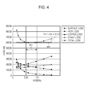
- Fig. 4 is a graph showing variations in losses with respect to the gap length ⁇ .
- verification data showing the relationships between the gap length ⁇ and the losses as illustrated in Fig. 4 is acquired.
- the losses include the surface loss, the iron loss, which is the main component of the fixed loss, the copper loss, which is the main component of the load loss, and stray loss, such as leakage magnetic flux.
- the total loss that is, the sum of the losses, is also acquired.
- the verification data may be measured values obtained by rotating the rotor 12 at a high rotation speed while changing the gap length ⁇ , or simulated values obtained by using, for example, a function including the gap length ⁇ as a parameter.
- the horizontal axis represents the ratio ⁇ /GD of the gap length ⁇ to the inner diameter GD of the stator core 11a.
- the surface loss is included in the verification data. More specifically, in the present embodiment, the gap length ⁇ is selected so that the sum of losses including the surface loss that occur when the high-voltage wires C are excited and the rotor 12 is rotated at a high rotation speed (that is, the total loss) is less than or equal to a threshold Th1 that corresponds to a target loss.
- the threshold Th1 which corresponds to the target loss, is to be determined before selecting the gap length ⁇ .
- An example of the method for determining the threshold Th1 will now be described with reference to Fig. 5 .
- Fig. 5 is a graph showing variations in losses excluding the surface loss with respect to the gap length ⁇ . This can be considered as an example of the related art in which the surface loss is not taken into consideration. In general, with regard to the losses of a rotating electrical machine, the efficiency is expected to be at a maximum when the iron loss and the copper loss are substantially equal to each other.
- the gap length ⁇ is selected so that the ratio ⁇ /GD satisfies ⁇ /GD ⁇ 0.5% (see arrow 501 in Fig. 5 ).
- the range of up to the value that is 1.5% greater than the minimum value min may be determined as the allowable range of the total loss (that is, the target loss) in the case where the surface loss is taken into consideration as illustrated in Fig. 4 .
- the gap length ⁇ may be selected so that the ratio ⁇ /GD satisfies 0.55% ⁇ ⁇ /GD ⁇ 1.0% (see arrow 401 in Fig. 4 ).
- Fig. 4 shows an example in which the threshold Th1 is set to the value that is 1.5% greater than the minimum value min, that is, 101.5% of the minimum value min.
- the threshold Th1 may instead be set to a value that is less than 101.5% of the minimum value min to further reduce the loss.
- the appropriate gap length ⁇ can be selected in consideration of the balance between the surface loss and the total loss.
- the ratio ⁇ /GD satisfies 0.55% ⁇ ⁇ /GD ⁇ 1.0% when the surface loss is taken into consideration, and ⁇ /GD ⁇ 0.5% when the surface loss is not taken into consideration.
- the ranges of the gap length ⁇ do not overlap.
- the selected gap length ⁇ clearly differs between the case in which the surface loss is taken into consideration and the case in which the surface loss is not taken into consideration.
- the manufacturing process clearly differs depending on whether or not the configuration illustrated in Fig. 1 is employed. Therefore, the efficiency of the manufacturing process can be improved.
- the threshold Th1 is determined on the basis of the total loss L1 at which the iron loss and the copper loss are substantially equal to each other in the case where the surface loss is not taken into consideration.
- the threshold may instead be determined on the basis of a total loss that is generally allowable or a value to which the gap length ⁇ can be set.
- Fig. 6 shows the case where another threshold Th2 is used.
- the verification data shown in Fig. 6 is the same as that in Fig. 4 .
- the threshold Th2 may be set to a value that is 103% of the minimum value min.
- the ratio ⁇ /GD in the case where the surface loss is taken into consideration as illustrated in Fig. 6 is 0.5% or more and 1.1% or less. Therefore, in this case, the gap length ⁇ may be selected so that the ratio ⁇ /GD satisfies 0.5% ⁇ ⁇ /GD ⁇ 1.1% (see arrow 601 in Fig. 6 ).
- the value to which the gap length ⁇ can be set is such that the ratio ⁇ /GD is 0.6% or less.
- the ratio ⁇ /GD satisfies 0.5% ⁇ ⁇ /GD ⁇ 1.1% when the surface loss is taken into consideration, and ⁇ /GD ⁇ 0.6% when the surface loss is not taken into consideration. Therefore, unlike the examples illustrated in Figs. 4 and 5 , the ranges of the gap length ⁇ partially overlap.
- the gap length ⁇ for when the surface loss is taken into consideration and that for when the surface loss is not taken into consideration may be set to the same value, and there is an advantage that, for example, a common manufacturing step may be employed in both cases.
- Fig. 6 shows an example in which the threshold Th2 is 103% of the minimum value min.
- the threshold Th2 may instead be set to a value that is less than 103% of the minimum value min to further reduce the loss.
- induction motors having a rated output of 500 kw (kilowatts) or more and 5000 kw or less are relatively easy to manufacture when the gap length ⁇ of the gap g is set so that the ratio ⁇ /GD satisfies 0.37% ⁇ ⁇ /GD ⁇ 0.9%.
- the manufacturing efficiency can be improved by selecting the gap length ⁇ so that the ratio ⁇ /GD satisfies 0.55% ⁇ ⁇ /GD ⁇ 0.9%.
- the manufacturing efficiency can be improved by selecting the gap length ⁇ so that the ratio ⁇ /GD satisfies 0.5% ⁇ ⁇ /GD ⁇ 0.9%.
- the rotating electrical machine includes a rotor and a stator. Permanent magnets are attached to the rotor.
- the stator opposes the rotor with a gap provided therebetween, and has open slots that open toward the rotor and in which high-voltage wires are installed.
- the gap has a gap length at which the sum of losses including a surface loss that occur when the high-voltage wires are excited and the rotor is rotated at a high rotation speed is less than or equal to a threshold that corresponds to a target loss.
- the rotating electrical machine according to the embodiment is capable of performing low-loss, high-efficiency high-speed rotation.
- the high-voltage wires are installed in the open slots.
- the surface loss may be initially reduced depending on the winding method of the high-voltage wires.
- the surface loss that is generated may be reduced by installing the high-voltage wires in the open slots in the fractional slot winding configuration, in which the number of slots per pole per phase is a fraction.
- the threshold corresponding to the target loss may be determined by taking into account the amount of reduction in the surface loss that can be achieved by the fractional slot winding configuration.
Landscapes
- Engineering & Computer Science (AREA)
- Power Engineering (AREA)
- Iron Core Of Rotating Electric Machines (AREA)
- Permanent Magnet Type Synchronous Machine (AREA)
Applications Claiming Priority (1)
| Application Number | Priority Date | Filing Date | Title |
|---|---|---|---|
| JP2013080699A JP2014204614A (ja) | 2013-04-08 | 2013-04-08 | 回転電機 |
Publications (1)
| Publication Number | Publication Date |
|---|---|
| EP2790307A2 true EP2790307A2 (de) | 2014-10-15 |
Family
ID=50439288
Family Applications (1)
| Application Number | Title | Priority Date | Filing Date |
|---|---|---|---|
| EP14163850.2A Withdrawn EP2790307A2 (de) | 2013-04-08 | 2014-04-08 | Elektrische Drehmaschine |
Country Status (4)
| Country | Link |
|---|---|
| US (1) | US20140300244A1 (de) |
| EP (1) | EP2790307A2 (de) |
| JP (1) | JP2014204614A (de) |
| CN (1) | CN104104199A (de) |
Citations (1)
| Publication number | Priority date | Publication date | Assignee | Title |
|---|---|---|---|---|
| JP2001028852A (ja) | 2000-01-01 | 2001-01-30 | Hitachi Ltd | 永久磁石回転型回転電機及びその製造方法 |
Family Cites Families (15)
| Publication number | Priority date | Publication date | Assignee | Title |
|---|---|---|---|---|
| US4045698A (en) * | 1973-11-28 | 1977-08-30 | Morrill Wayne J | Small air gap motor |
| JPH03289340A (ja) * | 1990-03-31 | 1991-12-19 | Toshiba Corp | 電動機 |
| JPH059154U (ja) * | 1991-07-05 | 1993-02-05 | 三菱電機株式会社 | 回転電機の磁性楔 |
| FI92114C (fi) * | 1992-07-07 | 1994-09-26 | High Speed Tech Ltd Oy | Epätahtisähkökone ja sen yhteydessä käytettävät roottori ja staattori |
| JPH11285183A (ja) * | 1998-03-26 | 1999-10-15 | Fanuc Ltd | 同期電動機のロータ構造 |
| JP2000354357A (ja) * | 1999-06-08 | 2000-12-19 | Meidensha Corp | 偏平回転電機及びこれの巻線作業に用いる巻線治具 |
| JP2001057746A (ja) * | 1999-08-18 | 2001-02-27 | Meidensha Corp | モータ構造 |
| JP2006217740A (ja) * | 2005-02-04 | 2006-08-17 | Kofu Meidensha:Kk | 超高速回転用ブラシレスモータ |
| JP4682100B2 (ja) * | 2006-07-13 | 2011-05-11 | 株式会社日立製作所 | 回転電機 |
| FI119748B (fi) * | 2006-12-21 | 2009-02-27 | Kone Corp | Sähkömoottori |
| JP4918891B2 (ja) * | 2007-07-11 | 2012-04-18 | 株式会社Ihi | 電動機付ターボチャージャ制御システム |
| CN201122885Y (zh) * | 2007-09-21 | 2008-09-24 | 广东省东莞电机有限公司 | 一种新型的三相异步电动机 |
| EP2093098B1 (de) * | 2008-02-21 | 2010-05-12 | Yamaha Hatsudoki Kabushiki Kaisha | Radantreibende Vorrichtung und elektrisches Fahrzeug damit |
| DE102009038928A1 (de) * | 2009-08-26 | 2010-11-04 | Schaeffler Technologies Gmbh & Co. Kg | Elektromotor |
| JP5299797B2 (ja) * | 2011-07-28 | 2013-09-25 | 西芝電機株式会社 | 高速回転用永久磁石形回転電機 |
-
2013
- 2013-04-08 JP JP2013080699A patent/JP2014204614A/ja not_active Ceased
-
2014
- 2014-04-03 CN CN201410133229.2A patent/CN104104199A/zh active Pending
- 2014-04-07 US US14/247,184 patent/US20140300244A1/en not_active Abandoned
- 2014-04-08 EP EP14163850.2A patent/EP2790307A2/de not_active Withdrawn
Patent Citations (1)
| Publication number | Priority date | Publication date | Assignee | Title |
|---|---|---|---|---|
| JP2001028852A (ja) | 2000-01-01 | 2001-01-30 | Hitachi Ltd | 永久磁石回転型回転電機及びその製造方法 |
Also Published As
| Publication number | Publication date |
|---|---|
| CN104104199A (zh) | 2014-10-15 |
| JP2014204614A (ja) | 2014-10-27 |
| US20140300244A1 (en) | 2014-10-09 |
Similar Documents
| Publication | Publication Date | Title |
|---|---|---|
| US10693331B2 (en) | Synchronous machine with magnetic rotating field reduction and flux concentration | |
| CN104393730B (zh) | 具有减小的扭矩波动的辐条永磁机及其制造方法 | |
| EP3016249B1 (de) | Elektrische axialdrehmaschine | |
| US10277099B2 (en) | Synchronous motor | |
| KR20170043464A (ko) | 회전 전기 기기, 회전자 철심의 제조 방법 | |
| CN103988400B (zh) | 用于旋转电机的转子,以及包括这种类型的转子的旋转电机 | |
| US20180159387A1 (en) | Rotating electric machine with a stator closed notches and, more particularly variable-reluctance synchronous electric machine assisted by permanent magnets | |
| EP2466733A2 (de) | Synchronmotor | |
| JP6668844B2 (ja) | 回転電機 | |
| US11201529B2 (en) | Rotary electric machine | |
| EP2658091A2 (de) | Rotoranordnung | |
| JP6048191B2 (ja) | マルチギャップ型回転電機 | |
| JP2011097660A (ja) | 回転電機およびその固定子 | |
| JP2017169419A (ja) | 回転電機の固定子 | |
| JP2018519782A (ja) | 永久磁石電動機 | |
| CN106953432B (zh) | 旋转电机 | |
| CN107534327B (zh) | 定子芯、永久磁铁同步电动机 | |
| CN104104171A (zh) | 电机转子 | |
| JP2017085745A (ja) | リラクタンス式同期回転電機 | |
| WO2018168146A1 (ja) | 回転電機及び回転電機システム | |
| JP2010045870A (ja) | 回転機 | |
| US20180294686A1 (en) | Stator for Rotating Electric Machine | |
| US20210226491A1 (en) | Rotor and motor | |
| US10897165B2 (en) | Permanent magnet synchronous motor | |
| EP2790307A2 (de) | Elektrische Drehmaschine |
Legal Events
| Date | Code | Title | Description |
|---|---|---|---|
| PUAI | Public reference made under article 153(3) epc to a published international application that has entered the european phase |
Free format text: ORIGINAL CODE: 0009012 |
|
| 17P | Request for examination filed |
Effective date: 20140408 |
|
| AK | Designated contracting states |
Kind code of ref document: A2 Designated state(s): AL AT BE BG CH CY CZ DE DK EE ES FI FR GB GR HR HU IE IS IT LI LT LU LV MC MK MT NL NO PL PT RO RS SE SI SK SM TR |
|
| AX | Request for extension of the european patent |
Extension state: BA ME |
|
| STAA | Information on the status of an ep patent application or granted ep patent |
Free format text: STATUS: THE APPLICATION IS DEEMED TO BE WITHDRAWN |
|
| 18D | Application deemed to be withdrawn |
Effective date: 20161101 |