EP2787220B1 - Befestigungselement für den Möbelbau - Google Patents
Befestigungselement für den Möbelbau Download PDFInfo
- Publication number
- EP2787220B1 EP2787220B1 EP14163344.6A EP14163344A EP2787220B1 EP 2787220 B1 EP2787220 B1 EP 2787220B1 EP 14163344 A EP14163344 A EP 14163344A EP 2787220 B1 EP2787220 B1 EP 2787220B1
- Authority
- EP
- European Patent Office
- Prior art keywords
- holding
- holding part
- adjustment part
- fitting element
- furniture
- Prior art date
- Legal status (The legal status is an assumption and is not a legal conclusion. Google has not performed a legal analysis and makes no representation as to the accuracy of the status listed.)
- Active
Links
Images

Classifications
-
- F—MECHANICAL ENGINEERING; LIGHTING; HEATING; WEAPONS; BLASTING
- F16—ENGINEERING ELEMENTS AND UNITS; GENERAL MEASURES FOR PRODUCING AND MAINTAINING EFFECTIVE FUNCTIONING OF MACHINES OR INSTALLATIONS; THERMAL INSULATION IN GENERAL
- F16B—DEVICES FOR FASTENING OR SECURING CONSTRUCTIONAL ELEMENTS OR MACHINE PARTS TOGETHER, e.g. NAILS, BOLTS, CIRCLIPS, CLAMPS, CLIPS OR WEDGES; JOINTS OR JOINTING
- F16B12/00—Jointing of furniture or the like, e.g. hidden from exterior
- F16B12/10—Jointing of furniture or the like, e.g. hidden from exterior using pegs, bolts, tenons, clamps, clips, or the like
- F16B12/12—Jointing of furniture or the like, e.g. hidden from exterior using pegs, bolts, tenons, clamps, clips, or the like for non-metal furniture parts, e.g. made of wood, of plastics
- F16B12/24—Jointing of furniture or the like, e.g. hidden from exterior using pegs, bolts, tenons, clamps, clips, or the like for non-metal furniture parts, e.g. made of wood, of plastics using separate pins, dowels, or the like
-
- A—HUMAN NECESSITIES
- A47—FURNITURE; DOMESTIC ARTICLES OR APPLIANCES; COFFEE MILLS; SPICE MILLS; SUCTION CLEANERS IN GENERAL
- A47B—TABLES; DESKS; OFFICE FURNITURE; CABINETS; DRAWERS; GENERAL DETAILS OF FURNITURE
- A47B2230/00—Furniture jointing; Furniture with such jointing
- A47B2230/0029—Dowels
- A47B2230/0051—Two-piece dowels
Definitions
- Object of the present invention is to provide an improved fastener for furniture, especially with regard to a functionally correct provision of the fastener for pre-assembly and the subsequent error-free adjustment to set up the attachment function.
- the invention relates to a fastener for furniture, in particular a furniture fastener, with a holding part, which can be introduced for a fastening function in a recessed receiving volume and then adjustable in a holding position of the fastener by a widening of a holding portion on the holding part, and with a control part tuned to the holding part such that with a linear relative movement between the holding part and the functionally correct position attached to the holding part, the holding position can be established, wherein the actuating part remains in the holding position on the holding part.
- the essence of the invention is that on the control part over an outer contour of the actuating part projecting stop means are provided, wherein the stop means determine a position of insertion of the actuating part on the holding part, in which the functionally correct on the holding part mounted actuating part is inserted on the holding part and the control part and the holding part to each other are held, wherein in the insertion position of the holding portion is not adjusted.
- the fastening element In the first of the two separate parts or from the holding and adjusting the existing fastener element is properly attached to the holding part in a first step z. B. plugged so that it is automatically held on the holding part. The attachment function causing a stop position is not reached. In the state prepared in this way, the fastening element can be mounted or preassembled at any desired location, for example.
- the adjusting and the holding part can be held by friction or otherwise together. In the established by the linear relative movement holding position of the fastener this is clamped in the receiving volume by the expanded holding portion.
- the adjustment of the holding portion by the linear retraction or indentations of the adjusting member is effected in particular by an expansion to the outside or a spreading of the holding portion on the holding part.
- the holding portion is forcibly pressed against outer adjacent walls of the recessed receiving volume, for example, a blind hole in a wood material.
- the linear relative movement to achieve the holding position with the adjusting member is advantageously carried out in the insertion direction in which the actuating part can be moved to the holding part in order in the right position to be held.
- the stop means are over an envelope surface of the actuating part to the outside and can thus be effective when attaching the control part on the holding part.
- an anti-rotation device is provided, with which a rotational movement between the actuating part and the holding part is prevented around a longitudinal axis of the fastener in functionally correct attached to the holding part actuator.
- the rotation is especially important if by means of a screw which can be inserted in the longitudinal direction of the fastener in the control part, which is infected positionally correct on the holding part, by the screwing in the relative movement of the actuating and holding part is realized.
- the screw is only rotatable, but fixed in the longitudinal direction. Also, the holding part must be secured against rotation in this approach against rotation relative to adjacent sections.
- the anti-rotation guide sections comprises, which contribute to the leadership of the linear relative movement between the holding part and the control part and which are effective for adjusting the holding portion by a widening of the holding portion.
- cooperating sections can be provided on the setting part and on the holding part be, which circumferentially considered to the longitudinal axis of the fastener form a stop and a counter-stop and thus prevent twisting, but the facing portions can slide past each other in the longitudinal direction mutually leading, which takes place in the linear relative movement between the actuating and holding part.
- An insertion portion is present on the setting part, which engages with the functionally correct attachment of the adjusting part on the holding part in a receptacle on the holding part, wherein the stop means comprise at least one stop element which comes into abutment against a mating portion, without an adjustment of the holding portion.
- the introduction section on the adjusting part and the receptacle on the holding part are matched to one another and to the stop element, that the adjusting part is inserted so far into the holding part, that in the stop position of the stop element on the counter section, the adjusting part and the holding part are held together without the holding section undergoes an adjustment.
- the introduction section z. B. on the outside of the adjusting part is in the direction of insertion in particular widening or slightly conically widening formed, as well as in appropriate form the corresponding counter portion or the recording on the holding part.
- the at least one stop element is provided in such a way that starting from a functionally correct attached to the holding part actuator via the stop means, a resistance to a further linear relative movement between the actuating part and the holding part in Ansteckides to set up the holding position is provided.
- a person may be infected by the Adjusting the holding part to determine that the desired AnsteckSullivan the adjusting part is reached on the holding part.
- the actuator is then included in its correct insertion depth in the recording. Until reaching this insertion depth, the actuating part or its insertion section slides without resistance in the holding part or its inclusion.
- the at least one stop element is formed protruding outward on the actuating part.
- the stop element may be pin-shaped or comparatively narrow and elongated.
- An advantageous modification of the subject invention provides that exactly two protruding stop elements are present on the control part.
- the two stop elements with respect to a longitudinal axis of the actuating part are advantageously opposite to each other above.
- an opposite section on the holding part can serve an end face.
- the end face may be formed, for example, enclosing the recessed receptacle on the holding part.
- the stop elements are particularly similar. In principle, more than two stop elements may be present.
- the counter portion and the at least one stop element are coordinated such that, starting from the insertion position in the linear relative movement of the actuating part and holding part for setting the holding position, the at least one stop element moves away from the above position.
- the further linear relative movement is possible.
- a further impressions of the actuating part in the holding part is removed with the moving away of the stop element of the resistance by the stop element in the stop position against a relative movement of the actuating part and holding part in Ansteckraum.
- the stop element is present on the fastening element in such a way that, when a pushing-in force acting on the stop element is exceeded, the stop element, for example, articulates or is bent over in an articulated manner.
- the at least one stop element is provided on the fastening element such that the at least one stop element can be deflected and / or at least partially sheared in cooperation with the counterpart section during the relative movement of the setting part and holding part to set up the holding position.
- the bending and shearing can also be superimposed possible or first a bending and then at least a partial shearing done. A complete shearing of the stop element is possible.
- a matched to the at least one stop element cavity on the fastening element is formed such that the at least one stop element is immersed in the cavity when the relative movement between the holding part and the holding part functionally correct mounted adjusting part for setting the holding position.
- the cavity is in particular present on the part on which the at least one stop element is formed.
- two stop elements are present on the setting part, wherein each stop element is associated with a cavity or a recessed formed area.
- the cavity is related to a direction of insertion of the actuating part trailing the stop element or adjacent to the point at which the stop element protrudes.
- the stop element can be bent or sheared off at this point and automatically pressed with the relative movement of the actuating and holding part in the cavity.
- guiding portions cooperating with one another on the holding part and the setting part are present in such a way that the linear relative movement between the holding part and the setting part for the adjustment of the holding section is guided by the guide sections can be specified.
- a force effect in the direction transverse thereto or provided to the outside over the guide portions for example in the direction of relative movement obliquely aligned surfaces on the control part and mating surfaces on the holding part, so that widened by a wedge effect with the movement of these inclined surfaces of the holding section to the outside or spread.
- the guide portions advantageously comprise a conical or round-conical outer side on the setting part or on its insertion portion and on the holding part on the conical outside in the relative movement in abutting inside on the receiving of the holding part, wherein the inclination or spatial orientation of the outside and the inside are matched.
- the receptacle can have, for example, two sections or segments which can expand elastically outwards.
- the holding portion is formed by these sections, wherein externally a ribbed structure may be formed, whereby the pressing and Einhak Koch the holding portion is improved against walls of the receiving volume.
- the guide portions may be present on the rotation, wherein the guide portions contribute to the rotation and the expansion of the holding portion.
- the guide sections spatially mutually angled aligned guide surfaces which serve to guide the relative movement between the actuating part and the holding part and / or for adjusting the holding portion by a widening of the holding portion.
- the insertion section is provided on the control part with guide portions.
- a holding, positioning and adjustment function is provided with the introduction section.
- the invention also relates to a front hook for a furniture front part, which is connectable to a furniture side part over the front part fixable on the front door hook, wherein for fixing the front hook on the furniture front part, a fastening element for fixing the front hook on the furniture front part according to one of the aforementioned embodiments.
- a fastening element for fixing the front hook on the furniture front part according to one of the aforementioned embodiments.
- projecting pin on the holding part in prepared openings on the front hook to achieve a rotationally fixed attachment of the fastener on the front hook.
- the invention extends to furniture with furniture components, wherein fastening means are provided for the assembly of the furniture components, wherein the fastening means comprise a fastening element according to one of the above-mentioned embodiments.
- a fastener according to the invention designed as a fixing dowel 1 comprises a holding part 2 and a matching adjusting part 3.
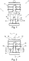
- FIG. 1 are the holding part 2 and the adjusting part 3 spaced from each other, wherein the holding part 2 and the adjusting part 3 are aligned with respect to each other positionally, so that moved by merging the holding part 2 and the adjusting part 3, for example by the adjusting member 3 in the direction of arrow P1 to the holding part 2 is, the two parts 2 and 3 are plugged together.
- FIG. 2 shows the mated state of the holding part 2 and setting part 3, wherein the adjusting part 3 is attached to the holding part 2 functionally correct.
- FIG. 3 shows the expansion dowel 1 in a holding position of the expansion anchor 1, in which the holding part 2 is held clamped in a corresponding, in particular cylindrically shaped opening or a prepared receiving volume (not shown), for example in a furniture part area.
- FIG. 2 The elastic expansion or spreading of a holding portion 11 with three circumferentially extending serrated ribs on the holding part 2 is in FIG. 2 indicated by arrows P4.
- the holding section 11 are set away from the outside or from the longitudinal axis L of the expansion anchor 1.
- FIG. 7 changed.
- the holding portion 11 can be pressed against the outside walls of a receiving volume and clamp the expansion dowel 1 in the relevant component.
- stop elements 12, 13 are over the length of the adjusting part 3 approximately centrally and projecting outwardly as a pin-shaped sections on the control part 3 available.
- the stop elements 12, 13 extend to the outside via an envelope H of the actuating part 3 via.
- the stop elements 12, 13 come in the insertion position according to FIG. 2 at an end portion 14 on the holding part 2 in Appendix.
- the outer wall 16 enclosing a passage opening 29 of the setting part 3 forms a positive or frictional connection with the holding part 2 on a frusto-conical plug-in section 15.
- the holding part 2 has a receptacle 17 with a through opening 28 on the holding part 2 bounding wall.
- On expansion dowel 1 also a rotation 18 is provided to rotate between the holding part 2 and the setting part 3 in the mutually infected state FIG. 2 or in the holding state according to FIG. 3 to prevent.
- the anti-rotation device 18 comprises two laterally outwardly on the adjusting part 3 protruding opposite rib-like guide cone 19, 20 which extend with its front end portion rounded into the insertion portion 15.
- the guide cone 19, 20 are tuned to engage in slots 21, 22 in the holding portion 11, wherein the slots 21, 22 are formed by a transversely extending through the holding part 2 recess.
- Each guide cone 19, 20 has obliquely to the longitudinal axis L against the insertion direction P1 flared edges 23 and 24, which come when inserting the adjusting part 3 in the holding part 2 at slot walls of each associated slot 21 and 22 into abutment and also essential to widening contribute the holding portion 11.
- the stop elements 12, 13 Upon reaching the stop position according to FIG. 3 the stop elements 12, 13 according to the movement arrows P2 and P3 (see FIG. 2 bent or at least partially sheared off, wherein the stop elements 12 and 13 in each case an associated cavity 25 and 26 immerse.
- the cavities 25, 26 are adjacent to the stop elements 12 and 13 on the adjusting part 3 matched to the stop elements 12 and 13 are formed.
- the bent or sheared stop elements 12 and 13 no obstacle to reach the holding position according to FIG. 3 more ready. Because the sheared or bent stop elements 12 and 13 can be found completely in the cavities 25 and 26, so that the holding position according to FIG. 3 is easily set up without jamming the stop members 12 and 13 between the actuating part 3 and the holding part 2.
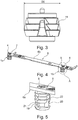
- FIGS. 4 to 7 is a front hook 6 with two expansion anchors 1 identical expansion dowels 1a and 1b shown.
- the respective screw 4 or 5 is thereby centrally inserted into the opening 28 in an end face 2a of the holding part 2 until an external thread of the screw 4 or 5 engages in the central passage opening 29 in the setting part 3 or cuts into it.
- By further screwing the screw 4 and 5 is then locked at the front hooks 6 via two insertion pins 9 and 10 inserted holding part 2, the control part 3 to the holding part 2 and thereby brought into the spread holding position.
- the two expansion dowels 1a and 1b are accordingly used for attaching the front hook 6 to a furniture part, wherein the furniture part prepared round holes for receiving the two rear on a back 6a on the front hook 6 projecting expansion dowel 1a, 1b are present, in which the expansion dowel 1a, 1b with the reaching of the holding position.
- front hooks 6 are for mounting the two expansion dowel 1a, 1b two round holes 7 and 8 prepared present and back additionally next to each two not visible in the figures wells, in which the two insertion pins 9, 10th fit exactly.
- the expansion dowel 1a, 1b in the assembled arrangement according to FIG. 2 at the back 6a of the front hook 6 infected, wherein the two opposite on the front side 2a Einsteckzapfen 9, 10 engage in the prepared existing recesses and hold the expansion dowel 1a, 1b against rotation on the front hook 6.
- the screws 4 and 5 are screwed into the two expansion dowels 1a, 1b or into the through-opening 29 on the setting part 3 from a front side 6b of the front hook 6, so that the arrangement according to FIG FIG. 5 is set up.
- the holding section 11 on the expansion anchor 1 is in this case in its initial position or in its non-expanded or not spread orientation according to FIG. 2 ,
Landscapes
- Engineering & Computer Science (AREA)
- General Engineering & Computer Science (AREA)
- Mechanical Engineering (AREA)
- Connection Of Plates (AREA)
- Furniture Connections (AREA)
Description
- Befestigungselemente für den Möbelbau mit einem aufweitbaren Halteabschnitt sind bekannt (vgl.
US 6,322,305 B1 ,DE 102 29 300 B3 oderFR 2 387 342 A1 - Aufgabe der vorliegenden Erfindung ist es, ein verbessertes Befestigungselement für den Möbelbau bereitzustellen insbesondere im Hinblick auf ein funktionsrichtiges Bereitstellen des Befestigungselements für eine Vormontage und die anschließende fehlerfreie Verstellung zum Einrichten der Befestigungsfunktion.
- Diese Aufgabe wird durch die unabhängigen Ansprüche gelöst.
- Die abhängigen Ansprüche betreffen vorteilhafte und zweckmäßige Weiterbildungen der Erfindung.
- Die Erfindung geht aus von einem Befestigungselement für den Möbelbau, insbesondere von einem Möbel-Befestigungselement, mit einem Halteteil, das für eine Befestigungsfunktion in ein vertieftes Aufnahmevolumen einbringbar und anschließend in eine Haltestellung des Befestigungselements durch ein Aufweiten eines Halteabschnitts am Halteteil verstellbar ist, und mit einem auf das Halteteil derart abgestimmten Stellteil, dass mit einer linearen Relativbewegung zwischen dem Halteteil und dem am Halteteil funktionsrichtig angebrachten Stellteil die Haltestellung einrichtbar ist, wobei das Stellteil in der Haltestellung am Halteteil verbleibt.
- Der Kern der Erfindung liegt darin, dass am Stellteil über eine Außenkontur des Stellteils vorstehende Anschlagmittel vorhanden sind, wobei die Anschlagmittel eine Einsteckposition des Stellteils am Halteteil bestimmen, in welcher das funktionsrichtig am Halteteil angebrachte Stellteil am Halteteil eingesteckt ist und das Stellteil und das Halteteil aneinander gehalten sind, wobei in der Einsteckposition der Halteabschnitt nicht verstellt ist.
- Bei dem zunächst aus den zwei getrennten Teilen bzw. aus dem Halte- und dem Stellteil bestehenden Befestigungselement wird in einem ersten Schritt das Stellteil funktionsrichtig am Halteteil angebracht z. B. angesteckt, so dass es selbsttätig am Halteteil gehalten ist. Die eine Befestigungsfunktion bewirkende Haltestellung ist dabei nicht erreicht. In dem so vorbereiteten Zustand kann das Befestigungselement an beliebigen Einsatzorten zum Beispiel angebracht bzw. vormontiert werden.
- Das Stell- und das Halteteil können dabei reibschlüssig oder anderweitig aneinander gehalten sein. In der durch die lineare Relativbewegung eingerichteten Haltestellung des Befestigungselements ist dieses in dem Aufnahmevolumen durch den aufgeweiteten Halteabschnitt festgeklemmt. Die Verstellung des Halteabschnitts durch das lineare Einziehen oder Eindrücken des Stellteils erfolgt insbesondere durch eine Aufweitung nach außen beziehungsweise eine Spreizung des Halteabschnitts am Halteteil. Der Halteabschnitt wird dabei zwangsweise an außen benachbarten Wandungen des vertieften Aufnahmevolumens zum Beispiel eines Sacklochs in einem Holzmaterial angepresst.
- Die lineare Relativbewegung zur Erreichung der Haltestellung mit dem Stellteil erfolgt vorteilhaft in der Einsteckrichtung, in welcher das Stellteil an das Halteteil heranführbar ist, um positionsrichtig daran gehalten zu werden.
- Die Anschlagmittel stehen über eine Hüllfläche des Stellteils nach außen über und können damit beim Anstecken des Stellteils am Halteteil sicher wirksam werden.
- Ein weiterer wesentlicher Aspekt der Erfindung liegt darin, dass eine Verdrehsicherung vorgesehen ist, mit welcher bei am Halteteil funktionsrichtig angebrachtem Stellteil eine Drehbewegung zwischen dem Stellteil und dem Halteteil um eine Längsachse des Befestigungselements unterbunden ist. Damit wird die lineare Relativbewegung von Stellteil und Halteteil zum Erreichen der Haltestellung nicht durch ein Verdrehen der beiden Teile beeinträchtigt. Die Verdrehsicherung ist insbesondere von Bedeutung, wenn mittels einer Schraube, welche in Längsrichtung des Befestigungselements in das Stellteil einbringbar ist, das am Halteteil positionsrichtig angesteckt ist, durch das Eindrehen der Schraube die Relativbewegung von Stell- und Halteteil realisiert ist. Dabei ist die Schraube nur verdrehbar, in Längsrichtung aber fixiert. Auch das Halteteil muss bei diesem Vorgehen gegen ein Verdrehen gegenüber angrenzenden Abschnitten drehgesichert sein.
- Mit der Verdrehsicherung bleibt der Steckzustand von Stell-und Halteteil zudem verbessert erhalten, da keine Relativbewegung von Stell- und Halteteil durch Verdrehen stattfinden kann, was ansonsten zu einem Lockern oder Lösen des angesteckten Stellteils vom Halteteil bewirken könnte.
- Weiter wird vorgeschlagen, dass gemäß einer vorteilhaften Variante der Erfindung die Verdrehsicherung Führungsabschnitte umfasst, welche zur Führung der linearen Relativbewegung zwischen dem Halteteil und dem Stellteil beitragen und welche zur Verstellung des Halteabschnitts durch ein Aufweiten des Halteabschnitts wirksam sind. Damit kann mit der Verdrehsicherung eine zusätzliche Funktion platzsparend bereitgestellt werden. Insbesondere können zusammenwirkende Abschnitte am Stellteil und am Halteteil bereitgestellt werden, welche umfänglich zur Längsachse des Befestigungselements betrachtet einen Anschlag und einen Gegenanschlag bilden und so das Verdrehen unterbinden, die sich zugewandten Abschnitte aber in Längsrichtung aneinander gegenseitig führend vorbeigleiten können, was bei der linearen Relativbewegung zwischen Stell- und Halteteil stattfindet.
- Mit der Verdrehsicherung kann zudem eingerichtet sein, dass das Stellteil am Halteteil ausschließlich in der funktionsrichtigen Ausrichtung der beiden Teile zueinander ansteckbar ist.
- Ein Einbringabschnitt ist am Stellteil vorhanden, der mit der funktionsrichtigen Anbringung des Stellteils am Halteteil in eine Aufnahme am Halteteil eingreift, wobei die Anschlagmittel wenigstens ein Anschlagelement umfassen, welches an einem Gegenabschnitt in Anlage kommt, ohne dass eine Verstellung des Halteabschnitts erfolgt. Der Einbringabschnitt am Stellteil und die Aufnahme am Halteteil sind so aufeinander und auf das Anschlagelement abgestimmt, dass das Stellteil so weit in das Halteteil einsteckbar ist, dass in der Anschlagstellung des Anschlagelements am Gegenabschnitt das Stellteil und das Halteteil aneinander gehalten sind, ohne dass der Halteabschnitt eine Verstellung erfährt.
- Der Einbringabschnitt z. B. außen am Stellteil ist in Einschiebrichtung insbesondere aufweitend beziehungsweise leicht konisch aufweitend ausgebildet, wie auch in entsprechender Form der dazugehörige Gegenabschnitt bzw. die Aufnahme am Halteteil.
- Insbesondere ist das wenigstens eine Anschlagelement derart bereitgestellt, dass ausgehend von einem am Halteteil funktionsrichtig angebrachten Stellteil über die Anschlagmittel ein Widerstand gegen eine weitere lineare Relativbewegung zwischen dem Stellteil und dem Halteteil in Ansteckrichtung zum Einrichten der Haltestellung bereitgestellt ist. Eine Person kann beim Anstecken des Stellteils am Halteteil feststellen, dass der gewünschte Ansteckzustand des Stellteils am Halteteil erreicht ist. Das Stellteil ist dann in seiner richtigen Einstecktiefe in der Aufnahme aufgenommen. Bis zum Erreichen dieser Einstecktiefe gleitet das Stellteil bzw. dessen Einbringabschnitt ohne Widerstand in dem Halteteil bzw. dessen Aufnahme.
- Das wenigstens eine Anschlagelement ist am Stellteil nach außen vorstehend ausgebildet. Beispielsweise kann das Anschlagelement stiftförmig bzw. vergleichsweise schmal und länglich ausgebildet sein.
- Eine vorteilhafte Modifikation des Erfindungsgegenstandes sieht vor, dass genau zwei vorstehende Anschlagelemente am Stellteil vorhanden sind. Insbesondere sind die beiden Anschlagelemente bezogen auf eine Längsachse des Stellteils vorteilhaft gegenüberliegend nach außen vorstehend. Als Gegenabschnitt am Halteteil kann eine endseitige Stirnfläche dienen. Die Stirnfläche kann beispielsweise umschließend um die vertiefte Aufnahme am Halteteil ausgebildet sein.
- Die Anschlagelemente sind insbesondere gleichartig ausgebildet. Grundsätzlich können auch mehr als zwei Anschlagelemente vorhanden sein.
- Es wird weiterhin vorgeschlagen, dass vorteilhafterweise der Gegenabschnitt und das wenigstens eine Anschlagelement derart aufeinander abgestimmt sind, dass ausgehend von der Einsteckposition bei der linearen Relativbewegung von Stellteil und Halteteil zum Einrichten der Haltestellung sich das wenigstens ein Anschlagelement aus der vorstehenden Stellung wegbewegt. Damit ist ausgehend vom Ansteckzustand von Stell- und Halteteil die weitergehende lineare Relativbewegung erst möglich. Mit zum Beispiel einem weitern Eindrücken des Stellteils in das Halteteil wird mit dem Wegbewegen des Anschlagelements der Widerstand durch das Anschlagelement in der Anschlagposition gegen eine Relativbewegung von Stellteil und Halteteil in Ansteckrichtung aufgehoben. Das Anschlagelement ist am Befestigungselement so vorhanden, dass es bei Überschreiten einer auf das Anschlagelement wirkenden Eindrückkraft das Anschlagelement beispielsweise gelenkig ausweicht bzw. umgebogen wird.
- Weiter ist es vorteilhaft, dass das wenigstens eine Anschlagelement derart am Befestigungselement vorhanden ist, dass das wenigstens eine Anschlagelement im Zusammenwirken mit dem Gegenabschnitt bei der Relativbewegung von Stellteil und Halteteil zum Einrichten der Haltestellung auslenkbar und/oder zumindest teilweise abscherbar ist. Das Verbiegen und Abscheren kann auch überlagert möglich sein beziehungsweise zunächst ein Verbiegen und dann zumindest ein teilweises Abscheren erfolgen. Auch ein vollständiges Abscheren des Anschlagelements ist möglich.
- Weiter ist es vorteilhaft, dass ein auf das wenigstens eine Anschlagelement abgestimmter Hohlraum am Befestigungselement derart ausgebildet ist, dass das wenigstens eine Anschlagelement in den Hohlraum eintaucht, wenn die Relativbewegung zwischen dem Halteteil und dem am Halteteil funktionsrichtig angebrachten Stellteil zum Einrichten der Haltestellung erfolgt. Der Hohlraum ist insbesondere an dem Teil vorhanden, an welchem das wenigstens eine Anschlagelement ausgebildet ist. Bevorzugt sind zwei Anschlagelemente am Stellteil vorhanden, wobei jedem Anschlagelement ein Hohlraum bzw. ein vertieft ausgebildeter Bereich zugeordnet ist. Der Hohlraum ist bezogen zu einer Einschieberichtung des Stellteils nachlaufend zum Anschlagelement bzw. benachbart zu der Stelle, an welcher das Anschlagelement absteht. So kann das Anschlagelement um diese Stelle umgebogen bzw. abgeschert und selbsttätig mit der Relativbewegung von Stell- und Halteteil in den Hohlraum eingedrückt werden.
- Weiter ist es vom Vorteil, dass an dem Halteteil und dem Stellteil miteinander zusammenwirkende Führungsabschnitte derart vorhanden sind, dass mit den Führungsabschnitten die lineare Relativbewegung zwischen dem Halteteil und dem Stellteil für die Verstellung des Halteabschnitts geführt vorgebbar ist. Insbesondere wird über die Führungsabschnitte, zum Beispiel in Richtung der Relativbewegung schräg ausgerichtete Flächen am Stellteil und Gegenflächen am Halteteil, eine Kraftwirkung in Richtung quer dazu bzw. nach außen bereitgestellt, so dass über eine Keilwirkung mit der Bewegung an diesen Schrägflächen der Halteabschnitt nach außen aufgeweitet bzw. gespreizt wird. Die Führungsabschnitte umfassen vorteilhaft eine kegelförmige bzw. rund-konische Außenseite am Stellteil bzw. an dessen Einbringabschnitt und am Halteteil eine an der konischen Außenseite bei der Relativbewegung in Anlage gelangende Innenseite an der Aufnahme des Halteteils, wobei die Neigung bzw. räumliche Ausrichtung der Außenseite und der Innenseite aufeinander abgestimmt sind. Die Aufnahme kann dabei zum Beispiel zwei Abschnitte bzw. Segmente aufweisen, welche elastisch nach außen aufweiten können. Vorteilhafterweise ist der Halteabschnitt durch diese Abschnitte gebildet, wobei außen eine gerippte Struktur ausgebildet sein kann, wodurch die Anpress- und Einhakwirkung des Halteabschnitts gegen Wandungen des Aufnahmevolumens verbessert ist.
- Außerdem können die Führungsabschnitte an der Verdrehsicherung vorhanden sein, wobei die Führungsabschnitte zur Verdrehsicherung und zur Aufweitung des Halteabschnitts beitragen.
- Auch sind vorteilhafterweise Begrenzungsmittel für eine Begrenzung der Relativbewegung von Stell- und Halteteil bzw. zur Begrenzung einer Einstecktiefe von Stellteil und Halteteil vorhanden. Damit wird auch ein maximal mögliches Aufweiten bzw. Spreizen des Halteabschnitts begrenzt vorgegeben.
- Es ist über dies vorteilhaft, dass die Führungsabschnitte räumlich zueinander abgewinkelt ausgerichtete Führungsflächen umfassen, welche zur Führung der Relativbewegung zwischen dem Stellteil und dem Halteteil und/oder zur Verstellung des Halteabschnitts durch ein Aufweiten des Halteabschnitts dienen.
- Es ist überdies von Vorteil, dass der Einbringabschnitt am Stellteil mit Führungsabschnitten versehen ist. Damit wird mit dem Einbringabschnitt eine Halte-, Positionier- und Verstellfunktion bereitgestellt.
- Die Erfindung betrifft außerdem einen Fronthaken für ein Möbelfrontteil, das mit einem Möbelseitenteil über dem am Möbelfrontteil festlegbaren Fronthaken verbindbar ist, wobei zur Festlegung des Fronthakens am Möbelfrontteil ein Befestigungselement zum Festlegen des Fronthakens am Möbelfrontteil gemäß einer der vorgenannten Ausbildungen vorhanden ist. Insbesondere greifen vorstehende Zapfen am Halteteil in vorbereitete Öffnungen am Fronthaken ein, um eine drehfeste Anbringung des Befestigungselements am Fronthaken zu erreichen.
- Außerdem erstreckt sich die Erfindung auf ein Möbel mit Möbelkomponenten, wobei Befestigungsmittel für den Zusammenbau der Möbelkomponenten vorgesehen sind, wobei die Befestigungsmittel ein Befestigungselement nach einem der oben erläuterten Ausbildungen umfassen.
- Weitere Merkmale und Vorteile der Erfindung sind anhand von in den Figuren dargestellten erfindungsgemäßen Ausführungsbeispielen näher erläutert. Im Einzelnen zeigt:
- Figur 1
- ein erfindungsgemäßes Befestigungselement von der Seite mit einem Stellteil und einem Halteteil,
- Figur 2
- das Befestigungselement gemäß
Figur 1 im aneinander angesteckten Zustand von Stellteil und Halteteil, - Figur 3
- das Befestigungselement gemäß
Figur 1 und 2 im Haltezustand, - Figur 4
- einen Fronthaken einer Schublade mit zwei daran aufgenommenen Befestigungselementen gemäß der
Figuren 1 bis 3 , - Figur 5
- eine vergrößerte Detaildarstellung gemäß des Bereichs A aus
Figur 4 , - Figur 6
- der Fronthaken gemäß
Figur 4 mit den daran angebrachten Befestigungselementen in der Haltestellung und - Figur 7
- ein vergrößertes Detail gemäß des Bereichs B aus
Figur 6 mit einem Befestigungselement in der Haltestellung. - Ein als Spreizdübel 1 aus einem Kunststoff ausgebildetes erfindungsgemäßes Befestigungselement weist ein Halteteil 2 und ein dazu passendes Stellteil 3 auf. Gemäß
Figur 1 sind das Halteteil 2 und das Stellteil 3 voneinander beabstandet, wobei das Halteteil 2 und das Stellteil 3 zueinander positionsrichtig ausgerichtet sind, so dass durch ein Zusammenführen des Halteteils 2 und des Stellteils 3, beispielsweise indem das Stellteil 3 gemäß Richtung Pfeil P1 zum Halteteil 2 hinbewegt wird, die beiden Teile 2 und 3 zusammensteckbar sind. -
Figur 2 zeigt den zusammengesteckten Zustand von Halteteil 2 und Stellteil 3, wobei das Stellteil 3 am Halteteil 2 funktionsrichtig angebracht ist. -
Figur 3 zeigt den Spreizdübel 1 in einer Haltestellung des Spreizdübels 1, in welcher das Halteteil 2 in einer entsprechenden insbesondere zylindrisch ausgeformten Öffnung beziehungsweise einem vorbereiteten Aufnahmevolumen (nicht gezeigt) beispielsweise in einem Möbelteilbereich geklemmt gehalten ist. - Zum Einrichten bzw. Erreichen der Haltestellung des Spreizdübels 1 gemäß
Figur 3 ist eine lineare Relativbewegung von Halteteil 2 und Stellteil 3 entlang der Längsachse L des Spreizdübels 1 notwendig. Dies kann zum Beispiel bei feststehendem Halteteil 2 durch ein Eindrücken des Stellteils 3 aus der inFigur 2 gezeigten Ansteckstellung in Richtung P1 sein. - Das elastische Aufweiten bzw. Aufspreizen eines Halteabschnitts 11 mit drei umfänglich verlaufenden gezackten Rippen am Halteteil 2 ist in
Figur 2 durch Pfeile P4 angedeutet. In der Haltestellung gemäßFigur 3 ist erkennbar, dass der Halteabschnitt 11 nach außen bzw. von der Längsachse L des Spreizdübels 1 wegversetzt sind. Dabei wird ein maßgeblicher Außendurchmesser des Halteabschnitts 11 von D1 im nicht aufgeweiteten Zustand gemäßFigur 2 bzw.Figur 5 auf D2 im aufgeweiteten Haltezustand gemäßFigur 3 bzw.Figur 7 verändert. Dabei können sich der Halteabschnitt 11 außen an Wandungen eines Aufnahmevolumens anpressend abstützen und den Spreizdübel 1 in dem betreffenden Bauteil verklemmen. - Im Einsteckzustand gemäß
Figur 2 gelangen zwei am Stellteil 3 vorhandene Anschlagelemente 12 und 13 in Anlage am Halteteil 2. Die Anschlagelemente 12, 13 sind über die Länge des Stellteils 3 in etwa mittig und nach außen abstehend als stiftförmig ausgebildete Abschnitte am Stellteil 3 vorhanden. Die Anschlagelemente 12, 13 reichen nach außen über eine Hüllfläche H des Stellteils 3 über. Dabei kommen die Anschlagelemente 12, 13 in der Einsteckposition gemäßFigur 2 an einem Stirnabschnitt 14 am Halteteil 2 in Anlage. - Im Einsteckzustand bildet die eine Durchgangsöffnung 29 des Stellteils 3 umschließende Außenwandung 16 an einem kegelstumpfförmigen Einsteckabschnitt 15 des Stellteils 3 eine form- bzw. reibschlüssige Verbindung mit dem Halteteil 2. Hierfür weist das Halteteil 2 eine Aufnahme 17 mit einer eine durchgehende Öffnung 28 am Halteteil 2 begrenzende Wandung auf. Beim weiteren Einschieben des Einsteckabschnitts 15 in die Aufnahme 17 vom in
Figur 2 dargestellten Einsteckzustand in den Haltezustand gemäßFigur 3 drückt die Außenwandung 16 den Halteabschnitt 11 zwangsweise nach außen. - Am Spreizdübel 1 ist außerdem eine Verdrehsicherung 18 vorgesehen, um ein Verdrehen zwischen dem Halteteil 2 und dem Stellteil 3 im aneinander angesteckten Zustand gemäß
Figur 2 beziehungsweise im Haltezustand gemäßFigur 3 zu verhindern. Die Verdrehsicherung 18 umfasst zwei seitlich außen am Stellteil 3 überstehenden gegenüberliegende rippenartige Führungskegel 19, 20 die sich mit ihrem vorne abgerundeten Endabschnitt bis in den Einsteckabschnitt 15 erstrecken. Die Führungskegel 19, 20 sind abgestimmt, in Schlitze 21, 22 im Halteabschnitt 11 einzugreifen, wobei die Schlitze 21, 22 durch eine quer durch das Halteteil 2 reichende Aussparung gebildet sind. - Jeder Führungskegel 19, 20 weist zur Längsachse L schräggestellte gegen die Einsteckrichtung P1 sich aufweitende Flanken 23 und 24 auf, welche beim Einschieben des Stellteils 3 in das Halteteil 2 an Schlitzwandungen des jeweils dazugehörigen Schlitzes 21 bzw. 22 in Anlage kommen und ebenfalls wesentlich zum Aufweiten des Halteabschnitts 11 beitragen.
- Damit wirken zwei voneinander getrennt ausgebildete Mechanismen zum Aufweiten des Halteabschnitts 11, einerseits durch das Zusammenspiel der Außenwandung 16 mit der Wandung der Öffnung 28 und andererseits durch das Zusammenwirken der Flanken 23, 24 mit Schlitzwandungen des jeweils dazugehörigen Schlitzes 21 bzw. 22.
- Beim Erreichen der Haltestellung gemäß
Figur 3 werden die Anschlagelemente 12, 13 gemäß der Bewegungspfeile P2 und P3 (sieheFigur 2 ) umgebogen bzw. zumindest teilweise abgeschert, wobei die Anschlagelemente 12 und 13 in jeweils einen zugeordneten Hohlraum 25 bzw. 26 eintauchen. Die Hohlräume 25, 26 sind benachbart zu den Anschlagelementen 12 und 13 am Stellteil 3 abgestimmt auf die Anschlagelemente 12 und 13 ausgebildet vorhanden. Damit stellen die umgebogenen beziehungsweise abgescherten Anschlagelemente 12 und 13 kein Hindernis zum Erreichen der Haltestellung gemäßFigur 3 mehr bereit. Denn die abgescherten beziehungsweise umgebogenen Anschlagelemente 12 und 13 können komplett in den Hohlräumen 25 und 26 Platz finden, sodass die Haltestellung gemäßFigur 3 problemlos ohne ein Verklemmen der Anschlagelemente 12 und 13 zwischen dem Stellteil 3 und dem Halteteil 2 eingerichtet wird. - In der Haltestellung gemäß
Figur 3 sind die Führungskegel 19, 20 vollständig in den Schlitzen 21, 22 aufgenommen, sodass ein ringförmiger Anschlagbereich 27 am Stellteil 3 an dem Stirnabschnitt 14 des Halteteils 2 anliegt. - In den
Figuren 4 bis 7 ist ein Fronthaken 6 mit zwei zum Spreizdübel 1 baugleichen Spreizdübeln 1a und 1b gezeigt. Dabei wird alternativ zum Eindrücken ein Heranziehen des Stellteils 3 zum Halteteil 2 mit einer Schraube 4 bzw. 5 realisiert. Die jeweilige Schraube 4 bzw. 5 wird dabei zentrisch in die Öffnung 28 in einer Stirnseite 2a des Halteteils 2 eingebracht bis ein Außengewinde der Schraube 4 bzw. 5 in die zentrische Durchgangsöffnung 29 im Stellteil 3 eingreift bzw. sich darin einschneidet. Durch weiteres Eindrehen der Schraube 4 bzw. 5 wird dann bei am Fronthaken 6 über zwei Einsteckzapfen 9 und 10 arretiert eingesteckten Halteteil 2 das Stellteil 3 an das Halteteil 2 herangezogen und dabei in die aufgespreizte Haltestellung gebracht. - Die beiden Spreizdübel 1a und 1b dienen demgemäß zur Anbringung des Fronthakens 6 an einem Möbelteil, wobei am Möbelteil vorbereitete Rundlöcher zur Aufnahme der beiden rückseitig an einer Rückseite 6a am Fronthaken 6 abstehenden Spreizdübel 1a, 1b vorhanden sind, in welchen sich die Spreizdübel 1a, 1b mit dem Erreichen der Haltestellung festhaken.
- Am aus einem flachen Metallstreifen gebildeten Fronthaken 6 sind zum Anbringen der beiden Spreizdübel 1a, 1b zwei Rundlöcher 7 und 8 vorbereitet vorhanden und rückseitig zusätzlich daneben je zwei in den Figuren nicht ersichtliche Vertiefungen, in welche die beiden Einsteckzapfen 9, 10 passgenau eingreifen.
- Zunächst werden die Spreizdübel 1a, 1b in der zusammengesteckten Anordnung gemäß
Figur 2 an der Rückseite 6a des Fronthakens 6 angesteckt, wobei die beiden an der Stirnseite 2a gegenüberliegenden Einsteckzapfen 9, 10 in die vorbereitet vorhandenen Vertiefungen eingreifen und die Spreizdübel 1a, 1b so verdrehsicher am Fronthaken 6 festhalten. Im nächsten Schritt werden von einer Vorderseite 6b des Fronthakens 6 die Schrauben 4 und 5 in die beiden Spreizdübel 1a, 1b bzw. in die Durchgangsöffnung 29 am Stellteil 3 eingeschraubt, so dass die Anordnung gemäßFigur 5 eingerichtet ist. Der Halteabschnitt 11 am Spreizdübel 1 befindet sich dabei in ihrer Ausgangsstellung beziehungsweise in seiner nicht aufgeweiteten beziehungsweise nicht gespreizten Ausrichtung gemäßFigur 2 . - Anschließend wir der Fronthaken 6 mit den daran vorbereitet vorhandenen Spreizdübeln 1a, 1b an dem Möbelteilabschnitt in den entsprechend vorbereiteten Öffnungen angesteckt, wobei in die Aufnahmevolumina der jeweilige an der Rückseite 6a des Fronthakens 6 überstehende Teil des Spreizdübels 1a und 1b hineinreicht.
- Anschließend werden die Schrauben 4 und 5 durch ein Verdrehwerkzeug wie z. B. ein Kreuzschlitzschraubendreher verdreht und das Stellteil 3 relativ zum Halteteil 2 gemäß Einsteckrichtung P1 herangezogen, sodass die gemäß
Figur 6 bzw. 7 erreichte Haltestellung der Spreizdübel 1a und 1b eingerichtet ist. -
- 1
- Spreizdübel
- 1a
- Spreizdübel
- 1b
- Spreizdübel
- 2
- Halteteil
- 2a
- Stirnseite
- 3
- Stellteil
- 4
- Schraube
- 5
- Schraube
- 6
- Fronthaken
- 6a
- Rückseite
- 6b
- Vorderseite
- 7
- Rundloch
- 8
- Rundloch
- 9
- Einsteckzapfen
- 10
- Einsteckzapfen
- 11
- Halteabschnitt
- 12
- Anschlagelement
- 13
- Anschlagelement
- 14
- Stirnabschnitt
- 15
- Einsteckabschnitt
- 16
- Außenwandung
- 17
- Aufnahme
- 18
- Verdrehsicherung
- 19
- Führungskegel
- 20
- Führungskegel
- 21
- Schlitz
- 22
- Schlitz
- 23
- Flanken
- 24
- Flanken
- 25
- Hohlraum
- 26
- Hohlraum
- 27
- Anschlagbereich
- 28
- Öffnung
- 29
- Durchgangsöffnung
Claims (12)
- Befestigungselement (1) für den Möbelbau, insbesondere Möbel-Befestigungselement, mit einem Halteteil (2), das für eine Befestigungsfunktion in ein vertieftes Aufnahmevolumen einbringbar und anschließend in eine Haltestellung des Befestigungselements (1) durch ein Aufweiten eines Halteabschnitts (11) am Halteteil (2) verstellbar ist, und mit einem auf das Halteteil (2) derart abgestimmten Stellteil (3), dass mit einer linearen Relativbewegung zwischen dem Halteteil (2) und dem am Halteteil (2) funktionsrichtig angebrachten Stellteil (3) die Haltestellung einrichtbar ist, wobei das Stellteil (3) in der Haltestellung am Halteteil (2) verbleibt, wobei
am Stellteil (3) über eine Außenkontur des Stellteils (3) vorstehende Anschlagmittel vorhanden sind, mit wenigstens einem Anschlagelement (12, 13), das am Stellteil (3) nach außen vorstehend ausgebildet ist, welches an einem Gegenabschnitt (14) in Anlage kommt, wobei die Anschlagmittel eine Einsteckposition des Stellteils (3) am Halteteil (2) bestimmen, in welcher das funktionsrichtig am Halteteil (2) angebrachte Stellteil (3) am Halteteil (2) eingesteckt ist und das Stellteil (3) und das Halteteil (2) aneinander gehalten sind, dadurch gekennzeichnet, dass in der Einsteckposition der Halteabschnitt (11) nicht verstellt ist und die Anschlagelemente (12, 13) ein Hindernis zum Erreichen der Haltestellung darstellen. - Befestigungselement nach Anspruch 1, dadurch gekennzeichnet dass eine Verdrehsicherung (18) vorgesehen ist, mit welcher bei am Halteteil (2) funktionsrichtig angebrachtem Stellteil (3) eine Drehbewegung zwischen dem Stellteil (3) und dem Halteteil (2) um eine Längsachse des Befestigungselement (1) unterbunden ist.
- Befestigungselement nach Anspruch 2, dadurch gekennzeichnet, dass die Verdrehsicherung (18) Führungsabschnitte (23, 24) umfasst, welche zur Führung der linearen Relativbewegung zwischen dem Halteteil (2) und dem Stellteil (3) beitragen und welche zur Verstellung des Halteabschnitts (11) durch ein Aufweiten des Halteabschnitts (11) wirksam sind.
- Befestigungselement nach einem der vorhergehenden Ansprüche, dadurch gekennzeichnet, dass genau zwei vorstehende Anschlagelemente (12, 13) am Stellteil (3) vorhanden sind.
- Befestigungselement nach einem der vorhergehenden Ansprüche 1 bis 3, dadurch gekennzeichnet, dass der Gegenabschnitt (14) und das wenigstens eine Anschlagelement (12, 13) derart aufeinander abgestimmt sind, dass ausgehend von der Einsteckposition bei der linearen Relativbewegung von Stellteil (3) und Halteteil (2) zum Einrichten der Haltestellung sich das wenigstens eine Anschlagelement (12, 13) aus der vorstehenden Stellung wegbewegt.
- Befestigungselement nach einem der vorhergehenden Ansprüche 1 bis 3 und 5, dadurch gekennzeichnet, dass das wenigstens eine Anschlagelement (12, 13) derart am Befestigungselement (1) vorhanden ist, dass das wenigstens eine Anschlagelement (12, 13) im Zusammenwirken mit dem Gegenabschnitt (14) bei der Relativbewegung von Stellteil (3) und Halteteil (2) zum Einrichten der Haltestellung auslenkbar und/oder zumindest teilweise abscherbar ist.
- Befestigungselement nach einem der vorhergehenden Ansprüche 1 bis 3, 5 und 6, dadurch gekennzeichnet, dass ein auf das wenigstens eine Anschlagelement (12, 13) abgestimmter Hohlraum (25, 26) am Befestigungselement (1) derart ausgebildet ist, dass das wenigstens eine Anschlagelement (12, 13) in den Hohlraum (25, 26) eintaucht, wenn die Relativbewegung zwischen dem Halteteil (2) und dem am Halteteil (2) funktionsrichtig angebrachten Stellteil (3) zum Einrichten der Haltestellung erfolgt.
- Befestigungselement nach einem der vorhergehenden Ansprüche, dadurch gekennzeichnet, dass an dem Halteteil (2) und dem Stellteil (3) miteinander zusammenwirkende Führungsabschnitte derart vorhanden sind, dass mit den Führungsabschnitten die lineare Relativbewegung zwischen dem Halteteil (2) und dem Stellteil (3) für die Verstellung des Halteabschnitts (11) geführt vorgebbar ist.
- Befestigungselement nach Anspruch 8, dadurch gekennzeichnet, dass die Führungsabschnitte räumlich zueinander abgewinkelt ausgerichtete Führungsflächen umfassen, welche zur Führung der Relativbewegung zwischen dem Stellteil (3) und dem Halteteil (2) und/oder zur Verstellung des Halteabschnitts (11) durch ein Aufweiten des Halteabschnitts (11) dienen.
- Befestigungselement nach einem der vorhergehenden Ansprüche, dadurch gekennzeichnet, dass der Einbringabschnitt (15) am Stellteil (3) mit Führungsabschnitten versehen ist.
- Fronthaken (6) für ein Möbelfrontteil, das mit einem Möbelseitenteil über den am Möbelfrontteil festlegbaren Fronthaken (6) verbindbar ist, dadurch gekennzeichnet, dass zur Festlegung des Fronthakens (6) am Möbelfrontteil ein Befestigungselement (1) zum Festlegen des Fronthakens (6) am Möbelfrontteil nach einem der vorhergehenden Ansprüche vorhanden ist.
- Möbel mit Möbelkomponenten, wobei Befestigungsmittel für den Zusammenbau der Möbelkomponenten vorgesehen sind, dadurch gekennzeichnet, dass die Befestigungsmittel ein Befestigungselement (1) nach einem der Ansprüche 1 bis 10 umfassen.
Applications Claiming Priority (1)
| Application Number | Priority Date | Filing Date | Title |
|---|---|---|---|
| DE202013003073.9U DE202013003073U1 (de) | 2013-04-04 | 2013-04-04 | Befestigungselement für den Möbelbau |
Publications (3)
| Publication Number | Publication Date |
|---|---|
| EP2787220A2 EP2787220A2 (de) | 2014-10-08 |
| EP2787220A3 EP2787220A3 (de) | 2015-02-18 |
| EP2787220B1 true EP2787220B1 (de) | 2017-02-01 |
Family
ID=50424115
Family Applications (1)
| Application Number | Title | Priority Date | Filing Date |
|---|---|---|---|
| EP14163344.6A Active EP2787220B1 (de) | 2013-04-04 | 2014-04-03 | Befestigungselement für den Möbelbau |
Country Status (2)
| Country | Link |
|---|---|
| EP (1) | EP2787220B1 (de) |
| DE (1) | DE202013003073U1 (de) |
Families Citing this family (3)
| Publication number | Priority date | Publication date | Assignee | Title |
|---|---|---|---|---|
| DE202015105329U1 (de) * | 2015-10-08 | 2017-01-11 | Grass Gmbh | Dübelanordnung für eine Vorrichtung zum Verbinden zweier Möbelelemente |
| AT519915B1 (de) * | 2017-05-11 | 2020-11-15 | Blum Gmbh Julius | Dübel zum Befestigen von Beschlagteilen |
| US11898584B2 (en) | 2020-02-07 | 2024-02-13 | Hni Technologies Inc. | Tool-less fastening system |
Family Cites Families (6)
| Publication number | Priority date | Publication date | Assignee | Title |
|---|---|---|---|---|
| DE2457172C2 (de) * | 1974-12-04 | 1984-09-27 | Paul Hettich & Co, 4983 Kirchlengern | Montageplatte für einen Scharnierarm |
| DE2701510A1 (de) * | 1977-01-15 | 1978-07-20 | Upat Max Langensiepen Kg | Duebel mit huelse und spreizkoerper |
| DE2815013A1 (de) * | 1977-04-15 | 1978-10-26 | Blum Gmbh Julius | Montageplatte |
| DE9307729U1 (de) * | 1993-05-21 | 1993-11-04 | Solidor Kunststoff und Metall Produktionsgesellschaft mbH (SKM), 37308 Heilbad Heiligenstadt | Spreizkörper |
| DE19915119B4 (de) * | 1999-04-01 | 2006-11-16 | Karl Simon Gmbh & Co. Kg | Montageelement für den Möbelbau |
| DE10229300B3 (de) * | 2002-06-29 | 2004-03-25 | Werthmüller Systeme Geisa GmbH & Co.KG | Verbindungssystem für Bauteile, insbesondere für Möbelteile |
-
2013
- 2013-04-04 DE DE202013003073.9U patent/DE202013003073U1/de not_active Expired - Lifetime
-
2014
- 2014-04-03 EP EP14163344.6A patent/EP2787220B1/de active Active
Also Published As
| Publication number | Publication date |
|---|---|
| DE202013003073U1 (de) | 2014-07-08 |
| EP2787220A2 (de) | 2014-10-08 |
| EP2787220A3 (de) | 2015-02-18 |
Similar Documents
| Publication | Publication Date | Title |
|---|---|---|
| EP2742199B1 (de) | Befestigungsanordnung zur befestigung eines bauteils an einer nut eines fensters, einer tür oder dergleichen | |
| DE202015008847U1 (de) | Befestigungsvorrichtung | |
| EP3122981B1 (de) | Dichtungsvorrichtung und befestigungsmittel | |
| DE102012219154A1 (de) | Lösbare Verbindungsvorrichtung für die werkzeuglose Montage | |
| DE102013111400A1 (de) | Befestigungsvorrichtung für zwei Befestigungszustände | |
| WO2007014697A1 (de) | Befetigungselement zum einsetzen in eine bohrung | |
| WO2016146272A1 (de) | Halteelement für einen tür- oder fensterdrücker und anordnung eines tür- oder fensterdrückers an einer aufnahmeöffnung eines fensterrahmens, eines türblatts oder dergleichen | |
| EP3476252A1 (de) | Haltevorrichtung für einen regalboden an einer regalwand und regal mit einer solchen haltevorrichtung | |
| EP2787220B1 (de) | Befestigungselement für den Möbelbau | |
| EP3401556A1 (de) | Frontblenden-verbindungsbeschlag | |
| DE19642914C2 (de) | Dübel | |
| DE60200329T2 (de) | Regalbodenstütze für eine schnelle Montage, für Möbel und dergleichen | |
| AT519920B1 (de) | Befestigungsvorrichtung | |
| DE102015113737B3 (de) | Sensor | |
| EP3592993A1 (de) | Spannverbinder und befestigungsanordnung mit einem solchen | |
| EP1473468B1 (de) | Steckverbindung | |
| DE202007001276U1 (de) | Vorrichtung zur Befestigung eines Beschlagteils | |
| EP1735539B1 (de) | Befestigungssystem | |
| EP3291395B1 (de) | Installationsgerät für die deckenmontage | |
| EP3093937A1 (de) | Sockelteil für elektrische installationsgeräte | |
| EP0058709A1 (de) | Ankerbolzen | |
| DE102014103637B4 (de) | Topflocheinsatz, Blendenbefestigungselement und Topfscharnier | |
| EP2116800B1 (de) | Kältegerät und zugehöriges Montageelement für dessen Deckplatte | |
| WO2006097178A1 (de) | Beschlag zur befestigung in einer hinterschnittenen nut eines metall- oder kunststoffprofils | |
| DE10208624A1 (de) | Einstellbare Befestigungsvorrichtung |
Legal Events
| Date | Code | Title | Description |
|---|---|---|---|
| PUAI | Public reference made under article 153(3) epc to a published international application that has entered the european phase |
Free format text: ORIGINAL CODE: 0009012 |
|
| 17P | Request for examination filed |
Effective date: 20140403 |
|
| AK | Designated contracting states |
Kind code of ref document: A2 Designated state(s): AL AT BE BG CH CY CZ DE DK EE ES FI FR GB GR HR HU IE IS IT LI LT LU LV MC MK MT NL NO PL PT RO RS SE SI SK SM TR |
|
| AX | Request for extension of the european patent |
Extension state: BA ME |
|
| PUAL | Search report despatched |
Free format text: ORIGINAL CODE: 0009013 |
|
| AK | Designated contracting states |
Kind code of ref document: A3 Designated state(s): AL AT BE BG CH CY CZ DE DK EE ES FI FR GB GR HR HU IE IS IT LI LT LU LV MC MK MT NL NO PL PT RO RS SE SI SK SM TR |
|
| AX | Request for extension of the european patent |
Extension state: BA ME |
|
| RIC1 | Information provided on ipc code assigned before grant |
Ipc: F16B 12/24 20060101AFI20150109BHEP |
|
| R17P | Request for examination filed (corrected) |
Effective date: 20150720 |
|
| RBV | Designated contracting states (corrected) |
Designated state(s): AL AT BE BG CH CY CZ DE DK EE ES FI FR GB GR HR HU IE IS IT LI LT LU LV MC MK MT NL NO PL PT RO RS SE SI SK SM TR |
|
| 17Q | First examination report despatched |
Effective date: 20151202 |
|
| GRAP | Despatch of communication of intention to grant a patent |
Free format text: ORIGINAL CODE: EPIDOSNIGR1 |
|
| INTG | Intention to grant announced |
Effective date: 20160822 |
|
| GRAS | Grant fee paid |
Free format text: ORIGINAL CODE: EPIDOSNIGR3 |
|
| STAA | Information on the status of an ep patent application or granted ep patent |
Free format text: STATUS: GRANT OF PATENT IS INTENDED |
|
| GRAA | (expected) grant |
Free format text: ORIGINAL CODE: 0009210 |
|
| STAA | Information on the status of an ep patent application or granted ep patent |
Free format text: STATUS: THE PATENT HAS BEEN GRANTED |
|
| AK | Designated contracting states |
Kind code of ref document: B1 Designated state(s): AL AT BE BG CH CY CZ DE DK EE ES FI FR GB GR HR HU IE IS IT LI LT LU LV MC MK MT NL NO PL PT RO RS SE SI SK SM TR |
|
| REG | Reference to a national code |
Ref country code: GB Ref legal event code: FG4D Free format text: NOT ENGLISH |
|
| REG | Reference to a national code |
Ref country code: CH Ref legal event code: EP Ref country code: AT Ref legal event code: REF Ref document number: 865848 Country of ref document: AT Kind code of ref document: T Effective date: 20170215 |
|
| REG | Reference to a national code |
Ref country code: IE Ref legal event code: FG4D Free format text: LANGUAGE OF EP DOCUMENT: GERMAN |
|
| REG | Reference to a national code |
Ref country code: DE Ref legal event code: R096 Ref document number: 502014002581 Country of ref document: DE |
|
| REG | Reference to a national code |
Ref country code: NL Ref legal event code: MP Effective date: 20170201 |
|
| REG | Reference to a national code |
Ref country code: LT Ref legal event code: MG4D |
|
| PG25 | Lapsed in a contracting state [announced via postgrant information from national office to epo] |
Ref country code: NO Free format text: LAPSE BECAUSE OF FAILURE TO SUBMIT A TRANSLATION OF THE DESCRIPTION OR TO PAY THE FEE WITHIN THE PRESCRIBED TIME-LIMIT Effective date: 20170501 Ref country code: IS Free format text: LAPSE BECAUSE OF FAILURE TO SUBMIT A TRANSLATION OF THE DESCRIPTION OR TO PAY THE FEE WITHIN THE PRESCRIBED TIME-LIMIT Effective date: 20170601 Ref country code: FI Free format text: LAPSE BECAUSE OF FAILURE TO SUBMIT A TRANSLATION OF THE DESCRIPTION OR TO PAY THE FEE WITHIN THE PRESCRIBED TIME-LIMIT Effective date: 20170201 Ref country code: LT Free format text: LAPSE BECAUSE OF FAILURE TO SUBMIT A TRANSLATION OF THE DESCRIPTION OR TO PAY THE FEE WITHIN THE PRESCRIBED TIME-LIMIT Effective date: 20170201 Ref country code: GR Free format text: LAPSE BECAUSE OF FAILURE TO SUBMIT A TRANSLATION OF THE DESCRIPTION OR TO PAY THE FEE WITHIN THE PRESCRIBED TIME-LIMIT Effective date: 20170502 Ref country code: HR Free format text: LAPSE BECAUSE OF FAILURE TO SUBMIT A TRANSLATION OF THE DESCRIPTION OR TO PAY THE FEE WITHIN THE PRESCRIBED TIME-LIMIT Effective date: 20170201 |
|
| PG25 | Lapsed in a contracting state [announced via postgrant information from national office to epo] |
Ref country code: NL Free format text: LAPSE BECAUSE OF NON-PAYMENT OF DUE FEES Effective date: 20170201 Ref country code: PT Free format text: LAPSE BECAUSE OF FAILURE TO SUBMIT A TRANSLATION OF THE DESCRIPTION OR TO PAY THE FEE WITHIN THE PRESCRIBED TIME-LIMIT Effective date: 20170601 Ref country code: LV Free format text: LAPSE BECAUSE OF FAILURE TO SUBMIT A TRANSLATION OF THE DESCRIPTION OR TO PAY THE FEE WITHIN THE PRESCRIBED TIME-LIMIT Effective date: 20170201 Ref country code: SE Free format text: LAPSE BECAUSE OF FAILURE TO SUBMIT A TRANSLATION OF THE DESCRIPTION OR TO PAY THE FEE WITHIN THE PRESCRIBED TIME-LIMIT Effective date: 20170201 Ref country code: BG Free format text: LAPSE BECAUSE OF FAILURE TO SUBMIT A TRANSLATION OF THE DESCRIPTION OR TO PAY THE FEE WITHIN THE PRESCRIBED TIME-LIMIT Effective date: 20170501 Ref country code: RS Free format text: LAPSE BECAUSE OF FAILURE TO SUBMIT A TRANSLATION OF THE DESCRIPTION OR TO PAY THE FEE WITHIN THE PRESCRIBED TIME-LIMIT Effective date: 20170201 Ref country code: ES Free format text: LAPSE BECAUSE OF FAILURE TO SUBMIT A TRANSLATION OF THE DESCRIPTION OR TO PAY THE FEE WITHIN THE PRESCRIBED TIME-LIMIT Effective date: 20170201 Ref country code: PL Free format text: LAPSE BECAUSE OF FAILURE TO SUBMIT A TRANSLATION OF THE DESCRIPTION OR TO PAY THE FEE WITHIN THE PRESCRIBED TIME-LIMIT Effective date: 20170201 |
|
| PGFP | Annual fee paid to national office [announced via postgrant information from national office to epo] |
Ref country code: TR Payment date: 20170420 Year of fee payment: 4 |
|
| PG25 | Lapsed in a contracting state [announced via postgrant information from national office to epo] |
Ref country code: CZ Free format text: LAPSE BECAUSE OF FAILURE TO SUBMIT A TRANSLATION OF THE DESCRIPTION OR TO PAY THE FEE WITHIN THE PRESCRIBED TIME-LIMIT Effective date: 20170201 Ref country code: IT Free format text: LAPSE BECAUSE OF FAILURE TO SUBMIT A TRANSLATION OF THE DESCRIPTION OR TO PAY THE FEE WITHIN THE PRESCRIBED TIME-LIMIT Effective date: 20170201 Ref country code: EE Free format text: LAPSE BECAUSE OF FAILURE TO SUBMIT A TRANSLATION OF THE DESCRIPTION OR TO PAY THE FEE WITHIN THE PRESCRIBED TIME-LIMIT Effective date: 20170201 Ref country code: RO Free format text: LAPSE BECAUSE OF FAILURE TO SUBMIT A TRANSLATION OF THE DESCRIPTION OR TO PAY THE FEE WITHIN THE PRESCRIBED TIME-LIMIT Effective date: 20170201 Ref country code: SK Free format text: LAPSE BECAUSE OF FAILURE TO SUBMIT A TRANSLATION OF THE DESCRIPTION OR TO PAY THE FEE WITHIN THE PRESCRIBED TIME-LIMIT Effective date: 20170201 |
|
| REG | Reference to a national code |
Ref country code: DE Ref legal event code: R097 Ref document number: 502014002581 Country of ref document: DE |
|
| PG25 | Lapsed in a contracting state [announced via postgrant information from national office to epo] |
Ref country code: SM Free format text: LAPSE BECAUSE OF FAILURE TO SUBMIT A TRANSLATION OF THE DESCRIPTION OR TO PAY THE FEE WITHIN THE PRESCRIBED TIME-LIMIT Effective date: 20170201 Ref country code: DK Free format text: LAPSE BECAUSE OF FAILURE TO SUBMIT A TRANSLATION OF THE DESCRIPTION OR TO PAY THE FEE WITHIN THE PRESCRIBED TIME-LIMIT Effective date: 20170201 |
|
| REG | Reference to a national code |
Ref country code: CH Ref legal event code: PL |
|
| PLBE | No opposition filed within time limit |
Free format text: ORIGINAL CODE: 0009261 |
|
| STAA | Information on the status of an ep patent application or granted ep patent |
Free format text: STATUS: NO OPPOSITION FILED WITHIN TIME LIMIT |
|
| 26N | No opposition filed |
Effective date: 20171103 |
|
| REG | Reference to a national code |
Ref country code: IE Ref legal event code: MM4A |
|
| REG | Reference to a national code |
Ref country code: FR Ref legal event code: ST Effective date: 20171229 |
|
| PG25 | Lapsed in a contracting state [announced via postgrant information from national office to epo] |
Ref country code: FR Free format text: LAPSE BECAUSE OF NON-PAYMENT OF DUE FEES Effective date: 20170502 Ref country code: MC Free format text: LAPSE BECAUSE OF FAILURE TO SUBMIT A TRANSLATION OF THE DESCRIPTION OR TO PAY THE FEE WITHIN THE PRESCRIBED TIME-LIMIT Effective date: 20170201 |
|
| PG25 | Lapsed in a contracting state [announced via postgrant information from national office to epo] |
Ref country code: CH Free format text: LAPSE BECAUSE OF NON-PAYMENT OF DUE FEES Effective date: 20170430 Ref country code: SI Free format text: LAPSE BECAUSE OF FAILURE TO SUBMIT A TRANSLATION OF THE DESCRIPTION OR TO PAY THE FEE WITHIN THE PRESCRIBED TIME-LIMIT Effective date: 20170201 Ref country code: LI Free format text: LAPSE BECAUSE OF NON-PAYMENT OF DUE FEES Effective date: 20170430 Ref country code: LU Free format text: LAPSE BECAUSE OF NON-PAYMENT OF DUE FEES Effective date: 20170403 |
|
| REG | Reference to a national code |
Ref country code: BE Ref legal event code: MM Effective date: 20170430 |
|
| PG25 | Lapsed in a contracting state [announced via postgrant information from national office to epo] |
Ref country code: IE Free format text: LAPSE BECAUSE OF NON-PAYMENT OF DUE FEES Effective date: 20170403 |
|
| PG25 | Lapsed in a contracting state [announced via postgrant information from national office to epo] |
Ref country code: BE Free format text: LAPSE BECAUSE OF NON-PAYMENT OF DUE FEES Effective date: 20170430 |
|
| PG25 | Lapsed in a contracting state [announced via postgrant information from national office to epo] |
Ref country code: MT Free format text: LAPSE BECAUSE OF FAILURE TO SUBMIT A TRANSLATION OF THE DESCRIPTION OR TO PAY THE FEE WITHIN THE PRESCRIBED TIME-LIMIT Effective date: 20170201 |
|
| GBPC | Gb: european patent ceased through non-payment of renewal fee |
Effective date: 20180403 |
|
| PG25 | Lapsed in a contracting state [announced via postgrant information from national office to epo] |
Ref country code: GB Free format text: LAPSE BECAUSE OF NON-PAYMENT OF DUE FEES Effective date: 20180403 |
|
| PG25 | Lapsed in a contracting state [announced via postgrant information from national office to epo] |
Ref country code: HU Free format text: LAPSE BECAUSE OF FAILURE TO SUBMIT A TRANSLATION OF THE DESCRIPTION OR TO PAY THE FEE WITHIN THE PRESCRIBED TIME-LIMIT; INVALID AB INITIO Effective date: 20140403 |
|
| PG25 | Lapsed in a contracting state [announced via postgrant information from national office to epo] |
Ref country code: CY Free format text: LAPSE BECAUSE OF FAILURE TO SUBMIT A TRANSLATION OF THE DESCRIPTION OR TO PAY THE FEE WITHIN THE PRESCRIBED TIME-LIMIT Effective date: 20170201 |
|
| PG25 | Lapsed in a contracting state [announced via postgrant information from national office to epo] |
Ref country code: MK Free format text: LAPSE BECAUSE OF FAILURE TO SUBMIT A TRANSLATION OF THE DESCRIPTION OR TO PAY THE FEE WITHIN THE PRESCRIBED TIME-LIMIT Effective date: 20170201 |
|
| PG25 | Lapsed in a contracting state [announced via postgrant information from national office to epo] |
Ref country code: AL Free format text: LAPSE BECAUSE OF FAILURE TO SUBMIT A TRANSLATION OF THE DESCRIPTION OR TO PAY THE FEE WITHIN THE PRESCRIBED TIME-LIMIT Effective date: 20170201 |
|
| PG25 | Lapsed in a contracting state [announced via postgrant information from national office to epo] |
Ref country code: TR Free format text: LAPSE BECAUSE OF NON-PAYMENT OF DUE FEES Effective date: 20180403 |
|
| REG | Reference to a national code |
Ref country code: DE Ref legal event code: R082 Ref document number: 502014002581 Country of ref document: DE Representative=s name: RAVENSPAT PATENTANWAELTE PARTNERSCHAFT MBB, DE |
|
| PGFP | Annual fee paid to national office [announced via postgrant information from national office to epo] |
Ref country code: DE Payment date: 20250418 Year of fee payment: 12 |
|
| PGFP | Annual fee paid to national office [announced via postgrant information from national office to epo] |
Ref country code: AT Payment date: 20250423 Year of fee payment: 12 |