EP2786674B1 - Küchenmöbel mit verfahrbarer Arbeitsplatte - Google Patents
Küchenmöbel mit verfahrbarer Arbeitsplatte Download PDFInfo
- Publication number
- EP2786674B1 EP2786674B1 EP14157381.6A EP14157381A EP2786674B1 EP 2786674 B1 EP2786674 B1 EP 2786674B1 EP 14157381 A EP14157381 A EP 14157381A EP 2786674 B1 EP2786674 B1 EP 2786674B1
- Authority
- EP
- European Patent Office
- Prior art keywords
- furniture
- worktop
- functional surface
- kitchen
- holding
- Prior art date
- Legal status (The legal status is an assumption and is not a legal conclusion. Google has not performed a legal analysis and makes no representation as to the accuracy of the status listed.)
- Active
Links
- 238000010438 heat treatment Methods 0.000 description 2
- 238000002360 preparation method Methods 0.000 description 2
- XAGFODPZIPBFFR-UHFFFAOYSA-N aluminium Chemical compound [Al] XAGFODPZIPBFFR-UHFFFAOYSA-N 0.000 description 1
- 229910052782 aluminium Inorganic materials 0.000 description 1
- 230000001419 dependent effect Effects 0.000 description 1
- 230000001627 detrimental effect Effects 0.000 description 1
- 238000006073 displacement reaction Methods 0.000 description 1
- 238000005485 electric heating Methods 0.000 description 1
- 230000006698 induction Effects 0.000 description 1
- 229920001296 polysiloxane Polymers 0.000 description 1
- 238000005096 rolling process Methods 0.000 description 1
Images



Classifications
-
- A—HUMAN NECESSITIES
- A47—FURNITURE; DOMESTIC ARTICLES OR APPLIANCES; COFFEE MILLS; SPICE MILLS; SUCTION CLEANERS IN GENERAL
- A47B—TABLES; DESKS; OFFICE FURNITURE; CABINETS; DRAWERS; GENERAL DETAILS OF FURNITURE
- A47B77/00—Kitchen cabinets
- A47B77/04—Provision for particular uses of compartments or other parts ; Compartments moving up and down, revolving parts
- A47B77/08—Provision for particular uses of compartments or other parts ; Compartments moving up and down, revolving parts for incorporating apparatus operated by power, including water power; for incorporating apparatus for cooking, cooling, or laundry purposes
-
- A—HUMAN NECESSITIES
- A47—FURNITURE; DOMESTIC ARTICLES OR APPLIANCES; COFFEE MILLS; SPICE MILLS; SUCTION CLEANERS IN GENERAL
- A47B—TABLES; DESKS; OFFICE FURNITURE; CABINETS; DRAWERS; GENERAL DETAILS OF FURNITURE
- A47B77/00—Kitchen cabinets
- A47B77/04—Provision for particular uses of compartments or other parts ; Compartments moving up and down, revolving parts
- A47B77/10—Provision for particular uses of compartments or other parts ; Compartments moving up and down, revolving parts with members movable outwards to a position of use, e.g. tables, ironing boards
- A47B77/12—Provision for particular uses of compartments or other parts ; Compartments moving up and down, revolving parts with members movable outwards to a position of use, e.g. tables, ironing boards for attachment of portable kitchen machines
-
- F—MECHANICAL ENGINEERING; LIGHTING; HEATING; WEAPONS; BLASTING
- F24—HEATING; RANGES; VENTILATING
- F24C—DOMESTIC STOVES OR RANGES ; DETAILS OF DOMESTIC STOVES OR RANGES, OF GENERAL APPLICATION
- F24C15/00—Details
- F24C15/30—Arrangements for mounting stoves or ranges in particular locations
Definitions
- the present invention relates to a kitchen furniture with a working and / or functional surface, in which at least one stove top is integrated.
- a cabinet as it is for example in the DE 10 2010 005 024.5 is described, in which a cabinet is shown, in which the upper storage compartments by a mechanism from the cabinet extendable and lowerable in front of the front of the cabinet so that wheelchair users can reach the storage compartments.
- the document DE 101 59 649 A1 further discloses an assembly having a cooktop supported on a kitchen worktop and adjustable between a storage position and a use position, wherein the cooktop is located in the storage position below the kitchen worktop and unusable and located above the kitchen worktop in the use position.
- the invention is based on the recognition that for the independent life of physically disabled people, the independent preparation of food is very significant.
- kitchen furniture are designed so that they are difficult to use by physically disabled people, such as short or wheelchair users.
- hobs to call which are usually integrated in a working or functional surface of a kitchen cabinet.
- stoves are understood to be all appliances which are suitable for the preparation of food in a working or functional area, such as electric heating fields, induction heating fields, gas heating fields, roasting surfaces, grilling surfaces and the like.
- Short - lived people or wheelchair users have the difficulty here to reach remote areas of the working and / or functional area, since it is usually accessible only from one side.
- This problem is inventively achieved in that the working or functional surface, in which at least one hotplate is integrated and is formed horizontally and vertically movable.
- the working and / or functional surface can be arranged so that it is easily accessible to anyone in all areas.
- the kitchen furniture according to the invention thus makes it possible to extend the working and / or functional area horizontally, for example from a kitchenette, and optionally to lower it to a height suitable for the user.
- a holding and driving device is provided with which the working and / or functional surface is held and moved.
- the movement of the working and / or functional surface can take place in such a way that the working and / or functional surface is aligned substantially horizontally in every position of the holding and driving device.
- the horizontal movement preferably corresponds to a movement in a horizontal plane perpendicular to an access side of the working and / or functional surface or of the furniture.
- the vertical movement is advantageously a movement transversely, in particular perpendicular to the horizontal plane, in particular along the access side of the working and / or functional surface or the furniture.
- the kitchen furniture has a front side, which usually corresponds to the access side.
- the front side is formed by the front of the kitchen cabinet or in the simplest case by the edge of the working and / or functional area on the primary access side, on which, for example, the controls of a stove top are aligned.
- the horizontal movement of the working and / or functional surface takes place in the direction of the access side and thus transversely, in particular perpendicular to the front, which can also be defined by the fact that there further openings, doors, drawers and the like can be arranged to operate from this side to become.
- the working and / or functional surface can thus be arranged in particular protruding over the front side and / or in front of the front side.
- the various possibilities of movement can be combined with one another, so that both horizontal and vertical movement is possible, both simultaneously and one behind the other.
- the working and / or functional area can be moved in front of the front and moved up and down there.
- the furniture according to the invention thus allows work and / or functional surfaces, which are preferably arranged on an upper side of a furniture block and in use are oriented substantially horizontally, extend in the horizontal direction perpendicular to the access side of the furniture and then on the access side of the furniture, especially lower in front of the furniture block.
- This makes it possible to realize a lower work surface, in which all areas of the work or functional area for a physically disabled person can be reached and which is also accessible.
- the working and / or functional surface can also be made accessible from three sides, so that thereby also compared to a pure Lowering an advantage in terms of usability of the working or functional surface is given.
- the furniture body can be used below the work and / or functional area as a cabinet or the like, without restricting the access of the user to the work surface.
- the drive device may have at least one horizontal linear guide.
- the drive device for carrying out the vertical movement of the at least one retaining element further comprise at least one vertical linear guide.
- the drive device may be composed of a combination of a plurality of linear guides, wherein at least one, preferably a plurality of linear guides allow the horizontal movement of the holding element, while at least one, preferably two or more linear guides for vertical guidance of the working and / or functional surface are responsible ,
- the linear guides can have rail arrangements with rolling, sliding or sliding elements which can be moved therein and are preferably designed in the form of roller, sliding or slide extensions.
- the linear guides, in particular the vertical linear guides, for fixing the working and / or functional surface in at least one, preferably any position or the drive device may have suitable counterweights and / or detents and / or locking devices. This makes it possible, in particular, to adjust the height of the work surface individually to the needs and requirements of the user, in particular a handicapped person or a short human being.
- the drive device may alternatively or additionally comprise at least one support arm, which may be formed, for example, telescopically and / or articulated.
- the support arm is arranged rotatably regardless of its design.
- the support arm is designed so that a horizontal displacement and / or a vertical height adjustment or a combined movement of the working and / or functional surface is made possible.
- the drive device may further include a combination of at least one support arm and at least one linear guide.
- the linear guide can be used for horizontal movement, while the support arm is responsible for the vertical movement.
- the drive device of the furniture can be operated both manually and by motor. It is also conceivable a partially manual and partially motor-driven drive, wherein the movement in the horizontal direction, for example, can be done manually, while the movement in the vertical direction can be carried out advantageously motorized due to the increased force.
- the motor-driven drive is advantageously carried out via at least one motor, in particular an electric motor, and at least one spindle or other linear drives.
- the drive device may also have a pneumatic and / or hydraulic drive. During engine operation, a desired position fixation can be achieved simultaneously with the change in position.
- the drive device of the furniture in particular if it is motor-operated, may have a control unit or a control box. This can be actuated via a switch and / or via a remote control, the movement of the working and / or functional surface in the horizontal direction and the movement in the vertical direction advantageously being separately controllable.
- a remote control that contains a lever or button for horizontal movement and a lever or button for the vertical movement or a corresponding joystick.
- the furniture may comprise a holder or a frame, by means of which the working and / or functional surface can advantageously be fastened via the drive device to a floor, to a wall and / or between two furniture.
- a rail of a linear guide which forms part of the drive device, attached to the furniture, in particular on the furniture block, in particular screwed or glued be.
- the drive device has one or more support arms, then the support arms can be fastened to the floor or to a wall and / or to and / or between adjacent furniture blocks via a holder, which in extreme cases can form the furniture.
- the drive device may be advantageous to form the drive device as a stable motor-driven telescopic support arm, which is arranged between two adjacent furniture blocks, so that the working and / or functional surface e.g. overlapped in the retracted state in the form of a kitchen panel section with the adjacent furniture blocks or forms a common work surface with these.
- the furniture according to the invention further comprises a furniture block.
- the furniture block can for example be designed as a base unit with shelves and / or drawers be. Regardless of the special shape of the furniture block this may have on its access side a recess to improve the ride-in.
- a sensor may be provided which determines that if at least one of the hobs is turned on or with cookware, in particular hot cookware, is occupied, further movement of the drive device fails.
- a device may be set on the hobs, which prevents the slipping of cookware when moving the working and / or functional plate.
- Such a device may for example be a basket made of silicone or aluminum, which is attached to the working and / or functional surface.
- the presented furniture makes it easier for wheelchair users and stunted people to work in the home and avoids accidents during housework. This is achieved in that in particular the height of the working and / or functional surface is adjustable, without losing storage space and at the same time the traversability of the working and / or functional surface is guaranteed, so that the user can easily reach all areas of the worktop.
- FIG. 1 shows a kitchenette of a plurality of conventional base cabinets (not shown), a cuboid furniture block 1 and a fixed to the furniture block 1 permanently installed worktop 2.
- the furniture block 1 has at its top a movable work and / or functional surface 20 which in a formed as a cuboid body 3 holding element is added.
- the rectangular body 3 can be moved out in the direction of the front side or access side 10 of the furniture block 1 or the kitchen unit, ie the side on which the work and / or functional surface 20 is usually approached, and then along the front side 10 of the Furniture block 1 are lowered, as shown by the dashed line representation of the cuboidal body 3.
- the body 3 comprises, for example, at its edges 30 on the underside 31 linear excerpts 32 for removing the body 3 from the furniture block 1 and at the front 10 of the furniture block 1 linear guides 50 for lowering.
- the working and / or functional surface 20 can be fixed in any extended position and any height position.
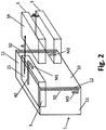
- FIG. 2 shows another example.
- the working and / or functional surface 20 completely as a stove plate 21, which is integrated in a body 3, formed.
- the stove plate 21 forms in a retracted state of the working and / or functional surface of a common plane with the kitchen top 2 from FIG. 1 ,
- the stove plate 21 can be pulled in the horizontal direction along arrow A from the kitchen block 10 forward from the access side and the front 10 of the furniture block 1 and then lowered in the vertical direction along arrow B, which is again shown by the dashed line.
- a linear guide 40 is provided, which is arranged on a perpendicular to the access side 10 of the furniture block 1 aligned side surface 11 of the furniture block 1 and one of the side surface 11 opposite side 34 of the body 3.
- linear guides 50 are arranged.
- a motor M1 which drives the horizontal linear guide 40 via a spindle, is provided. Accordingly, for lowering and raising the hearth plate 21, the motors M2 and M3 are provided which drive the vertical linear guides 50 via spindles.
- the control of the motors M1, M2, M3 can be done via a remote control. Thanks to the motors M1, M2 and M3, the stove plate 21 can also be fixed in any position.
- FIG. 3 shows a further embodiment, wherein in turn serves as a holding element, a body 3, in which a stove plate 21 is inserted.
- a support arm 6 which includes a lower member 60 and an upper member 62 connected via a hinge 61 to the lower member 60.
- the support arm is fixed by means of joints 63, 64 on a side facing the access side 10 of the furniture block 1 side 11 of the furniture block 1 and on the side 34 of the body 3.
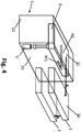
- FIG. 4 shows a further embodiment of the furniture according to the invention, wherein the drive device includes a combination of linear guide 40 and support arm 7.
- the linear guide 40 which is provided for the movement in the horizontal direction (arrow 4), is according to the example of FIG. 2 arranged laterally of the body 3 and the furniture block 10 and is moved by means of the motor M1 in the direction of the arrow A.
- a telescopic support arm 7 is provided, which extends along the side edge 12 of the access side 10 of the furniture block 1.
- the telescopic support arm is motor driven.
- FIG. 5A shows a kitchenette with a plurality of conventional furniture blocks 1 ', wherein the furniture blocks 1' are covered by a countertop 2. Between two adjacent furniture blocks 1 'a niche 0 is provided, in which there is a drive device.
- the drive device is in the form of a horizontal linear guide 40 which is fixed to the upper edge 13 of at least one of the furniture blocks 1 ', and a vertical linear guide 50 which is arranged on a side edge 12 of at least one furniture block 1' formed.
- the linear guide 40 is provided with a holding member 8 on which a kitchen plate portion 22 which overlaps the two adjacent furniture blocks 1 'is fixed. With the help of the linear motors M4 and M5, the kitchen plate portion 22 can be pulled out of the kitchen and lowered, as in Fig. 5B is shown.
- linear guides and a carrier arm or a combination of linear guide and carrier arm can be used as a drive device.
- a combined movement of horizontal and vertical movement can be realized, so that, if space permits so also oblique movements are possible.
- the present invention enables a simplification of the living conditions of wheelchair users and short people by the worktop or functional surface is suitably adapted to the size of the user and also below the work surface remains a free space that can be driven under without losing valuable storage space.
Landscapes
- Engineering & Computer Science (AREA)
- Chemical & Material Sciences (AREA)
- Combustion & Propulsion (AREA)
- Mechanical Engineering (AREA)
- General Engineering & Computer Science (AREA)
- Life Sciences & Earth Sciences (AREA)
- Sustainable Development (AREA)
- Combinations Of Kitchen Furniture (AREA)
- Drawers Of Furniture (AREA)
Description
- Die vorliegende Erfindung betrifft ein Küchenmöbel mit einer Arbeits- und/oder Funktionsfläche, in die mindestens eine Herdplatte integriert ist.
- In der industrialisierten Welt können viele Güter zu sehr günstigen Preisen hergestellt werden, da sie in großen Stückzahlen gefertigt werden. Dies hat jedoch den Nachteil, dass die entsprechenden Gerätschaften keinen individuellen Charakter aufweisen und an Standardbedürfnisse angepasst sind. Dies ist jedoch für bestimmte Bevölkerungsgruppen nachteilig, da sie bei den entsprechenden Standardbedingungen benachteiligt oder gehandicapt sind, wie beispielsweise körperlich behinderte oder kleinwüchsigen Menschen. So ist es beispielsweise für Rollstuhlfahrer schwierig, standardisierte Geräte zu nutzen, da diese auf Menschen ohne körperliche Behinderung zugeschnitten sind.
- Dies gilt insbesondere auch für Möbel, die in großen Stückzahlen standardisiert hergestellt werden. Derartige Möbel sind ebenfalls auf die Nutzung durch körperlich nicht behinderte Menschen ausgerichtet, sodass körperlich behinderte Menschen, wie beispielsweise Rollstuhlfahrer, diese Möbel nicht oder nur eingeschränkt nutzen können.
- Aus dem Stand der Technik sind deshalb bereits Möbel bekannt, die auf spezielle Bedürfnisse für Behinderte zugeschnitten sind. Ein Beispiel ist durch einen Schrank gegeben, wie er beispielsweise in der
DE 10 2010 005 024.5 beschrieben ist, in der ein Schrank gezeigt ist, bei dem die oberen Ablagefächer durch einen Mechanismus aus dem Schrank ausfahrbar und vor der Vorderseite des Schranks absenkbar sind, sodass Rollstuhlfahrer die Ablagefächer errei-chen können. - Obwohl damit für Menschen mit körperlicher Behinderung bereits ein geeignetes Hilfsmittel gegeben ist, besteht jedoch weiterhin Bedarf, die Lebensqualität von körperlich behinderten Menschen durch Bereitstellen von geeigneten Möbeln zu verbessern.
- Das Dokument
DE 101 59 649 A1 offenbart ferner eine Anordnung mit einer Kochmulde, die an einer Küchenarbeitsplatte gehaltert ist und zwischen einer Verwahrposition und einer Gebrauchsposition verstellbar ist, wobei die Kochmulde in der Verwahrposition unterhalb der Küchenarbeitsplatte angeordnet und nicht verwendbar ist und in der Gebrauchsposition oberhalb der Küchenarbeitsplatte angeordnet ist. Damit wird bei diesem Gegenstand nicht bewirkt, dass die Kochmulde für behinderte Personen leichter erreichbar ist, sondern es wird nur erreicht, dass bei Nicht - Gebrauch der Kochmulde der Platz anderweitig zur Verfügung steht. - Es ist somit Aufgabe der vorliegenden Erfindung, ein Möbel bereitzustellen, welche für körperlich Behinderte und insbesondere Rollstuhlfahrer geeignet ist und es den körperlich behinderten Menschen bzw. Rollstuhlfahrern ermöglicht, das Möbel vollständig zu nutzen. Gleichzeitig soll das entsprechende Möbel einfach aufgebaut und bedienbar sein.
- Diese Aufgabe wird gelöst durch ein Küchenmöbel mit einer Arbeits- oder Funktionsfläche gemäß Anspruch 1. Vorteilhafte Ausgestaltungen der Erfindung sind Gegenstand der jeweiligen abhängigen Ansprüche.
- Die Erfindung geht aus von der Erkenntnis, dass für das selbständige Leben von körperlich behinderten Menschen die selbstständige Zubereitung von Lebensmitteln sehr bedeutsam ist. Allerdings sind gerade Küchenmöbel so gestaltet, dass sie von körperlich behinderten Menschen, wie Kleinwüchsigen oder Rollstuhlfahrern, nur schwer zu bedienen sind. Hier ist vor allem die Gestaltung und Anordnung von Herdplatten zu nennen, die üblicherweise in einer Arbeits- oder Funktionsfläche eines Küchenmöbels integriert sind. Unter Herdplatten werden hierbei sämtliche Geräte verstanden, die für eine Zubereitung von Speisen in einer Arbeits - oder Funktionsfläche geeignet sind, wie elektrische Heizfelder, Induktionsheizfelder, Gasheizfelder, Bratflächen, Grillflächen und dergleichen. Kleinwüchsige Menschen oder Rollstuhlfahrer haben hier die Schwierigkeit entfernt liegende Bereiche der Arbeits - und/oder Funktionsfläche zu erreichen, da sie üblicherweise nur von einer Seite zugänglich ist. Dieses Problem wird erfindungsgemäße dadurch gelöst, dass die Arbeits- oder Funktionsfläche, in die mindestens eine Herdplatte integriert ist und horizontal und vertikal bewegbar ausgebildet ist.
- Auf diese Weise kann die Arbeits - und/oder Funktionsfläche so angeordnet werden, dass sie für jedermann in allen Bereichen leicht zugänglich ist. Das erfindungsgemäße Küchenmöbel ermöglicht es somit, die Arbeits- und/oder Funktionsfläche horizontal, beispielsweise aus einer Küchenzeile, auszufahren und wahlweise auf eine für den Nutzer geeignete Höhe abzusenken. Hierzu ist eine Halte - und Antriebsvorrichtung vorgesehen, mit der die Arbeits - und/oder Funktionsfläche gehalten und bewegt wird.
- Die Bewegung der Arbeits - und/oder Funktionsfläche kann dabei so erfolgen, dass die Arbeits - und/oder Funktionsfläche in jeder Stellung der Halte - und Antriebsvorrichtung im Wesentlichen horizontal ausgerichtet ist.
- Die horizontale Bewegung entspricht dabei vorzugsweise einer Bewegung in einer horizontalen Ebene senkrecht zu einer Zugangsseite der Arbeits- und/oder Funktionsfläche bzw. des Möbels. Die vertikale Bewegung ist vorteilhafterweise eine Bewegung quer, insbesondere senkrecht zur horizontalen Ebene, insbesondere entlang der Zugangsseite der Arbeits- und/oder Funktionsfläche bzw. des Möbels.
- Das Küchenmöbel weist eine Vorderseite auf, die üblicherweise der Zugangsseite entspricht. Die Vorderseite ist durch die Front des Küchenmöbels oder im einfachsten Fall durch den Rand der Arbeits- und/oder Funktionsfläche an der primären Zugangsseite gebildet, auf die beispielsweise die Bedienelemente einer Herdplatte ausgerichtet sind. Die horizontale Bewegung der Arbeits- und/oder Funktionsfläche erfolgt in Richtung zur Zugangsseite und somit quer, insbesondere senkrecht zur Vorderseite, die auch dadurch definiert werden kann, dass dort weitere Öffnungen, Türen, Schübe und dergleichen angeordnet sein können, um von dieser Seite bedient zu werden.
- Die Arbeits- und/oder Funktionsfläche kann somit insbesondere über die Vorderseite hervorstehend und/oder vor der Vorderseite angeordnet werden.
- Insbesondere können die verschiedenen Bewegungsmöglichkeiten miteinander kombiniert werden, so dass sowohl eine horizontal als auch vertikale Bewegung möglich ist, und zwar sowohl gleichzeitig als auch hintereinander. So kann die Arbeits- und/oder Funktionsfläche vor die Vorderseite gefahren werden und dort auf und ab gefahren werden.
- Das erfindungsgemäße Möbel erlaubt es somit Arbeits- und/oder Funktionsflächen, die vorzugsweise an einer Oberseite eines Möbelblocks angeordnet sind und bei der Nutzung im Wesentlichen horizontal ausgerichtet sind, in horizontale Richtung senkrecht zur Zugangsseite aus dem Möbel herauszufahren und anschließend an der Zugangsseite des Möbel, insbesondere vor dem Möbelblock abzusenken. Damit lässt sich eine niedrigere Arbeitsfläche realisieren, bei der sämtliche Bereiche der Arbeits- bzw. Funktionsfläche für einen körperlich behinderten Menschen erreichbar sind und die zudem unterfahrbar ist.
- Durch die Kombination von Herausziehen bzw. Vorziehen vor die Zugangsseite des Möbelstücks und Absenken entlang des Möbelstücks kann die Arbeits- und/oder Funktionsfläche auch von drei Seiten zugänglich gemacht werden, sodass auch dadurch gegenüber einem reinen Absenken ein Vorteil hinsichtlich der Nutzbarkeit der Arbeits- oder Funktionsfläche gegeben ist.
- Zudem kann der Möbelkorpus unterhalb der Arbeits- und/oder Funktionsfläche als Schrank oder dergleichen eingesetzt werden, ohne den Zugang des Nutzers zur Arbeitsfläche einzuschränken.
- Zum Ausführen der horizontalen Bewegung kann die Antriebsvorrichtung mindestens eine horizontale Linearführung aufweisen. Alternativ oder zusätzlich kann die Antriebsvorrichtung zum Ausführen der vertikalen Bewegung des mindestens einen Halteelements weiterhin mindestens eine vertikale Linearführung ausweisen. Beispielsweise kann die Antriebsvorrichtung eine Kombination aus einer Mehrzahl an Linearführungen zusammengesetzt sein, wobei mindestens eine, vorzugsweise mehrere Linearführungen die horizontale Bewegung des Halteelementes ermöglichen, während mindestens eine, vorzugsweise zwei oder mehr Linearführungen für die vertikale Führung der Arbeits- und/oder Funktionsfläche verantwortlich sind.
- Die Linearführungen können Schienenanordnungen mit darin verfahrbaren Roll -, Gleit - oder Schiebeelementen aufweisen und vorzugsweise in Form von Rollen-, Schiebe- oder Gleitauszügen ausgebildet sein. Zusätzlich können die Linearführungen, insbesondere die vertikalen Linearführungen, zum Fixieren der Arbeits- und/oder Funktionsfläche in mindestens einer, vorzugsweise jeder beliebigen Stellung bzw. die Antriebsvorrichtung geeignete Gegengewichte und/oder Arretierungen und/oder Feststellvorrichtungen aufweisen. Damit ist es möglich, insbesondere die Höhe der Arbeitsfläche individuell an die Ansprüche und Bedürfnisse des Nutzers, insbesondere eines gehbehinderten oder eines kleinwüchsigen Menschen, anzupassen.
- Zum Ausführen der horizontalen Bewegung und/oder der vertikalen Bewegung kann die Antriebsvorrichtung alternativ oder zusätzlich mindestens einen Trägerarm aufweisen, der beispielsweise teleskopartig und/oder gelenkig ausgebildet sein kann. Vorzugsweise ist der Trägerarm unabhängig von seiner Gestaltung rotierbar angeordnet. Insbesondere ist der Trägerarm so konzipiert, dass eine horizontale Verschiebung und/oder eine vertikale Höhenverstellung bzw. eine kombinierte Bewegung der Arbeits- und/oder Funktionsfläche ermöglicht wird.
- Die Antriebsvorrichtung kann weiterhin eine Kombination aus mindestens einem Trägerarm und mindestens einer Linearführung enthalten. Beispielsweise kann die Linearführung für die horizontale Bewegung eingesetzt werden, während der Trägerarm für die vertikale Bewegung verantwortlich ist.
- Die Antriebsvorrichtung des Möbels kann sowohl manuell als auch motorbetrieben betätigt werden. Denkbar ist auch ein teilweise manueller und teilweise motorbetriebener Antrieb, wobei die Bewegung in horizontale Richtung beispielsweise manuell erfolgen kann, während die Bewegung in vertikale Richtung aufgrund der erhöhten Krafteinwirkung vorteilhafterweise motorbetrieben erfolgen kann.
- Der motorgetriebene Antrieb erfolgt vorteilhafterweise über mindestens einen Motor, insbesondere einen Elektromotor, und mindestens ein Spindel oder sonstige Linearantriebe. Alternativ oder zusätzlich kann die Antriebsvorrichtung auch einen Pneumatik- und/oder Hydraulikantrieb aufweisen. Bei Motorbetrieb kann gleichzeitig mit der Positionsveränderung auch eine gewünschte Positionsfixierung erreicht werden.
- Die Antriebsvorrichtung des Möbels kann, insbesondere sofern diese motorbetrieben ist, eine Steuereinheit oder eine Steuerbox aufweisen. Diese kann über einen Schalter und/oder über eine Fernsteuerung betätigt werden, wobei die Bewegung der Arbeits- und/oder Funktionsfläche in horizontale Richtung und die Bewegung in vertikale Richtung vorteilhafterweise getrennt steuerbar ist. Besonders vorteilhaft ist dabei eine Fernsteuerung, die einen Hebel oder Taster für die horizontale Bewegung und einen Hebel oder Taster für die vertikale Bewegung enthält oder einen entsprechenden Joystick.
- Das Möbel kann eine Halterung oder einen Rahmen umfassen, durch die die Arbeits- und/oder Funktionsfläche vorteilhafterweise über die Antriebsvorrichtung an einem Fußboden, an einer Wand und/oder zwischen zwei Möbeln befestigt sein kann. So kann beispielsweise eine Schiene einer Linearführung, die einen Teil der Antriebsvorrichtung bildet, an dem Möbel, insbesondere am Möbelblock befestigt, insbesondere angeschraubt oder angeklebt, sein. Weist die Antriebsvorrichtung einen oder mehrere Trägerarme auf, so können die Trägerarme über eine Halterung, die im Extremfall das Möbel bilden kann, am Fußboden oder an einer Wand und/oder an und/oder zwischen benachbarten Möbelblöcken befestigt sein. Außerdem kann es vorteilhaft sein, die Antriebsvorrichtung als stabilen motorbetriebenen teleskopartigen Trägerarm auszubilden, der zwischen zwei benachbarten Möbelblöcken angeordnet ist, so dass die Arbeits- und/oder Funktionsfläche z.B. in Form eines Küchenplattenabschnitts im eingefahrenen Zustand mit den benachbarten Möbelblöcken überlappt oder eine gemeinsame Arbeitsfläche mit diesen bildet.
- Das erfindungsgemäße Möbel weist weiterhin einen Möbelblock auf.
- Der Möbelblock kann beispielsweise als Unterschrank mit Einlegeböden und/oder Schubladen ausgebildet sein. Unabhängig von der speziellen Ausformung des Möbelblocks kann dieser an seiner Zugangsseite eine Ausnehmung aufweisen, um die Unterfahrbarkeit zu verbessern.
- Bei dem Möbel kann ein Sensor vorgesehen sein, der bestimmt, dass sofern mindestens eine der Herdplatten eingeschaltet ist oder mit Kochgeschirr, insbesondere heißem Kochgeschirr, belegt ist, eine weitere Bewegung der Antriebsvorrichtung ausbleibt. Alternativ oder zusätzlich kann eine Vorrichtung auf die Herdplatten gesetzt sein, die das Verrutschen von Kochgeschirr beim Bewegen der Arbeits- und/oder Funktionsplatte verhindert. Eine solche Vorrichtung kann beispielsweise ein Korb aus Silikon oder Aluminium sein, der an der Arbeits- und/oder Funktionsfläche befestigt ist.
- Durch das vorgestellte Möbel wird für Rollstuhlfahrern und kleinwüchsigen Menschen die Arbeit im Haushalt erleichtert und Unfälle bei der Hausarbeit vermieden. Dies wird dadurch erreicht, dass insbesondere die Höhe der Arbeits- und/oder Funktionsfläche verstellbar ist, ohne dabei Stauraum zu verlieren und gleichzeitig die Unterfahrbarkeit der Arbeits- und/oder Funktionsfläche gewährleistet wird, so dass der Nutzer sämtliche Bereiche der Arbeitsplatte problemlos erreichen kann.
- Die vorliegende Erfindung wird nachfolgend anhand von Figuren und Ausführungsbeispielen weiter erläutert. Die Zeichnungen zeigen dabei in rein schematischer Weise in
- Fig. 1
- eine erste Ausführungsform eines erfindungsgemäßen Möbels;
- Fig. 2
- eine zweite Ausführungsform eines erfindungsgemäßen Möbels mit Linearführungen als Antriebsvorrichtung;
- Fig. 3
- eine dritte Ausführungsform eines erfindungsgemäßen Möbels mit einem Trägerarm als Antriebsvorrichtung;
- Fig. 4
- eine vierte Ausführungsform eines erfindungsgemäßen Möbels mit einer Kombination aus Linearführung und Trägerarm als Antriebsvorrichtung; und in
- Fig. 5 A und B
- eine fünfte Ausführungsform eines erfindungsgemäßen Möbels zum Anbringen zwischen zwei Möbelblöcken.
- Weitere Vorteile, Kennzeichen und Merkmale der vorliegenden Erfindung werden bei der nachfolgenden detaillierten Beschreibung der Ausführungsbeispiele deutlich, wobei die Erfindung jedoch nicht auf diese Ausführungsbeispiele beschränkt ist.
-
Figur 1 zeigt eine Küchenzeile aus einer Mehrzahl an herkömmlichen Unterschränken (nicht gezeigt), einem quaderförmigen Möbelblock 1 und einer an den Möbelblock 1 angrenzenden fest installierten Arbeitsplatte 2. Der Möbelblock 1 weist an seiner Oberseite eine verfahrbare Arbeits- und/oder Funktionsfläche 20 auf, die in einem als quaderförmiger Korpus 3 ausgebildeten Halteelement aufgenommen ist. Der quaderförmige Korpus 3 kann in Richtung der Vorderseite bzw. Zugangsseite 10 des Möbelblocks 1 bzw. der Küchenzeile, also der Seite, an der üblicherweise an die Arbeits- und/oder Funktionsfläche 20 herangetreten wird, herausbewegt werden und dann anschließend entlang der Vorderseite 10 des Möbelblocks 1 abgesenkt werden, wie durch die strichlinierte Darstellung des quaderförmigen Korpus 3 gezeigt ist. Entsprechend umfasst der Korpus 3 beispielsweise an seinen Kanten 30 an der Unterseite 31 lineare Auszüge 32 zum Ausziehen des Korpus 3 aus dem Möbelblock 1 sowie an der Vorderseite 10 des Möbelblocks 1 Linearführungen 50 für ein Absenken. Die Arbeits- und/oder Funktionsfläche 20 kann in jeder ausgezogenen Position und jeder Höhenposition fixiert werden. -
Figur 2 zeigt ein weiteres Beispiel. Bei dem Beispiel derFigur 2 ist die Arbeits- und/oder Funktionsfläche 20 vollständig als Herdplatte 21, die in einem Korpus 3 integriert ist, ausgebildet. Die Herdplatte 21 bildet in einem eingefahrenen Zustand der Arbeits- und/oder Funktionsfläche eine gemeinsame Ebene mit der Küchenplatte 2 ausFigur 1 . Die Herdplatte 21 kann in horizontale Richtung entlang Pfeil A aus dem Küchenblock 10 nach vorne aus der Zugangsseite bzw. der Vorderseite 10 des Möbelblocks 1 ausgezogen und anschließend in vertikale Richtung entlang Pfeil B abgesenkt werden, was wieder durch die strichlinierte Darstellung gezeigt ist. Zum Ausziehen der Herdplatte 21 in Richtung des Pfeils A ist eine Linearführung 40 vorgesehen, die an einer senkrecht zur Zugangsseite 10 des Möbelblocks 1 ausgerichteten Seitenfläche 11 des Möbelblocks 1 und einer der Seitenfläche 11 gegenüberliegenden Seite 34 des Korpus 3 angeordnet ist. Zum Absenken der Herdplatte 21 sowie des Korpus 3 sind beidseitig an den vertikalen Kanten 12 der Zugangs seite 10 des Möbelblocks 1 Linearführungen 50 angeordnet. - Zum Ausziehen und Einziehen der Herdplatte 21 aus bzw. in die Küchenzeile ist ein Motor M1, der die horizontale Linearführung 40 über eine Spindel antreibt, vorgesehen. Entsprechend sind zum Absenken und Anheben der Herdplatte 21 die Motoren M2 und M3 vorgesehen, die die vertikalen Linearführungen 50 über Spindeln antreiben. Die Steuerung der Motoren M1, M2, M3 kann über eine Fernbedienung erfolgen. Dank der Motoren M1, M2 und M3 kann die Herdplatte 21 zudem in jeder beliebigen Position fixiert werden.
-
Figur 3 zeigt ein weiteres Ausführungsbeispiel, wobei als Halteelement wiederum ein Korpus 3 dient, in den eine Herdplatte 21 eingelegt ist. Als Antriebsvorrichtung dient im Beispiel derFigur 3 ein Trägerarm 6, der ein unteres Glied 60 und ein über ein Gelenk 61 mit dem unteren Glied 60 verbundenes oberes Glied 62 enthält. Der Trägerarm ist mittels Gelenken 63, 64 an einer zu der Zugangs seite 10 des Möbelblocks 1 senkrecht angeordneten Seite 11 des Möbelblocks 1 sowie an der Seite 34 des Korpus 3 befestigt ist. Wie durch die Strichliniendarstellung gezeigt, erfolgt die Bewegung des Korpus 3 in die horizontale Richtung (Pfeil A) und vertikaler Richtung (Pfeil B) durch Drehung des Trägerarms 6 um das Gelenk 63 am Möbelblock 1 und gleichzeitiges Verändern des Winkels zwischen dem unteren und dem oberen Glied 60, 62 des Trägerarms 6. - Die
Figur 4 zeigt ein weiteres Ausführungsbeispiel des erfindungsgemäßen Möbels, wobei die Antriebsvorrichtung eine Kombination aus Linearführung 40 und Trägerarm 7 enthält. Die Linearführung 40, die für die Bewegung in horizontale Richtung (Pfeil 4) vorgesehen ist, ist entsprechend dem Beispiel derFigur 2 seitlich des Korpus 3 sowie des Möbelblocks 10 angeordnet und wird mit Hilfe des Motors M1 in Richtung des Pfeils A bewegt. Für die Absenk- bzw. Hebebewegung parallel zur Richtung des Pfeils B ist ein teleskopartiger Trägerarm 7 vorgesehen, der sich entlang der Seitenkante 12 der Zugangsseite 10 des Möbelblocks 1 erstreckt. Der teleskopartige Trägerarm ist dabei motorbetrieben. - Die
Figur 5A zeigt eine Küchenzeile mit einer Mehrzahl an konventionellen Möbelblöcken 1', wobei die Möbelblöcke 1' von einer Arbeitsplatte 2 bedeckt sind. Zwischen zwei benachbarten Möbelblöcken 1' ist eine Nische 0 vorgesehen, in der sich eine Antriebsvorrichtung befindet. Die Antriebsvorrichtung ist in Form einer horizontalen Linearführung 40, die an der Oberkante 13 mindestens eines der Möbelblöcke 1' befestigt ist, und einer vertikalen Linearführung 50, die an einer Seitenkante 12 mindestens eines Möbelblocks 1'angeordnet ist, ausgebildet. Die Linearführung 40 ist mit einem Halteelement 8 versehen, auf dem ein Küchenplattenabschnitt 22, der die beiden benachbarten Möbelblöcke 1' überlappt, befestigt ist. Mit Hilfe der Linearmotoren M4 und M5 kann der Küchenplattenabschnitt 22 aus der Küchenzeile herausgezogen werden und abgesenkt werden, wie inFig. 5B gezeigt ist. - Anstelle der Linearführungen kann auch ein Trägerarm oder eine Kombination aus Linearführung und Trägerarm als Antriebsvorrichtung zum Einsatz kommen. Insbesondere kann auch eine kombinierte Bewegung aus horizontaler und vertikaler Bewegung realisiert werden, so dass, wenn die Platzverhältnisse dies erlauben auch schräge Bewegungen möglich sind.
- Wie durch die Figuren weiter verdeutlicht, ermöglicht die vorliegende Erfindung eine Vereinfachung der Lebensumstände von Rollstuhlfahrern und kleinwüchsigen Personen, indem die Arbeitsplatte bzw. Funktionsfläche in geeigneter Weise an die Größe der Nutzer anpassbar ist und zudem unterhalb der Arbeitsfläche ein Freiraum bleibt, der unterfahren werden kann, ohne dass wertvoller Stauraum verloren geht.
Claims (7)
- Küchenmöbel mit einem quaderförmigen Möbelblocks (1) und einer an den Möbelblock (1) angrenzenden fest installierten Küchenarbeitsplatte (2), wobei das Küchenmöbel eine Vorderseite und eine Arbeits- und/oder Funktionsfläche (20) aufweist, in die mindestens eine Herdplatte (21) integriert ist,
wobei das Küchenmöbel eine Halte - und Antriebsvorrichtung umfasst, in der die Arbeits- und/oder Funktionsfläche (20) gelagert ist und mit der die Arbeits- und/oder Funktionsfläche (20) horizontal und vertikal bewegbar ist, wobei die Ar-beits- und/oder Funktionsfläche (20) im ausgefahrenen Zustand vor der Vordersei-te angeordnet ist und dann anschließend entlang der Vorderseite absenkbar ist,
dadurch gekennzeichnet, dass
die Herdplatten (21) im eingefahrenen Zustand der Arbeits- und/oder Funktionsfläche (20) an einer Oberseite des Möbelblocks (1) angeordnet ist, sodass eine gemeinsame Ebene mit der Küchenarbeitsplatte (2) ausgebildet ist. - Küchenmöbel nach Anspruch 1,
dadurch gekenntzeichnet, dass
die Halte - und Antriebsvorrichtung so ausgebildet ist, dass die Arbeits- und/oder Funktionsfläche (20) in jeder Stellung der Antriebsvorrichtung (6, 7, 40, 50) horizontal ausgerichtet ist. - Küchenmöbel nach einem der vorhergehenden Ansprüche,
dadurch gekennzeichnet, dass
die Halte - und Antriebsvorrichtung (3, 6, 7, 8, 40, 50) zum Ausführen der horizontalen Bewegung und/oder der vertikalen Bewegung der Arbeits- und/oder Funktionsfläche (20) mindestens eine Linearführung (40, 50) für eine lineare Bewegung, insbesondere in Form einer Schienenanordnung mit Rollen -, Gleit - oder Schiebeelementen, die in der Schienenanordnung bewegbar sind, vorzugsweise in Form eines Rollen-, Schiebe- oder Gleitauszugs, aufweist. - Küchenmöbel einem der vorhergehenden Ansprüche,
dadurch gekennzeichnet, dass
die Halte - und Antriebsvorrichtung (3, 6, 7, 8, 0, 50) zum Ausführen der horizontalen Bewegung und/oder der vertikalen Bewegung der Arbeits- und/oder Funktionsfläche (20) mindestens einen beweglichen Trägerarm (6, 7) aufweist, der insbesondere teleskopartig und/oder gelenkig ausgebildet ist und/oder verschwenkbar angeordnet ist. - Küchenmöbel nach einem der vorhergehenden Ansprüche,
dadurch gekennzeichnet, dass
die Halte - und Antriebsvorrichtung (3, 6, 7, 8, 40, 50) so hergerichtet ist, dass die Arbeits- und/oder Funktionsfläche in mehreren Positionen, insbesondere in jeder Position entlang eines Verfahrwegs der horizontalen und/oder der vertikalen Bewegung fixiert werden kann. - Küchenmöbel nach einem der vorhergehenden Ansprüche,
dadurch gekennzeichnet, dass
die Halte - und Antriebsvorrichtung (3, 6, 7, 8, 40, 50) zum Ausführen der horizontalen und/oder vertikalen Bewegung der Arbeits- und/oder Funktionsfläche (20) einen motorgetriebenen Antrieb, insbesondere einen Spindelantrieb, und/oder einen Pneumatikantrieb und/oder einen Hydraulikantrieb aufweist. - Küchenmöbel nach dem vorhergehenden Anspruch,
dadurch gekennzeichnet, dass
die Halte - und Antriebsvorrichtung (3, 6, 7, 8, 40, 50) eine Fernsteuerung umfasst.
Applications Claiming Priority (1)
| Application Number | Priority Date | Filing Date | Title |
|---|---|---|---|
| DE201310102174 DE102013102174A1 (de) | 2013-03-05 | 2013-03-05 | Küchenmöbel mit verfahrbarer Arbeitsplatte |
Publications (3)
| Publication Number | Publication Date |
|---|---|
| EP2786674A2 EP2786674A2 (de) | 2014-10-08 |
| EP2786674A3 EP2786674A3 (de) | 2014-10-22 |
| EP2786674B1 true EP2786674B1 (de) | 2017-04-12 |
Family
ID=50193307
Family Applications (1)
| Application Number | Title | Priority Date | Filing Date |
|---|---|---|---|
| EP14157381.6A Active EP2786674B1 (de) | 2013-03-05 | 2014-02-28 | Küchenmöbel mit verfahrbarer Arbeitsplatte |
Country Status (2)
| Country | Link |
|---|---|
| EP (1) | EP2786674B1 (de) |
| DE (1) | DE102013102174A1 (de) |
Cited By (1)
| Publication number | Priority date | Publication date | Assignee | Title |
|---|---|---|---|---|
| DE202017004670U1 (de) | 2017-09-07 | 2017-09-21 | Helmut Pracht | Multifunktionales Koch- und Tischmöbelstück |
Families Citing this family (2)
| Publication number | Priority date | Publication date | Assignee | Title |
|---|---|---|---|---|
| CN112056814A (zh) * | 2020-09-17 | 2020-12-11 | 宜兴慕森智能家居有限公司 | 餐边柜 |
| CN117091167A (zh) * | 2023-09-06 | 2023-11-21 | 浙江亿田智能厨电股份有限公司 | 集成灶及集成灶的控制方法 |
Family Cites Families (5)
| Publication number | Priority date | Publication date | Assignee | Title |
|---|---|---|---|---|
| JP2001269236A (ja) * | 2000-03-24 | 2001-10-02 | Matsushita Electric Ind Co Ltd | 昇降式調理機器 |
| DE10159649A1 (de) * | 2001-12-05 | 2003-06-18 | Bsh Bosch Siemens Hausgeraete | Anordnung mit einer Kochmulde und einer Küchenarbeitsplatte sowie Kochmulde |
| WO2008114426A1 (ja) * | 2007-03-20 | 2008-09-25 | Yuko Tsushima | システムキッチン |
| DE102010005024B4 (de) | 2010-01-20 | 2015-11-19 | Manfred Philipp | Hochschrank mit fahrbarem Schubkasten |
| ITTO20100298A1 (it) * | 2010-04-14 | 2011-10-15 | Indesit Co Spa | Apparecchio di cottura domestico |
-
2013
- 2013-03-05 DE DE201310102174 patent/DE102013102174A1/de not_active Withdrawn
-
2014
- 2014-02-28 EP EP14157381.6A patent/EP2786674B1/de active Active
Non-Patent Citations (1)
| Title |
|---|
| None * |
Cited By (1)
| Publication number | Priority date | Publication date | Assignee | Title |
|---|---|---|---|---|
| DE202017004670U1 (de) | 2017-09-07 | 2017-09-21 | Helmut Pracht | Multifunktionales Koch- und Tischmöbelstück |
Also Published As
| Publication number | Publication date |
|---|---|
| EP2786674A3 (de) | 2014-10-22 |
| EP2786674A2 (de) | 2014-10-08 |
| DE102013102174A1 (de) | 2014-09-11 |
Similar Documents
| Publication | Publication Date | Title |
|---|---|---|
| EP0107162B1 (de) | Arbeitstisch | |
| EP2702219A1 (de) | Möbel mit einem möbelkorpus und einer faltklappe | |
| EP2786674A2 (de) | Küchenmöbel mit verfahrbarer Arbeitsplatte | |
| DE202017004670U1 (de) | Multifunktionales Koch- und Tischmöbelstück | |
| DE4001382C2 (de) | ||
| DE102016107109A1 (de) | Kücheneinbaugerät und Verfahren zum Betreiben | |
| EP2983553A1 (de) | Auszugsvorrichtung für schrankauszüge | |
| DE102011007471A1 (de) | Bedienelement für ein Haushaltsgerät und Haushaltsgerät | |
| EP3363324B1 (de) | Küche | |
| DE102015119322B4 (de) | Vorrichtung zur Absaugung von Kochdünsten | |
| DE102017204238B4 (de) | Kochvorrichtung mit einem Kochfeld und Anordnung einer Kochvorrichtung | |
| DE19543113A1 (de) | Dunstabzugshaube für eine Haushaltsküche | |
| DE3731869A1 (de) | Anordnung fuer einrichtungen mit schraenken | |
| EP3029383B1 (de) | Dunstabzugshaube | |
| EP1972228B1 (de) | Möbel zur Aufnahme von Arbeitsmaterialien und/oder -geräten für Labor- oder Unterichtsräume und Tischgestell zur Aufnahme eines Fachbodens aus einem derartigen Möbel | |
| DE10159649A1 (de) | Anordnung mit einer Kochmulde und einer Küchenarbeitsplatte sowie Kochmulde | |
| DE10052240B4 (de) | Anordnung von verschiebbaren Flächenelementen einer Möbelfront | |
| DE10124316B4 (de) | Säule für höhenverstellbare Möbelelemente | |
| DE102017223720A1 (de) | Kochfeld-Vorrichtung | |
| EP2849608B1 (de) | Möbelmodul | |
| DE102012109334A1 (de) | Hubsystem für ein höhenverstellbares Arbeitsplatzsystem und Arbeitsplatzsystem mit einem solchen Hubsystem | |
| DE4332706C2 (de) | Arbeitsplatz | |
| DE29807238U1 (de) | Einbauküche und Hängeschrank | |
| DE3308032A1 (de) | Kochherd | |
| DE10207281B4 (de) | Standhaushaltsgerät |
Legal Events
| Date | Code | Title | Description |
|---|---|---|---|
| PUAL | Search report despatched |
Free format text: ORIGINAL CODE: 0009013 |
|
| PUAI | Public reference made under article 153(3) epc to a published international application that has entered the european phase |
Free format text: ORIGINAL CODE: 0009012 |
|
| 17P | Request for examination filed |
Effective date: 20140228 |
|
| AK | Designated contracting states |
Kind code of ref document: A2 Designated state(s): AL AT BE BG CH CY CZ DE DK EE ES FI FR GB GR HR HU IE IS IT LI LT LU LV MC MK MT NL NO PL PT RO RS SE SI SK SM TR |
|
| AX | Request for extension of the european patent |
Extension state: BA ME |
|
| AK | Designated contracting states |
Kind code of ref document: A3 Designated state(s): AL AT BE BG CH CY CZ DE DK EE ES FI FR GB GR HR HU IE IS IT LI LT LU LV MC MK MT NL NO PL PT RO RS SE SI SK SM TR |
|
| AX | Request for extension of the european patent |
Extension state: BA ME |
|
| RIC1 | Information provided on ipc code assigned before grant |
Ipc: A47B 77/08 20060101AFI20140915BHEP Ipc: A47B 77/12 20060101ALI20140915BHEP Ipc: F24C 15/30 20060101ALI20140915BHEP |
|
| R17P | Request for examination filed (corrected) |
Effective date: 20150423 |
|
| RBV | Designated contracting states (corrected) |
Designated state(s): AL AT BE BG CH CY CZ DE DK EE ES FI FR GB GR HR HU IE IS IT LI LT LU LV MC MK MT NL NO PL PT RO RS SE SI SK SM TR |
|
| 17Q | First examination report despatched |
Effective date: 20151204 |
|
| GRAP | Despatch of communication of intention to grant a patent |
Free format text: ORIGINAL CODE: EPIDOSNIGR1 |
|
| INTG | Intention to grant announced |
Effective date: 20160921 |
|
| GRAS | Grant fee paid |
Free format text: ORIGINAL CODE: EPIDOSNIGR3 |
|
| GRAA | (expected) grant |
Free format text: ORIGINAL CODE: 0009210 |
|
| AK | Designated contracting states |
Kind code of ref document: B1 Designated state(s): AL AT BE BG CH CY CZ DE DK EE ES FI FR GB GR HR HU IE IS IT LI LT LU LV MC MK MT NL NO PL PT RO RS SE SI SK SM TR |
|
| REG | Reference to a national code |
Ref country code: GB Ref legal event code: FG4D Free format text: NOT ENGLISH |
|
| REG | Reference to a national code |
Ref country code: CH Ref legal event code: EP |
|
| REG | Reference to a national code |
Ref country code: IE Ref legal event code: FG4D Free format text: LANGUAGE OF EP DOCUMENT: GERMAN |
|
| REG | Reference to a national code |
Ref country code: AT Ref legal event code: REF Ref document number: 883020 Country of ref document: AT Kind code of ref document: T Effective date: 20170515 |
|
| REG | Reference to a national code |
Ref country code: DE Ref legal event code: R096 Ref document number: 502014003351 Country of ref document: DE |
|
| REG | Reference to a national code |
Ref country code: NL Ref legal event code: MP Effective date: 20170412 |
|
| REG | Reference to a national code |
Ref country code: LT Ref legal event code: MG4D |
|
| PG25 | Lapsed in a contracting state [announced via postgrant information from national office to epo] |
Ref country code: NL Free format text: LAPSE BECAUSE OF FAILURE TO SUBMIT A TRANSLATION OF THE DESCRIPTION OR TO PAY THE FEE WITHIN THE PRESCRIBED TIME-LIMIT Effective date: 20170412 |
|
| REG | Reference to a national code |
Ref country code: CH Ref legal event code: NV Representative=s name: LANGPATENT ANWALTSKANZLEI IP LAW FIRM, CH |
|
| PG25 | Lapsed in a contracting state [announced via postgrant information from national office to epo] |
Ref country code: GR Free format text: LAPSE BECAUSE OF FAILURE TO SUBMIT A TRANSLATION OF THE DESCRIPTION OR TO PAY THE FEE WITHIN THE PRESCRIBED TIME-LIMIT Effective date: 20170713 Ref country code: ES Free format text: LAPSE BECAUSE OF FAILURE TO SUBMIT A TRANSLATION OF THE DESCRIPTION OR TO PAY THE FEE WITHIN THE PRESCRIBED TIME-LIMIT Effective date: 20170412 Ref country code: HR Free format text: LAPSE BECAUSE OF FAILURE TO SUBMIT A TRANSLATION OF THE DESCRIPTION OR TO PAY THE FEE WITHIN THE PRESCRIBED TIME-LIMIT Effective date: 20170412 Ref country code: LT Free format text: LAPSE BECAUSE OF FAILURE TO SUBMIT A TRANSLATION OF THE DESCRIPTION OR TO PAY THE FEE WITHIN THE PRESCRIBED TIME-LIMIT Effective date: 20170412 Ref country code: NO Free format text: LAPSE BECAUSE OF FAILURE TO SUBMIT A TRANSLATION OF THE DESCRIPTION OR TO PAY THE FEE WITHIN THE PRESCRIBED TIME-LIMIT Effective date: 20170712 Ref country code: FI Free format text: LAPSE BECAUSE OF FAILURE TO SUBMIT A TRANSLATION OF THE DESCRIPTION OR TO PAY THE FEE WITHIN THE PRESCRIBED TIME-LIMIT Effective date: 20170412 |
|
| PG25 | Lapsed in a contracting state [announced via postgrant information from national office to epo] |
Ref country code: PL Free format text: LAPSE BECAUSE OF FAILURE TO SUBMIT A TRANSLATION OF THE DESCRIPTION OR TO PAY THE FEE WITHIN THE PRESCRIBED TIME-LIMIT Effective date: 20170412 Ref country code: IS Free format text: LAPSE BECAUSE OF FAILURE TO SUBMIT A TRANSLATION OF THE DESCRIPTION OR TO PAY THE FEE WITHIN THE PRESCRIBED TIME-LIMIT Effective date: 20170812 Ref country code: BG Free format text: LAPSE BECAUSE OF FAILURE TO SUBMIT A TRANSLATION OF THE DESCRIPTION OR TO PAY THE FEE WITHIN THE PRESCRIBED TIME-LIMIT Effective date: 20170712 Ref country code: LV Free format text: LAPSE BECAUSE OF FAILURE TO SUBMIT A TRANSLATION OF THE DESCRIPTION OR TO PAY THE FEE WITHIN THE PRESCRIBED TIME-LIMIT Effective date: 20170412 Ref country code: SE Free format text: LAPSE BECAUSE OF FAILURE TO SUBMIT A TRANSLATION OF THE DESCRIPTION OR TO PAY THE FEE WITHIN THE PRESCRIBED TIME-LIMIT Effective date: 20170412 Ref country code: RS Free format text: LAPSE BECAUSE OF FAILURE TO SUBMIT A TRANSLATION OF THE DESCRIPTION OR TO PAY THE FEE WITHIN THE PRESCRIBED TIME-LIMIT Effective date: 20170412 |
|
| REG | Reference to a national code |
Ref country code: DE Ref legal event code: R097 Ref document number: 502014003351 Country of ref document: DE |
|
| PG25 | Lapsed in a contracting state [announced via postgrant information from national office to epo] |
Ref country code: SK Free format text: LAPSE BECAUSE OF FAILURE TO SUBMIT A TRANSLATION OF THE DESCRIPTION OR TO PAY THE FEE WITHIN THE PRESCRIBED TIME-LIMIT Effective date: 20170412 Ref country code: EE Free format text: LAPSE BECAUSE OF FAILURE TO SUBMIT A TRANSLATION OF THE DESCRIPTION OR TO PAY THE FEE WITHIN THE PRESCRIBED TIME-LIMIT Effective date: 20170412 Ref country code: CZ Free format text: LAPSE BECAUSE OF FAILURE TO SUBMIT A TRANSLATION OF THE DESCRIPTION OR TO PAY THE FEE WITHIN THE PRESCRIBED TIME-LIMIT Effective date: 20170412 Ref country code: RO Free format text: LAPSE BECAUSE OF FAILURE TO SUBMIT A TRANSLATION OF THE DESCRIPTION OR TO PAY THE FEE WITHIN THE PRESCRIBED TIME-LIMIT Effective date: 20170412 Ref country code: DK Free format text: LAPSE BECAUSE OF FAILURE TO SUBMIT A TRANSLATION OF THE DESCRIPTION OR TO PAY THE FEE WITHIN THE PRESCRIBED TIME-LIMIT Effective date: 20170412 |
|
| PLBE | No opposition filed within time limit |
Free format text: ORIGINAL CODE: 0009261 |
|
| STAA | Information on the status of an ep patent application or granted ep patent |
Free format text: STATUS: NO OPPOSITION FILED WITHIN TIME LIMIT |
|
| PG25 | Lapsed in a contracting state [announced via postgrant information from national office to epo] |
Ref country code: SM Free format text: LAPSE BECAUSE OF FAILURE TO SUBMIT A TRANSLATION OF THE DESCRIPTION OR TO PAY THE FEE WITHIN THE PRESCRIBED TIME-LIMIT Effective date: 20170412 Ref country code: IT Free format text: LAPSE BECAUSE OF FAILURE TO SUBMIT A TRANSLATION OF THE DESCRIPTION OR TO PAY THE FEE WITHIN THE PRESCRIBED TIME-LIMIT Effective date: 20170412 |
|
| REG | Reference to a national code |
Ref country code: DE Ref legal event code: R082 Ref document number: 502014003351 Country of ref document: DE Representative=s name: DIE PATENTERIE GBR PATENT- UND RECHTSANWALTSSO, DE |
|
| 26N | No opposition filed |
Effective date: 20180115 |
|
| PG25 | Lapsed in a contracting state [announced via postgrant information from national office to epo] |
Ref country code: SI Free format text: LAPSE BECAUSE OF FAILURE TO SUBMIT A TRANSLATION OF THE DESCRIPTION OR TO PAY THE FEE WITHIN THE PRESCRIBED TIME-LIMIT Effective date: 20170412 |
|
| REG | Reference to a national code |
Ref country code: CH Ref legal event code: PL |
|
| PG25 | Lapsed in a contracting state [announced via postgrant information from national office to epo] |
Ref country code: MT Free format text: LAPSE BECAUSE OF FAILURE TO SUBMIT A TRANSLATION OF THE DESCRIPTION OR TO PAY THE FEE WITHIN THE PRESCRIBED TIME-LIMIT Effective date: 20170412 Ref country code: MC Free format text: LAPSE BECAUSE OF FAILURE TO SUBMIT A TRANSLATION OF THE DESCRIPTION OR TO PAY THE FEE WITHIN THE PRESCRIBED TIME-LIMIT Effective date: 20170412 |
|
| GBPC | Gb: european patent ceased through non-payment of renewal fee |
Effective date: 20180228 |
|
| REG | Reference to a national code |
Ref country code: IE Ref legal event code: MM4A |
|
| REG | Reference to a national code |
Ref country code: BE Ref legal event code: MM Effective date: 20180228 |
|
| PG25 | Lapsed in a contracting state [announced via postgrant information from national office to epo] |
Ref country code: LU Free format text: LAPSE BECAUSE OF NON-PAYMENT OF DUE FEES Effective date: 20180228 Ref country code: LI Free format text: LAPSE BECAUSE OF NON-PAYMENT OF DUE FEES Effective date: 20180228 Ref country code: CH Free format text: LAPSE BECAUSE OF NON-PAYMENT OF DUE FEES Effective date: 20180228 |
|
| REG | Reference to a national code |
Ref country code: FR Ref legal event code: ST Effective date: 20181031 |
|
| PG25 | Lapsed in a contracting state [announced via postgrant information from national office to epo] |
Ref country code: IE Free format text: LAPSE BECAUSE OF NON-PAYMENT OF DUE FEES Effective date: 20180228 |
|
| PG25 | Lapsed in a contracting state [announced via postgrant information from national office to epo] |
Ref country code: GB Free format text: LAPSE BECAUSE OF NON-PAYMENT OF DUE FEES Effective date: 20180228 Ref country code: FR Free format text: LAPSE BECAUSE OF NON-PAYMENT OF DUE FEES Effective date: 20180228 Ref country code: BE Free format text: LAPSE BECAUSE OF NON-PAYMENT OF DUE FEES Effective date: 20180228 |
|
| PG25 | Lapsed in a contracting state [announced via postgrant information from national office to epo] |
Ref country code: TR Free format text: LAPSE BECAUSE OF FAILURE TO SUBMIT A TRANSLATION OF THE DESCRIPTION OR TO PAY THE FEE WITHIN THE PRESCRIBED TIME-LIMIT Effective date: 20170412 |
|
| REG | Reference to a national code |
Ref country code: AT Ref legal event code: MM01 Ref document number: 883020 Country of ref document: AT Kind code of ref document: T Effective date: 20190228 |
|
| PG25 | Lapsed in a contracting state [announced via postgrant information from national office to epo] |
Ref country code: AT Free format text: LAPSE BECAUSE OF NON-PAYMENT OF DUE FEES Effective date: 20190228 |
|
| PG25 | Lapsed in a contracting state [announced via postgrant information from national office to epo] |
Ref country code: PT Free format text: LAPSE BECAUSE OF FAILURE TO SUBMIT A TRANSLATION OF THE DESCRIPTION OR TO PAY THE FEE WITHIN THE PRESCRIBED TIME-LIMIT Effective date: 20170412 Ref country code: HU Free format text: LAPSE BECAUSE OF FAILURE TO SUBMIT A TRANSLATION OF THE DESCRIPTION OR TO PAY THE FEE WITHIN THE PRESCRIBED TIME-LIMIT; INVALID AB INITIO Effective date: 20140228 |
|
| PG25 | Lapsed in a contracting state [announced via postgrant information from national office to epo] |
Ref country code: MK Free format text: LAPSE BECAUSE OF NON-PAYMENT OF DUE FEES Effective date: 20170412 Ref country code: CY Free format text: LAPSE BECAUSE OF FAILURE TO SUBMIT A TRANSLATION OF THE DESCRIPTION OR TO PAY THE FEE WITHIN THE PRESCRIBED TIME-LIMIT Effective date: 20170412 |
|
| PG25 | Lapsed in a contracting state [announced via postgrant information from national office to epo] |
Ref country code: AL Free format text: LAPSE BECAUSE OF FAILURE TO SUBMIT A TRANSLATION OF THE DESCRIPTION OR TO PAY THE FEE WITHIN THE PRESCRIBED TIME-LIMIT Effective date: 20170412 |
|
| P01 | Opt-out of the competence of the unified patent court (upc) registered |
Effective date: 20230501 |
|
| P02 | Opt-out of the competence of the unified patent court (upc) changed |
Effective date: 20230515 |
|
| PGFP | Annual fee paid to national office [announced via postgrant information from national office to epo] |
Ref country code: DE Payment date: 20250331 Year of fee payment: 12 |