EP2783801A2 - Robotersystem und Verfahren zur Übertragung eines Werkstückes - Google Patents
Robotersystem und Verfahren zur Übertragung eines Werkstückes Download PDFInfo
- Publication number
- EP2783801A2 EP2783801A2 EP14157417.8A EP14157417A EP2783801A2 EP 2783801 A2 EP2783801 A2 EP 2783801A2 EP 14157417 A EP14157417 A EP 14157417A EP 2783801 A2 EP2783801 A2 EP 2783801A2
- Authority
- EP
- European Patent Office
- Prior art keywords
- workpiece
- robot
- robot hand
- holders
- switch
- Prior art date
- Legal status (The legal status is an assumption and is not a legal conclusion. Google has not performed a legal analysis and makes no representation as to the accuracy of the status listed.)
- Withdrawn
Links
- 238000000034 method Methods 0.000 title claims description 6
- 238000001514 detection method Methods 0.000 description 12
- 238000010586 diagram Methods 0.000 description 9
- 238000012986 modification Methods 0.000 description 6
- 230000004048 modification Effects 0.000 description 6
- 238000009434 installation Methods 0.000 description 4
- 230000005484 gravity Effects 0.000 description 1
- 239000011159 matrix material Substances 0.000 description 1
Images


Classifications
-
- B—PERFORMING OPERATIONS; TRANSPORTING
- B25—HAND TOOLS; PORTABLE POWER-DRIVEN TOOLS; MANIPULATORS
- B25J—MANIPULATORS; CHAMBERS PROVIDED WITH MANIPULATION DEVICES
- B25J9/00—Programme-controlled manipulators
- B25J9/16—Programme controls
- B25J9/1612—Programme controls characterised by the hand, wrist, grip control
-
- B—PERFORMING OPERATIONS; TRANSPORTING
- B25—HAND TOOLS; PORTABLE POWER-DRIVEN TOOLS; MANIPULATORS
- B25J—MANIPULATORS; CHAMBERS PROVIDED WITH MANIPULATION DEVICES
- B25J15/00—Gripping heads and other end effectors
- B25J15/06—Gripping heads and other end effectors with vacuum or magnetic holding means
-
- G—PHYSICS
- G05—CONTROLLING; REGULATING
- G05B—CONTROL OR REGULATING SYSTEMS IN GENERAL; FUNCTIONAL ELEMENTS OF SUCH SYSTEMS; MONITORING OR TESTING ARRANGEMENTS FOR SUCH SYSTEMS OR ELEMENTS
- G05B2219/00—Program-control systems
- G05B2219/30—Nc systems
- G05B2219/39—Robotics, robotics to robotics hand
- G05B2219/39558—Vacuum hand has selective gripper area
-
- G—PHYSICS
- G05—CONTROLLING; REGULATING
- G05B—CONTROL OR REGULATING SYSTEMS IN GENERAL; FUNCTIONAL ELEMENTS OF SUCH SYSTEMS; MONITORING OR TESTING ARRANGEMENTS FOR SUCH SYSTEMS OR ELEMENTS
- G05B2219/00—Program-control systems
- G05B2219/30—Nc systems
- G05B2219/40—Robotics, robotics mapping to robotics vision
- G05B2219/40006—Placing, palletize, un palletize, paper roll placing, box stacking
-
- Y—GENERAL TAGGING OF NEW TECHNOLOGICAL DEVELOPMENTS; GENERAL TAGGING OF CROSS-SECTIONAL TECHNOLOGIES SPANNING OVER SEVERAL SECTIONS OF THE IPC; TECHNICAL SUBJECTS COVERED BY FORMER USPC CROSS-REFERENCE ART COLLECTIONS [XRACs] AND DIGESTS
- Y10—TECHNICAL SUBJECTS COVERED BY FORMER USPC
- Y10S—TECHNICAL SUBJECTS COVERED BY FORMER USPC CROSS-REFERENCE ART COLLECTIONS [XRACs] AND DIGESTS
- Y10S901/00—Robots
- Y10S901/30—End effector
- Y10S901/40—Vacuum or mangetic
Definitions
- Japanese Unexamined Patent Application Publication No. 2001-317911 discloses a depalletizing apparatus that includes a robot arm.
- the robot arm includes a hand to hold a workpiece placed on a pallet.
- the depalletizing apparatus captures an image of the workpiece from above the pallet and detects the position of the workpiece based on the captured image.
- the robot arm is moved based on the detected position of the workpiece, and the hand holds the workpiece.
- the hand (specifically, a workpiece holding portion of the hand) is not able to hold a workpiece when the shape and size of the hand largely differ from the shape and size of the workpiece.
- the hand may not be able to hold a workpiece when the workpiece varies in shape and/or size. This is especially true when the hand is of the type that utilizes electromagnetic force or suction force to hold a workpiece.
- the present invention has been made in view of the above-described circumstances, and it is one object of the present invention to provide a robot system and a method for transferring a workpiece that ensure holding of any workpieces that vary in shape and/or size.
- a robot system 100 includes a robot hand 12, 31, 32 and a controller 6.
- the robot hand 12, 31, 32 includes a plurality of holders 121 configured to hold a workpiece placed on a workpiece placement stand 201 using at least one of electromagnetic force and suction force.
- the controller 6 is configured to control the plurality of holders 121 to hold the workpiece while controlling the plurality of holders 121 to switch between operation mode and nonoperation mode in accordance with at least one of a shape and a size of the workpiece.
- the controller controls a plurality of holders to hold a workpiece while controlling the plurality of holders to switch between operation mode and nonoperation mode in accordance with the shape or size of the workpiece. This ensures that the plurality of holders switch to operation mode in accordance with the shape or size of the workpiece. This, in turn, ensures holding of the workpiece even when the workpiece varies in shape and/or size.
- a method for transferring a workpiece includes switching a plurality of holders 121 between operation mode and nonoperation mode in accordance with at least one of a shape and a size of the workpiece.
- the plurality of holders 121 are mounted on a robot hand 12, 31, 32 and configured to hold the workpiece placed on a workpiece placement stand 201 using at least one of electromagnetic force and suction force.
- the workpiece is held while the plurality of holders 121 are controlled to switch between operation mode and nonoperation mode.
- a plurality of holders mounted on a robot hand are switched between operation mode and nonoperation mode in accordance with the shape or size of the workpiece. This ensures that the plurality of holders switch to operation mode in accordance with the shape or size of the workpiece. This, in turn, ensures holding of the workpiece even when the workpiece varies in shape and/or size.
- FIGs. 1 to 15 a configuration of a robot system 100 according to an embodiment will be described by referring to FIGs. 1 to 15 .
- the robot system 100 includes a depalletizing robot 1 and a detection robot 2.
- the detection robot 2 detects a workpiece 200.
- Examples of the depalletizing robot 1 and the detection robot 2 include, but are not limited to, a perpendicularly articulated robot.
- a pallet 201 is disposed adjacent to (on an X1 direction side of) the depalletizing robot 1 and the detection robot 2.
- On the pallet 201 a plurality of workpieces 200 of different sizes and shapes are stacked.
- Examples of the workpiece 200 include, but are not limited to, a box-shaped workpiece.
- the pallet 201 has an approximately rectangular shaped portion (that is, a box-shape having walls).
- the approximately rectangular shaped portion of the pallet 201 surrounds the workpieces 200.
- a conveyor 202 is disposed adjacent to (on a Y2 direction side of) the depalletizing robot 1.
- the conveyor 202 receives (and transfers) the workpiece 200.
- the pallet 201 is an example of the "workpiece placement stand”.
- the depalletizing robot 1 is coupled to a robot controller 3.
- the detection robot 2 is coupled to a robot controller 4.
- the robot controller 3 and the robot controller 4 are coupled to a PLC (programmable logic controller) 5.
- the PLC 5 is coupled to a PC (Personal Computer) 6.
- the PC 6 controls an overall operation of the robot system 100.
- the PC 6 is also coupled to a laser light emitting device 7 and a camera 8.
- the laser light emitting device 7 and the camera 8 detect the arrangement state of the workpiece 200.
- the PC 6 is an example of the "controller”.
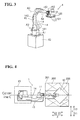
- the depalletizing robot 1 includes a robot main body 11 and a robot hand 12.
- the robot hand 12 is mounted on the distal end of the robot main body 11 in order to suck and hold the workpiece 200 placed on the pallet 201.
- the robot main body 11 includes a base 13 and a robot arm 14.
- the depalletizing robot 1 includes a cable 15 and other elements coupled to the robot arm 14.
- the base 13 is secured to an installation surface such as a floor, a wall, and a ceiling.
- the robot arm 14 has five degrees of freedom.
- the robot arm 14 includes a plurality of arm structures.
- An arm structure 141 is coupled to the base 13 in a rotatable manner about a rotation axis A1, which is perpendicular to the installation surface.
- An arm structure 142 is coupled to the arm structure 141 in a rotatable manner about a rotation axis A2, which is perpendicular to the rotation axis A1.
- An arm structure 143 is coupled to the arm structure 142 in a rotatable manner about a rotation axis A3, which is parallel to the rotation axis A2.
- An arm structure 144 is coupled to the arm structure 143 in a rotatable manner about a rotation axis A4, which is parallel to the rotation axis A3.
- An arm structure 145 is coupled to the arm structure 144 in a rotatable manner about a rotation axis A5, which is perpendicular to the rotation axis A4. It is noted that “parallel” and “perpendicular”, as used herein, are not only intended to mean precisely “parallel” and “perpendicular”, respectively, but also intended more broadly to encompass slight differences from being “parallel” and “perpendicular”.
- Each of the rotation axes A1 to A5 is equipped with a servo motor.
- Each servo motor includes an encoder to detect the rotation position of the servo motor.
- Each servo motor is coupled to the robot controller 3. Thus, each servo motor operates based on a command from the robot controller 3.
- a base portion (which is on an X2 direction side) of the robot hand 12 is coupled to the robot arm 14 (more specifically, to the arm structure 145) such that in plan view, a perpendicular turning axis A5 of the portion (that is, the arm structure 145) of the robot arm 14 to which the base portion of the robot hand 12 is coupled is apart from the geometrical center (the point A, which is the geometrical center of gravity) of the robot hand 12.
- the robot hand 12 has an approximately square shape in plan view, and is coupled to the robot arm 14 at a position adjacent to a corner 12a of the base portion of the approximately square (including orthogonal sides) shape of the robot hand 12.
- the base portion of the robot hand 12 coupled to the robot arm 14 is at a position offset from the geometrical center of the robot hand 12 (that is, from the point A) by a predetermined distance d in the Y direction (more specifically, to a Y2 direction), which is orthogonal to the X direction, in which the robot arm 14 extends.
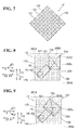
- the robot hand 12 includes a plurality of suction devices 121 and a robot hand main body 122.
- the plurality of suction devices 121 hold the workpiece 200 placed on the pallet 201 by gaseous suction force (or suction force).
- the plurality of suction devices 121 are mounted on the robot hand main body 122.
- the suction devices 121 of the robot hand 12 are each independently coupled to an air sucking tube (not shown). Air is inhaled through the tube and thus the workpiece 200 is sucked (held) onto the suction device 121.
- the suction devices 121 are coupled to the PLC 5 (see FIG. 2 ).
- the PC 6 controls ON and OFF of the air sucking operation of the suction devices 121 (that is, switches between operation mode and nonoperation mode).
- the suction devices 121 are approximately evenly disposed over the surface of the robot hand 12 (robot hand main body 122) in plan view. Specifically, 41 suction devices 121 are disposed over the surface of the robot hand main body 122 in a houndstooth pattern.
- five suction devices 121, four suction devices 121, five suction devices 121, four suction devices 121, five suction devices 121, four suction devices 121, five suction devices 121, four suction devices 121, and five suction devices 121 are arranged along the sides of the approximately square shape of the robot hand main portion 122.
- the PC 6 controls each of the 41 suction devices 121 to independently switch between operation mode and nonoperation mode.
- the suction device 121 is an example of the "holder".
- the PC 6 controls the robot hand 12 to hold the workpiece 200 while controlling the suction devices 121 to switch between operation mode and nonoperation mode independently from each other in accordance with the shape (such as rectangular shape) or the size (such as the area of the workpiece 200 in plan view) of the workpiece 200.
- the PC 6 controls at least one suction device 121 among the suction devices 121 to switch to operation mode, the at least one suction device 121 being disposed in a portion of the robot hand 12 overlapping the workpiece 200, controls the at least one suction device 121 to hold the workpiece 200, and controls the rest of the suction devices 121 to switch to nonoperation mode.
- a suction device 121 When a suction device 121 partially overlaps the workpiece 200, it is possible to switch such suction device 121 into either operation mode or nonoperation mode. It is also possible to switch a suction device 121 to operation mode when equal to or larger than a predetermined area of the suction device 121 overlaps the workpiece 200.
- the PC 6 controls at least one suction device 121 among the suction devices 121 to switch to operation mode, the at least one suction device 121 being disposed in a portion of the robot hand 12 overlapping the workpiece 200, controls the at least one suction device 121 to hold the workpiece 200, and controls the rest of the suction devices 121 to switch to nonoperation mode.
- the workpiece 200 is smaller than the robot hand 12 in plan view as shown in FIG. 8 , those suction devices 121 disposed in the portion of the robot hand 12 overlapping the workpiece 200 switch to operation mode.
- the workpiece 200 is larger than the robot hand 12 in plan view, all the suction devices 121 switch to operation mode.
- the portion of the robot hand 12 where those suction devices 121 to switch to operation mode are disposed is a portion where the robot hand 12 keeps overlapping the workpiece 200 for the period of time from when the workpiece 200 is held until when the workpiece 200 is placed onto the conveyer 202.
- the robot arm 14 moves (rotates) the workpiece 200 in the following manner to hold the workpiece 200.
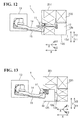
- two orthogonal sides 12b and 12c (outer edges) of the robot hand 12 at the distal end of the robot hand 12 respectively overlap the sides 200a and 200b of the workpiece 200.
- a corner 12d of the robot hand 12 at the distal end of the robot hand 12 overlaps a corner 200c of the workpiece 200.
- the workpiece 200 is held such that the two sides 12b and 12c (outer edges) of the robot hand 12 overlap two of the four sides of the workpiece 200, and such that the corner 12d of the robot hand 12 at the distal end of the robot hand 12 overlaps one of the four corners of the workpiece 200.
- the PC 6 controls the robot hand 12 to hold the workpiece 200 placed on the pallet 201 while controlling the robot arm 14 to turn the suction devices 121 such that the distal ends of the suction devices 121 are oriented in a direction (E1 or E2 direction) crossing the X direction, in which the robot arm 14 extends.
- the robot 2 includes a robot main body 21 and a robot hand 22.
- the robot hand 22 is mounted on the distal end of the robot main body 21.
- the robot main body 21 includes a base 23 and a robot arm 24.
- An arm structure 244 is coupled to the arm structure 243 in a rotatable manner about a rotation axis B4, which is perpendicular to the rotation axis B3.
- An arm structure 245 is coupled to the arm structure 244 in a rotatable manner about a rotation axis B5, which is perpendicular to the rotation axis B4.
- An arm structure 246 is coupled to the arm structure 245 in a rotatable manner about a rotation axis B6, which is perpendicular to the rotation axis B5.
- Each of the rotation axes B1 to B6 is equipped with a servo motor (joint).
- Each servo motor includes an encoder to detect the rotation position of the servo motor.
- Each servo motor is coupled to the robot controller 4.
- each servo motor operates based on a command from the robot controller 4.
- the robot arm 24 is an example of the "second robot arm”.
- the robot hand 22 includes the laser light emitting device 7 and the camera 8 (that is, a stereoscopic camera).
- the laser light emitting device 7 emits laser light to the workpiece 200.
- the camera 8 detects the laser light reflected from the workpiece 200.
- the laser light emitting device 7 is an example of the "detector”.
- the camera 8 is an example of the "detector” and the "image capture device”.
- the laser light emitting device 7 emits, for example, cross-shaped laser light (that is, laser light crossing each other) to the workpiece 200.
- the camera 8 detects (that is, captures an image of) the laser light reflected from the workpiece 200.
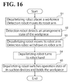
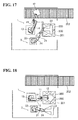
- step S1 based on the latest detection operation by the laser light emitting device 7 and the camera 8 detecting the arrangement state of the workpiece 200 disposed on the uppermost level of the pallet 201, the robot hand 12 of the robot arm 14 holds the workpiece 200, and the robot arm 14 moves to place the workpiece 200 onto the conveyor 202, as shown in FIG. 17 .
- the robot arm 24 moves to arrange the robot hand 22 (the laser light emitting device 7 and the camera 8), which are mounted on the robot arm 24, over the pallet 201.
- the laser light emitting device 7 emits laser light to the workpiece 200
- the camera 8 captures an image of the laser light reflected from the workpiece 200 so as to detect an arrangement state (such as height, shape, and size) of a workpiece 200 next to be held on the pallet 201.
- the next-to-be-held workpiece 200 (which is, for example, disposed on the uppermost level) is selected among a plurality of detected workpieces 200.
- a selection is also made as to which suction devices 121 to switch to operation mode and which suction devices 121 to switch to nonoperation mode at step S5, described later.
- step S3 the robot arm 14 moves to a position over the pallet 201. Then, simultaneously with the movement operation of the robot arm 14, the robot arm 24 is withheld in a direction apart from the pallet 201 from the position adjacent to the pallet 201 in order to avoid collision with the robot arm 14.
- step S4 when the workpiece 200 to be held is disposed on, for example, the Y2 direction side (or on the Y1 direction side), which is orthogonal to the X direction, then as shown in FIGs. 10 and 11 (or FIGs. 12 and 13 ), the robot arm 14 turns the robot hand 12 by approximately 45 degrees to the Y2 direction side (or to the Y1 direction side) from a basic state (see FIG. 4 ). Then, the robot hand 12 moves to a position over the next-to-be-held workpiece 200.
- step S5 the robot hand 12 holds the workpiece 200 such that in plan view, at least one suction device 121 among the suction devices 121 that is disposed in a portion of the robot hand 12 overlapping the workpiece 200 switches to operation mode, while the rest of the suction devices 121 switch to nonoperation mode.
- the processing returns to step S1, where the workpiece 200 is placed onto the conveyor 202. After the workpiece 200 is placed on the conveyor 202, all the suction devices 121 are switched to nonoperation mode.
- the PC 6 controls the robot hand 12 to hold the workpiece 200 while controlling the suction devices 121 to switch between operation mode and nonoperation mode in accordance with the shape or the size of the workpiece 200.
- This enables the suction devices 121 to switch to operation mode in accordance with the shape or the size of the workpiece 200. This, in turn, ensures holding of any workpieces 200 that vary in shape and/or size.
- the PC 6 controls at least one suction device 121 among the suction devices 121 to switch to operation mode, the at least one suction device 121 being disposed in a portion of the robot hand 12 overlapping the workpiece 200 in plan view, controls the at least one suction device 121 to hold the workpiece 200, and controls the rest of the suction devices 121 to switch to nonoperation mode.
- the suction devices 121 readily match the shape or the size of the workpiece 200 by switching the suction devices 121 to operation mode. This facilitates holding of any workpieces 200 that vary in shape and/or size.
- the robot system 100 When the robot system 100 has a limited amount of air suction, it is possible to control those suction devices 121 disposed in portions of the robot hand 12 other than the portion overlapping the workpiece 200 to switch to nonoperation mode. This increases the amount of air suction on the suction devices 121 in operation mode and enhances the suction force of the suction devices 121 in operation mode.
- the laser light emitting device 7 and the camera 8 detect the shape or the size of the workpiece 200 placed on the pallet 201.
- the PC 6 controls the robot hand 12 to hold the workpiece 200 while controlling the suction devices 121 to switch between operation mode and nonoperation mode in accordance with the shape or the size of the workpiece 200 detected by the laser light emitting device 7 and the camera 8.
- the laser light emitting device 7 and the camera 8 detect the shape or the size of the workpiece 200, and in accordance with the shape or the size of the workpiece 200, the suction devices 121 are readily switched between operation mode and nonoperation mode.
- the PC 6 controls each of the suction devices 121 to independently switch between operation mode and nonoperation mode.
- the suction devices 121 readily switch to operation mode or nonoperation mode in accordance with the shape or the size of the workpiece 200.
- the above-described embodiment has been illustrated as using two robots, namely, the depalletizing robot having five degrees of freedom and the detection robot having six degrees of freedom to detect an arrangement state of the workpiece disposed on the pallet and to hold and transfer the workpiece. It is also possible to use a single two-arm robot to detect an arrangement state of the workpiece disposed on the pallet and to hold and transfer the workpiece.
- the number of control axes for each of the depalletizing robot and the detection robot is selectable conveniently. For example, it is possible to use a robot arm having four degrees of freedom or a robot arm having more than four degrees of freedom for each of the depalletizing robot and the detection robot.
- suction force is used to hold the workpiece. It is also possible to use electromagnetic force (that is, magnetic force using a magnet) to hold the workpiece.
- suction devices are provided on the robot hand.
- the robot hand may include any other number of the suction devices than 41.
- the workpiece is held such that at least one suction device among the suction devices that is disposed in a portion of the robot hand overlapping the workpiece in plan view switches to operation mode, and the rest of the suction devices switch to nonoperation mode.
- at least one suction device among the suction devices that is disposed in a portion of the robot hand overlapping the workpiece in plan view switches to operation mode, and the rest of the suction devices switch to nonoperation mode.
- some of the suction devices disposed in the portion of the robot hand overlapping the workpiece switch to nonoperation mode.
- the portion of the robot hand where the suction devices to switch to operation mode are disposed is a portion where the robot hand keeps overlapping the workpiece for the period of time from when the workpiece is held until when the workpiece is placed onto the conveyer.
- Another possible example is that at the start of holding of the workpiece, some of the suction devices (suction devices disposed in the vicinity of the outer edge of the workpiece) disposed in the portion of the robot hand overlapping the workpiece switch to nonoperation mode, and then all the suction devices disposed in the portion of the robot hand overlapping the workpiece switch operation mode. This eliminates or minimizes erroneous holding of a workpiece adjacent to the workpiece actually to be held.
- the suction devices switch between operation mode and nonoperation mode in accordance with the shape or the size of the workpiece detected by the laser light emitting device and the camera.
- Another possible example is that when the shape or the size of the workpiece is known in advance, it is not necessary to provide the laser light emitting device and the camera; the suction devices may switch between operation mode and nonoperation mode based on the known shape or size of the workpiece.
- each of the suction devices is independently switchable between operation mode and nonoperation mode.
- Another possible example is to switch a unit of a predetermined number of suction devices (for example, each set of four suction devices) between operation mode and nonoperation mode. This facilitates the switching control of the plurality of suction devices.
- the suction devices are arranged in a houndstooth pattern over the surface of the robot hand.
- Another possible example is to arrange the suction devices in a matrix.
- the workpiece is held at the distal end of the robot hand.
- Another possible example is to hold the workpiece at the center of the robot hand.
- the robot hand has been illustrated as having an approximately square shape in plan view.
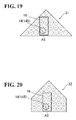
- a robot hand 31 according to a first modification shown in FIG. 19 .
- the robot hand 31 has an approximately triangular shape having two sides orthogonal to each other at the distal end portion of the robot hand 31.
- a robot hand 32 according to a second modification shown in FIG. 20 .
- the robot hand 32 has an approximately hexagonal shape having two sides orthogonal to each other at the distal end portion of the robot hand 32.
- the robot hand may also have a shape other than a polygonal shape such as an approximately square shape (examples including, but not limited to, an elliptical shape).
- at least one suction device among the suction devices that is disposed in the portion of the robot hand overlapping the workpiece switch to operation mode, and the rest of the suction devices switch to nonoperation mode.
- a depalletizing operation has been illustrated, in which the workpieces stacked on the pallet are depalletized by the robot system.
- the robot system may also perform an operation other than the depalletizing operation, examples including, but not limited to, a palletizing operation.
- the PC has been illustrated as controlling the operation of the robot (the robot system). It is also possible to use a PLC or a robot controller to control the operation of the robot.
Landscapes
- Engineering & Computer Science (AREA)
- Robotics (AREA)
- Mechanical Engineering (AREA)
- Health & Medical Sciences (AREA)
- General Health & Medical Sciences (AREA)
- Orthopedic Medicine & Surgery (AREA)
- Manipulator (AREA)
Applications Claiming Priority (1)
| Application Number | Priority Date | Filing Date | Title |
|---|---|---|---|
| JP2013052167A JP2014176926A (ja) | 2013-03-14 | 2013-03-14 | ロボットシステムおよびワークの搬送方法 |
Publications (2)
| Publication Number | Publication Date |
|---|---|
| EP2783801A2 true EP2783801A2 (de) | 2014-10-01 |
| EP2783801A3 EP2783801A3 (de) | 2015-03-04 |
Family
ID=50189584
Family Applications (1)
| Application Number | Title | Priority Date | Filing Date |
|---|---|---|---|
| EP14157417.8A Withdrawn EP2783801A3 (de) | 2013-03-14 | 2014-03-03 | Robotersystem und Verfahren zur Übertragung eines Werkstückes |
Country Status (4)
| Country | Link |
|---|---|
| US (1) | US20140277721A1 (de) |
| EP (1) | EP2783801A3 (de) |
| JP (1) | JP2014176926A (de) |
| CN (1) | CN104044151A (de) |
Cited By (2)
| Publication number | Priority date | Publication date | Assignee | Title |
|---|---|---|---|---|
| US10315865B2 (en) * | 2015-11-12 | 2019-06-11 | Kabushiki Kaisha Toshiba | Conveying device, conveying system, and conveying method |
| WO2021045944A1 (en) * | 2019-09-04 | 2021-03-11 | The Steelastic Company, Llc | Transfer tooling for varying tire belt sizes |
Families Citing this family (32)
| Publication number | Priority date | Publication date | Assignee | Title |
|---|---|---|---|---|
| US9205558B1 (en) * | 2014-07-16 | 2015-12-08 | Google Inc. | Multiple suction cup control |
| JP6486114B2 (ja) * | 2015-01-16 | 2019-03-20 | 株式会社東芝 | 荷役装置 |
| JP6034892B2 (ja) * | 2015-01-27 | 2016-11-30 | ファナック株式会社 | ロボットの設置台の輝度が変化するロボットシステム |
| CN104723325B (zh) * | 2015-03-17 | 2016-04-20 | 南京理工大学 | 一种用于自动化生产线的送料机械手 |
| CN104760826B (zh) * | 2015-04-13 | 2017-12-19 | 上海金东唐科技有限公司 | 自动微调测试设备 |
| NL2014635B1 (en) | 2015-04-14 | 2017-01-20 | Vmi Holland Bv | Gripper, gripper assembly and method for gripping a tire component. |
| CN105522565A (zh) * | 2016-01-26 | 2016-04-27 | 中塑联新材料科技湖北有限公司 | 一种塑料板或塑料片材码垛机械手 |
| US10221015B2 (en) * | 2016-06-27 | 2019-03-05 | Amazon Technologies, Inc. | Automated item singulation |
| JP2018122945A (ja) * | 2017-01-30 | 2018-08-09 | 株式会社東芝 | 可変型物品保持装置、移載装置、ロボットハンドリングシステム、および移載装置の制御方法 |
| NL2018380B1 (en) * | 2017-02-15 | 2018-09-06 | Vmi Holland Bv | Transfer device and method for transferring a tire component |
| CN106829462A (zh) * | 2017-03-07 | 2017-06-13 | 河南摩西机械制造有限公司 | 一种铁锅搬运机械手 |
| JP2018203480A (ja) * | 2017-06-07 | 2018-12-27 | 株式会社東芝 | 仕分装置および仕分システム |
| CN107253227A (zh) * | 2017-07-25 | 2017-10-17 | 广州锦湖自动化设备有限公司 | 自动剪镜片机 |
| JP7109904B2 (ja) | 2017-11-02 | 2022-08-01 | 株式会社東芝 | 取り出しシステム |
| JP6917920B2 (ja) | 2018-02-19 | 2021-08-11 | 株式会社東芝 | 搬送システム、及び搬送方法 |
| JP7000213B2 (ja) * | 2018-03-19 | 2022-01-19 | 株式会社東芝 | 保持装置、搬送システム、コントローラ、および保持方法 |
| JP6937260B2 (ja) * | 2018-03-19 | 2021-09-22 | 株式会社東芝 | 把持制御装置、把持システム、およびプログラム |
| DE102018208126A1 (de) * | 2018-05-23 | 2019-11-28 | Trumpf Werkzeugmaschinen Gmbh + Co. Kg | Verfahren zum Hantieren eines Werkstücks mit Hilfe eines Entnahmewerkzeugs und Maschine zur Durchführung des Verfahrens |
| JP7141288B2 (ja) * | 2018-09-25 | 2022-09-22 | 川崎重工業株式会社 | ロボットシステム |
| US10335947B1 (en) * | 2019-01-18 | 2019-07-02 | Mujin, Inc. | Robotic system with piece-loss management mechanism |
| JP7211208B2 (ja) * | 2019-03-28 | 2023-01-24 | 株式会社Ihi | デパレタイズ装置及びデパレタイズ方法 |
| JP6958593B2 (ja) * | 2019-05-29 | 2021-11-02 | 村田機械株式会社 | 移載装置 |
| CN112405570A (zh) | 2019-08-21 | 2021-02-26 | 牧今科技 | 用于夹持和保持物体的机器人多夹持器组件和方法 |
| CN111993448B (zh) * | 2019-08-21 | 2022-02-08 | 牧今科技 | 用于夹持和保持物体的机器人多夹持器组件和方法 |
| US11345029B2 (en) | 2019-08-21 | 2022-05-31 | Mujin, Inc. | Robotic multi-gripper assemblies and methods for gripping and holding objects |
| JP7123885B2 (ja) * | 2019-09-13 | 2022-08-23 | 株式会社東芝 | ハンドリング装置、制御装置、および保持方法 |
| TWI702179B (zh) * | 2019-12-05 | 2020-08-21 | 所羅門股份有限公司 | 取物系統及方法 |
| JP7467951B2 (ja) | 2020-02-03 | 2024-04-16 | 株式会社デンソーウェーブ | ワークの吸着装置 |
| KR102169074B1 (ko) * | 2020-03-19 | 2020-10-22 | 주식회사 에이스로보테크 | 전자석을 이용하는 커넥팅 로드 이송용 로봇 |
| JP7457546B2 (ja) | 2020-03-23 | 2024-03-28 | 株式会社日立オートメーション | ロボットハンド |
| JP7341431B2 (ja) | 2020-08-05 | 2023-09-11 | リョーエイ株式会社 | 段積みされた箱のハンドリング方法及び装置 |
| CN114311007A (zh) * | 2022-01-14 | 2022-04-12 | 上海交通大学 | 一种抓取钢板的柔性电磁铁抓手 |
Citations (1)
| Publication number | Priority date | Publication date | Assignee | Title |
|---|---|---|---|---|
| JP2001317911A (ja) | 2000-05-02 | 2001-11-16 | Daifuku Co Ltd | 物品位置認識装置 |
Family Cites Families (13)
| Publication number | Priority date | Publication date | Assignee | Title |
|---|---|---|---|---|
| JPS59152089A (ja) * | 1983-02-16 | 1984-08-30 | 株式会社ブリヂストン | 工業用ロボツトのハンド |
| JPS61214989A (ja) * | 1985-03-15 | 1986-09-24 | 三菱電機株式会社 | 産業用ロボツトのハンド装置 |
| JPH0727135Y2 (ja) * | 1990-05-18 | 1995-06-21 | 株式会社名機製作所 | 成形機用取出機 |
| JP2530420Y2 (ja) * | 1990-10-31 | 1997-03-26 | 株式会社テクノクリート | 脱型装置 |
| JP3448413B2 (ja) * | 1995-12-11 | 2003-09-22 | 株式会社リコー | 水平多関節型ロボットの座標補正装置 |
| JPH09285986A (ja) * | 1996-04-23 | 1997-11-04 | Ricoh Co Ltd | エンドエフェクタ |
| JPH10120354A (ja) * | 1996-10-21 | 1998-05-12 | Amada Co Ltd | 板金ワーク用バキュームパッドの選択作動システム |
| JP2000127074A (ja) * | 1998-10-23 | 2000-05-09 | Tsubakimoto Chain Co | 把持装置 |
| KR100456858B1 (ko) * | 2002-12-18 | 2004-11-10 | 현대자동차주식회사 | 어태치먼트의 수직축 다단 조절장치 |
| JP4112570B2 (ja) * | 2004-05-21 | 2008-07-02 | ファナック株式会社 | 産業用ロボットの線条体処理構造 |
| JP5190838B2 (ja) * | 2007-09-28 | 2013-04-24 | 株式会社ユーシン精機 | 把持具 |
| JP2010005769A (ja) * | 2008-06-30 | 2010-01-14 | Ihi Corp | デパレタイズ装置および方法 |
| CN102050564A (zh) * | 2009-10-30 | 2011-05-11 | 孙月卫 | 切割液晶显示器单元母板的方法及其自动化切割系统 |
-
2013
- 2013-03-14 JP JP2013052167A patent/JP2014176926A/ja active Pending
-
2014
- 2014-01-07 CN CN201410006635.2A patent/CN104044151A/zh active Pending
- 2014-03-03 EP EP14157417.8A patent/EP2783801A3/de not_active Withdrawn
- 2014-03-14 US US14/210,446 patent/US20140277721A1/en not_active Abandoned
Patent Citations (1)
| Publication number | Priority date | Publication date | Assignee | Title |
|---|---|---|---|---|
| JP2001317911A (ja) | 2000-05-02 | 2001-11-16 | Daifuku Co Ltd | 物品位置認識装置 |
Cited By (3)
| Publication number | Priority date | Publication date | Assignee | Title |
|---|---|---|---|---|
| US10315865B2 (en) * | 2015-11-12 | 2019-06-11 | Kabushiki Kaisha Toshiba | Conveying device, conveying system, and conveying method |
| WO2021045944A1 (en) * | 2019-09-04 | 2021-03-11 | The Steelastic Company, Llc | Transfer tooling for varying tire belt sizes |
| CN114364522A (zh) * | 2019-09-04 | 2022-04-15 | 斯第莱斯梯克有限公司 | 用于不同的轮胎皮带尺寸的传送工具 |
Also Published As
| Publication number | Publication date |
|---|---|
| JP2014176926A (ja) | 2014-09-25 |
| CN104044151A (zh) | 2014-09-17 |
| US20140277721A1 (en) | 2014-09-18 |
| EP2783801A3 (de) | 2015-03-04 |
Similar Documents
| Publication | Publication Date | Title |
|---|---|---|
| EP2783801A2 (de) | Robotersystem und Verfahren zur Übertragung eines Werkstückes | |
| US9352463B2 (en) | Robot system and method for transferring workpiece | |
| EP2711144A1 (de) | Robotersystem und Werkstückübertragungsverfahren | |
| JP6942576B2 (ja) | 搬送装置 | |
| JP7117193B2 (ja) | ロボット及びそれを備えるロボットシステム | |
| JP5304469B2 (ja) | ビンピッキングシステム | |
| JP7117192B2 (ja) | ロボットハンド、ロボット及びロボットシステム | |
| EP2845699A2 (de) | Roboterhand, Robotersystem und Verfahren zum Depalettieren eines Artikels | |
| US20130085604A1 (en) | Robot apparatus, robot system, and method for producing a to-be-processed material | |
| KR101952767B1 (ko) | 로봇 | |
| JP7186546B2 (ja) | 移載装置 | |
| JP5522298B2 (ja) | ビンピッキングシステム | |
| JP5535884B2 (ja) | ワーク取り出し方法 | |
| JP2019042828A (ja) | ピッキング設備 | |
| CN117355392A (zh) | 集成移动机械手机器人 | |
| JP2019151421A (ja) | 物品移載装置及び荷取位置検出装置 | |
| JP2023115274A (ja) | 取出装置 | |
| JP2020044588A (ja) | 物品移動装置およびロボットアームのエンドエフェクタ | |
| WO2020100908A1 (ja) | 物品積載設備(article loading facility) | |
| WO2020105295A1 (ja) | 画像情報処理装置、把持システム、および画像情報処理方法 | |
| JP2014061561A (ja) | ロボットシステムおよび物品製造方法 | |
| CN115485217A (zh) | 设定堆叠工件的位置的位置设定装置和具备位置设定装置的机器人装置 | |
| WO2023127373A1 (ja) | ロボットシステム | |
| JP7192682B2 (ja) | 検査システム | |
| WO2023101027A1 (ja) | 基板搬送ロボットの制御装置及び関節モータの制御方法 |
Legal Events
| Date | Code | Title | Description |
|---|---|---|---|
| 17P | Request for examination filed |
Effective date: 20140303 |
|
| AK | Designated contracting states |
Kind code of ref document: A2 Designated state(s): AL AT BE BG CH CY CZ DE DK EE ES FI FR GB GR HR HU IE IS IT LI LT LU LV MC MK MT NL NO PL PT RO RS SE SI SK SM TR |
|
| AX | Request for extension of the european patent |
Extension state: BA ME |
|
| PUAI | Public reference made under article 153(3) epc to a published international application that has entered the european phase |
Free format text: ORIGINAL CODE: 0009012 |
|
| PUAL | Search report despatched |
Free format text: ORIGINAL CODE: 0009013 |
|
| AK | Designated contracting states |
Kind code of ref document: A3 Designated state(s): AL AT BE BG CH CY CZ DE DK EE ES FI FR GB GR HR HU IE IS IT LI LT LU LV MC MK MT NL NO PL PT RO RS SE SI SK SM TR |
|
| AX | Request for extension of the european patent |
Extension state: BA ME |
|
| RIC1 | Information provided on ipc code assigned before grant |
Ipc: B25J 9/16 20060101AFI20150129BHEP |
|
| STAA | Information on the status of an ep patent application or granted ep patent |
Free format text: STATUS: THE APPLICATION IS DEEMED TO BE WITHDRAWN |
|
| 18D | Application deemed to be withdrawn |
Effective date: 20150905 |