EP2783801A2 - Robot system and method for transferring workpiece - Google Patents
Robot system and method for transferring workpiece Download PDFInfo
- Publication number
- EP2783801A2 EP2783801A2 EP14157417.8A EP14157417A EP2783801A2 EP 2783801 A2 EP2783801 A2 EP 2783801A2 EP 14157417 A EP14157417 A EP 14157417A EP 2783801 A2 EP2783801 A2 EP 2783801A2
- Authority
- EP
- European Patent Office
- Prior art keywords
- workpiece
- robot
- robot hand
- holders
- switch
- Prior art date
- Legal status (The legal status is an assumption and is not a legal conclusion. Google has not performed a legal analysis and makes no representation as to the accuracy of the status listed.)
- Withdrawn
Links
- 238000000034 method Methods 0.000 title claims description 6
- 238000001514 detection method Methods 0.000 description 12
- 238000010586 diagram Methods 0.000 description 9
- 238000012986 modification Methods 0.000 description 6
- 230000004048 modification Effects 0.000 description 6
- 238000009434 installation Methods 0.000 description 4
- 230000005484 gravity Effects 0.000 description 1
- 239000011159 matrix material Substances 0.000 description 1
Images


Classifications
-
- B—PERFORMING OPERATIONS; TRANSPORTING
- B25—HAND TOOLS; PORTABLE POWER-DRIVEN TOOLS; MANIPULATORS
- B25J—MANIPULATORS; CHAMBERS PROVIDED WITH MANIPULATION DEVICES
- B25J9/00—Programme-controlled manipulators
- B25J9/16—Programme controls
- B25J9/1612—Programme controls characterised by the hand, wrist, grip control
-
- B—PERFORMING OPERATIONS; TRANSPORTING
- B25—HAND TOOLS; PORTABLE POWER-DRIVEN TOOLS; MANIPULATORS
- B25J—MANIPULATORS; CHAMBERS PROVIDED WITH MANIPULATION DEVICES
- B25J15/00—Gripping heads and other end effectors
- B25J15/06—Gripping heads and other end effectors with vacuum or magnetic holding means
-
- G—PHYSICS
- G05—CONTROLLING; REGULATING
- G05B—CONTROL OR REGULATING SYSTEMS IN GENERAL; FUNCTIONAL ELEMENTS OF SUCH SYSTEMS; MONITORING OR TESTING ARRANGEMENTS FOR SUCH SYSTEMS OR ELEMENTS
- G05B2219/00—Program-control systems
- G05B2219/30—Nc systems
- G05B2219/39—Robotics, robotics to robotics hand
- G05B2219/39558—Vacuum hand has selective gripper area
-
- G—PHYSICS
- G05—CONTROLLING; REGULATING
- G05B—CONTROL OR REGULATING SYSTEMS IN GENERAL; FUNCTIONAL ELEMENTS OF SUCH SYSTEMS; MONITORING OR TESTING ARRANGEMENTS FOR SUCH SYSTEMS OR ELEMENTS
- G05B2219/00—Program-control systems
- G05B2219/30—Nc systems
- G05B2219/40—Robotics, robotics mapping to robotics vision
- G05B2219/40006—Placing, palletize, un palletize, paper roll placing, box stacking
-
- Y—GENERAL TAGGING OF NEW TECHNOLOGICAL DEVELOPMENTS; GENERAL TAGGING OF CROSS-SECTIONAL TECHNOLOGIES SPANNING OVER SEVERAL SECTIONS OF THE IPC; TECHNICAL SUBJECTS COVERED BY FORMER USPC CROSS-REFERENCE ART COLLECTIONS [XRACs] AND DIGESTS
- Y10—TECHNICAL SUBJECTS COVERED BY FORMER USPC
- Y10S—TECHNICAL SUBJECTS COVERED BY FORMER USPC CROSS-REFERENCE ART COLLECTIONS [XRACs] AND DIGESTS
- Y10S901/00—Robots
- Y10S901/30—End effector
- Y10S901/40—Vacuum or mangetic
Definitions
- Japanese Unexamined Patent Application Publication No. 2001-317911 discloses a depalletizing apparatus that includes a robot arm.
- the robot arm includes a hand to hold a workpiece placed on a pallet.
- the depalletizing apparatus captures an image of the workpiece from above the pallet and detects the position of the workpiece based on the captured image.
- the robot arm is moved based on the detected position of the workpiece, and the hand holds the workpiece.
- the hand (specifically, a workpiece holding portion of the hand) is not able to hold a workpiece when the shape and size of the hand largely differ from the shape and size of the workpiece.
- the hand may not be able to hold a workpiece when the workpiece varies in shape and/or size. This is especially true when the hand is of the type that utilizes electromagnetic force or suction force to hold a workpiece.
- the present invention has been made in view of the above-described circumstances, and it is one object of the present invention to provide a robot system and a method for transferring a workpiece that ensure holding of any workpieces that vary in shape and/or size.
- a robot system 100 includes a robot hand 12, 31, 32 and a controller 6.
- the robot hand 12, 31, 32 includes a plurality of holders 121 configured to hold a workpiece placed on a workpiece placement stand 201 using at least one of electromagnetic force and suction force.
- the controller 6 is configured to control the plurality of holders 121 to hold the workpiece while controlling the plurality of holders 121 to switch between operation mode and nonoperation mode in accordance with at least one of a shape and a size of the workpiece.
- the controller controls a plurality of holders to hold a workpiece while controlling the plurality of holders to switch between operation mode and nonoperation mode in accordance with the shape or size of the workpiece. This ensures that the plurality of holders switch to operation mode in accordance with the shape or size of the workpiece. This, in turn, ensures holding of the workpiece even when the workpiece varies in shape and/or size.
- a method for transferring a workpiece includes switching a plurality of holders 121 between operation mode and nonoperation mode in accordance with at least one of a shape and a size of the workpiece.
- the plurality of holders 121 are mounted on a robot hand 12, 31, 32 and configured to hold the workpiece placed on a workpiece placement stand 201 using at least one of electromagnetic force and suction force.
- the workpiece is held while the plurality of holders 121 are controlled to switch between operation mode and nonoperation mode.
- a plurality of holders mounted on a robot hand are switched between operation mode and nonoperation mode in accordance with the shape or size of the workpiece. This ensures that the plurality of holders switch to operation mode in accordance with the shape or size of the workpiece. This, in turn, ensures holding of the workpiece even when the workpiece varies in shape and/or size.
- FIGs. 1 to 15 a configuration of a robot system 100 according to an embodiment will be described by referring to FIGs. 1 to 15 .
- the robot system 100 includes a depalletizing robot 1 and a detection robot 2.
- the detection robot 2 detects a workpiece 200.
- Examples of the depalletizing robot 1 and the detection robot 2 include, but are not limited to, a perpendicularly articulated robot.
- a pallet 201 is disposed adjacent to (on an X1 direction side of) the depalletizing robot 1 and the detection robot 2.
- On the pallet 201 a plurality of workpieces 200 of different sizes and shapes are stacked.
- Examples of the workpiece 200 include, but are not limited to, a box-shaped workpiece.
- the pallet 201 has an approximately rectangular shaped portion (that is, a box-shape having walls).
- the approximately rectangular shaped portion of the pallet 201 surrounds the workpieces 200.
- a conveyor 202 is disposed adjacent to (on a Y2 direction side of) the depalletizing robot 1.
- the conveyor 202 receives (and transfers) the workpiece 200.
- the pallet 201 is an example of the "workpiece placement stand”.
- the depalletizing robot 1 is coupled to a robot controller 3.
- the detection robot 2 is coupled to a robot controller 4.
- the robot controller 3 and the robot controller 4 are coupled to a PLC (programmable logic controller) 5.
- the PLC 5 is coupled to a PC (Personal Computer) 6.
- the PC 6 controls an overall operation of the robot system 100.
- the PC 6 is also coupled to a laser light emitting device 7 and a camera 8.
- the laser light emitting device 7 and the camera 8 detect the arrangement state of the workpiece 200.
- the PC 6 is an example of the "controller”.
- the depalletizing robot 1 includes a robot main body 11 and a robot hand 12.
- the robot hand 12 is mounted on the distal end of the robot main body 11 in order to suck and hold the workpiece 200 placed on the pallet 201.
- the robot main body 11 includes a base 13 and a robot arm 14.
- the depalletizing robot 1 includes a cable 15 and other elements coupled to the robot arm 14.
- the base 13 is secured to an installation surface such as a floor, a wall, and a ceiling.
- the robot arm 14 has five degrees of freedom.
- the robot arm 14 includes a plurality of arm structures.
- An arm structure 141 is coupled to the base 13 in a rotatable manner about a rotation axis A1, which is perpendicular to the installation surface.
- An arm structure 142 is coupled to the arm structure 141 in a rotatable manner about a rotation axis A2, which is perpendicular to the rotation axis A1.
- An arm structure 143 is coupled to the arm structure 142 in a rotatable manner about a rotation axis A3, which is parallel to the rotation axis A2.
- An arm structure 144 is coupled to the arm structure 143 in a rotatable manner about a rotation axis A4, which is parallel to the rotation axis A3.
- An arm structure 145 is coupled to the arm structure 144 in a rotatable manner about a rotation axis A5, which is perpendicular to the rotation axis A4. It is noted that “parallel” and “perpendicular”, as used herein, are not only intended to mean precisely “parallel” and “perpendicular”, respectively, but also intended more broadly to encompass slight differences from being “parallel” and “perpendicular”.
- Each of the rotation axes A1 to A5 is equipped with a servo motor.
- Each servo motor includes an encoder to detect the rotation position of the servo motor.
- Each servo motor is coupled to the robot controller 3. Thus, each servo motor operates based on a command from the robot controller 3.
- a base portion (which is on an X2 direction side) of the robot hand 12 is coupled to the robot arm 14 (more specifically, to the arm structure 145) such that in plan view, a perpendicular turning axis A5 of the portion (that is, the arm structure 145) of the robot arm 14 to which the base portion of the robot hand 12 is coupled is apart from the geometrical center (the point A, which is the geometrical center of gravity) of the robot hand 12.
- the robot hand 12 has an approximately square shape in plan view, and is coupled to the robot arm 14 at a position adjacent to a corner 12a of the base portion of the approximately square (including orthogonal sides) shape of the robot hand 12.
- the base portion of the robot hand 12 coupled to the robot arm 14 is at a position offset from the geometrical center of the robot hand 12 (that is, from the point A) by a predetermined distance d in the Y direction (more specifically, to a Y2 direction), which is orthogonal to the X direction, in which the robot arm 14 extends.
- the robot hand 12 includes a plurality of suction devices 121 and a robot hand main body 122.
- the plurality of suction devices 121 hold the workpiece 200 placed on the pallet 201 by gaseous suction force (or suction force).
- the plurality of suction devices 121 are mounted on the robot hand main body 122.
- the suction devices 121 of the robot hand 12 are each independently coupled to an air sucking tube (not shown). Air is inhaled through the tube and thus the workpiece 200 is sucked (held) onto the suction device 121.
- the suction devices 121 are coupled to the PLC 5 (see FIG. 2 ).
- the PC 6 controls ON and OFF of the air sucking operation of the suction devices 121 (that is, switches between operation mode and nonoperation mode).
- the suction devices 121 are approximately evenly disposed over the surface of the robot hand 12 (robot hand main body 122) in plan view. Specifically, 41 suction devices 121 are disposed over the surface of the robot hand main body 122 in a houndstooth pattern.
- five suction devices 121, four suction devices 121, five suction devices 121, four suction devices 121, five suction devices 121, four suction devices 121, five suction devices 121, four suction devices 121, and five suction devices 121 are arranged along the sides of the approximately square shape of the robot hand main portion 122.
- the PC 6 controls each of the 41 suction devices 121 to independently switch between operation mode and nonoperation mode.
- the suction device 121 is an example of the "holder".
- the PC 6 controls the robot hand 12 to hold the workpiece 200 while controlling the suction devices 121 to switch between operation mode and nonoperation mode independently from each other in accordance with the shape (such as rectangular shape) or the size (such as the area of the workpiece 200 in plan view) of the workpiece 200.
- the PC 6 controls at least one suction device 121 among the suction devices 121 to switch to operation mode, the at least one suction device 121 being disposed in a portion of the robot hand 12 overlapping the workpiece 200, controls the at least one suction device 121 to hold the workpiece 200, and controls the rest of the suction devices 121 to switch to nonoperation mode.
- a suction device 121 When a suction device 121 partially overlaps the workpiece 200, it is possible to switch such suction device 121 into either operation mode or nonoperation mode. It is also possible to switch a suction device 121 to operation mode when equal to or larger than a predetermined area of the suction device 121 overlaps the workpiece 200.
- the PC 6 controls at least one suction device 121 among the suction devices 121 to switch to operation mode, the at least one suction device 121 being disposed in a portion of the robot hand 12 overlapping the workpiece 200, controls the at least one suction device 121 to hold the workpiece 200, and controls the rest of the suction devices 121 to switch to nonoperation mode.
- the workpiece 200 is smaller than the robot hand 12 in plan view as shown in FIG. 8 , those suction devices 121 disposed in the portion of the robot hand 12 overlapping the workpiece 200 switch to operation mode.
- the workpiece 200 is larger than the robot hand 12 in plan view, all the suction devices 121 switch to operation mode.
- the portion of the robot hand 12 where those suction devices 121 to switch to operation mode are disposed is a portion where the robot hand 12 keeps overlapping the workpiece 200 for the period of time from when the workpiece 200 is held until when the workpiece 200 is placed onto the conveyer 202.
- the robot arm 14 moves (rotates) the workpiece 200 in the following manner to hold the workpiece 200.
- two orthogonal sides 12b and 12c (outer edges) of the robot hand 12 at the distal end of the robot hand 12 respectively overlap the sides 200a and 200b of the workpiece 200.
- a corner 12d of the robot hand 12 at the distal end of the robot hand 12 overlaps a corner 200c of the workpiece 200.
- the workpiece 200 is held such that the two sides 12b and 12c (outer edges) of the robot hand 12 overlap two of the four sides of the workpiece 200, and such that the corner 12d of the robot hand 12 at the distal end of the robot hand 12 overlaps one of the four corners of the workpiece 200.
- the PC 6 controls the robot hand 12 to hold the workpiece 200 placed on the pallet 201 while controlling the robot arm 14 to turn the suction devices 121 such that the distal ends of the suction devices 121 are oriented in a direction (E1 or E2 direction) crossing the X direction, in which the robot arm 14 extends.
- the robot 2 includes a robot main body 21 and a robot hand 22.
- the robot hand 22 is mounted on the distal end of the robot main body 21.
- the robot main body 21 includes a base 23 and a robot arm 24.
- An arm structure 244 is coupled to the arm structure 243 in a rotatable manner about a rotation axis B4, which is perpendicular to the rotation axis B3.
- An arm structure 245 is coupled to the arm structure 244 in a rotatable manner about a rotation axis B5, which is perpendicular to the rotation axis B4.
- An arm structure 246 is coupled to the arm structure 245 in a rotatable manner about a rotation axis B6, which is perpendicular to the rotation axis B5.
- Each of the rotation axes B1 to B6 is equipped with a servo motor (joint).
- Each servo motor includes an encoder to detect the rotation position of the servo motor.
- Each servo motor is coupled to the robot controller 4.
- each servo motor operates based on a command from the robot controller 4.
- the robot arm 24 is an example of the "second robot arm”.
- the robot hand 22 includes the laser light emitting device 7 and the camera 8 (that is, a stereoscopic camera).
- the laser light emitting device 7 emits laser light to the workpiece 200.
- the camera 8 detects the laser light reflected from the workpiece 200.
- the laser light emitting device 7 is an example of the "detector”.
- the camera 8 is an example of the "detector” and the "image capture device”.
- the laser light emitting device 7 emits, for example, cross-shaped laser light (that is, laser light crossing each other) to the workpiece 200.
- the camera 8 detects (that is, captures an image of) the laser light reflected from the workpiece 200.
- step S1 based on the latest detection operation by the laser light emitting device 7 and the camera 8 detecting the arrangement state of the workpiece 200 disposed on the uppermost level of the pallet 201, the robot hand 12 of the robot arm 14 holds the workpiece 200, and the robot arm 14 moves to place the workpiece 200 onto the conveyor 202, as shown in FIG. 17 .
- the robot arm 24 moves to arrange the robot hand 22 (the laser light emitting device 7 and the camera 8), which are mounted on the robot arm 24, over the pallet 201.
- the laser light emitting device 7 emits laser light to the workpiece 200
- the camera 8 captures an image of the laser light reflected from the workpiece 200 so as to detect an arrangement state (such as height, shape, and size) of a workpiece 200 next to be held on the pallet 201.
- the next-to-be-held workpiece 200 (which is, for example, disposed on the uppermost level) is selected among a plurality of detected workpieces 200.
- a selection is also made as to which suction devices 121 to switch to operation mode and which suction devices 121 to switch to nonoperation mode at step S5, described later.
- step S3 the robot arm 14 moves to a position over the pallet 201. Then, simultaneously with the movement operation of the robot arm 14, the robot arm 24 is withheld in a direction apart from the pallet 201 from the position adjacent to the pallet 201 in order to avoid collision with the robot arm 14.
- step S4 when the workpiece 200 to be held is disposed on, for example, the Y2 direction side (or on the Y1 direction side), which is orthogonal to the X direction, then as shown in FIGs. 10 and 11 (or FIGs. 12 and 13 ), the robot arm 14 turns the robot hand 12 by approximately 45 degrees to the Y2 direction side (or to the Y1 direction side) from a basic state (see FIG. 4 ). Then, the robot hand 12 moves to a position over the next-to-be-held workpiece 200.
- step S5 the robot hand 12 holds the workpiece 200 such that in plan view, at least one suction device 121 among the suction devices 121 that is disposed in a portion of the robot hand 12 overlapping the workpiece 200 switches to operation mode, while the rest of the suction devices 121 switch to nonoperation mode.
- the processing returns to step S1, where the workpiece 200 is placed onto the conveyor 202. After the workpiece 200 is placed on the conveyor 202, all the suction devices 121 are switched to nonoperation mode.
- the PC 6 controls the robot hand 12 to hold the workpiece 200 while controlling the suction devices 121 to switch between operation mode and nonoperation mode in accordance with the shape or the size of the workpiece 200.
- This enables the suction devices 121 to switch to operation mode in accordance with the shape or the size of the workpiece 200. This, in turn, ensures holding of any workpieces 200 that vary in shape and/or size.
- the PC 6 controls at least one suction device 121 among the suction devices 121 to switch to operation mode, the at least one suction device 121 being disposed in a portion of the robot hand 12 overlapping the workpiece 200 in plan view, controls the at least one suction device 121 to hold the workpiece 200, and controls the rest of the suction devices 121 to switch to nonoperation mode.
- the suction devices 121 readily match the shape or the size of the workpiece 200 by switching the suction devices 121 to operation mode. This facilitates holding of any workpieces 200 that vary in shape and/or size.
- the robot system 100 When the robot system 100 has a limited amount of air suction, it is possible to control those suction devices 121 disposed in portions of the robot hand 12 other than the portion overlapping the workpiece 200 to switch to nonoperation mode. This increases the amount of air suction on the suction devices 121 in operation mode and enhances the suction force of the suction devices 121 in operation mode.
- the laser light emitting device 7 and the camera 8 detect the shape or the size of the workpiece 200 placed on the pallet 201.
- the PC 6 controls the robot hand 12 to hold the workpiece 200 while controlling the suction devices 121 to switch between operation mode and nonoperation mode in accordance with the shape or the size of the workpiece 200 detected by the laser light emitting device 7 and the camera 8.
- the laser light emitting device 7 and the camera 8 detect the shape or the size of the workpiece 200, and in accordance with the shape or the size of the workpiece 200, the suction devices 121 are readily switched between operation mode and nonoperation mode.
- the PC 6 controls each of the suction devices 121 to independently switch between operation mode and nonoperation mode.
- the suction devices 121 readily switch to operation mode or nonoperation mode in accordance with the shape or the size of the workpiece 200.
- the above-described embodiment has been illustrated as using two robots, namely, the depalletizing robot having five degrees of freedom and the detection robot having six degrees of freedom to detect an arrangement state of the workpiece disposed on the pallet and to hold and transfer the workpiece. It is also possible to use a single two-arm robot to detect an arrangement state of the workpiece disposed on the pallet and to hold and transfer the workpiece.
- the number of control axes for each of the depalletizing robot and the detection robot is selectable conveniently. For example, it is possible to use a robot arm having four degrees of freedom or a robot arm having more than four degrees of freedom for each of the depalletizing robot and the detection robot.
- suction force is used to hold the workpiece. It is also possible to use electromagnetic force (that is, magnetic force using a magnet) to hold the workpiece.
- suction devices are provided on the robot hand.
- the robot hand may include any other number of the suction devices than 41.
- the workpiece is held such that at least one suction device among the suction devices that is disposed in a portion of the robot hand overlapping the workpiece in plan view switches to operation mode, and the rest of the suction devices switch to nonoperation mode.
- at least one suction device among the suction devices that is disposed in a portion of the robot hand overlapping the workpiece in plan view switches to operation mode, and the rest of the suction devices switch to nonoperation mode.
- some of the suction devices disposed in the portion of the robot hand overlapping the workpiece switch to nonoperation mode.
- the portion of the robot hand where the suction devices to switch to operation mode are disposed is a portion where the robot hand keeps overlapping the workpiece for the period of time from when the workpiece is held until when the workpiece is placed onto the conveyer.
- Another possible example is that at the start of holding of the workpiece, some of the suction devices (suction devices disposed in the vicinity of the outer edge of the workpiece) disposed in the portion of the robot hand overlapping the workpiece switch to nonoperation mode, and then all the suction devices disposed in the portion of the robot hand overlapping the workpiece switch operation mode. This eliminates or minimizes erroneous holding of a workpiece adjacent to the workpiece actually to be held.
- the suction devices switch between operation mode and nonoperation mode in accordance with the shape or the size of the workpiece detected by the laser light emitting device and the camera.
- Another possible example is that when the shape or the size of the workpiece is known in advance, it is not necessary to provide the laser light emitting device and the camera; the suction devices may switch between operation mode and nonoperation mode based on the known shape or size of the workpiece.
- each of the suction devices is independently switchable between operation mode and nonoperation mode.
- Another possible example is to switch a unit of a predetermined number of suction devices (for example, each set of four suction devices) between operation mode and nonoperation mode. This facilitates the switching control of the plurality of suction devices.
- the suction devices are arranged in a houndstooth pattern over the surface of the robot hand.
- Another possible example is to arrange the suction devices in a matrix.
- the workpiece is held at the distal end of the robot hand.
- Another possible example is to hold the workpiece at the center of the robot hand.
- the robot hand has been illustrated as having an approximately square shape in plan view.
- a robot hand 31 according to a first modification shown in FIG. 19 .
- the robot hand 31 has an approximately triangular shape having two sides orthogonal to each other at the distal end portion of the robot hand 31.
- a robot hand 32 according to a second modification shown in FIG. 20 .
- the robot hand 32 has an approximately hexagonal shape having two sides orthogonal to each other at the distal end portion of the robot hand 32.
- the robot hand may also have a shape other than a polygonal shape such as an approximately square shape (examples including, but not limited to, an elliptical shape).
- at least one suction device among the suction devices that is disposed in the portion of the robot hand overlapping the workpiece switch to operation mode, and the rest of the suction devices switch to nonoperation mode.
- a depalletizing operation has been illustrated, in which the workpieces stacked on the pallet are depalletized by the robot system.
- the robot system may also perform an operation other than the depalletizing operation, examples including, but not limited to, a palletizing operation.
- the PC has been illustrated as controlling the operation of the robot (the robot system). It is also possible to use a PLC or a robot controller to control the operation of the robot.
Abstract
Description
- The present invention relates to a robot system and a method for transferring a workpiece.
- Japanese Unexamined Patent Application Publication No.
2001-317911 - The contents of Japanese Unexamined Patent Application Publication No.
2001-317911 - Unfortunately, with the depalletizing device recited in Japanese Unexamined Patent Application Publication No.
2001-317911 - The present invention has been made in view of the above-described circumstances, and it is one object of the present invention to provide a robot system and a method for transferring a workpiece that ensure holding of any workpieces that vary in shape and/or size.
- According to one aspect of the present disclosure, a
robot system 100 includes arobot hand controller 6. Therobot hand holders 121 configured to hold a workpiece placed on aworkpiece placement stand 201 using at least one of electromagnetic force and suction force. Thecontroller 6 is configured to control the plurality ofholders 121 to hold the workpiece while controlling the plurality ofholders 121 to switch between operation mode and nonoperation mode in accordance with at least one of a shape and a size of the workpiece. - With the robot system according to the one aspect of the present disclosure, as described above, the controller controls a plurality of holders to hold a workpiece while controlling the plurality of holders to switch between operation mode and nonoperation mode in accordance with the shape or size of the workpiece. This ensures that the plurality of holders switch to operation mode in accordance with the shape or size of the workpiece. This, in turn, ensures holding of the workpiece even when the workpiece varies in shape and/or size.
- According to another aspect of the present disclosure, a method for transferring a workpiece includes switching a plurality of
holders 121 between operation mode and nonoperation mode in accordance with at least one of a shape and a size of the workpiece. The plurality ofholders 121 are mounted on arobot hand workpiece placement stand 201 using at least one of electromagnetic force and suction force. The workpiece is held while the plurality ofholders 121 are controlled to switch between operation mode and nonoperation mode. - With the method for transferring a workpiece according to the other aspect of the present disclosure, as described above, a plurality of holders mounted on a robot hand are switched between operation mode and nonoperation mode in accordance with the shape or size of the workpiece. This ensures that the plurality of holders switch to operation mode in accordance with the shape or size of the workpiece. This, in turn, ensures holding of the workpiece even when the workpiece varies in shape and/or size.
- The above-described configurations ensure holding of any workpieces that vary in shape and/or size.
- A more complete appreciation of the present disclosure and many of the attendant advantages thereof will be readily obtained as the same becomes better understood by reference to the following detailed description when considered in connection with the accompanying drawings, wherein:
-
FIG. 1 is a schematic representation of a robot system according to an embodiment; -
FIG. 2 is a block diagram of the robot system according to the embodiment; -
FIG. 3 is a perspective view of a depalletizing robot in the robot system according to the embodiment; -
FIG. 4 is a plan view of the depalletizing robot in the robot system according to the embodiment; -
FIG. 5 is a perspective view of a robot hand of the depalletizing robot in the robot system according to the embodiment; -
FIG. 6 is a plan view of the robot hand of the depalletizing robot in the robot system according to the embodiment; -
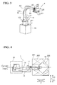
FIG. 7 is a bottom view of the robot hand of the depalletizing robot in the robot system according to the embodiment; -
FIG. 8 is a diagram showing how the robot hand in the robot system according to the embodiment holds a workpiece disposed approximately parallel to sides of a pallet; -
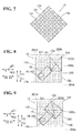
FIG. 9 is a diagram showing how the robot hand in the robot system according to the embodiment holds a workpiece disposed orthogonal to sides of a pallet; -
FIG. 10 is a diagram showing a state where the robot hand in the robot system according to the embodiment is at a right upper corner of the pallet; -
FIG. 11 is a diagram showing a state where the robot hand in the robot system according to the embodiment is at a left upper corner of the pallet; -
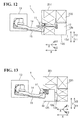
FIG. 12 is a diagram showing a state where the robot hand in the robot system according to the embodiment is at a right lower corner of the pallet; -
FIG. 13 is a diagram showing a state where the robot hand in the robot system according to the embodiment is at a left lower corner of the pallet; -
FIG. 14 is a perspective view of a detection robot in the robot system according to the embodiment; -
FIG. 15 is a plan view of a robot hand of the detection robot in the robot system according to the embodiment; -
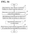
FIG. 16 is a flowchart of operations of the robot system according to the embodiment; -
FIG. 17 is a diagram illustrating an operation of placing a workpiece and an operation of detecting an arrangement state of the workpiece by the robot system according to the embodiment; -
FIG. 18 is a diagram illustrating an operation of holding a workpiece by the robot system according to the embodiment; -
FIG. 19 is a plan view of a robot hand according to a first modification of the embodiment; and -
FIG. 20 is a plan view of a robot hand according to a second modification of the embodiment. - The embodiments will now be described with reference to the accompanying drawings, wherein like reference numerals designate corresponding or identical elements throughout the various drawings.
- First, a configuration of a
robot system 100 according to an embodiment will be described by referring toFIGs. 1 to 15 . - As shown in
FIG. 1 , therobot system 100 includes adepalletizing robot 1 and adetection robot 2. Thedetection robot 2 detects aworkpiece 200. Examples of thedepalletizing robot 1 and thedetection robot 2 include, but are not limited to, a perpendicularly articulated robot. Apallet 201 is disposed adjacent to (on an X1 direction side of) thedepalletizing robot 1 and thedetection robot 2. On thepallet 201, a plurality ofworkpieces 200 of different sizes and shapes are stacked. Examples of theworkpiece 200 include, but are not limited to, a box-shaped workpiece. Thepallet 201 has an approximately rectangular shaped portion (that is, a box-shape having walls). In plan view, the approximately rectangular shaped portion of thepallet 201 surrounds theworkpieces 200. Aconveyor 202 is disposed adjacent to (on a Y2 direction side of) thedepalletizing robot 1. Theconveyor 202 receives (and transfers) theworkpiece 200. Thepallet 201 is an example of the "workpiece placement stand". - As shown in
FIG. 2 , thedepalletizing robot 1 is coupled to arobot controller 3. Thedetection robot 2 is coupled to arobot controller 4. Therobot controller 3 and therobot controller 4 are coupled to a PLC (programmable logic controller) 5. ThePLC 5 is coupled to a PC (Personal Computer) 6. ThePC 6 controls an overall operation of therobot system 100. ThePC 6 is also coupled to a laserlight emitting device 7 and acamera 8. The laserlight emitting device 7 and thecamera 8 detect the arrangement state of theworkpiece 200. ThePC 6 is an example of the "controller". - As shown in
FIG. 3 , thedepalletizing robot 1 includes a robotmain body 11 and arobot hand 12. Therobot hand 12 is mounted on the distal end of the robotmain body 11 in order to suck and hold theworkpiece 200 placed on thepallet 201. The robotmain body 11 includes abase 13 and arobot arm 14. Thedepalletizing robot 1 includes acable 15 and other elements coupled to therobot arm 14. - The
base 13 is secured to an installation surface such as a floor, a wall, and a ceiling. Therobot arm 14 has five degrees of freedom. Therobot arm 14 includes a plurality of arm structures. Anarm structure 141 is coupled to the base 13 in a rotatable manner about a rotation axis A1, which is perpendicular to the installation surface. Anarm structure 142 is coupled to thearm structure 141 in a rotatable manner about a rotation axis A2, which is perpendicular to the rotation axis A1. Anarm structure 143 is coupled to thearm structure 142 in a rotatable manner about a rotation axis A3, which is parallel to the rotation axis A2. Anarm structure 144 is coupled to thearm structure 143 in a rotatable manner about a rotation axis A4, which is parallel to the rotation axis A3. Anarm structure 145 is coupled to thearm structure 144 in a rotatable manner about a rotation axis A5, which is perpendicular to the rotation axis A4. It is noted that "parallel" and "perpendicular", as used herein, are not only intended to mean precisely "parallel" and "perpendicular", respectively, but also intended more broadly to encompass slight differences from being "parallel" and "perpendicular". Each of the rotation axes A1 to A5 is equipped with a servo motor. Each servo motor includes an encoder to detect the rotation position of the servo motor. Each servo motor is coupled to therobot controller 3. Thus, each servo motor operates based on a command from therobot controller 3. - As shown in
FIG. 4 , in plan view, thedepalletizing robot 1 is asymmetric with respect to a center line C, which is aligned in an X direction, in which therobot arm 14 of thedepalletizing robot 1 extends, such that therobot arm 14 protrudes to one side (a Y1 direction side) of a Y direction. Similarly, thecable 15 also protrudes to the Y1 direction side. - As shown in
FIGs. 5 and 6 , a base portion (which is on an X2 direction side) of therobot hand 12 is coupled to the robot arm 14 (more specifically, to the arm structure 145) such that in plan view, a perpendicular turning axis A5 of the portion (that is, the arm structure 145) of therobot arm 14 to which the base portion of therobot hand 12 is coupled is apart from the geometrical center (the point A, which is the geometrical center of gravity) of therobot hand 12. Specifically, therobot hand 12 has an approximately square shape in plan view, and is coupled to therobot arm 14 at a position adjacent to acorner 12a of the base portion of the approximately square (including orthogonal sides) shape of therobot hand 12. - As shown in
FIG. 6 , in plan view, the base portion of therobot hand 12 coupled to therobot arm 14 is at a position offset from the geometrical center of the robot hand 12 (that is, from the point A) by a predetermined distance d in the Y direction (more specifically, to a Y2 direction), which is orthogonal to the X direction, in which therobot arm 14 extends. - As shown in
FIGs. 5 and7 , therobot hand 12 includes a plurality ofsuction devices 121 and a robot handmain body 122. The plurality ofsuction devices 121 hold theworkpiece 200 placed on thepallet 201 by gaseous suction force (or suction force). The plurality ofsuction devices 121 are mounted on the robot handmain body 122. Thesuction devices 121 of therobot hand 12 are each independently coupled to an air sucking tube (not shown). Air is inhaled through the tube and thus theworkpiece 200 is sucked (held) onto thesuction device 121. Thesuction devices 121 are coupled to the PLC 5 (seeFIG. 2 ). Through thePLC 5, thePC 6 controls ON and OFF of the air sucking operation of the suction devices 121 (that is, switches between operation mode and nonoperation mode). In this embodiment, as shown inFIG. 7 , thesuction devices 121 are approximately evenly disposed over the surface of the robot hand 12 (robot hand main body 122) in plan view. Specifically, 41suction devices 121 are disposed over the surface of the robot handmain body 122 in a houndstooth pattern. More specifically, fivesuction devices 121, foursuction devices 121, fivesuction devices 121, foursuction devices 121, fivesuction devices 121, foursuction devices 121, fivesuction devices 121, foursuction devices 121, and fivesuction devices 121 are arranged along the sides of the approximately square shape of the robot handmain portion 122. ThePC 6 controls each of the 41suction devices 121 to independently switch between operation mode and nonoperation mode. Thesuction device 121 is an example of the "holder". - As shown in
FIGs. 8 and 9 , in this embodiment, thePC 6 controls therobot hand 12 to hold theworkpiece 200 while controlling thesuction devices 121 to switch between operation mode and nonoperation mode independently from each other in accordance with the shape (such as rectangular shape) or the size (such as the area of theworkpiece 200 in plan view) of theworkpiece 200. Specifically, thePC 6 controls at least onesuction device 121 among thesuction devices 121 to switch to operation mode, the at least onesuction device 121 being disposed in a portion of therobot hand 12 overlapping theworkpiece 200, controls the at least onesuction device 121 to hold theworkpiece 200, and controls the rest of thesuction devices 121 to switch to nonoperation mode. When asuction device 121 partially overlaps theworkpiece 200, it is possible to switchsuch suction device 121 into either operation mode or nonoperation mode. It is also possible to switch asuction device 121 to operation mode when equal to or larger than a predetermined area of thesuction device 121 overlaps theworkpiece 200. - In this embodiment, based on an image of the
workpiece 200 captured by thecamera 8 of therobot 2, thePC 6 controls at least onesuction device 121 among thesuction devices 121 to switch to operation mode, the at least onesuction device 121 being disposed in a portion of therobot hand 12 overlapping theworkpiece 200, controls the at least onesuction device 121 to hold theworkpiece 200, and controls the rest of thesuction devices 121 to switch to nonoperation mode. When theworkpiece 200 is smaller than therobot hand 12 in plan view as shown inFIG. 8 , thosesuction devices 121 disposed in the portion of therobot hand 12 overlapping theworkpiece 200 switch to operation mode. When theworkpiece 200 is larger than therobot hand 12 in plan view, all thesuction devices 121 switch to operation mode. The portion of therobot hand 12 where thosesuction devices 121 to switch to operation mode are disposed is a portion where therobot hand 12 keeps overlapping theworkpiece 200 for the period of time from when theworkpiece 200 is held until when theworkpiece 200 is placed onto theconveyer 202. - As show in
FIG. 8 , whensides workpiece 200 are respectively approximately parallel tosides pallet 201, therobot arm 14 moves (rotates) theworkpiece 200 in the following manner to hold theworkpiece 200. In plan view, twoorthogonal sides 12b and 12c (outer edges) of therobot hand 12 at the distal end of therobot hand 12 respectively overlap thesides workpiece 200. At the same time, in plan view, acorner 12d of therobot hand 12 at the distal end of therobot hand 12 overlaps a corner 200c of theworkpiece 200. Even when theworkpiece 200 is disposed in the vicinity of a corner or the center of the pallet, theworkpiece 200 is held such that the twosides 12b and 12c (outer edges) of therobot hand 12 overlap two of the four sides of theworkpiece 200, and such that thecorner 12d of therobot hand 12 at the distal end of therobot hand 12 overlaps one of the four corners of theworkpiece 200. - As shown in
FIG. 9 , when the four sides of theworkpiece 200 are orthogonal to the twosides pallet 201, therobot arm 14 moves (rotates) theworkpiece 200 in the following manner to hold theworkpiece 200. In plan view, the twoorthogonal sides 12b and 12c (outer edges) of therobot hand 12 at the distal end of therobot hand 12 overlap the twocorners 200c and 200d of theworkpiece 200. - As shown in
FIGs. 10 to 13 , thePC 6 controls therobot hand 12 to hold theworkpiece 200 placed on thepallet 201 while controlling therobot arm 14 to turn thesuction devices 121 such that the distal ends of thesuction devices 121 are oriented in a direction (E1 or E2 direction) crossing the X direction, in which therobot arm 14 extends. - As shown in
FIG. 14 , therobot 2 includes a robotmain body 21 and arobot hand 22. Therobot hand 22 is mounted on the distal end of the robotmain body 21. The robotmain body 21 includes abase 23 and arobot arm 24. - The
base 23 is secured to an installation surface such as a floor, a wall, and a ceiling. Therobot arm 24 has six degrees of freedom. Therobot arm 24 includes a plurality of arm structures. Anarm structure 241 is coupled to the base 23 in a rotatable manner about a rotation axis B1, which is perpendicular to the installation surface. Anarm structure 242 is coupled to thearm structure 241 in a rotatable manner about a rotation axis B2, which is perpendicular to the rotation axis B1. Anarm structure 243 is coupled to thearm structure 242 in a rotatable manner about a rotation axis B3, which is parallel to the rotation axis B2. Anarm structure 244 is coupled to thearm structure 243 in a rotatable manner about a rotation axis B4, which is perpendicular to the rotation axis B3. Anarm structure 245 is coupled to thearm structure 244 in a rotatable manner about a rotation axis B5, which is perpendicular to the rotation axis B4. Anarm structure 246 is coupled to thearm structure 245 in a rotatable manner about a rotation axis B6, which is perpendicular to the rotation axis B5. It is noted that "parallel" and "perpendicular", as used herein, are not only intended to mean precisely "parallel" and "perpendicular", respectively, but also intended more broadly to encompass slight differences from being "parallel" and "perpendicular". Each of the rotation axes B1 to B6 is equipped with a servo motor (joint). Each servo motor includes an encoder to detect the rotation position of the servo motor. Each servo motor is coupled to therobot controller 4. Thus, each servo motor operates based on a command from therobot controller 4. Therobot arm 24 is an example of the "second robot arm". - As shown in
FIG. 15 , therobot hand 22 includes the laserlight emitting device 7 and the camera 8 (that is, a stereoscopic camera). The laserlight emitting device 7 emits laser light to theworkpiece 200. Thecamera 8 detects the laser light reflected from theworkpiece 200. The laserlight emitting device 7 is an example of the "detector". Thecamera 8 is an example of the "detector" and the "image capture device". The laserlight emitting device 7 emits, for example, cross-shaped laser light (that is, laser light crossing each other) to theworkpiece 200. At the same time, thecamera 8 detects (that is, captures an image of) the laser light reflected from theworkpiece 200. Then, based on the detection result (that is, the captured image), thePC 6 calculates (or measures) an arrangement state of the workpiece 200 (such as the height of the workpiece 200 (more specifically, the height position of the upper surface of the workpiece 200), and the rotational angle, position, shape, and size of the workpiece 200). Then, in this embodiment, thePC 6 controls therobot arm 14 to move based on the arrangement state of theworkpiece 200 detected by the laserlight emitting device 7 and thecamera 8, and controls therobot hand 12 to hold theworkpiece 200 placed on thepallet 201. - Next, operations of the
robot system 100 according to this embodiment will be described by referring toFIGs. 16 to 18 . - First, as shown in
FIG. 16 , at step S1, based on the latest detection operation by the laserlight emitting device 7 and thecamera 8 detecting the arrangement state of theworkpiece 200 disposed on the uppermost level of thepallet 201, therobot hand 12 of therobot arm 14 holds theworkpiece 200, and therobot arm 14 moves to place theworkpiece 200 onto theconveyor 202, as shown inFIG. 17 . - Simultaneously with the placement operation of the
workpiece 200 by the robot arm 14 (or simultaneously with the transfer operation of the workpiece 200), therobot arm 24 moves to arrange the robot hand 22 (the laserlight emitting device 7 and the camera 8), which are mounted on therobot arm 24, over thepallet 201. - Then, at step S2, the laser
light emitting device 7 emits laser light to theworkpiece 200, and thecamera 8 captures an image of the laser light reflected from theworkpiece 200 so as to detect an arrangement state (such as height, shape, and size) of aworkpiece 200 next to be held on thepallet 201. Then, the next-to-be-held workpiece 200 (which is, for example, disposed on the uppermost level) is selected among a plurality of detectedworkpieces 200. Here, a selection is also made as to whichsuction devices 121 to switch to operation mode and which suctiondevices 121 to switch to nonoperation mode at step S5, described later. - Next, at step S3, as shown in
FIG. 18 , therobot arm 14 moves to a position over thepallet 201. Then, simultaneously with the movement operation of therobot arm 14, therobot arm 24 is withheld in a direction apart from thepallet 201 from the position adjacent to thepallet 201 in order to avoid collision with therobot arm 14. - Next, at step S4, when the
workpiece 200 to be held is disposed on, for example, the Y2 direction side (or on the Y1 direction side), which is orthogonal to the X direction, then as shown inFIGs. 10 and 11 (orFIGs. 12 and 13 ), therobot arm 14 turns therobot hand 12 by approximately 45 degrees to the Y2 direction side (or to the Y1 direction side) from a basic state (seeFIG. 4 ). Then, therobot hand 12 moves to a position over the next-to-be-held workpiece 200. Then, at step S5, therobot hand 12 holds theworkpiece 200 such that in plan view, at least onesuction device 121 among thesuction devices 121 that is disposed in a portion of therobot hand 12 overlapping theworkpiece 200 switches to operation mode, while the rest of thesuction devices 121 switch to nonoperation mode. Then, the processing returns to step S1, where theworkpiece 200 is placed onto theconveyor 202. After theworkpiece 200 is placed on theconveyor 202, all thesuction devices 121 are switched to nonoperation mode. - Then, the operations at steps S1 to S5 are repeated until no
workpieces 200 are left in thepallet 201, and thus the depalletizing processing of theworkpieces 200 by therobot hand 12 completes. - As has been described hereinbefore, in this embodiment, the
PC 6 controls therobot hand 12 to hold theworkpiece 200 while controlling thesuction devices 121 to switch between operation mode and nonoperation mode in accordance with the shape or the size of theworkpiece 200. This enables thesuction devices 121 to switch to operation mode in accordance with the shape or the size of theworkpiece 200. This, in turn, ensures holding of anyworkpieces 200 that vary in shape and/or size. - In this embodiment, as described above, the
PC 6 controls at least onesuction device 121 among thesuction devices 121 to switch to operation mode, the at least onesuction device 121 being disposed in a portion of therobot hand 12 overlapping theworkpiece 200 in plan view, controls the at least onesuction device 121 to hold theworkpiece 200, and controls the rest of thesuction devices 121 to switch to nonoperation mode. Thus, thesuction devices 121 readily match the shape or the size of theworkpiece 200 by switching thesuction devices 121 to operation mode. This facilitates holding of anyworkpieces 200 that vary in shape and/or size. When therobot system 100 has a limited amount of air suction, it is possible to control thosesuction devices 121 disposed in portions of therobot hand 12 other than the portion overlapping theworkpiece 200 to switch to nonoperation mode. This increases the amount of air suction on thesuction devices 121 in operation mode and enhances the suction force of thesuction devices 121 in operation mode. - Also in this embodiment, as described above, the laser
light emitting device 7 and thecamera 8 detect the shape or the size of theworkpiece 200 placed on thepallet 201. ThePC 6 controls therobot hand 12 to hold theworkpiece 200 while controlling thesuction devices 121 to switch between operation mode and nonoperation mode in accordance with the shape or the size of theworkpiece 200 detected by the laserlight emitting device 7 and thecamera 8. Thus, the laserlight emitting device 7 and thecamera 8 detect the shape or the size of theworkpiece 200, and in accordance with the shape or the size of theworkpiece 200, thesuction devices 121 are readily switched between operation mode and nonoperation mode. - Also in this embodiment, as described above, based on an image of the
workpiece 200 captured by thecamera 8, thePC 6 controls at least onesuction device 121 among thesuction devices 121 to switch to operation mode, the at least onesuction device 121 being disposed in a portion of therobot hand 12 overlapping theworkpiece 200, controls the at least onesuction device 121 to hold theworkpiece 200, and controls the rest of thesuction devices 121 to switch to nonoperation mode. Thus, the shape or the size of theworkpiece 200 is readily detected based on the image of theworkpiece 200 captured by thecamera 8. - Also in this embodiment, as described above, the
PC 6 controls each of thesuction devices 121 to independently switch between operation mode and nonoperation mode. Thus, thesuction devices 121 readily switch to operation mode or nonoperation mode in accordance with the shape or the size of theworkpiece 200. - Also in this embodiment, as described above, the
PC 6 controls therobot hand 12 to hold theworkpiece 200 while controlling therobot hand 12 to rotate such that the two orthogonal sides of therobot hand 12 at the distal end of therobot hand 12 are respectively approximately parallel to two sides of thepallet 201, and while controlling thesuction devices 121 to switch between operation mode and nonoperation mode in accordance with the shape of theworkpiece 200. Thus, even when an approximatelyrectangular workpiece 200 is disposed at a corner of the approximately rectangular shaped portion of thepallet 201, the outer edge of therobot hand 12 can be disposed along the outer edge of the approximately rectangular shape of theworkpiece 200. Thus, theworkpiece 200 can be held with therobot hand 12 overlapping theworkpiece 200. - Also in this embodiment, as described above, the
suction devices 121 are approximately evenly disposed over the surface of therobot hand 12 in plan view. Thus, as opposed to the case where thesuction devices 121 are unevenly disposed over the surface of therobot hand 12, theworkpiece 200 is reliably held at any position of therobot hand 12 with thesuction devices 121 overlapping theworkpiece 200. - Obviously, numerous modifications and variations of the present disclosure are possible in light of the above teachings. It is therefore to be understood that within the scope of the appended claims, the present disclosure may be practiced otherwise than as specifically described herein.
- For example, the above-described embodiment has been illustrated as using two robots, namely, the depalletizing robot having five degrees of freedom and the detection robot having six degrees of freedom to detect an arrangement state of the workpiece disposed on the pallet and to hold and transfer the workpiece. It is also possible to use a single two-arm robot to detect an arrangement state of the workpiece disposed on the pallet and to hold and transfer the workpiece. The number of control axes for each of the depalletizing robot and the detection robot is selectable conveniently. For example, it is possible to use a robot arm having four degrees of freedom or a robot arm having more than four degrees of freedom for each of the depalletizing robot and the detection robot.
- Also in the above-described embodiment, suction force is used to hold the workpiece. It is also possible to use electromagnetic force (that is, magnetic force using a magnet) to hold the workpiece.
- Also in the above-described embodiment, 41 suction devices are provided on the robot hand. The robot hand may include any other number of the suction devices than 41.
- Also in the above-described embodiment, the workpiece is held such that at least one suction device among the suction devices that is disposed in a portion of the robot hand overlapping the workpiece in plan view switches to operation mode, and the rest of the suction devices switch to nonoperation mode. Another possible example is that some of the suction devices disposed in the portion of the robot hand overlapping the workpiece switch to nonoperation mode.
- Also in the above-described embodiment, the portion of the robot hand where the suction devices to switch to operation mode are disposed is a portion where the robot hand keeps overlapping the workpiece for the period of time from when the workpiece is held until when the workpiece is placed onto the conveyer. Another possible example is that at the start of holding of the workpiece, some of the suction devices (suction devices disposed in the vicinity of the outer edge of the workpiece) disposed in the portion of the robot hand overlapping the workpiece switch to nonoperation mode, and then all the suction devices disposed in the portion of the robot hand overlapping the workpiece switch operation mode. This eliminates or minimizes erroneous holding of a workpiece adjacent to the workpiece actually to be held.
- Also in the above-described embodiment, the suction devices switch between operation mode and nonoperation mode in accordance with the shape or the size of the workpiece detected by the laser light emitting device and the camera. Another possible example is that when the shape or the size of the workpiece is known in advance, it is not necessary to provide the laser light emitting device and the camera; the suction devices may switch between operation mode and nonoperation mode based on the known shape or size of the workpiece.
- Also in the above-described embodiment, each of the suction devices is independently switchable between operation mode and nonoperation mode. Another possible example is to switch a unit of a predetermined number of suction devices (for example, each set of four suction devices) between operation mode and nonoperation mode. This facilitates the switching control of the plurality of suction devices.
- Also in the above-described embodiment, the suction devices are arranged in a houndstooth pattern over the surface of the robot hand. Another possible example is to arrange the suction devices in a matrix.
- Also in the above-described embodiment, the workpiece is held at the distal end of the robot hand. Another possible example is to hold the workpiece at the center of the robot hand.
- Also in the above-described embodiment, the robot hand has been illustrated as having an approximately square shape in plan view. Another possible example is a
robot hand 31 according to a first modification shown inFIG. 19 . In plan view, therobot hand 31 has an approximately triangular shape having two sides orthogonal to each other at the distal end portion of therobot hand 31. Still another possible example is arobot hand 32 according to a second modification shown inFIG. 20 . Therobot hand 32 has an approximately hexagonal shape having two sides orthogonal to each other at the distal end portion of therobot hand 32. The robot hand may also have a shape other than a polygonal shape such as an approximately square shape (examples including, but not limited to, an elliptical shape). Also in these modifications, at least one suction device among the suction devices that is disposed in the portion of the robot hand overlapping the workpiece switch to operation mode, and the rest of the suction devices switch to nonoperation mode. - Also in the above-described embodiment, a depalletizing operation has been illustrated, in which the workpieces stacked on the pallet are depalletized by the robot system. The robot system may also perform an operation other than the depalletizing operation, examples including, but not limited to, a palletizing operation.
- Also in the above-described embodiment, the PC has been illustrated as controlling the operation of the robot (the robot system). It is also possible to use a PLC or a robot controller to control the operation of the robot.
- 6
- PC (Controller)
- 7
- Laser light emitting device (detector)
- 8
- Camera (detector, image capture device)
- 12, 31, 32
- Robot hand
- 12b, 12c
- Side
- 100
- Robot system
- 121
- Suction device (holder)
- 200
- Workpiece
- 201
- Pallet (workpiece placement stand)
- 201a, 201b
- Side
Claims (8)
- A robot system 100, characterized by:a robot hand 12, 31, 32 comprising a plurality of holders 121 configured to hold a workpiece placed on a workpiece placement stand 201 using at least one of electromagnetic force and suction force; anda controller 6 configured to control the plurality of holders 121 to hold the workpiece while controlling the plurality of holders 121 to switch between operation mode and nonoperation mode in accordance with at least one of a shape and a size of the workpiece.
- The robot system 100 according to claim 1, wherein the controller 6 is configured to control at least one holder 121 among the plurality of holders 121 to switch to operation mode, the at least one holder 121 being disposed in a portion of the robot hand 12, 31, 32 overlapping the workpiece, configured to control the at least one holder 121 to hold the workpiece, and configured to control a rest of the plurality of holders 121 to switch to nonoperation mode.
- The robot system 100 according to claim 1 or 2, further comprising a detector 7, 8 configured to detect the shape or the size of the workpiece placed on the workpiece placement stand 201,
wherein the controller 6 is configured to control the robot hand 12, 31, 32 to hold the workpiece while controlling the plurality of holders 121 to switch between operation mode and nonoperation mode in accordance with at least one of the shape and the size of the workpiece detected by the detector 7, 8. - The robot system 100 according to claim 3,
wherein the detector 7, 8 comprises an image capture device 8 configured to capture an image of the workpiece, and
wherein based on the image of the workpiece captured by the image capture device 8, the controller 6 is configured to control at least one holder 121 among the plurality of holders 121 to switch to operation mode, the at least one holder 121 being disposed in a portion of the robot hand 12, 31, 32 overlapping the workpiece, configured to control the at least one holder 121 to hold the workpiece, and configured to control a rest of the plurality of holders 121 to switch to nonoperation mode. - The robot system 100 according to any one of claims 1 to 4, wherein the controller 6 is configured to control each of the plurality of holders 121 to independently switch between operation mode and nonoperation mode.
- The robot system 100 according to any one of claims 1 to 5,
wherein the workpiece placement stand comprises an approximately rectangular shaped portion surrounding the workpiece,
wherein the robot hand 12, 31, 32 comprises a portion having two approximately orthogonal sides at a distal end of the robot hand 12, 31, 32, and
wherein the controller 6 is configured to control the robot hand 12, 31, 32 to hold the workpiece while controlling the robot hand 12, 31, 32 to rotate such that the two approximately orthogonal sides of the robot hand 12, 31, 32 are respectively approximately parallel to two sides of the workpiece placement stand 201, and while controlling the plurality of holders 121 to switch between operation mode and nonoperation mode in accordance with the shape of the workpiece. - The robot system 100 according to any one of claims 1 to 6, wherein the plurality of holders 121 are approximately evenly disposed over a surface of the robot hand 12, 31, 32.
- A method for transferring a workpiece, characterized by:switching a plurality of holders 121 between operation mode and nonoperation mode in accordance with at least one of a shape and a size of the workpiece, the plurality of holders 121 being mounted on a robot hand 12, 31, 32 and configured to hold the workpiece placed on a workpiece placement stand 201 using at least one of electromagnetic force and suction force; andholding the workpiece while controlling the plurality of holders 121 to switch between operation mode and nonoperation mode.
Applications Claiming Priority (1)
| Application Number | Priority Date | Filing Date | Title |
|---|---|---|---|
| JP2013052167A JP2014176926A (en) | 2013-03-14 | 2013-03-14 | Robot system and method for conveying work |
Publications (2)
| Publication Number | Publication Date |
|---|---|
| EP2783801A2 true EP2783801A2 (en) | 2014-10-01 |
| EP2783801A3 EP2783801A3 (en) | 2015-03-04 |
Family
ID=50189584
Family Applications (1)
| Application Number | Title | Priority Date | Filing Date |
|---|---|---|---|
| EP14157417.8A Withdrawn EP2783801A3 (en) | 2013-03-14 | 2014-03-03 | Robot system and method for transferring workpiece |
Country Status (4)
| Country | Link |
|---|---|
| US (1) | US20140277721A1 (en) |
| EP (1) | EP2783801A3 (en) |
| JP (1) | JP2014176926A (en) |
| CN (1) | CN104044151A (en) |
Cited By (2)
| Publication number | Priority date | Publication date | Assignee | Title |
|---|---|---|---|---|
| US10315865B2 (en) * | 2015-11-12 | 2019-06-11 | Kabushiki Kaisha Toshiba | Conveying device, conveying system, and conveying method |
| WO2021045944A1 (en) * | 2019-09-04 | 2021-03-11 | The Steelastic Company, Llc | Transfer tooling for varying tire belt sizes |
Families Citing this family (31)
| Publication number | Priority date | Publication date | Assignee | Title |
|---|---|---|---|---|
| US9205558B1 (en) * | 2014-07-16 | 2015-12-08 | Google Inc. | Multiple suction cup control |
| JP6486114B2 (en) * | 2015-01-16 | 2019-03-20 | 株式会社東芝 | Handling equipment |
| JP6034892B2 (en) * | 2015-01-27 | 2016-11-30 | ファナック株式会社 | A robot system in which the brightness of the robot mount changes |
| CN104723325B (en) * | 2015-03-17 | 2016-04-20 | 南京理工大学 | A kind of feeding mechanical hand for automatic production line |
| CN104760826B (en) * | 2015-04-13 | 2017-12-19 | 上海金东唐科技有限公司 | Automatic fine tuning test equipment |
| NL2014635B1 (en) * | 2015-04-14 | 2017-01-20 | Vmi Holland Bv | Gripper, gripper assembly and method for gripping a tire component. |
| CN105522565A (en) * | 2016-01-26 | 2016-04-27 | 中塑联新材料科技湖北有限公司 | Mechanical arm for stacking plastic plates or plastic sheets |
| US10221015B2 (en) * | 2016-06-27 | 2019-03-05 | Amazon Technologies, Inc. | Automated item singulation |
| JP2018122945A (en) * | 2017-01-30 | 2018-08-09 | 株式会社東芝 | Variable type article holding device, transferring device, robot handling system, and method of controlling transferring device |
| NL2018380B1 (en) * | 2017-02-15 | 2018-09-06 | Vmi Holland Bv | Transfer device and method for transferring a tire component |
| CN106829462A (en) * | 2017-03-07 | 2017-06-13 | 河南摩西机械制造有限公司 | A kind of iron pan conveying robot |
| JP2018203480A (en) * | 2017-06-07 | 2018-12-27 | 株式会社東芝 | Sorting apparatus and sorting system |
| CN107253227A (en) * | 2017-07-25 | 2017-10-17 | 广州锦湖自动化设备有限公司 | Automatic shearing eyeglass machine |
| JP7109904B2 (en) | 2017-11-02 | 2022-08-01 | 株式会社東芝 | take-out system |
| JP6917920B2 (en) | 2018-02-19 | 2021-08-11 | 株式会社東芝 | Transport system and transport method |
| JP7000213B2 (en) * | 2018-03-19 | 2022-01-19 | 株式会社東芝 | Retention device, transport system, controller, and retention method |
| JP6937260B2 (en) * | 2018-03-19 | 2021-09-22 | 株式会社東芝 | Grip control device, grip system, and program |
| DE102018208126A1 (en) * | 2018-05-23 | 2019-11-28 | Trumpf Werkzeugmaschinen Gmbh + Co. Kg | Method for handling a workpiece with the aid of a removal tool and machine for carrying out the method |
| JP7141288B2 (en) * | 2018-09-25 | 2022-09-22 | 川崎重工業株式会社 | robot system |
| US10335947B1 (en) * | 2019-01-18 | 2019-07-02 | Mujin, Inc. | Robotic system with piece-loss management mechanism |
| JP7211208B2 (en) * | 2019-03-28 | 2023-01-24 | 株式会社Ihi | Depalletizing device and depalletizing method |
| JP6958593B2 (en) * | 2019-05-29 | 2021-11-02 | 村田機械株式会社 | Transfer device |
| US11345029B2 (en) * | 2019-08-21 | 2022-05-31 | Mujin, Inc. | Robotic multi-gripper assemblies and methods for gripping and holding objects |
| CN112405570A (en) | 2019-08-21 | 2021-02-26 | 牧今科技 | Robotic multi-gripper assembly and method for gripping and holding objects |
| CN111993448B (en) * | 2019-08-21 | 2022-02-08 | 牧今科技 | Robotic multi-gripper assembly and method for gripping and holding objects |
| JP7123885B2 (en) * | 2019-09-13 | 2022-08-23 | 株式会社東芝 | Handling device, control device and holding method |
| TWI702179B (en) * | 2019-12-05 | 2020-08-21 | 所羅門股份有限公司 | Fetching system and method |
| JP7467951B2 (en) | 2020-02-03 | 2024-04-16 | 株式会社デンソーウェーブ | Workpiece suction device |
| KR102169074B1 (en) * | 2020-03-19 | 2020-10-22 | 주식회사 에이스로보테크 | Robot for connecting rod transfer using electromagnet |
| JP7457546B2 (en) | 2020-03-23 | 2024-03-28 | 株式会社日立オートメーション | robot hand |
| CN114311007A (en) * | 2022-01-14 | 2022-04-12 | 上海交通大学 | Flexible electromagnet gripper for grabbing steel plate |
Citations (1)
| Publication number | Priority date | Publication date | Assignee | Title |
|---|---|---|---|---|
| JP2001317911A (en) | 2000-05-02 | 2001-11-16 | Daifuku Co Ltd | Work position recognizing apparatus |
Family Cites Families (13)
| Publication number | Priority date | Publication date | Assignee | Title |
|---|---|---|---|---|
| JPS59152089A (en) * | 1983-02-16 | 1984-08-30 | 株式会社ブリヂストン | Hand for industrial robot |
| JPS61214989A (en) * | 1985-03-15 | 1986-09-24 | 三菱電機株式会社 | Hand device for industrial robot |
| JPH0727135Y2 (en) * | 1990-05-18 | 1995-06-21 | 株式会社名機製作所 | Unloader for molding machine |
| JP2530420Y2 (en) * | 1990-10-31 | 1997-03-26 | 株式会社テクノクリート | Demolding device |
| JP3448413B2 (en) * | 1995-12-11 | 2003-09-22 | 株式会社リコー | Coordinate correction device for horizontal articulated robot |
| JPH09285986A (en) * | 1996-04-23 | 1997-11-04 | Ricoh Co Ltd | End effector |
| JPH10120354A (en) * | 1996-10-21 | 1998-05-12 | Amada Co Ltd | Selective operating system of vacuum pad for plate work |
| JP2000127074A (en) * | 1998-10-23 | 2000-05-09 | Tsubakimoto Chain Co | Grasping device |
| KR100456858B1 (en) * | 2002-12-18 | 2004-11-10 | 현대자동차주식회사 | A vertical shaft adjusting apparatus by multi steps at an attachment |
| JP4112570B2 (en) * | 2004-05-21 | 2008-07-02 | ファナック株式会社 | Striated structure of industrial robot |
| JP5190838B2 (en) * | 2007-09-28 | 2013-04-24 | 株式会社ユーシン精機 | Gripping tool |
| JP2010005769A (en) * | 2008-06-30 | 2010-01-14 | Ihi Corp | Depalletizing apparatus and depalletizing method |
| TW201115678A (en) * | 2009-10-30 | 2011-05-01 | Sun Yueh Way | Panel suction unit and panel suction assembly having the same |
-
2013
- 2013-03-14 JP JP2013052167A patent/JP2014176926A/en active Pending
-
2014
- 2014-01-07 CN CN201410006635.2A patent/CN104044151A/en active Pending
- 2014-03-03 EP EP14157417.8A patent/EP2783801A3/en not_active Withdrawn
- 2014-03-14 US US14/210,446 patent/US20140277721A1/en not_active Abandoned
Patent Citations (1)
| Publication number | Priority date | Publication date | Assignee | Title |
|---|---|---|---|---|
| JP2001317911A (en) | 2000-05-02 | 2001-11-16 | Daifuku Co Ltd | Work position recognizing apparatus |
Cited By (3)
| Publication number | Priority date | Publication date | Assignee | Title |
|---|---|---|---|---|
| US10315865B2 (en) * | 2015-11-12 | 2019-06-11 | Kabushiki Kaisha Toshiba | Conveying device, conveying system, and conveying method |
| WO2021045944A1 (en) * | 2019-09-04 | 2021-03-11 | The Steelastic Company, Llc | Transfer tooling for varying tire belt sizes |
| CN114364522A (en) * | 2019-09-04 | 2022-04-15 | 斯第莱斯梯克有限公司 | Transfer tool for different tire belt sizes |
Also Published As
| Publication number | Publication date |
|---|---|
| EP2783801A3 (en) | 2015-03-04 |
| US20140277721A1 (en) | 2014-09-18 |
| CN104044151A (en) | 2014-09-17 |
| JP2014176926A (en) | 2014-09-25 |
Similar Documents
| Publication | Publication Date | Title |
|---|---|---|
| EP2783801A2 (en) | Robot system and method for transferring workpiece | |
| US9352463B2 (en) | Robot system and method for transferring workpiece | |
| EP2711144A1 (en) | Robot system and workpiece transfer method | |
| JP6942576B2 (en) | Transport device | |
| JP5304469B2 (en) | Bin picking system | |
| JP7117193B2 (en) | ROBOT AND ROBOT SYSTEM INCLUDING THE SAME | |
| JP7117192B2 (en) | Robot hands, robots and robot systems | |
| EP2578365A2 (en) | Robot system and method for producing a to-be-processed material | |
| US20130085604A1 (en) | Robot apparatus, robot system, and method for producing a to-be-processed material | |
| KR101952767B1 (en) | Robot | |
| JP7186546B2 (en) | Transfer device | |
| JP5522298B2 (en) | Bin picking system | |
| JP5535884B2 (en) | Work removal method | |
| JP2019042828A (en) | Picking facility | |
| JP2019151421A (en) | Article transfer device and loading position detection device | |
| CN117355392A (en) | Integrated mobile manipulator robot | |
| JP2023115274A (en) | Extracting device | |
| JP2020044588A (en) | Article moving device and end effector for robot arm | |
| WO2020100908A1 (en) | Article loading facility | |
| JP2014061561A (en) | Robot system and article manufacturing method | |
| CN115485217A (en) | Position setting device for setting position of stacked workpiece and robot device provided with position setting device | |
| WO2023127373A1 (en) | Robot system | |
| JP7192682B2 (en) | inspection system | |
| WO2023101027A1 (en) | Control device for substrate transport robot, and method for controlling joint motor | |
| JP2022148679A (en) | Transfer device and transfer method |
Legal Events
| Date | Code | Title | Description |
|---|---|---|---|
| 17P | Request for examination filed |
Effective date: 20140303 |
|
| AK | Designated contracting states |
Kind code of ref document: A2 Designated state(s): AL AT BE BG CH CY CZ DE DK EE ES FI FR GB GR HR HU IE IS IT LI LT LU LV MC MK MT NL NO PL PT RO RS SE SI SK SM TR |
|
| AX | Request for extension of the european patent |
Extension state: BA ME |
|
| PUAI | Public reference made under article 153(3) epc to a published international application that has entered the european phase |
Free format text: ORIGINAL CODE: 0009012 |
|
| PUAL | Search report despatched |
Free format text: ORIGINAL CODE: 0009013 |
|
| AK | Designated contracting states |
Kind code of ref document: A3 Designated state(s): AL AT BE BG CH CY CZ DE DK EE ES FI FR GB GR HR HU IE IS IT LI LT LU LV MC MK MT NL NO PL PT RO RS SE SI SK SM TR |
|
| AX | Request for extension of the european patent |
Extension state: BA ME |
|
| RIC1 | Information provided on ipc code assigned before grant |
Ipc: B25J 9/16 20060101AFI20150129BHEP |
|
| STAA | Information on the status of an ep patent application or granted ep patent |
Free format text: STATUS: THE APPLICATION IS DEEMED TO BE WITHDRAWN |
|
| 18D | Application deemed to be withdrawn |
Effective date: 20150905 |