EP2779381B1 - Process for annealing of helical wound cores used for automotive alternator applications - Google Patents
Process for annealing of helical wound cores used for automotive alternator applications Download PDFInfo
- Publication number
- EP2779381B1 EP2779381B1 EP13162496.7A EP13162496A EP2779381B1 EP 2779381 B1 EP2779381 B1 EP 2779381B1 EP 13162496 A EP13162496 A EP 13162496A EP 2779381 B1 EP2779381 B1 EP 2779381B1
- Authority
- EP
- European Patent Office
- Prior art keywords
- core
- iron
- annealing
- strip
- helically wound
- Prior art date
- Legal status (The legal status is an assumption and is not a legal conclusion. Google has not performed a legal analysis and makes no representation as to the accuracy of the status listed.)
- Not-in-force
Links
- 238000000034 method Methods 0.000 title claims description 30
- 238000000137 annealing Methods 0.000 title claims description 24
- 230000008569 process Effects 0.000 title description 4
- XEEYBQQBJWHFJM-UHFFFAOYSA-N iron Substances [Fe] XEEYBQQBJWHFJM-UHFFFAOYSA-N 0.000 claims description 29
- 229910052742 iron Inorganic materials 0.000 claims description 29
- 238000003475 lamination Methods 0.000 claims description 20
- 238000004804 winding Methods 0.000 claims description 19
- 238000004519 manufacturing process Methods 0.000 claims description 18
- 238000005452 bending Methods 0.000 claims description 12
- 229910000976 Electrical steel Inorganic materials 0.000 claims description 11
- 238000003466 welding Methods 0.000 claims description 11
- 238000001953 recrystallisation Methods 0.000 claims description 5
- 238000007373 indentation Methods 0.000 claims description 3
- 239000000463 material Substances 0.000 claims description 3
- 230000007935 neutral effect Effects 0.000 claims description 3
- 230000002093 peripheral effect Effects 0.000 claims description 3
- 229910000831 Steel Inorganic materials 0.000 description 24
- 239000010959 steel Substances 0.000 description 24
- 230000000694 effects Effects 0.000 description 6
- 230000006698 induction Effects 0.000 description 5
- IJGRMHOSHXDMSA-UHFFFAOYSA-N Atomic nitrogen Chemical compound N#N IJGRMHOSHXDMSA-UHFFFAOYSA-N 0.000 description 4
- 230000004907 flux Effects 0.000 description 4
- 238000001000 micrograph Methods 0.000 description 4
- RYGMFSIKBFXOCR-UHFFFAOYSA-N Copper Chemical compound [Cu] RYGMFSIKBFXOCR-UHFFFAOYSA-N 0.000 description 2
- ATUOYWHBWRKTHZ-UHFFFAOYSA-N Propane Chemical compound CCC ATUOYWHBWRKTHZ-UHFFFAOYSA-N 0.000 description 2
- 238000013459 approach Methods 0.000 description 2
- 230000015556 catabolic process Effects 0.000 description 2
- 230000006835 compression Effects 0.000 description 2
- 238000007906 compression Methods 0.000 description 2
- 230000007423 decrease Effects 0.000 description 2
- 238000006731 degradation reaction Methods 0.000 description 2
- 238000013461 design Methods 0.000 description 2
- 230000002500 effect on skin Effects 0.000 description 2
- 230000006872 improvement Effects 0.000 description 2
- VNWKTOKETHGBQD-UHFFFAOYSA-N methane Chemical compound C VNWKTOKETHGBQD-UHFFFAOYSA-N 0.000 description 2
- 229910052757 nitrogen Inorganic materials 0.000 description 2
- 230000008092 positive effect Effects 0.000 description 2
- 239000004215 Carbon black (E152) Substances 0.000 description 1
- UFHFLCQGNIYNRP-UHFFFAOYSA-N Hydrogen Chemical compound [H][H] UFHFLCQGNIYNRP-UHFFFAOYSA-N 0.000 description 1
- 230000002411 adverse Effects 0.000 description 1
- 230000004075 alteration Effects 0.000 description 1
- 238000002485 combustion reaction Methods 0.000 description 1
- 238000004320 controlled atmosphere Methods 0.000 description 1
- 229910052802 copper Inorganic materials 0.000 description 1
- 239000010949 copper Substances 0.000 description 1
- 230000003247 decreasing effect Effects 0.000 description 1
- 230000005284 excitation Effects 0.000 description 1
- 239000000446 fuel Substances 0.000 description 1
- 229930195733 hydrocarbon Natural products 0.000 description 1
- 150000002430 hydrocarbons Chemical class 0.000 description 1
- 239000001257 hydrogen Substances 0.000 description 1
- 229910052739 hydrogen Inorganic materials 0.000 description 1
- 238000005259 measurement Methods 0.000 description 1
- 238000012986 modification Methods 0.000 description 1
- 230000004048 modification Effects 0.000 description 1
- 239000003345 natural gas Substances 0.000 description 1
- 230000000750 progressive effect Effects 0.000 description 1
- 230000001737 promoting effect Effects 0.000 description 1
- 239000001294 propane Substances 0.000 description 1
- 230000009467 reduction Effects 0.000 description 1
- 239000007787 solid Substances 0.000 description 1
Images


Classifications
-
- H—ELECTRICITY
- H02—GENERATION; CONVERSION OR DISTRIBUTION OF ELECTRIC POWER
- H02K—DYNAMO-ELECTRIC MACHINES
- H02K15/00—Processes or apparatus specially adapted for manufacturing, assembling, maintaining or repairing of dynamo-electric machines
- H02K15/02—Processes or apparatus specially adapted for manufacturing, assembling, maintaining or repairing of dynamo-electric machines of stator or rotor bodies
- H02K15/021—Magnetic cores
- H02K15/026—Wound cores
-
- Y—GENERAL TAGGING OF NEW TECHNOLOGICAL DEVELOPMENTS; GENERAL TAGGING OF CROSS-SECTIONAL TECHNOLOGIES SPANNING OVER SEVERAL SECTIONS OF THE IPC; TECHNICAL SUBJECTS COVERED BY FORMER USPC CROSS-REFERENCE ART COLLECTIONS [XRACs] AND DIGESTS
- Y10—TECHNICAL SUBJECTS COVERED BY FORMER USPC
- Y10T—TECHNICAL SUBJECTS COVERED BY FORMER US CLASSIFICATION
- Y10T29/00—Metal working
- Y10T29/49—Method of mechanical manufacture
- Y10T29/49002—Electrical device making
- Y10T29/4902—Electromagnet, transformer or inductor
Definitions
- a normal approach taken by automotive manufacturers and Tier 1 suppliers for an increase in current output and efficiency is to increase the diameter and/or the core height of the helical wound core.
- Another option is to increase the number of slots in the helical wound core which allows a more efficient design of copper winding to be inserted.
- weight can be added by increasing the mass of the alternator core.
- slots can be added to a core since there needs to be a balance between wire diameter, number of turns and the amount of steel used in the teeth of the core to establish sufficient electrical flux. So both of these design options appear, to those skilled in this art, to have reached limits, which do not seem to those skilled in this art to readily provide further options for increased current output.
- FIG. 5A a first prior art method for helically winding a strip 12 is illustrated.
- An inside pressure wheel 8 is provided which contacts an outer edge 12G of the teeth 12B and exerts a force thereon.
- an outer pressure wheel 7 is provided which abuts against an outer edge 12F of the back-iron 12A of the strip 12. The strip is thus bent, resulting in internal plastic deformation in both the teeth 12B and within the back-iron 12A of strip 12.
- Inside pressure wheel 8 may also be a mandrel or have an associated mandrel about which the strip is helically wound.
- FIG. 5B A second prior art method is shown in Fig. 5B which is known from U.S. Patent 7,797,977 .
- an outside pressure wheel 4 is provided along with a partial cone-shaped inside pressure wheel 5 having notches 5A.
- the notches 5A receive a base portion of the teeth 12B.
- a separate mandrel 6 is also provided to receive the helically bent strip.
- the teeth 12B are not stressed by the bending (but are stressed by stamping) and plastic deformation still occurs in the back-iron 12A which is subjected to bending pressure by the inside pressure wheel 5 on the inner edge 12E of the back-iron 12A and pressure is also applied by the outside pressure wheel 4 on the outside edge 12F of the back-iron 12A.
- plastic deformation occurs within the back-iron.
- WO 2012/101812 A describes a method for manufacturing a helically wound alternator core, comprising the steps of: stamping an electrical steel strip to create a lamination strip having a back-iron and projecting teeth; helically winding the lamination strip by applying at least one force to the strip to bend the lamination strip to form the helically wound alternator core, said at least one force causing plastic deformation resulting in internal stress and strain in at least said back-iron of the strip; welding the helically wound alternator core; and thereafter, annealing the welded helically wound alternator core.
- US 2013/276297 A1 and JP 2012 217279 A describe a manufacturing method of a helical core and describe T-shaped projecting teeth.
- a method for manufacturing a helically wound alternator core an electrical steel strip is stamped to create a lamination strip having a back-iron and projecting teeth.
- the lamination strip is helically wound by bending the lamination strip to form the helically wound alternator core.
- the core is then welded. Thereafter the welded helically wound alternator core is annealed, or coined and then annealed.
- Figure 6 shows an illustration of a typical stamped stator tooth 12B extending from a back-iron 12A. If this tooth 12B is cross-sectioned through line AA using standard metallographic techniques, it is possible to make microhardness measurements in progressive steps from the stamped (or possibly compressed) edge 12G of the tooth into the middle of the tooth.
- Figure 6 is thus a schematic of a typical stamped stator tooth illustrating the location of cross-section AA for Figure7 .
- Figure 7 shows the cross-section through the tooth 12B at a magnification of 50 x.
- Figure 7 clearly shows the rolled edge 50 (resulting from the punch entry), the shear section 51 from the punch, the tensile break section 52, and the small burr 53 at the bottom as the punch exits the material.
- Figure 7 also shows lines of black dots 54, each of which represents a micro-hardness reading shown in Fig. 8 .
- Figure 7 is a cross-section photomicrograph at 50 x magnification, of a typical stamped tooth 12B with the stamped edge 12G on the left.
- the black dots 54 are the locations for each micro-hardness reading.
- the table of Fig. 8 shows the results for one line of micro-hardness readings.
- the data shows that, at a distance of 0.0381 mm (0.0015") from the stamped edge 12G, the hardness reading is 232 HV (Vickers Hardness scale), and this reduces to 202 HV at 0.0762 mm (0.0030") from the stamped edge, and continues to decrease until a distance of 0.635 mm (0.025") from the stamped edge is reached, where the hardness is 98 HV.
- HV Vickers Hardness scale
- the width WT of the stator teeth ( Fig. 2 ) and width WB of the back-iron 12A are relatively small for a helical wound alternator core.
- the ratio of plastically deformed steel compared to the total volume of steel is very high in a prior art helical wound alternator core.
- flux is concentrated at the edges and surfaces of electrical cores (called the "skin effect"), and that the depth of the skin effect reduces as frequency is increased. This means that any plastic deformation on the edges and surface, especially in a helical wound core where the ratio of plastically deformed steel compared to the total volume of steel is very high, will result in a significant degradation of electrical properties for the steel.
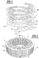
- a properly controlled annealing is provided to the lamination core having a helical lamination strip 18 after welding, as shown in Fig. 9 , to relieve the stress and strain in the electrical steel material of the back-iron 19 and the projecting teeth 20 subjected to elastic strain and recrystallization at areas of plastic deformation caused by bending forces applied to the strip during helical winding.
- Indentations 21 are provided with a respective weld 22 before the annealing.
- the teeth may be straight as shown at 60 and have a slight concavity at the stamped edge facing the rotor.
- an important feature of this preferred exemplary embodiment is the application of controlled annealing to helical wound alternator cores.
- the result is a significant improvement in electrical properties of the steel, including core loss, which results in an increase in current output and increase in efficiency.
- This may be shown by the following plots of core loss vs. induction ( Fig. 11 ) and induced field (B) vs. applied field (H) ( Fig. 12 ) for both a core made using a regular prior art production process and a core that has been annealed under controlled atmosphere and temperature conditions according to a preferred exemplary embodiment.
- the plot of core loss vs. induction shows reduced losses for the annealed core at the same flux level (Induction).
- FIG. 12 The plot of induced field (B) vs. applied field (H) ( Fig. 12 ) shows that the annealed core carries a much higher flux or induced field (B) for a fixed level of applied field.
- the direct result or interpretation is that, for a fixed applied voltage in a stator or core winding the annealed core will provide a higher excitation current and consequently a higher efficiency.
- Figure 11 shows the comparison of Core loss vs. Induction for helical wound alternator cores using a regular or normal (prior art) production method and cores that have been annealed according to a preferred exemplary embodiment.
- Figure 12 shows the comparison or induced field (B) vs. applied field (H) for helical wound alternator cores using the regular or normal (prior art) production method and cores that have been annealed.
- B induced field
- H applied field
- the conditions for annealing of helically wound alternator cores are carefully defined and are similar to conditions for annealing of stacked, separate loose stator and rotor laminations and interlocked stacks, all using progressively stamped separate and stacked laminations.
- a lamination strip having a thickness in a range from 0.35 mm to 1.00 mm, and preferably having a thickness of approximately 0.05 mm, and having a back-iron and projecting teeth for an alternator core to be helically wound is created by stamping.
- the stamped strip is helically wound by bending to form a helically wound alternator core.
- the core is welded at peripherally spaced locations as in the prior art and also the space between adjacent teeth is coined.
- the helically wound core is annealed in a neutral or decarburizing atmosphere at temperatures above 399°C (750°F). More particularly, the basic conditions for the annealing of the helically wound alternator cores include:
Landscapes
- Engineering & Computer Science (AREA)
- Manufacturing & Machinery (AREA)
- Power Engineering (AREA)
- Iron Core Of Rotating Electric Machines (AREA)
- Manufacture Of Motors, Generators (AREA)
- Heat Treatment Of Articles (AREA)
- Manufacturing Cores, Coils, And Magnets (AREA)
Applications Claiming Priority (1)
| Application Number | Priority Date | Filing Date | Title |
|---|---|---|---|
| US13/793,565 US9214845B2 (en) | 2013-03-11 | 2013-03-11 | Process for annealing of helical wound cores used for automotive alternator applications |
Publications (3)
| Publication Number | Publication Date |
|---|---|
| EP2779381A2 EP2779381A2 (en) | 2014-09-17 |
| EP2779381A3 EP2779381A3 (en) | 2016-04-13 |
| EP2779381B1 true EP2779381B1 (en) | 2017-12-13 |
Family
ID=48128087
Family Applications (1)
| Application Number | Title | Priority Date | Filing Date |
|---|---|---|---|
| EP13162496.7A Not-in-force EP2779381B1 (en) | 2013-03-11 | 2013-04-05 | Process for annealing of helical wound cores used for automotive alternator applications |
Country Status (5)
| Country | Link |
|---|---|
| US (1) | US9214845B2 (https=) |
| EP (1) | EP2779381B1 (https=) |
| JP (1) | JP2014175649A (https=) |
| CA (1) | CA2811540C (https=) |
| MX (1) | MX2013004236A (https=) |
Families Citing this family (5)
| Publication number | Priority date | Publication date | Assignee | Title |
|---|---|---|---|---|
| US10199910B2 (en) * | 2014-10-03 | 2019-02-05 | Ford Global Technologies, Llc | Motor core formed from a single steel source and having separately processed rotor and stator laminations |
| US10879777B2 (en) | 2017-12-11 | 2020-12-29 | Ford Global Technologies, Llc | Rapid stress relief annealing of a stator |
| CN111722152B (zh) * | 2020-06-29 | 2023-04-28 | 成都工百利自动化设备有限公司 | 一种变压器绕组变形监测方法及监测系统 |
| EP3937348A1 (de) * | 2020-07-09 | 2022-01-12 | Siemens Aktiengesellschaft | Blechpaketsegment und verfahren zu dessen herstellung |
| WO2022194390A1 (en) * | 2021-03-19 | 2022-09-22 | Che-Motor Ag | Rotating electromechanical apparatus and method of manufacture of stator winding |
Family Cites Families (35)
| Publication number | Priority date | Publication date | Assignee | Title |
|---|---|---|---|---|
| US2348003A (en) | 1941-01-28 | 1944-05-02 | Gen Electric | Magnetic core |
| US3283399A (en) * | 1964-03-11 | 1966-11-08 | Gen Electric | Method of forming electromagnetic cores |
| US4779812A (en) | 1982-01-06 | 1988-10-25 | Kuhlman Corporation | Toroidal electrical transformer and method of producing same |
| JPH0241641A (ja) * | 1988-07-28 | 1990-02-09 | Hitachi Ltd | 電動機用固定子の製造方法 |
| JPH0295147A (ja) * | 1988-09-28 | 1990-04-05 | Hitachi Ltd | 電動機用固定子巻き鉄心の製造方法 |
| US5225005A (en) | 1991-03-28 | 1993-07-06 | Cooper Power Systems, Inc. | Method of annealing/magnetic annealing of amorphous metal in a fluidized bed and apparatus therefor |
| US5542995A (en) * | 1992-02-19 | 1996-08-06 | Reilly; Robert | Method of making steel strapping and strip and strapping and strip |
| AU4987193A (en) | 1992-09-14 | 1994-04-12 | Cadac Holdings Limited | Dynamoelectric machine and stators therefor |
| EP0684320B1 (en) | 1994-04-26 | 2000-06-21 | LTV STEEL COMPANY, Inc. | Process of making electrical steels |
| JPH07298570A (ja) * | 1994-04-28 | 1995-11-10 | Nippon Steel Corp | 螺旋コアの製造方法 |
| US5982073A (en) | 1997-12-16 | 1999-11-09 | Materials Innovation, Inc. | Low core loss, well-bonded soft magnetic parts |
| IL126748A0 (en) | 1998-10-26 | 1999-08-17 | Amt Ltd | Three-phase transformer and method for manufacturing same |
| JP2001275283A (ja) | 2000-03-28 | 2001-10-05 | Mitsubishi Electric Corp | 車両用交流発電機の固定子 |
| JP3593009B2 (ja) | 2000-07-27 | 2004-11-24 | 三菱電機株式会社 | 回転電機 |
| EP1441044B1 (en) | 2001-10-05 | 2017-11-29 | Nippon Steel & Sumitomo Metal Corporation | Iron core exhibiting excellent insulating property at end face |
| US6879080B2 (en) | 2002-01-30 | 2005-04-12 | Ramon A. Caamano | High frequency electric motor or generator including magnetic cores formed from thin film soft magnetic material |
| US7144468B2 (en) | 2002-09-05 | 2006-12-05 | Metglas, Inc. | Method of constructing a unitary amorphous metal component for an electric machine |
| US7235910B2 (en) | 2003-04-25 | 2007-06-26 | Metglas, Inc. | Selective etching process for cutting amorphous metal shapes and components made thereof |
| US7596856B2 (en) | 2003-06-11 | 2009-10-06 | Light Engineering, Inc. | Method for manufacturing a soft magnetic metal electromagnetic component |
| US20080246362A1 (en) | 2003-06-12 | 2008-10-09 | Hirzel Andrew D | Radial airgap, transverse flux machine |
| EP1649574A2 (en) | 2003-07-10 | 2006-04-26 | Magnetic Applications Inc. | Compact high power alternator |
| JP4569104B2 (ja) * | 2003-12-25 | 2010-10-27 | Jfeスチール株式会社 | 磁気特性に優れたヘリカル加工用コア材料及びその製造方法、並びにヘリカル加工ステーターコア |
| DE102006044436C5 (de) | 2006-09-21 | 2020-07-30 | Robert Bosch Gmbh | Vorrichtung zur Energiespeicherung und Energietransformierung |
| JP2008245471A (ja) | 2007-03-28 | 2008-10-09 | Mitsubishi Electric Corp | 回転電機 |
| EP1975269A1 (fr) | 2007-03-30 | 2008-10-01 | Imphy Alloys | Alliage austenitique fer-nickel-chrome-cuivre |
| US7603760B1 (en) | 2007-07-12 | 2009-10-20 | Tempel Steel Company | Method for producing a helical stator |
| US7847466B2 (en) | 2007-09-04 | 2010-12-07 | Mitsui High-Tec, Inc. | Laminated core and method for manufacturing the same |
| EP2224461B1 (en) | 2009-02-25 | 2011-11-30 | Liaisons Electroniques-Mecaniques Lem S.A. | Magnetic circuit with wound magnetic core |
| CN102376425A (zh) | 2010-08-25 | 2012-03-14 | 天津市新阳电子有限公司 | 设置气隙磁钢片的插接式汽车点火线圈铁芯 |
| CN103329408B (zh) * | 2011-01-28 | 2015-11-25 | 新日铁住金株式会社 | 旋转电机用螺旋铁心的制造方法及旋转电机用螺旋铁心的制造装置 |
| JP5621626B2 (ja) * | 2011-01-28 | 2014-11-12 | 新日鐵住金株式会社 | 回転電機用螺旋コアの製造方法および回転電機用螺旋コアの製造装置 |
| JP5382033B2 (ja) * | 2011-03-01 | 2014-01-08 | 株式会社デンソー | 回転電機の固定子鉄心の製造方法および回転電機の固定子鉄心 |
| JP5327257B2 (ja) | 2011-03-30 | 2013-10-30 | 日立金属株式会社 | 巻鉄心、電磁部品とその製造方法および電磁機器 |
| JP2012217279A (ja) * | 2011-04-01 | 2012-11-08 | Toyota Motor Corp | 回転電機用ステータコア、回転電機、および、回転電機用ステータコアの製造方法 |
| US20130033146A1 (en) | 2011-08-04 | 2013-02-07 | Mark Bender | Segmented rotor and stator lamination cores |
-
2013
- 2013-03-11 US US13/793,565 patent/US9214845B2/en not_active Expired - Fee Related
- 2013-04-02 CA CA2811540A patent/CA2811540C/en not_active Expired - Fee Related
- 2013-04-05 EP EP13162496.7A patent/EP2779381B1/en not_active Not-in-force
- 2013-04-16 MX MX2013004236A patent/MX2013004236A/es active IP Right Grant
- 2013-04-25 JP JP2013092431A patent/JP2014175649A/ja active Pending
Non-Patent Citations (1)
| Title |
|---|
| None * |
Also Published As
| Publication number | Publication date |
|---|---|
| EP2779381A2 (en) | 2014-09-17 |
| JP2014175649A (ja) | 2014-09-22 |
| CA2811540C (en) | 2020-03-10 |
| US20140250681A1 (en) | 2014-09-11 |
| MX2013004236A (es) | 2014-09-16 |
| EP2779381A3 (en) | 2016-04-13 |
| CA2811540A1 (en) | 2014-09-11 |
| US9214845B2 (en) | 2015-12-15 |
Similar Documents
| Publication | Publication Date | Title |
|---|---|---|
| US9647517B2 (en) | Manufacturing method for helical core for rotating electrical machine and manufacturing device for helical core for rotating electrical machine | |
| EP2779381B1 (en) | Process for annealing of helical wound cores used for automotive alternator applications | |
| CN101682219B (zh) | 叠层铁芯及其制造方法 | |
| US20160254718A1 (en) | Segment conductors, stator, rotating electrical machine, and vehicle and method of manufacturing the segment conductors | |
| KR100636490B1 (ko) | 회전 전기 기계의 고정자 및 그 고정자 코일의 제조 방법 | |
| US6742238B2 (en) | Flare tooth stator for an AC generator | |
| JP2011151884A (ja) | 回転電機および回転電機の固定子の製造方法 | |
| JP2007181303A (ja) | モータ | |
| JP2007159300A (ja) | 回転電機の固定子 | |
| JP4781197B2 (ja) | 分割積層鉄心及びこの分割積層鉄心を用いた回転電機の固定子鉄心 | |
| CN104937814B (zh) | 电机和用于制造电气叠片的方法 | |
| US20040187293A1 (en) | Radial insertion of stator hairpin windings | |
| JP7254526B2 (ja) | 電磁鋼板積層体およびその製造方法 | |
| JP2021175240A (ja) | 鉄心の製造方法、鉄心、および固定子 | |
| CN103326519B (zh) | 用于制造交流发电机螺旋盘绕铁芯的工艺 | |
| US20050046299A1 (en) | Windings for electric machines | |
| WO2019082679A1 (ja) | 回転電機、回転電機の製造方法、固定子 | |
| JP2021097499A (ja) | 回転電機のステータ | |
| CN113922528B (zh) | 电机的定子组件及制造方法 | |
| CN102077448A (zh) | 用于电机的定子铁芯 | |
| JP6727458B2 (ja) | 固定子鉄心及びその固定子鉄心を備えた電動機 | |
| JP2022110252A (ja) | 電機子の製造方法、電機子、及び鉄心 | |
| JP2003259610A (ja) | 積層鉄心の製造方法および製造装置 | |
| JP5649545B2 (ja) | 回転電機の製造方法 | |
| JP7371506B2 (ja) | 電機子の製造方法及び電機子 |
Legal Events
| Date | Code | Title | Description |
|---|---|---|---|
| PUAI | Public reference made under article 153(3) epc to a published international application that has entered the european phase |
Free format text: ORIGINAL CODE: 0009012 |
|
| 17P | Request for examination filed |
Effective date: 20130405 |
|
| AK | Designated contracting states |
Kind code of ref document: A2 Designated state(s): AL AT BE BG CH CY CZ DE DK EE ES FI FR GB GR HR HU IE IS IT LI LT LU LV MC MK MT NL NO PL PT RO RS SE SI SK SM TR |
|
| AX | Request for extension of the european patent |
Extension state: BA ME |
|
| PUAL | Search report despatched |
Free format text: ORIGINAL CODE: 0009013 |
|
| AK | Designated contracting states |
Kind code of ref document: A3 Designated state(s): AL AT BE BG CH CY CZ DE DK EE ES FI FR GB GR HR HU IE IS IT LI LT LU LV MC MK MT NL NO PL PT RO RS SE SI SK SM TR |
|
| AX | Request for extension of the european patent |
Extension state: BA ME |
|
| RIC1 | Information provided on ipc code assigned before grant |
Ipc: H02K 15/02 20060101AFI20160304BHEP |
|
| R17P | Request for examination filed (corrected) |
Effective date: 20161011 |
|
| RBV | Designated contracting states (corrected) |
Designated state(s): AL AT BE BG CH CY CZ DE DK EE ES FI FR GB GR HR HU IE IS IT LI LT LU LV MC MK MT NL NO PL PT RO RS SE SI SK SM TR |
|
| GRAP | Despatch of communication of intention to grant a patent |
Free format text: ORIGINAL CODE: EPIDOSNIGR1 |
|
| STAA | Information on the status of an ep patent application or granted ep patent |
Free format text: STATUS: GRANT OF PATENT IS INTENDED |
|
| INTG | Intention to grant announced |
Effective date: 20170706 |
|
| GRAS | Grant fee paid |
Free format text: ORIGINAL CODE: EPIDOSNIGR3 |
|
| GRAA | (expected) grant |
Free format text: ORIGINAL CODE: 0009210 |
|
| STAA | Information on the status of an ep patent application or granted ep patent |
Free format text: STATUS: THE PATENT HAS BEEN GRANTED |
|
| AK | Designated contracting states |
Kind code of ref document: B1 Designated state(s): AL AT BE BG CH CY CZ DE DK EE ES FI FR GB GR HR HU IE IS IT LI LT LU LV MC MK MT NL NO PL PT RO RS SE SI SK SM TR |
|
| REG | Reference to a national code |
Ref country code: GB Ref legal event code: FG4D |
|
| REG | Reference to a national code |
Ref country code: AT Ref legal event code: REF Ref document number: 955249 Country of ref document: AT Kind code of ref document: T Effective date: 20171215 Ref country code: CH Ref legal event code: EP |
|
| REG | Reference to a national code |
Ref country code: IE Ref legal event code: FG4D |
|
| REG | Reference to a national code |
Ref country code: DE Ref legal event code: R096 Ref document number: 602013030670 Country of ref document: DE |
|
| REG | Reference to a national code |
Ref country code: FR Ref legal event code: PLFP Year of fee payment: 6 |
|
| REG | Reference to a national code |
Ref country code: NL Ref legal event code: MP Effective date: 20171213 |
|
| REG | Reference to a national code |
Ref country code: LT Ref legal event code: MG4D |
|
| PG25 | Lapsed in a contracting state [announced via postgrant information from national office to epo] |
Ref country code: FI Free format text: LAPSE BECAUSE OF FAILURE TO SUBMIT A TRANSLATION OF THE DESCRIPTION OR TO PAY THE FEE WITHIN THE PRESCRIBED TIME-LIMIT Effective date: 20171213 Ref country code: NO Free format text: LAPSE BECAUSE OF FAILURE TO SUBMIT A TRANSLATION OF THE DESCRIPTION OR TO PAY THE FEE WITHIN THE PRESCRIBED TIME-LIMIT Effective date: 20180313 Ref country code: SE Free format text: LAPSE BECAUSE OF FAILURE TO SUBMIT A TRANSLATION OF THE DESCRIPTION OR TO PAY THE FEE WITHIN THE PRESCRIBED TIME-LIMIT Effective date: 20171213 Ref country code: LT Free format text: LAPSE BECAUSE OF FAILURE TO SUBMIT A TRANSLATION OF THE DESCRIPTION OR TO PAY THE FEE WITHIN THE PRESCRIBED TIME-LIMIT Effective date: 20171213 |
|
| REG | Reference to a national code |
Ref country code: AT Ref legal event code: MK05 Ref document number: 955249 Country of ref document: AT Kind code of ref document: T Effective date: 20171213 |
|
| PG25 | Lapsed in a contracting state [announced via postgrant information from national office to epo] |
Ref country code: HR Free format text: LAPSE BECAUSE OF FAILURE TO SUBMIT A TRANSLATION OF THE DESCRIPTION OR TO PAY THE FEE WITHIN THE PRESCRIBED TIME-LIMIT Effective date: 20171213 Ref country code: RS Free format text: LAPSE BECAUSE OF FAILURE TO SUBMIT A TRANSLATION OF THE DESCRIPTION OR TO PAY THE FEE WITHIN THE PRESCRIBED TIME-LIMIT Effective date: 20171213 Ref country code: BG Free format text: LAPSE BECAUSE OF FAILURE TO SUBMIT A TRANSLATION OF THE DESCRIPTION OR TO PAY THE FEE WITHIN THE PRESCRIBED TIME-LIMIT Effective date: 20180313 Ref country code: LV Free format text: LAPSE BECAUSE OF FAILURE TO SUBMIT A TRANSLATION OF THE DESCRIPTION OR TO PAY THE FEE WITHIN THE PRESCRIBED TIME-LIMIT Effective date: 20171213 Ref country code: GR Free format text: LAPSE BECAUSE OF FAILURE TO SUBMIT A TRANSLATION OF THE DESCRIPTION OR TO PAY THE FEE WITHIN THE PRESCRIBED TIME-LIMIT Effective date: 20180314 |
|
| PG25 | Lapsed in a contracting state [announced via postgrant information from national office to epo] |
Ref country code: NL Free format text: LAPSE BECAUSE OF FAILURE TO SUBMIT A TRANSLATION OF THE DESCRIPTION OR TO PAY THE FEE WITHIN THE PRESCRIBED TIME-LIMIT Effective date: 20171213 |
|
| PG25 | Lapsed in a contracting state [announced via postgrant information from national office to epo] |
Ref country code: ES Free format text: LAPSE BECAUSE OF FAILURE TO SUBMIT A TRANSLATION OF THE DESCRIPTION OR TO PAY THE FEE WITHIN THE PRESCRIBED TIME-LIMIT Effective date: 20171213 Ref country code: SK Free format text: LAPSE BECAUSE OF FAILURE TO SUBMIT A TRANSLATION OF THE DESCRIPTION OR TO PAY THE FEE WITHIN THE PRESCRIBED TIME-LIMIT Effective date: 20171213 Ref country code: EE Free format text: LAPSE BECAUSE OF FAILURE TO SUBMIT A TRANSLATION OF THE DESCRIPTION OR TO PAY THE FEE WITHIN THE PRESCRIBED TIME-LIMIT Effective date: 20171213 Ref country code: CY Free format text: LAPSE BECAUSE OF FAILURE TO SUBMIT A TRANSLATION OF THE DESCRIPTION OR TO PAY THE FEE WITHIN THE PRESCRIBED TIME-LIMIT Effective date: 20171213 Ref country code: CZ Free format text: LAPSE BECAUSE OF FAILURE TO SUBMIT A TRANSLATION OF THE DESCRIPTION OR TO PAY THE FEE WITHIN THE PRESCRIBED TIME-LIMIT Effective date: 20171213 |
|
| PG25 | Lapsed in a contracting state [announced via postgrant information from national office to epo] |
Ref country code: AT Free format text: LAPSE BECAUSE OF FAILURE TO SUBMIT A TRANSLATION OF THE DESCRIPTION OR TO PAY THE FEE WITHIN THE PRESCRIBED TIME-LIMIT Effective date: 20171213 Ref country code: SM Free format text: LAPSE BECAUSE OF FAILURE TO SUBMIT A TRANSLATION OF THE DESCRIPTION OR TO PAY THE FEE WITHIN THE PRESCRIBED TIME-LIMIT Effective date: 20171213 Ref country code: PL Free format text: LAPSE BECAUSE OF FAILURE TO SUBMIT A TRANSLATION OF THE DESCRIPTION OR TO PAY THE FEE WITHIN THE PRESCRIBED TIME-LIMIT Effective date: 20171213 Ref country code: RO Free format text: LAPSE BECAUSE OF FAILURE TO SUBMIT A TRANSLATION OF THE DESCRIPTION OR TO PAY THE FEE WITHIN THE PRESCRIBED TIME-LIMIT Effective date: 20171213 Ref country code: IS Free format text: LAPSE BECAUSE OF FAILURE TO SUBMIT A TRANSLATION OF THE DESCRIPTION OR TO PAY THE FEE WITHIN THE PRESCRIBED TIME-LIMIT Effective date: 20180413 |
|
| REG | Reference to a national code |
Ref country code: DE Ref legal event code: R097 Ref document number: 602013030670 Country of ref document: DE |
|
| PLBE | No opposition filed within time limit |
Free format text: ORIGINAL CODE: 0009261 |
|
| STAA | Information on the status of an ep patent application or granted ep patent |
Free format text: STATUS: NO OPPOSITION FILED WITHIN TIME LIMIT |
|
| 26N | No opposition filed |
Effective date: 20180914 |
|
| PG25 | Lapsed in a contracting state [announced via postgrant information from national office to epo] |
Ref country code: MC Free format text: LAPSE BECAUSE OF FAILURE TO SUBMIT A TRANSLATION OF THE DESCRIPTION OR TO PAY THE FEE WITHIN THE PRESCRIBED TIME-LIMIT Effective date: 20171213 Ref country code: DK Free format text: LAPSE BECAUSE OF FAILURE TO SUBMIT A TRANSLATION OF THE DESCRIPTION OR TO PAY THE FEE WITHIN THE PRESCRIBED TIME-LIMIT Effective date: 20171213 |
|
| REG | Reference to a national code |
Ref country code: CH Ref legal event code: PL |
|
| REG | Reference to a national code |
Ref country code: BE Ref legal event code: MM Effective date: 20180430 |
|
| GBPC | Gb: european patent ceased through non-payment of renewal fee |
Effective date: 20180405 |
|
| REG | Reference to a national code |
Ref country code: IE Ref legal event code: MM4A |
|
| PG25 | Lapsed in a contracting state [announced via postgrant information from national office to epo] |
Ref country code: LU Free format text: LAPSE BECAUSE OF NON-PAYMENT OF DUE FEES Effective date: 20180405 |
|
| PG25 | Lapsed in a contracting state [announced via postgrant information from national office to epo] |
Ref country code: BE Free format text: LAPSE BECAUSE OF NON-PAYMENT OF DUE FEES Effective date: 20180430 Ref country code: SI Free format text: LAPSE BECAUSE OF FAILURE TO SUBMIT A TRANSLATION OF THE DESCRIPTION OR TO PAY THE FEE WITHIN THE PRESCRIBED TIME-LIMIT Effective date: 20171213 Ref country code: LI Free format text: LAPSE BECAUSE OF NON-PAYMENT OF DUE FEES Effective date: 20180430 Ref country code: GB Free format text: LAPSE BECAUSE OF NON-PAYMENT OF DUE FEES Effective date: 20180405 Ref country code: CH Free format text: LAPSE BECAUSE OF NON-PAYMENT OF DUE FEES Effective date: 20180430 |
|
| PG25 | Lapsed in a contracting state [announced via postgrant information from national office to epo] |
Ref country code: IE Free format text: LAPSE BECAUSE OF NON-PAYMENT OF DUE FEES Effective date: 20180405 |
|
| PGFP | Annual fee paid to national office [announced via postgrant information from national office to epo] |
Ref country code: FR Payment date: 20190313 Year of fee payment: 7 |
|
| PGFP | Annual fee paid to national office [announced via postgrant information from national office to epo] |
Ref country code: IT Payment date: 20190419 Year of fee payment: 7 Ref country code: DE Payment date: 20190326 Year of fee payment: 7 |
|
| PG25 | Lapsed in a contracting state [announced via postgrant information from national office to epo] |
Ref country code: MT Free format text: LAPSE BECAUSE OF NON-PAYMENT OF DUE FEES Effective date: 20180405 |
|
| PG25 | Lapsed in a contracting state [announced via postgrant information from national office to epo] |
Ref country code: TR Free format text: LAPSE BECAUSE OF FAILURE TO SUBMIT A TRANSLATION OF THE DESCRIPTION OR TO PAY THE FEE WITHIN THE PRESCRIBED TIME-LIMIT Effective date: 20171213 |
|
| PG25 | Lapsed in a contracting state [announced via postgrant information from national office to epo] |
Ref country code: PT Free format text: LAPSE BECAUSE OF FAILURE TO SUBMIT A TRANSLATION OF THE DESCRIPTION OR TO PAY THE FEE WITHIN THE PRESCRIBED TIME-LIMIT Effective date: 20171213 Ref country code: HU Free format text: LAPSE BECAUSE OF FAILURE TO SUBMIT A TRANSLATION OF THE DESCRIPTION OR TO PAY THE FEE WITHIN THE PRESCRIBED TIME-LIMIT; INVALID AB INITIO Effective date: 20130405 |
|
| PG25 | Lapsed in a contracting state [announced via postgrant information from national office to epo] |
Ref country code: MK Free format text: LAPSE BECAUSE OF NON-PAYMENT OF DUE FEES Effective date: 20171213 |
|
| PG25 | Lapsed in a contracting state [announced via postgrant information from national office to epo] |
Ref country code: AL Free format text: LAPSE BECAUSE OF FAILURE TO SUBMIT A TRANSLATION OF THE DESCRIPTION OR TO PAY THE FEE WITHIN THE PRESCRIBED TIME-LIMIT Effective date: 20171213 |
|
| REG | Reference to a national code |
Ref country code: DE Ref legal event code: R119 Ref document number: 602013030670 Country of ref document: DE |
|
| PG25 | Lapsed in a contracting state [announced via postgrant information from national office to epo] |
Ref country code: DE Free format text: LAPSE BECAUSE OF NON-PAYMENT OF DUE FEES Effective date: 20201103 Ref country code: FR Free format text: LAPSE BECAUSE OF NON-PAYMENT OF DUE FEES Effective date: 20200430 |
|
| PG25 | Lapsed in a contracting state [announced via postgrant information from national office to epo] |
Ref country code: IT Free format text: LAPSE BECAUSE OF NON-PAYMENT OF DUE FEES Effective date: 20200405 |