EP2779381B1 - Process for annealing of helical wound cores used for automotive alternator applications - Google Patents
Process for annealing of helical wound cores used for automotive alternator applications Download PDFInfo
- Publication number
- EP2779381B1 EP2779381B1 EP13162496.7A EP13162496A EP2779381B1 EP 2779381 B1 EP2779381 B1 EP 2779381B1 EP 13162496 A EP13162496 A EP 13162496A EP 2779381 B1 EP2779381 B1 EP 2779381B1
- Authority
- EP
- European Patent Office
- Prior art keywords
- core
- iron
- annealing
- strip
- helically wound
- Prior art date
- Legal status (The legal status is an assumption and is not a legal conclusion. Google has not performed a legal analysis and makes no representation as to the accuracy of the status listed.)
- Not-in-force
Links
Images


Classifications
-
- H—ELECTRICITY
- H02—GENERATION; CONVERSION OR DISTRIBUTION OF ELECTRIC POWER
- H02K—DYNAMO-ELECTRIC MACHINES
- H02K15/00—Methods or apparatus specially adapted for manufacturing, assembling, maintaining or repairing of dynamo-electric machines
- H02K15/02—Methods or apparatus specially adapted for manufacturing, assembling, maintaining or repairing of dynamo-electric machines of stator or rotor bodies
- H02K15/024—Methods or apparatus specially adapted for manufacturing, assembling, maintaining or repairing of dynamo-electric machines of stator or rotor bodies with slots
- H02K15/026—Wound cores
-
- Y—GENERAL TAGGING OF NEW TECHNOLOGICAL DEVELOPMENTS; GENERAL TAGGING OF CROSS-SECTIONAL TECHNOLOGIES SPANNING OVER SEVERAL SECTIONS OF THE IPC; TECHNICAL SUBJECTS COVERED BY FORMER USPC CROSS-REFERENCE ART COLLECTIONS [XRACs] AND DIGESTS
- Y10—TECHNICAL SUBJECTS COVERED BY FORMER USPC
- Y10T—TECHNICAL SUBJECTS COVERED BY FORMER US CLASSIFICATION
- Y10T29/00—Metal working
- Y10T29/49—Method of mechanical manufacture
- Y10T29/49002—Electrical device making
- Y10T29/4902—Electromagnet, transformer or inductor
Definitions
- a normal approach taken by automotive manufacturers and Tier 1 suppliers for an increase in current output and efficiency is to increase the diameter and/or the core height of the helical wound core.
- Another option is to increase the number of slots in the helical wound core which allows a more efficient design of copper winding to be inserted.
- weight can be added by increasing the mass of the alternator core.
- slots can be added to a core since there needs to be a balance between wire diameter, number of turns and the amount of steel used in the teeth of the core to establish sufficient electrical flux. So both of these design options appear, to those skilled in this art, to have reached limits, which do not seem to those skilled in this art to readily provide further options for increased current output.
- FIG. 5A a first prior art method for helically winding a strip 12 is illustrated.
- An inside pressure wheel 8 is provided which contacts an outer edge 12G of the teeth 12B and exerts a force thereon.
- an outer pressure wheel 7 is provided which abuts against an outer edge 12F of the back-iron 12A of the strip 12. The strip is thus bent, resulting in internal plastic deformation in both the teeth 12B and within the back-iron 12A of strip 12.
- Inside pressure wheel 8 may also be a mandrel or have an associated mandrel about which the strip is helically wound.
- FIG. 5B A second prior art method is shown in Fig. 5B which is known from U.S. Patent 7,797,977 .
- an outside pressure wheel 4 is provided along with a partial cone-shaped inside pressure wheel 5 having notches 5A.
- the notches 5A receive a base portion of the teeth 12B.
- a separate mandrel 6 is also provided to receive the helically bent strip.
- the teeth 12B are not stressed by the bending (but are stressed by stamping) and plastic deformation still occurs in the back-iron 12A which is subjected to bending pressure by the inside pressure wheel 5 on the inner edge 12E of the back-iron 12A and pressure is also applied by the outside pressure wheel 4 on the outside edge 12F of the back-iron 12A.
- plastic deformation occurs within the back-iron.
- WO 2012/101812 A describes a method for manufacturing a helically wound alternator core, comprising the steps of: stamping an electrical steel strip to create a lamination strip having a back-iron and projecting teeth; helically winding the lamination strip by applying at least one force to the strip to bend the lamination strip to form the helically wound alternator core, said at least one force causing plastic deformation resulting in internal stress and strain in at least said back-iron of the strip; welding the helically wound alternator core; and thereafter, annealing the welded helically wound alternator core.
- US 2013/276297 A1 and JP 2012 217279 A describe a manufacturing method of a helical core and describe T-shaped projecting teeth.
- a method for manufacturing a helically wound alternator core an electrical steel strip is stamped to create a lamination strip having a back-iron and projecting teeth.
- the lamination strip is helically wound by bending the lamination strip to form the helically wound alternator core.
- the core is then welded. Thereafter the welded helically wound alternator core is annealed, or coined and then annealed.
- Figure 6 shows an illustration of a typical stamped stator tooth 12B extending from a back-iron 12A. If this tooth 12B is cross-sectioned through line AA using standard metallographic techniques, it is possible to make microhardness measurements in progressive steps from the stamped (or possibly compressed) edge 12G of the tooth into the middle of the tooth.
- Figure 6 is thus a schematic of a typical stamped stator tooth illustrating the location of cross-section AA for Figure7 .
- Figure 7 shows the cross-section through the tooth 12B at a magnification of 50 x.
- Figure 7 clearly shows the rolled edge 50 (resulting from the punch entry), the shear section 51 from the punch, the tensile break section 52, and the small burr 53 at the bottom as the punch exits the material.
- Figure 7 also shows lines of black dots 54, each of which represents a micro-hardness reading shown in Fig. 8 .
- Figure 7 is a cross-section photomicrograph at 50 x magnification, of a typical stamped tooth 12B with the stamped edge 12G on the left.
- the black dots 54 are the locations for each micro-hardness reading.
- the table of Fig. 8 shows the results for one line of micro-hardness readings.
- the data shows that, at a distance of 0.0381 mm (0.0015") from the stamped edge 12G, the hardness reading is 232 HV (Vickers Hardness scale), and this reduces to 202 HV at 0.0762 mm (0.0030") from the stamped edge, and continues to decrease until a distance of 0.635 mm (0.025") from the stamped edge is reached, where the hardness is 98 HV.
- HV Vickers Hardness scale
- the width WT of the stator teeth ( Fig. 2 ) and width WB of the back-iron 12A are relatively small for a helical wound alternator core.
- the ratio of plastically deformed steel compared to the total volume of steel is very high in a prior art helical wound alternator core.
- flux is concentrated at the edges and surfaces of electrical cores (called the "skin effect"), and that the depth of the skin effect reduces as frequency is increased. This means that any plastic deformation on the edges and surface, especially in a helical wound core where the ratio of plastically deformed steel compared to the total volume of steel is very high, will result in a significant degradation of electrical properties for the steel.
- a properly controlled annealing is provided to the lamination core having a helical lamination strip 18 after welding, as shown in Fig. 9 , to relieve the stress and strain in the electrical steel material of the back-iron 19 and the projecting teeth 20 subjected to elastic strain and recrystallization at areas of plastic deformation caused by bending forces applied to the strip during helical winding.
- Indentations 21 are provided with a respective weld 22 before the annealing.
- the teeth may be straight as shown at 60 and have a slight concavity at the stamped edge facing the rotor.
- an important feature of this preferred exemplary embodiment is the application of controlled annealing to helical wound alternator cores.
- the result is a significant improvement in electrical properties of the steel, including core loss, which results in an increase in current output and increase in efficiency.
- This may be shown by the following plots of core loss vs. induction ( Fig. 11 ) and induced field (B) vs. applied field (H) ( Fig. 12 ) for both a core made using a regular prior art production process and a core that has been annealed under controlled atmosphere and temperature conditions according to a preferred exemplary embodiment.
- the plot of core loss vs. induction shows reduced losses for the annealed core at the same flux level (Induction).
- FIG. 12 The plot of induced field (B) vs. applied field (H) ( Fig. 12 ) shows that the annealed core carries a much higher flux or induced field (B) for a fixed level of applied field.
- the direct result or interpretation is that, for a fixed applied voltage in a stator or core winding the annealed core will provide a higher excitation current and consequently a higher efficiency.
- Figure 11 shows the comparison of Core loss vs. Induction for helical wound alternator cores using a regular or normal (prior art) production method and cores that have been annealed according to a preferred exemplary embodiment.
- Figure 12 shows the comparison or induced field (B) vs. applied field (H) for helical wound alternator cores using the regular or normal (prior art) production method and cores that have been annealed.
- B induced field
- H applied field
- the conditions for annealing of helically wound alternator cores are carefully defined and are similar to conditions for annealing of stacked, separate loose stator and rotor laminations and interlocked stacks, all using progressively stamped separate and stacked laminations.
- a lamination strip having a thickness in a range from 0.35 mm to 1.00 mm, and preferably having a thickness of approximately 0.05 mm, and having a back-iron and projecting teeth for an alternator core to be helically wound is created by stamping.
- the stamped strip is helically wound by bending to form a helically wound alternator core.
- the core is welded at peripherally spaced locations as in the prior art and also the space between adjacent teeth is coined.
- the helically wound core is annealed in a neutral or decarburizing atmosphere at temperatures above 399°C (750°F). More particularly, the basic conditions for the annealing of the helically wound alternator cores include:
Landscapes
- Engineering & Computer Science (AREA)
- Manufacturing & Machinery (AREA)
- Power Engineering (AREA)
- Iron Core Of Rotating Electric Machines (AREA)
- Manufacture Of Motors, Generators (AREA)
- Heat Treatment Of Articles (AREA)
- Manufacturing Cores, Coils, And Magnets (AREA)
Description
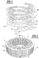
- A majority of steel stator cores used for production of automotive alternators, such as shown in
Figs. 1 and4 at 10 are produced using a well-established process called helical winding (albeit with some variations) such as shown at 11 inFig. 3 , that involves the following basic steps: - 1) Slitting a thin width coil, typically 20 mm to 70 mm in width, from a wide coil of electrical steel where the thickness is typically 0.50 mm but which may vary from 0.35 to 1.00 mm.
- 2) Stamping with a
stamping die 2 theslit coil 1 as shown inFig. 2 to create two separatecontinuous strips straight support section 12A (called the "back-iron") from which protrudeteeth 12B which may be straight or look like "T" sections attached to the back-iron. Theteeth end faces 12G have a slight concavity or curvature substantially matching a rotor peripheral curvature.Gaps 12C between the teeth are known as "slots" (seeFigs. 2 and3 ).Indentations 3 are provided opposite the base of each tooth in the back-iron. - 3) Winding each of the continuous strips, such as onto a central mandrel, such that each strip forms a helix 11 (with turns separated as shown in
Fig. 3 ) which forms the helical core 10 (Figs. 1 and4 ), similar in concept to a child's toy popularly known as a "Slinky". After winding to a fixed core height (or mass), the continuous strip is cut, leaving an individualhelical core 10. - 4) Clamping and welding at for example separated locations 9 (
Figs. 1 and4 ) around a periphery of the helical wound core to form the solid core 10 (Fig. 4 ). - 5) Coining of the welded helical wound core to ensure consistent dimensions for the
slot 12C openings and to impart any additional features on the faces of the core or on the edges leading into the slots. - 6) A specially designed copper wire winding 14 (
Fig. 1 ) is then inserted into theslots 12C (Fig. 4 ) of the finishedhelical wound core 10 to form the stator section of the alternator. - Over the last 15 years, the quality of steel used to manufacture alternator cores has improved from 1.00 mm commercial quality grades to the current use of 0.50 mm fully processed electrical steel, typically grades with core loss maximums of 8.00 watts/kg @1.5 Tesla, 50 Hz. Other grades and thicknesses are in use. The driving force for the reduction in steel thickness and the improvement in electrical properties is the increasing requirement for higher current output and higher efficiencies from automobiles that have an increasing requirement to support an increased number of electrical devices. However, the demand for higher output from the same weight and package size continues.
- A normal approach taken by automotive manufacturers and
Tier 1 suppliers for an increase in current output and efficiency is to increase the diameter and/or the core height of the helical wound core. Another option is to increase the number of slots in the helical wound core which allows a more efficient design of copper winding to be inserted. However, there is a limit as to how much weight can be added by increasing the mass of the alternator core. There is also a limit as to how many slots can be added to a core since there needs to be a balance between wire diameter, number of turns and the amount of steel used in the teeth of the core to establish sufficient electrical flux. So both of these design options appear, to those skilled in this art, to have reached limits, which do not seem to those skilled in this art to readily provide further options for increased current output. As indicated, some manufacturers have also used thinner electrical steels e.g. 0.35 mm, to reduce electrical losses and thereby increase current output. One of the problems with this approach is that the costs for manufacture of a helical wound core are inversely proportional to the thickness of the steel used. The reality is that the mechanics for successfully winding a helical core without crinkling the flat steel becomes much more difficult as the steel becomes thinner. - The difficulty in using the thinner electrical steel described above can best be understood by reference to
Figures 5A and 5B . InFigure 5A a first prior art method for helically winding astrip 12 is illustrated. Aninside pressure wheel 8 is provided which contacts anouter edge 12G of theteeth 12B and exerts a force thereon. Also anouter pressure wheel 7 is provided which abuts against anouter edge 12F of the back-iron 12A of thestrip 12. The strip is thus bent, resulting in internal plastic deformation in both theteeth 12B and within the back-iron 12A ofstrip 12. Insidepressure wheel 8 may also be a mandrel or have an associated mandrel about which the strip is helically wound. - A second prior art method is shown in
Fig. 5B which is known fromU.S. Patent 7,797,977 . Here anoutside pressure wheel 4 is provided along with a partial cone-shaped insidepressure wheel 5 havingnotches 5A. Thenotches 5A receive a base portion of theteeth 12B. Aseparate mandrel 6 is also provided to receive the helically bent strip. In this method theteeth 12B are not stressed by the bending (but are stressed by stamping) and plastic deformation still occurs in the back-iron 12A which is subjected to bending pressure by theinside pressure wheel 5 on theinner edge 12E of the back-iron 12A and pressure is also applied by theoutside pressure wheel 4 on theoutside edge 12F of the back-iron 12A. Thus plastic deformation occurs within the back-iron. - At present, only three companies in the world are known to be successfully winding helical cores with a steel thickness of 0.35 mm and no one is winding cores using thinner steel. So, while the demand for increased alternator output continues, the opportunity to obtain increased output using thinner electrical steels has appeared to be limited to 0.35 mm for both commercial and mechanical reasons.
- Some manufacturers have examined the use of higher grade fully processed electrical steels. In theory, the lower electrical losses of these grades of steels, (especially at higher frequencies such as 200 to 600 Hz, which is the major part of the operating conditions for the alternator) should result in an increased current output. However, there is an anomaly, which is not understood by most manufacturers, such that the use of higher grades of electrical steel result in alternator performance that is either the same or not as good as alternator performance using regular grades with core loss maximums of 8.00 watts/kg @1.5 Tesla, 60 Hz. So again, while the demand for increased alternator output continues, the opportunity to obtain increased output using higher grade electrical steels has appeared, to those skilled in this art, to be limited.
-
WO 2012/101812 A describes a method for manufacturing a helically wound alternator core, comprising the steps of: stamping an electrical steel strip to create a lamination strip having a back-iron and projecting teeth; helically winding the lamination strip by applying at least one force to the strip to bend the lamination strip to form the helically wound alternator core, said at least one force causing plastic deformation resulting in internal stress and strain in at least said back-iron of the strip; welding the helically wound alternator core; and thereafter, annealing the welded helically wound alternator core. -
US 2013/276297 A1 andJP 2012 217279 A - In a method for manufacturing a helically wound alternator core, an electrical steel strip is stamped to create a lamination strip having a back-iron and projecting teeth. The lamination strip is helically wound by bending the lamination strip to form the helically wound alternator core. The core is then welded. Thereafter the welded helically wound alternator core is annealed, or coined and then annealed.
-
-
Fig. 1 illustrates in perspective a helical core with winding according to the prior art; -
Fig. 2 is a top view of two electrical steel continuous strips, interlaced with each other, for use in winding a helical core; -
Fig. 3 is a perspective view of a helical winding for a helical core according to the prior art; -
Fig. 4 is a perspective view of the prior art alternator helical core ofFig. 1 but without windings; -
Fig. 5A and Figure 5B are top views of two prior art methods for bending a lamination strip to form a helical core; -
Fig. 6 is a top fragmentary view of a portion of a stamped tooth which also was subjected to a compression force by a first prior art bending method, and which extends from a back-iron; -
Fig. 7 is photo-micrograph section taken along section line A-A ofFig. 6 of the electrical steel strip tooth of a prior art helical core; -
Fig. 8 is a table of micro-hardness data confirming the effect of plastic deformation being uniform next to an edge of the strip shown in the photo-micrograph ofFig. 7 ; -
Fig. 9 is a fragmentary top view of a portion of a helically wound alternator core which has been annealed according to a preferred exemplary embodiment; -
Fig. 10 is an alternate embodiment where the teeth extending from the back-iron are straight; -
Fig. 11 is a graph comparing core loss versus induction for a helical wound alternator core manufactured using a normal prior art production method and a core that has been annealed according to a preferred exemplary embodiment; -
Fig. 12 shows a graph comparing induced field (B) versus supplied field (H) for a helical wound alternator core manufactured using a regular prior art production method and a core that has been annealed according to a preferred exemplary embodiment; and -
Fig. 13 is a flow chart according to a method of the preferred exemplary embodiment. - For the purposes of promoting an understanding of the principles of the invention, reference will now be made to preferred exemplary embodiments/best mode illustrated in the drawings and specific language will be used to describe the same. It will nevertheless be understood that no limitation of the scope of the invention is thereby intended, and such alterations and further modifications in the illustrated embodiments and such further applications of the principles of the invention as illustrated as would normally occur to one skilled in the art to which the invention relates are included.
- It is known that both elastic stress and plastic deformation both increase core loss and adversely affect other magnetic properties of electrical steels. The effect can be very significant, especially in the case of plastic deformation.
- The prior art manufacturing process by stamping and then bending the lamination strip to form a helical wound alternator core produces significant plastic deformation and strain in the back-
iron 12A illustrated inFigures 2 and3 by pressure applied at both the stampededges 12E and/or 12F and possibly also to the teeth
12B by pressure atteeth edge 12G (first prior art bending method). Also the previously described bending methods introduce both elastic and plastic stress from compression of the core. The effects of stamping and bending in causing plastic deformation at stampededges -
Figure 6 shows an illustration of a typical stampedstator tooth 12B extending from a back-iron 12A. If thistooth 12B is cross-sectioned through line AA using standard metallographic techniques, it is possible to make microhardness measurements in progressive steps from the stamped (or possibly compressed)edge 12G of the tooth into the middle of the tooth.Figure 6 is thus a schematic of a typical stamped stator tooth illustrating the location of cross-section AA forFigure7 . -
Figure 7 (the photo-micrograph) shows the cross-section through thetooth 12B at a magnification of 50 x. For those skilled in the art,Figure 7 clearly shows the rolled edge 50 (resulting from the punch entry), theshear section 51 from the punch, thetensile break section 52, and thesmall burr 53 at the bottom as the punch exits the material.Figure 7 also shows lines ofblack dots 54, each of which represents a micro-hardness reading shown inFig. 8 . ThusFigure 7 is a cross-section photomicrograph at 50 x magnification, of a typical stampedtooth 12B with the stampededge 12G on the left. The black dots 54 (or squares) are the locations for each micro-hardness reading. - The table of
Fig. 8 shows the results for one line of micro-hardness readings. The data shows that, at a distance of 0.0381 mm (0.0015") from the stampededge 12G, the hardness reading is 232 HV (Vickers Hardness scale), and this reduces to 202 HV at 0.0762 mm (0.0030") from the stamped edge, and continues to decrease until a distance of 0.635 mm (0.025") from the stamped edge is reached, where the hardness is 98 HV. The clear
conclusion is that stamping has caused deformation adjacent to the stampededge 12G and has resulted in an increased in hardness (and deformation) into the body of thetooth 12B. It is also clear that the same phenomenon occurs at each stampededge iron 12A. - In contrast to normal, non-helically wound motor cores, the width WT of the stator teeth (
Fig. 2 ) and width WB of the back-iron 12A are relatively small for a helical wound alternator core. As a result, the ratio of plastically deformed steel compared to the total volume of steel is very high in a prior art helical wound alternator core. It is also known that flux is concentrated at the edges and surfaces of electrical cores (called the "skin effect"), and that the depth of the skin effect reduces as frequency is increased. This means that any plastic deformation on the edges and surface, especially in a helical wound core where the ratio of plastically deformed steel compared to the total volume of steel is very high, will result in a significant degradation of electrical properties for the steel. - To solve the problem previously known in the prior art described above, according to a preferred exemplary embodiment a properly controlled annealing is provided to the lamination core having a
helical lamination strip 18 after welding, as shown inFig. 9 , to relieve the stress and strain in the electrical steel material of the back-iron 19 and the projectingteeth 20 subjected to elastic strain and recrystallization at areas of plastic deformation caused by bending forces applied to the strip during helical winding.Indentations 21 are provided with arespective weld 22 before the annealing. - As shown in
Fig. 10 , instead of T-shaped teeth, the teeth may be straight as shown at 60 and have a slight concavity at the stamped edge facing the rotor. - Thus an important feature of this preferred exemplary embodiment is the application of controlled annealing to helical wound alternator cores. The result is a significant improvement in electrical properties of the steel, including core loss, which results in an increase in current output and increase in efficiency. This may be shown by the following plots of core loss vs. induction (
Fig. 11 ) and induced field (B) vs. applied field (H) (Fig. 12 ) for both a core made using a regular prior art production process and a core that has been annealed under controlled atmosphere and temperature conditions according to a preferred exemplary embodiment. The plot of core loss vs. induction (Fig. 11 ) shows reduced losses for the annealed core at the same flux level (Induction). The plot of induced field (B) vs. applied field (H) (Fig. 12 ) shows that the annealed core carries a much higher flux or induced field (B) for a fixed level of applied field. The direct result or interpretation is that, for a fixed applied voltage in a stator or core winding the annealed core will provide a higher excitation current and consequently a higher efficiency. ThusFigure 11 shows the comparison of Core loss vs. Induction for helical wound alternator cores using a regular or normal (prior art) production method and cores that have been annealed according to a preferred exemplary embodiment. -
Figure 12 shows the comparison or induced field (B) vs. applied field (H) for helical wound alternator cores using the regular or normal (prior art) production method and cores that have been annealed. Thus the situation and results are different for welded stacks of helically wound cores using regular or normal (prior art) production method and cores that have been annealed. - In prior art manufacturing of loose laminations, welding of a stack is performed after annealing. Welding is not performed before annealing. If welding of a stack is performed before annealing the core loss is usually worse. If the weld is made after annealing, the weld acts as a partial short circuit, but the resistance is high because of the fine-grained microstructure of the weld. If the weld is made before annealing, the grain size microstructure of the weld increases (as a result of annealing) and the resistance decreases, resulting in a greater short circuit and higher electrical losses. Note that this applies for the prior art manufacturing method of welded stacks of loose laminations.
- It is believed no one has used a process for annealing of welded helically wound cores in the manner described herein.
- Based on the above observations, one skilled in the art would previously have expected that the performance of a helically wound core that has been annealed after welding would be worse than normal production prior art cores (without annealing) in view of the short circuit effect described above. Surprisingly, however, it has been discovered this is not the case, as shown in
Figures 11 and12 . Degradation of performance has been measured after annealing of older style prior art alternators using thick commercial quality steel which has high core losses. This fits the "short circuit model" but does not explain the improved performance using thinner fully processed electrical steels. One further anomaly is that, based on the "short circuit model", a helically wound core that is formed, annealed and then welded and coined, should give excellent results. In fact, the performance of cores produced using this sequence is not much better than cores made with the normal production method and without annealing. - It has been discovered that the improved performance of annealed, welded, helically wound cores (as opposed to the decreased performance of annealed, welded progressively stamped cores formed of a plurality of separate stacked laminations) is that the positive effects of the removal of plastic stress and strain from the body or back-iron of the core far exceed the negative effects of the reduced resistance or short circuit effects of the welds. The positive effect of removal of plastic stress and strain from the stamped edges as a result of annealing is the same in both cases.
- The conditions for annealing of helically wound alternator cores are carefully defined and are similar to conditions for annealing of stacked, separate loose stator and rotor laminations and interlocked stacks, all using progressively stamped separate and stacked laminations.
- The method steps of the preferred exemplary embodiment are shown in
Fig. 13 . In step 100 a lamination strip having a thickness in a range from 0.35 mm to 1.00 mm, and preferably having a thickness of approximately 0.05 mm, and having a back-iron and projecting teeth for an alternator core to be helically wound is created by stamping. Thereafter instep 200, the stamped strip is helically wound by bending to form a helically wound alternator core. Instep 300 the core is welded at peripherally spaced locations as in the prior art and also the space between adjacent teeth is coined. Then instep 400, the helically wound core is annealed in a neutral or decarburizing atmosphere at temperatures above 399°C (750°F). More particularly, the basic conditions for the annealing of the helically wound alternator cores include: - (a) A neutral or decarburizing atmosphere, which is preferably based on nitrogen, hydrogen/nitrogen combinations or atmospheres generated by controlled combustion of natural gas, propane or other similar hydrocarbon fuels; and
- (b) Temperatures above 399°C (750°F) (minimum temperature for stress relief in steel) and preferably in the range of 704°C (1300°F) to 871 °C (1600°F) to allow for both stress relief and recrystallization to occur.
Claims (14)
- A method for manufacturing a helically wound alternator core (10), comprising the steps of:stamping an electrical steel strip (1) to create a lamination strip (12, 13) having a back-iron (12A) and projecting teeth (12B);helically winding the lamination strip (1) by applying at least one force to the strip to bend the lamination strip to form the helically wound alternator core (10), said at least one force causing plastic deformation resulting in internal stress and strain in at least said back-iron (12A) of the strip (1);welding the helically wound alternator core (10); characterized bythereafter, annealing the welded helically wound alternator core (10) above 399°C to allow for both stress relief and recrystallization to occur.
- The method of claim 1 wherein the annealing is performed in a neutral or decarburizing atmosphere.
- The method of claim 2 wherein the annealing is in a range of 704°C to 871 °C to allow for both stress relief and recrystallization to occur.
- The method of claim 1 wherein in addition to welding, the helically wound alternator core (10) is also coined prior to said annealing, said coining ensuring consistent dimensions for slot openings (12C) or to add additional features on faces of the core (10) or on edges leading into slots defined between teeth (12B) of the core (10).
- The method of claim 1 wherein the helically winding comprises use of an inside pressure wheel (5, 8) which contacts an outer edge of said projecting teeth (12B) and exerts a force thereon, and also an outer pressure wheel (4, 7) which abuts against an outside edge of said back-iron (12A), internal stress thus being created inside both said back-iron (12A) and said projecting teeth (12B).
- The method of claim 1 wherein said step of helically winding by bending the lamination strip comprises providing an outside pressure wheel (4) contacting an outside edge of said back-iron (12A) and an inside pressure wheel (5) having notches (5A) which receive a base portion of the teeth (12B) and apply a pressure to an inside edge of the back-iron (12A), internal stress thus being created inside said back-iron (12A).
- The method of claim 1 wherein said projecting teeth (12B) are T-shaped.
- The method of claim 1 wherein the electrical steel strip (1, 19) has a thickness in a range of 0.35 mm to 1.00 mm.
- The method of claim 8 wherein the thickness is approximately 0.50 mm.
- The method of claim 1 wherein said welding occurs at at least two peripheral locations on the wound core (10).
- The method of claim 10 wherein said two peripheral locations are defined by channel-like indentations where weld material for the respective weld is provided.
- The method of claim 1 wherein said stress relief and recrystallization occur at an area of said plastic deformation to reduce electrical core loss.
- The method of claim 1 further comprising coining the helically wound alternator core (10) prior to said annealing.
- The method of claim 13 wherein said welding and coining also causing internal stress and strain in at least said back-iron.
Applications Claiming Priority (1)
| Application Number | Priority Date | Filing Date | Title |
|---|---|---|---|
| US13/793,565 US9214845B2 (en) | 2013-03-11 | 2013-03-11 | Process for annealing of helical wound cores used for automotive alternator applications |
Publications (3)
| Publication Number | Publication Date |
|---|---|
| EP2779381A2 EP2779381A2 (en) | 2014-09-17 |
| EP2779381A3 EP2779381A3 (en) | 2016-04-13 |
| EP2779381B1 true EP2779381B1 (en) | 2017-12-13 |
Family
ID=48128087
Family Applications (1)
| Application Number | Title | Priority Date | Filing Date |
|---|---|---|---|
| EP13162496.7A Not-in-force EP2779381B1 (en) | 2013-03-11 | 2013-04-05 | Process for annealing of helical wound cores used for automotive alternator applications |
Country Status (5)
| Country | Link |
|---|---|
| US (1) | US9214845B2 (en) |
| EP (1) | EP2779381B1 (en) |
| JP (1) | JP2014175649A (en) |
| CA (1) | CA2811540C (en) |
| MX (1) | MX2013004236A (en) |
Families Citing this family (3)
| Publication number | Priority date | Publication date | Assignee | Title |
|---|---|---|---|---|
| US10199910B2 (en) * | 2014-10-03 | 2019-02-05 | Ford Global Technologies, Llc | Motor core formed from a single steel source and having separately processed rotor and stator laminations |
| US10879777B2 (en) | 2017-12-11 | 2020-12-29 | Ford Global Technologies, Llc | Rapid stress relief annealing of a stator |
| CN111722152B (en) * | 2020-06-29 | 2023-04-28 | 成都工百利自动化设备有限公司 | Transformer winding deformation monitoring method and monitoring system |
Family Cites Families (35)
| Publication number | Priority date | Publication date | Assignee | Title |
|---|---|---|---|---|
| US2348003A (en) | 1941-01-28 | 1944-05-02 | Gen Electric | Magnetic core |
| US3283399A (en) * | 1964-03-11 | 1966-11-08 | Gen Electric | Method of forming electromagnetic cores |
| US4779812A (en) | 1982-01-06 | 1988-10-25 | Kuhlman Corporation | Toroidal electrical transformer and method of producing same |
| JPH0241641A (en) * | 1988-07-28 | 1990-02-09 | Hitachi Ltd | Manufacture of stator for motor |
| JPH0295147A (en) * | 1988-09-28 | 1990-04-05 | Hitachi Ltd | Manufacture of stator winding core for motor |
| US5225005A (en) | 1991-03-28 | 1993-07-06 | Cooper Power Systems, Inc. | Method of annealing/magnetic annealing of amorphous metal in a fluidized bed and apparatus therefor |
| US5542995A (en) * | 1992-02-19 | 1996-08-06 | Reilly; Robert | Method of making steel strapping and strip and strapping and strip |
| AU4987193A (en) | 1992-09-14 | 1994-04-12 | Cadac Holdings Limited | Dynamoelectric machine and stators therefor |
| EP0684320B1 (en) | 1994-04-26 | 2000-06-21 | LTV STEEL COMPANY, Inc. | Process of making electrical steels |
| JPH07298570A (en) * | 1994-04-28 | 1995-11-10 | Nippon Steel Corp | Manufacture of spiral core |
| US5982073A (en) | 1997-12-16 | 1999-11-09 | Materials Innovation, Inc. | Low core loss, well-bonded soft magnetic parts |
| IL126748A0 (en) | 1998-10-26 | 1999-08-17 | Amt Ltd | Three-phase transformer and method for manufacturing same |
| JP2001275283A (en) | 2000-03-28 | 2001-10-05 | Mitsubishi Electric Corp | Stator of alternator for vehicle |
| JP3593009B2 (en) | 2000-07-27 | 2004-11-24 | 三菱電機株式会社 | Rotating electric machine |
| WO2003031681A1 (en) | 2001-10-05 | 2003-04-17 | Nippon Steel Corporation | Iron core exhibiting excellent insulating property at end face, and method for coating end face of iron core |
| US6879080B2 (en) | 2002-01-30 | 2005-04-12 | Ramon A. Caamano | High frequency electric motor or generator including magnetic cores formed from thin film soft magnetic material |
| US7144468B2 (en) | 2002-09-05 | 2006-12-05 | Metglas, Inc. | Method of constructing a unitary amorphous metal component for an electric machine |
| US7235910B2 (en) | 2003-04-25 | 2007-06-26 | Metglas, Inc. | Selective etching process for cutting amorphous metal shapes and components made thereof |
| US7596856B2 (en) * | 2003-06-11 | 2009-10-06 | Light Engineering, Inc. | Method for manufacturing a soft magnetic metal electromagnetic component |
| US20080246362A1 (en) | 2003-06-12 | 2008-10-09 | Hirzel Andrew D | Radial airgap, transverse flux machine |
| WO2005008860A2 (en) | 2003-07-10 | 2005-01-27 | Magnetic Applications Inc. | Compact high power alternator |
| JP4569104B2 (en) * | 2003-12-25 | 2010-10-27 | Jfeスチール株式会社 | Helical machining core material with excellent magnetic properties, manufacturing method thereof, and helical machining stator core |
| DE102006044436C5 (en) | 2006-09-21 | 2020-07-30 | Robert Bosch Gmbh | Device for energy storage and energy transformation |
| JP2008245471A (en) | 2007-03-28 | 2008-10-09 | Mitsubishi Electric Corp | Rotating electrical machine |
| EP1975269A1 (en) | 2007-03-30 | 2008-10-01 | Imphy Alloys | Austenitic iron-nickel-chromium-copper alloy |
| US7603760B1 (en) | 2007-07-12 | 2009-10-20 | Tempel Steel Company | Method for producing a helical stator |
| EP2187502B1 (en) | 2007-09-04 | 2013-12-11 | Mitsui High-tec, Inc | Laminated core and method for manufacturing the same |
| ATE535922T1 (en) | 2009-02-25 | 2011-12-15 | Lem Liaisons Electron Mec | MAGNETIC CIRCUIT WITH WIRE MAGNETIC CORE |
| CN102376425A (en) | 2010-08-25 | 2012-03-14 | 天津市新阳电子有限公司 | Inserted-type automobile ignition coil iron core provided with air gap magnetic steel disc |
| JP5621626B2 (en) * | 2011-01-28 | 2014-11-12 | 新日鐵住金株式会社 | Manufacturing method of spiral core for rotating electrical machine and manufacturing apparatus of spiral core for rotating electrical machine |
| PL2670030T3 (en) * | 2011-01-28 | 2019-08-30 | Nippon Steel & Sumitomo Metal Corporation | Manufacturing method for helical core for rotating electrical machine and manufacturing device for helical core for rotating electrical machine |
| JP5382033B2 (en) * | 2011-03-01 | 2014-01-08 | 株式会社デンソー | MANUFACTURING METHOD FOR STATOR CORE OF Rotating Electric Machine |
| JP5327257B2 (en) | 2011-03-30 | 2013-10-30 | 日立金属株式会社 | Winding core, electromagnetic component and method for manufacturing the same, and electromagnetic device |
| JP2012217279A (en) * | 2011-04-01 | 2012-11-08 | Toyota Motor Corp | Stator core for rotary electric machine, the rotary electric machine, and manufacturing method of the stator core for the rotary electric machine |
| US20130033146A1 (en) | 2011-08-04 | 2013-02-07 | Mark Bender | Segmented rotor and stator lamination cores |
-
2013
- 2013-03-11 US US13/793,565 patent/US9214845B2/en not_active Expired - Fee Related
- 2013-04-02 CA CA2811540A patent/CA2811540C/en not_active Expired - Fee Related
- 2013-04-05 EP EP13162496.7A patent/EP2779381B1/en not_active Not-in-force
- 2013-04-16 MX MX2013004236A patent/MX2013004236A/en active IP Right Grant
- 2013-04-25 JP JP2013092431A patent/JP2014175649A/en active Pending
Non-Patent Citations (1)
| Title |
|---|
| None * |
Also Published As
| Publication number | Publication date |
|---|---|
| CA2811540C (en) | 2020-03-10 |
| US9214845B2 (en) | 2015-12-15 |
| CA2811540A1 (en) | 2014-09-11 |
| JP2014175649A (en) | 2014-09-22 |
| EP2779381A2 (en) | 2014-09-17 |
| EP2779381A3 (en) | 2016-04-13 |
| MX2013004236A (en) | 2014-09-16 |
| US20140250681A1 (en) | 2014-09-11 |
Similar Documents
| Publication | Publication Date | Title |
|---|---|---|
| US9647517B2 (en) | Manufacturing method for helical core for rotating electrical machine and manufacturing device for helical core for rotating electrical machine | |
| JP4781197B2 (en) | Divided laminated iron core and stator iron core of rotating electric machine using this divided laminated iron core | |
| KR100636490B1 (en) | Stator of dynamoelectric machine and method for manufacturing stator winding | |
| US20160254718A1 (en) | Segment conductors, stator, rotating electrical machine, and vehicle and method of manufacturing the segment conductors | |
| US6742238B2 (en) | Flare tooth stator for an AC generator | |
| JP4583798B2 (en) | Coil for rotating electrical machine, rotating electrical machine, and method for manufacturing coil | |
| JP2007181303A (en) | Motor | |
| JP2007159300A (en) | Stator of rotary electric machine | |
| US20030033709A1 (en) | High slot-fill stator | |
| EP2779381B1 (en) | Process for annealing of helical wound cores used for automotive alternator applications | |
| CN104160594A (en) | Stator for rotating electric machine for vehicle, and method for manufacturing same | |
| CN104782032A (en) | Rotating electrical machine | |
| CN103326519B (en) | Technology for manufacturing alternating current generator iron core coiled spirally | |
| JP2021175240A (en) | Manufacturing method of iron core, iron core, and stator | |
| JP7254526B2 (en) | Electromagnetic steel sheet laminate and manufacturing method thereof | |
| US20040187293A1 (en) | Radial insertion of stator hairpin windings | |
| WO2019082679A1 (en) | Rotating electric machine, rotating electric machine manufacturing method, and stator | |
| US20050046299A1 (en) | Windings for electric machines | |
| JP6727458B2 (en) | Stator core and electric motor equipped with the stator core | |
| CN113922528B (en) | Stator assembly of an electric machine and method of manufacturing | |
| EP0017311A2 (en) | Improvements in electric machines | |
| JP2022110252A (en) | Manufacturing method of armature, armature, and iron core | |
| JP2021097499A (en) | Stator of rotary electric machine | |
| JP4291042B2 (en) | Rotating electric machine and manufacturing method thereof | |
| JP5649545B2 (en) | Manufacturing method of rotating electrical machine |
Legal Events
| Date | Code | Title | Description |
|---|---|---|---|
| PUAI | Public reference made under article 153(3) epc to a published international application that has entered the european phase |
Free format text: ORIGINAL CODE: 0009012 |
|
| 17P | Request for examination filed |
Effective date: 20130405 |
|
| AK | Designated contracting states |
Kind code of ref document: A2 Designated state(s): AL AT BE BG CH CY CZ DE DK EE ES FI FR GB GR HR HU IE IS IT LI LT LU LV MC MK MT NL NO PL PT RO RS SE SI SK SM TR |
|
| AX | Request for extension of the european patent |
Extension state: BA ME |
|
| PUAL | Search report despatched |
Free format text: ORIGINAL CODE: 0009013 |
|
| AK | Designated contracting states |
Kind code of ref document: A3 Designated state(s): AL AT BE BG CH CY CZ DE DK EE ES FI FR GB GR HR HU IE IS IT LI LT LU LV MC MK MT NL NO PL PT RO RS SE SI SK SM TR |
|
| AX | Request for extension of the european patent |
Extension state: BA ME |
|
| RIC1 | Information provided on ipc code assigned before grant |
Ipc: H02K 15/02 20060101AFI20160304BHEP |
|
| R17P | Request for examination filed (corrected) |
Effective date: 20161011 |
|
| RBV | Designated contracting states (corrected) |
Designated state(s): AL AT BE BG CH CY CZ DE DK EE ES FI FR GB GR HR HU IE IS IT LI LT LU LV MC MK MT NL NO PL PT RO RS SE SI SK SM TR |
|
| GRAP | Despatch of communication of intention to grant a patent |
Free format text: ORIGINAL CODE: EPIDOSNIGR1 |
|
| STAA | Information on the status of an ep patent application or granted ep patent |
Free format text: STATUS: GRANT OF PATENT IS INTENDED |
|
| INTG | Intention to grant announced |
Effective date: 20170706 |
|
| GRAS | Grant fee paid |
Free format text: ORIGINAL CODE: EPIDOSNIGR3 |
|
| GRAA | (expected) grant |
Free format text: ORIGINAL CODE: 0009210 |
|
| STAA | Information on the status of an ep patent application or granted ep patent |
Free format text: STATUS: THE PATENT HAS BEEN GRANTED |
|
| AK | Designated contracting states |
Kind code of ref document: B1 Designated state(s): AL AT BE BG CH CY CZ DE DK EE ES FI FR GB GR HR HU IE IS IT LI LT LU LV MC MK MT NL NO PL PT RO RS SE SI SK SM TR |
|
| REG | Reference to a national code |
Ref country code: GB Ref legal event code: FG4D |
|
| REG | Reference to a national code |
Ref country code: AT Ref legal event code: REF Ref document number: 955249 Country of ref document: AT Kind code of ref document: T Effective date: 20171215 Ref country code: CH Ref legal event code: EP |
|
| REG | Reference to a national code |
Ref country code: IE Ref legal event code: FG4D |
|
| REG | Reference to a national code |
Ref country code: DE Ref legal event code: R096 Ref document number: 602013030670 Country of ref document: DE |
|
| REG | Reference to a national code |
Ref country code: FR Ref legal event code: PLFP Year of fee payment: 6 |
|
| REG | Reference to a national code |
Ref country code: NL Ref legal event code: MP Effective date: 20171213 |
|
| REG | Reference to a national code |
Ref country code: LT Ref legal event code: MG4D |
|
| PG25 | Lapsed in a contracting state [announced via postgrant information from national office to epo] |
Ref country code: FI Free format text: LAPSE BECAUSE OF FAILURE TO SUBMIT A TRANSLATION OF THE DESCRIPTION OR TO PAY THE FEE WITHIN THE PRESCRIBED TIME-LIMIT Effective date: 20171213 Ref country code: NO Free format text: LAPSE BECAUSE OF FAILURE TO SUBMIT A TRANSLATION OF THE DESCRIPTION OR TO PAY THE FEE WITHIN THE PRESCRIBED TIME-LIMIT Effective date: 20180313 Ref country code: SE Free format text: LAPSE BECAUSE OF FAILURE TO SUBMIT A TRANSLATION OF THE DESCRIPTION OR TO PAY THE FEE WITHIN THE PRESCRIBED TIME-LIMIT Effective date: 20171213 Ref country code: LT Free format text: LAPSE BECAUSE OF FAILURE TO SUBMIT A TRANSLATION OF THE DESCRIPTION OR TO PAY THE FEE WITHIN THE PRESCRIBED TIME-LIMIT Effective date: 20171213 |
|
| REG | Reference to a national code |
Ref country code: AT Ref legal event code: MK05 Ref document number: 955249 Country of ref document: AT Kind code of ref document: T Effective date: 20171213 |
|
| PG25 | Lapsed in a contracting state [announced via postgrant information from national office to epo] |
Ref country code: HR Free format text: LAPSE BECAUSE OF FAILURE TO SUBMIT A TRANSLATION OF THE DESCRIPTION OR TO PAY THE FEE WITHIN THE PRESCRIBED TIME-LIMIT Effective date: 20171213 Ref country code: RS Free format text: LAPSE BECAUSE OF FAILURE TO SUBMIT A TRANSLATION OF THE DESCRIPTION OR TO PAY THE FEE WITHIN THE PRESCRIBED TIME-LIMIT Effective date: 20171213 Ref country code: BG Free format text: LAPSE BECAUSE OF FAILURE TO SUBMIT A TRANSLATION OF THE DESCRIPTION OR TO PAY THE FEE WITHIN THE PRESCRIBED TIME-LIMIT Effective date: 20180313 Ref country code: LV Free format text: LAPSE BECAUSE OF FAILURE TO SUBMIT A TRANSLATION OF THE DESCRIPTION OR TO PAY THE FEE WITHIN THE PRESCRIBED TIME-LIMIT Effective date: 20171213 Ref country code: GR Free format text: LAPSE BECAUSE OF FAILURE TO SUBMIT A TRANSLATION OF THE DESCRIPTION OR TO PAY THE FEE WITHIN THE PRESCRIBED TIME-LIMIT Effective date: 20180314 |
|
| PG25 | Lapsed in a contracting state [announced via postgrant information from national office to epo] |
Ref country code: NL Free format text: LAPSE BECAUSE OF FAILURE TO SUBMIT A TRANSLATION OF THE DESCRIPTION OR TO PAY THE FEE WITHIN THE PRESCRIBED TIME-LIMIT Effective date: 20171213 |
|
| PG25 | Lapsed in a contracting state [announced via postgrant information from national office to epo] |
Ref country code: ES Free format text: LAPSE BECAUSE OF FAILURE TO SUBMIT A TRANSLATION OF THE DESCRIPTION OR TO PAY THE FEE WITHIN THE PRESCRIBED TIME-LIMIT Effective date: 20171213 Ref country code: SK Free format text: LAPSE BECAUSE OF FAILURE TO SUBMIT A TRANSLATION OF THE DESCRIPTION OR TO PAY THE FEE WITHIN THE PRESCRIBED TIME-LIMIT Effective date: 20171213 Ref country code: EE Free format text: LAPSE BECAUSE OF FAILURE TO SUBMIT A TRANSLATION OF THE DESCRIPTION OR TO PAY THE FEE WITHIN THE PRESCRIBED TIME-LIMIT Effective date: 20171213 Ref country code: CY Free format text: LAPSE BECAUSE OF FAILURE TO SUBMIT A TRANSLATION OF THE DESCRIPTION OR TO PAY THE FEE WITHIN THE PRESCRIBED TIME-LIMIT Effective date: 20171213 Ref country code: CZ Free format text: LAPSE BECAUSE OF FAILURE TO SUBMIT A TRANSLATION OF THE DESCRIPTION OR TO PAY THE FEE WITHIN THE PRESCRIBED TIME-LIMIT Effective date: 20171213 |
|
| PG25 | Lapsed in a contracting state [announced via postgrant information from national office to epo] |
Ref country code: AT Free format text: LAPSE BECAUSE OF FAILURE TO SUBMIT A TRANSLATION OF THE DESCRIPTION OR TO PAY THE FEE WITHIN THE PRESCRIBED TIME-LIMIT Effective date: 20171213 Ref country code: SM Free format text: LAPSE BECAUSE OF FAILURE TO SUBMIT A TRANSLATION OF THE DESCRIPTION OR TO PAY THE FEE WITHIN THE PRESCRIBED TIME-LIMIT Effective date: 20171213 Ref country code: PL Free format text: LAPSE BECAUSE OF FAILURE TO SUBMIT A TRANSLATION OF THE DESCRIPTION OR TO PAY THE FEE WITHIN THE PRESCRIBED TIME-LIMIT Effective date: 20171213 Ref country code: RO Free format text: LAPSE BECAUSE OF FAILURE TO SUBMIT A TRANSLATION OF THE DESCRIPTION OR TO PAY THE FEE WITHIN THE PRESCRIBED TIME-LIMIT Effective date: 20171213 Ref country code: IS Free format text: LAPSE BECAUSE OF FAILURE TO SUBMIT A TRANSLATION OF THE DESCRIPTION OR TO PAY THE FEE WITHIN THE PRESCRIBED TIME-LIMIT Effective date: 20180413 |
|
| REG | Reference to a national code |
Ref country code: DE Ref legal event code: R097 Ref document number: 602013030670 Country of ref document: DE |
|
| PLBE | No opposition filed within time limit |
Free format text: ORIGINAL CODE: 0009261 |
|
| STAA | Information on the status of an ep patent application or granted ep patent |
Free format text: STATUS: NO OPPOSITION FILED WITHIN TIME LIMIT |
|
| 26N | No opposition filed |
Effective date: 20180914 |
|
| PG25 | Lapsed in a contracting state [announced via postgrant information from national office to epo] |
Ref country code: MC Free format text: LAPSE BECAUSE OF FAILURE TO SUBMIT A TRANSLATION OF THE DESCRIPTION OR TO PAY THE FEE WITHIN THE PRESCRIBED TIME-LIMIT Effective date: 20171213 Ref country code: DK Free format text: LAPSE BECAUSE OF FAILURE TO SUBMIT A TRANSLATION OF THE DESCRIPTION OR TO PAY THE FEE WITHIN THE PRESCRIBED TIME-LIMIT Effective date: 20171213 |
|
| REG | Reference to a national code |
Ref country code: CH Ref legal event code: PL |
|
| REG | Reference to a national code |
Ref country code: BE Ref legal event code: MM Effective date: 20180430 |
|
| GBPC | Gb: european patent ceased through non-payment of renewal fee |
Effective date: 20180405 |
|
| REG | Reference to a national code |
Ref country code: IE Ref legal event code: MM4A |
|
| PG25 | Lapsed in a contracting state [announced via postgrant information from national office to epo] |
Ref country code: LU Free format text: LAPSE BECAUSE OF NON-PAYMENT OF DUE FEES Effective date: 20180405 |
|
| PG25 | Lapsed in a contracting state [announced via postgrant information from national office to epo] |
Ref country code: BE Free format text: LAPSE BECAUSE OF NON-PAYMENT OF DUE FEES Effective date: 20180430 Ref country code: SI Free format text: LAPSE BECAUSE OF FAILURE TO SUBMIT A TRANSLATION OF THE DESCRIPTION OR TO PAY THE FEE WITHIN THE PRESCRIBED TIME-LIMIT Effective date: 20171213 Ref country code: LI Free format text: LAPSE BECAUSE OF NON-PAYMENT OF DUE FEES Effective date: 20180430 Ref country code: GB Free format text: LAPSE BECAUSE OF NON-PAYMENT OF DUE FEES Effective date: 20180405 Ref country code: CH Free format text: LAPSE BECAUSE OF NON-PAYMENT OF DUE FEES Effective date: 20180430 |
|
| PG25 | Lapsed in a contracting state [announced via postgrant information from national office to epo] |
Ref country code: IE Free format text: LAPSE BECAUSE OF NON-PAYMENT OF DUE FEES Effective date: 20180405 |
|
| PGFP | Annual fee paid to national office [announced via postgrant information from national office to epo] |
Ref country code: FR Payment date: 20190313 Year of fee payment: 7 |
|
| PGFP | Annual fee paid to national office [announced via postgrant information from national office to epo] |
Ref country code: IT Payment date: 20190419 Year of fee payment: 7 Ref country code: DE Payment date: 20190326 Year of fee payment: 7 |
|
| PG25 | Lapsed in a contracting state [announced via postgrant information from national office to epo] |
Ref country code: MT Free format text: LAPSE BECAUSE OF NON-PAYMENT OF DUE FEES Effective date: 20180405 |
|
| PG25 | Lapsed in a contracting state [announced via postgrant information from national office to epo] |
Ref country code: TR Free format text: LAPSE BECAUSE OF FAILURE TO SUBMIT A TRANSLATION OF THE DESCRIPTION OR TO PAY THE FEE WITHIN THE PRESCRIBED TIME-LIMIT Effective date: 20171213 |
|
| PG25 | Lapsed in a contracting state [announced via postgrant information from national office to epo] |
Ref country code: PT Free format text: LAPSE BECAUSE OF FAILURE TO SUBMIT A TRANSLATION OF THE DESCRIPTION OR TO PAY THE FEE WITHIN THE PRESCRIBED TIME-LIMIT Effective date: 20171213 Ref country code: HU Free format text: LAPSE BECAUSE OF FAILURE TO SUBMIT A TRANSLATION OF THE DESCRIPTION OR TO PAY THE FEE WITHIN THE PRESCRIBED TIME-LIMIT; INVALID AB INITIO Effective date: 20130405 |
|
| PG25 | Lapsed in a contracting state [announced via postgrant information from national office to epo] |
Ref country code: MK Free format text: LAPSE BECAUSE OF NON-PAYMENT OF DUE FEES Effective date: 20171213 |
|
| PG25 | Lapsed in a contracting state [announced via postgrant information from national office to epo] |
Ref country code: AL Free format text: LAPSE BECAUSE OF FAILURE TO SUBMIT A TRANSLATION OF THE DESCRIPTION OR TO PAY THE FEE WITHIN THE PRESCRIBED TIME-LIMIT Effective date: 20171213 |
|
| REG | Reference to a national code |
Ref country code: DE Ref legal event code: R119 Ref document number: 602013030670 Country of ref document: DE |
|
| PG25 | Lapsed in a contracting state [announced via postgrant information from national office to epo] |
Ref country code: DE Free format text: LAPSE BECAUSE OF NON-PAYMENT OF DUE FEES Effective date: 20201103 Ref country code: FR Free format text: LAPSE BECAUSE OF NON-PAYMENT OF DUE FEES Effective date: 20200430 |
|
| PG25 | Lapsed in a contracting state [announced via postgrant information from national office to epo] |
Ref country code: IT Free format text: LAPSE BECAUSE OF NON-PAYMENT OF DUE FEES Effective date: 20200405 |