EP2777470A2 - Gehäuse für Haushaltsgeräte wie beispielsweise Wäschetrockner, Waschmaschine, Geschirrspülmaschine oder dergleichen - Google Patents
Gehäuse für Haushaltsgeräte wie beispielsweise Wäschetrockner, Waschmaschine, Geschirrspülmaschine oder dergleichen Download PDFInfo
- Publication number
- EP2777470A2 EP2777470A2 EP20140158850 EP14158850A EP2777470A2 EP 2777470 A2 EP2777470 A2 EP 2777470A2 EP 20140158850 EP20140158850 EP 20140158850 EP 14158850 A EP14158850 A EP 14158850A EP 2777470 A2 EP2777470 A2 EP 2777470A2
- Authority
- EP
- European Patent Office
- Prior art keywords
- front wall
- housing according
- housing
- floor module
- profile
- Prior art date
- Legal status (The legal status is an assumption and is not a legal conclusion. Google has not performed a legal analysis and makes no representation as to the accuracy of the status listed.)
- Granted
Links
Images



Classifications
-
- A—HUMAN NECESSITIES
- A47—FURNITURE; DOMESTIC ARTICLES OR APPLIANCES; COFFEE MILLS; SPICE MILLS; SUCTION CLEANERS IN GENERAL
- A47L—DOMESTIC WASHING OR CLEANING; SUCTION CLEANERS IN GENERAL
- A47L15/00—Washing or rinsing machines for crockery or tableware
- A47L15/42—Details
- A47L15/4251—Details of the casing
-
- D—TEXTILES; PAPER
- D06—TREATMENT OF TEXTILES OR THE LIKE; LAUNDERING; FLEXIBLE MATERIALS NOT OTHERWISE PROVIDED FOR
- D06F—LAUNDERING, DRYING, IRONING, PRESSING OR FOLDING TEXTILE ARTICLES
- D06F39/00—Details of washing machines not specific to a single type of machines covered by groups D06F9/00 - D06F27/00
- D06F39/12—Casings; Tubs
-
- D—TEXTILES; PAPER
- D06—TREATMENT OF TEXTILES OR THE LIKE; LAUNDERING; FLEXIBLE MATERIALS NOT OTHERWISE PROVIDED FOR
- D06F—LAUNDERING, DRYING, IRONING, PRESSING OR FOLDING TEXTILE ARTICLES
- D06F58/00—Domestic laundry dryers
- D06F58/20—General details of domestic laundry dryers
Definitions
- Housing for household appliances such as tumble dryer, washing machine, dishwasher or the like.
- the invention relates to a housing for household appliances such as dryers, washing machines, dishwashers or the like, which includes in its basic design a floor module and side walls, a rear wall and a front wall.
- the invention thus provides the problem of providing a housing for household appliances, which includes a unitary housing with variant formation by attachments and suitable connection technology, which allows easy installation.
- the housing according to the invention is manufactured without a separate inner frame.
- the loads acting on the device from the outside are distributed appropriately, whereby the creation of the housing is easy to install.
- vertically acting loads are transferred to the front wall in the direction of the floor.
- a ease of assembly assembly of the front wall assembly is thereby provided.
- two edgings designed as sheet metal tabs are provided on the front wall, which are intended as a support of two surfaces of the floor module intended for this purpose. These are arranged very close to the connections of the floor module to the feet, so that the power flow can take a short straight path as possible.
- the front wall floor group slips well over the support.
- the mounting position of the front wall assembly is made simpler for the fitter.
- the fitter can settle this still at a slight oblique angle to the floor module, where he can then concentrate on the custom-fitting pushing the front wall module to the floor module. This results in a clean meeting of the two seals in the front air duct to the floor module.
- Another advantage of the invention The solution is that no extra support parts in the front wall are necessary, because the sheet metal tabs are mitgeformt directly in the production of the front wall.
- the support points and the connection feet of the corresponding surfaces of the floor module are arranged in close proximity to the provided on the floor module feet of the housing.
- the support points consist of two folded metal tabs, which are bent out of the front wall shaped profile as rectangular surfaces to form partial areas.
- the sheet metal tabs provided with an enamel coating, lacquer coating or sheet metal tabs made of stainless steel and the surface of the floor module form a sliding pair, which makes the front wall module easier to apply, especially for the installer.
- a solution which consists of two plastic elements in the front wall, which serve as a support and which are arranged on two specific areas of the floor module also very close to the connections of the floor module to the feet, so that the power flow take a short, straight path.
- a left and a right receiving block is provided, whereby a symmetrical design is conceivable.
- the two receiving blocks are pre-mounted on the front wall.
- hole patterns on the front wall for receiving the blocks are designed so that the receiving block, among other things, rests on two horizontal front wall edges, in order to be able to intercept the resulting stresses in the load case material.
- the front wall assembly slides well over the support.
- the mounting position of the front wall group is easier for the fitter to meet.
- the fitter can thus settle during installation, the front wall module, consisting of front wall and front air duct, also at a slightly oblique angle on the floor module to then focus entirely on the custom-fitting pushing the front wall module to the floor module, resulting in a clean meeting of the two seals in the front air duct to the floor module has the consequence.
- extra support parts in the front wall are not required, which makes the production of the front wall easier and the height more accurate.
- the support points for connection to the corresponding surfaces of the floor module consist of plastic elements which can be attached to the profile forming the front wall.
- the plastic elements can be attached in punched on the profile of the front wall hole patterns.
- the plastic elements as such are each formed from an angle element, the vertical leg having molded elements for connection to the hole pattern, wherein the horizontally oriented leg forms a contact point comprehensive area.
- the molded-on elements in this case consist of hooks formed on one another, wherein the upper hook engages in a hole punching on the profile and the lower hook engages under an edge region of the profile. This results in a two-edge support on the front wall.
- the surfaces of the floor module have integrally formed chamfers and insertion bevels, which in particular make it easy to apply the front wall group to the floor module for the installer.
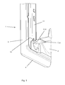
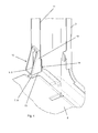
- FIGS. 1 and 3 show a part of a housing 1 for household appliances, such as dryers, washing machines, dishwashers or the like, which include in its basic design a floor module 2 and side walls not shown and a rear wall, wherein on the floor module 2, a front wall 3 is attached.
- the front wall 3 for frameless construction of the housing 1 at its lower transverse side 4 at least two support points 5 and 6, which are placed on provided on the floor module 2 surfaces 7 and 8 or attachable.
- the support points 5 and 6 and in connection with the corresponding surfaces 7 and 8 of the floor module 2 in the immediate vicinity of the provided on the floor module 2 feet 9 of the housing 1 are arranged.
- FIGS. 1 and 2 Here are the support points 5 and 6 of two folded sheet metal tabs 10.
- the metal tabs 10 are, as shown in FIG. 2 can be clearly seen as a right angle surfaces with the formation of portions of the front wall 3 shaped profile 11 bent out. This is especially true in the FIG. 1 to clearly see from the perspective, where below a portion of the folded profile is punched out, with an area the sheet metal tab 10 forming, as a support point 5, 6 is bent out.
- the sheet metal tabs 10 provided with an enamel coating, a lacquer coating or stainless steel and the surfaces 7 and 8 of the floor module 2 form a sliding pairing, which provides the fitter an easy aligned attachment of the front wall 3, as regards the lateral delimitation Front wall shaped profile 11 is done.
- the support points 5 and 6 for connection to the corresponding surfaces 7 and 8 of the floor module 2 consist of plastic elements 12 which are attachable to the front wall 3 forming profile 11.
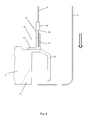
- the plastic elements 12 in punched on the profile 11 of the front wall 3 hole patterns attachable, as shown in the FIG. 6 can be clearly seen in the sectional view.
- the plastic elements 12 are each formed from an angle element, the vertical leg 13 has molded elements 14 for the connection of the hole pattern, wherein the horizontally oriented leg 15 forms a contact point 5, 6 comprehensive surface.
- the molded elements 14 consist of superimposed hooks 16 and 17, wherein the upper hook 16 engages in a hole punching 18 on the profile 11 and wherein the lower hook 17 engages under an edge portion of the profile 11 in the inserted state from below.
- the surfaces 7 and 8, recognizable in the FIGS. 1 . 3 . 4 and 5 the bottom module 2 integrally formed chamfers and chamfers 19, which in particular significantly facilitates the piecing process for the fitter.
Landscapes
- Engineering & Computer Science (AREA)
- Textile Engineering (AREA)
- Casings For Electric Apparatus (AREA)
- Main Body Construction Of Washing Machines And Laundry Dryers (AREA)
Abstract
Description
- Gehäuse für Haushaltsgeräte wie beispielsweise Wäschetrockner, Waschmaschine, Geschirrspülmaschine oder dergleichen.
- Die Erfindung betrifft ein Gehäuse für Haushaltsgeräte wie beispielsweise Wäschetrockner, Waschmaschine, Geschirrspülmaschine oder dergleichen, welches in seiner Grundbauform ein Bodenmodul sowie Seitenwände, eine Rückwand und eine Vorderwand umfasst.
- So sind aus dem Stand der Technik, gemäß der
DE 103 03 131 , derDE 198 23 424 sowie aus derDE 38 13 462 Waschmaschinengehäuse bzw. Gehäuse für Haushaltsgeräte bekannt. Bei diesen aus dem Stand der Technik bekannten Gehäuse gibt es unterschiedliche Gehäusebauformen für die jeweilige Oberfläche oder Montageart, was eine frühe Variantenbildung beim Gehäuseaufbau erfordert. - Der Erfindung stellt sich somit das Problem ein Gehäuse für Haushaltsgeräte bereit zu stellen, welches ein Einheitsgehäuse mit Variantenbildung durch Anbauteile und geeigneter Verbindungstechnik umfasst, welche eine einfache Montage zulässt.
- Das erfindungsgemäße Gehäuse wird ohne einen eigenständigen Innenrahmen gefertigt. Die von außen auf das Gerät wirkenden Lasten werden hierbei passend verteilt, wobei die Erstellung des Gehäuses montagefreundlich ist. Bei der Anbindung der Vorderwand werden vertikal wirkende Lasten auf die Vorderwand in Richtung Fußboden weitergeleitet. Eine Montagefreundlichkeit beim Verbau der Baugruppe Vorderwand wird dadurch bereitgestellt. Bei der erfindungsgemäßen ersten Lösung sind zwei als Blechlaschen ausgebildete Umkantungen an der Vorderwand vorgesehen, die als Auflage aus zwei dafür bestimmte Flächen des Bodenmoduls bestimmt sind. Diese sind dabei sehr nahe an den Anbindungen des Bodenmoduls zu den Füßen angeordnet, so dass der Kraftfluss einen möglichst kurzen geraden Weg nehmen kann. Durch die Gleitpaarung, Emaille, Lack oder Edelstahl an der Vorderwand und Kunststoff für das Bodenmodul und durch die im Blech angeformten Radien, wobei im Kunststoff angeformte Fasen und Einführstege vorhanden sind, rutscht die Vorderwandbodengruppe gut über die Auflage. Die Montageposition der Vorderwandbaugruppe wird für den Monteur so einfacher gestaltet. Bei der Montage des Vorderwandmoduls, bestehend aus Vorderwand und vorderer Luftführung, kann der Monteur dieses noch im leicht schrägen Winkel auf das Bodenmodul absetzen, wobei er sich dann auf das passgenaue Heranschieben des Vorderwandmoduls an das Bodenmodul konzentrieren kann. Dadurch ergibt sich ein sauberes Treffen der beiden Dichtungen in der vorderen Luftführung zum Bodenmodul. Ein weiterer Vorteil der erfindungsgemäße Lösung ist, dass keine extra Auflageteile in der Vorderwand nötig sind, weil die Blechlaschen direkt bei der Herstellung der Vorderwand mitgeformt werden.
- Erfindungsgemäß wird gemäß einer ersten Variante vorgeschlagen, dass die Auflagepunkte und die in Anbindung der korrespondierenden Flächen des Bodenmoduls in unmittelbarer Nähe zu den am Bodenmodul vorgesehenen Standfüßen des Gehäuses angeordnet sind. Dabei bestehen die Auflagepunkte aus zwei umgekanteten Blechlaschen, die als Rechtwinkelflächen unter Bildung von Teilbereichen aus dem die Vorderwand geformten Profil heraus gebogen sind. Wie bereits schon gesagt, bilden die mit einer Emaillebeschichtung, Lackbeschichtung versehenen Blechlaschen bzw. aus Edelstahl gefertigten Blechlaschen und die Fläche des Bodenmoduls hierbei eine Gleitpaarung, was insbesondere für den Monteur ein erleichtertes Ansetzen des Vorderwandmoduls bereit stellt.
- Gemäß einer zweiten Variante wird eine Lösung vorgeschlagen, die aus zwei Kunststoffelementen in der Vorderwand besteht, die als Auflage dienen und wobei diese auf zwei dafür bestimmte Flächen des Bodenmoduls ebenfalls sehr nahe an den Anbindungen des Bodenmoduls zu den Füßen angeordnet sind, so dass der Kraftfluss einen möglichst kurzen, geraden Weg nehmen kann. Dabei wird ein linker und eine rechter Aufnahmeblock vorgesehen, wobei auch eine symmetrische Ausführung denkbar ist. Die beiden Aufnahmeblöcke werden an der Vorderwand vormontiert. Hierzu sind Lochbilder an der Vorderwand für die Aufnahme der Blöcke so gestaltet, dass der Aufnahmeblock unter Anderem jeweils auf zwei horizontalen Vorderwandkanten aufliegt, um die entstehenden Spannungen im Lastfall materialgerecht abfangen zu können. Durch die Gleitpaarung Kunststoff und die im Kunststoff angeformten Radien, Fasen und Einführschrägen rutscht die Vorderwandbaugruppe gut über die Auflage. Die Montageposition der Vorderwandgruppe ist so für den Monteur einfacher zu treffen. Der Monteur kann so bei der Montage das Vorderwandmodul, bestehend aus Vorderwand und vorderer Luftführung, ebenfalls im leicht schrägen Winkel auf dem Bodenmodul absetzen, um sich dann ganz auf das passgenaue Heranschieben des Vorderwandmoduls an das Bodenmodul zu konzentrieren, was ein sauberes Treffen der beiden Dichtungen in der vorderen Luftführung zum Bodenmodul zur Folge hat. Auch bei dieser Ausführung sind extra Auflagenteile in der Vorderwand nicht erforderlich, was die Fertigung der Vorderwand einfacher und das Höhenmaß genauer macht.
- Erfindungsgemäß wird hierzu vorgeschlagen, dass die Auflagepunkte zur Anbindung an die korrespondierenden Flächen des Bodenmoduls aus Kunststoffelementen bestehen, die an das die Vorderwand bildende Profil ansetzbar sind. Hierbei sind die Kunststoffelemente in an dem Profil der Vorderwand gestanzten Lochbildern ansetzbar. Die Kunststoffelemente als solches sind jeweils aus einem Winkelelement geformt, dessen senkrechter Schenkel angeformte Elemente für die Anbindung an das Lochbild aufweisen, wobei der horizontal ausgerichtete Schenkel eine den Auflagepunkt umfassende Fläche bildet. Die angeformten Elemente bestehen hierbei aus übereinander angeformten Haken, wobei der obere Haken in eine Lochstanzung am Profil greift und der untere Haken einen Kantenbereich des Profils untergreift. Somit ergibt sich eine Zweikantenauflage an der Vorderwand.
- In Weiterbildung der Erfindung weisen die Flächen des Bodenmoduls angeformte Fasen und Einführungsschrägen auf, die insbesondere ein leichtes Ansetzen der Vorderwandgruppe an das Bodenmodul für den Monteur ermöglichen.
- Ein Ausführungsbeispiel der Erfindung ist in den Zeichnungen rein schematisch dargestellt und wird nachfolgend näher beschrieben. Es zeigt:
- Figur 1
- eine perspektivische Darstellung des unteren Eckbereichs des Gehäuses von Bodenmodul und Vorderwand im angesetzten Zustand am Bodenmodul in einer ersten Ausführungsform;
- Figur 2
- eine geschnittene Ansicht von Bodenmodul mit angesetzter Vorderwand gemäß der
Figur 1 ; - Figur 3
- eine weitere perspektivische Darstellung von Vorderwand und Bodenmodul gemäß einer zweiten Ausführungsform, ebenfalls im angesetzten Zustand der Vorderwand an das Bodenmodul;
- Figur 4
- eine Detailansicht des Auflagepunktes auf dem Bodenmodul in einer ersten Ansicht gemäß der
Figur 3 ; - Figur 5
- eine weitere Darstellung des Auflagepunktes in einer anderen Blickrichtung ebenfalls gemäß der
Figur 3 ; und - Figur 6
- eine geschnittene Darstellung des Auflagepunktes gemäß der zweiten Ausführungsform.
- Die
Figuren 1 und3 zeigen einen Teil eines Gehäuses 1 für Haushaltsgeräte, wie beispielsweise Wäschetrockner, Waschmaschinen, Geschirrspüler oder dergleichen, welches in seiner Grundbauform ein Bodenmodul 2 sowie nicht näher dargestellte Seitenwände und eine Rückwand umfassen, wobei an dem Bodenmodul 2 eine Vorderwand 3 angesetzt ist. Wie insbesondere aus der Zusammenschau derFiguren 1 und3 zu erkennen ist, weist die Vorderwand 3 zum rahmenlosen Aufbau des Gehäuses 1 an ihrer unteren Querseite 4 wenigstens zwei Auflagepunkte 5 und 6 auf, die auf an dem Bodenmodul 2 vorgesehenen Flächen 7 und 8 aufsetzbar bzw. ansetzbar sind. Wie insbesondere aus derFigur 2 und6 deutlich wird, sind die Auflagepunkte 5 und 6 und die in Anbindung der korrespondierenden Flächen 7 und 8 des Bodenmoduls 2 in unmittelbarer Nähe zu den am Bodenmodul 2 vorgesehenen Standfüßen 9 des Gehäuses 1 angeordnet. - Gemäß der ersten Ausführungsform der Erfindung, dargestellt in den
Figuren 1 und2 , bestehen hierbei die Auflagepunkte 5 und 6 aus zwei umgekanteten Blechlaschen 10. Die Blechlaschen 10 sind, wie aus derFigur 2 deutlich zu erkennen ist, als Rechtwinkelflächen unter Bildung von Teilbereichen aus dem die Vorderwand 3 geformten Profil 11 heraus gebogen. Dies ist insbesondere in derFigur 1 aus der Perspektive deutlich zu erkennen, wo unten ein Teilbereich aus der abgekanteten Profilierung herausgestanzt ist, wobei ein Bereich die Blechlasche 10 bildend, als Auflagepunkt 5, 6 heraus gebogen ist. Dabei bilden die mit einer Emaillebeschichtung, einer Lackbeschichtung oder Edelstahl versehenen Blechlaschen 10 und die Flächen 7 und 8 des Bodenmoduls 2 eine Gleitpaarung, was insbesondere für den Monteur ein leichtes ausgerichtetes Ansetzen der Vorderwand 3 bereitstellt, da hinsichtlich der seitlichen Begrenzung dies durch das aus der Vorderwand geformte Profil 11 erfolgt. - Gemäß der
Figuren 3 ,4 ,5 und6 wird eine zweite Lösung gezeigt, wobei hierbei die Auflagepunkte 5 und 6 zur Anbindung an die korrespondierenden Flächen 7 und 8 des Bodenmoduls 2 aus Kunststoffelementen 12 bestehen, die an das die Vorderwand 3 bildende Profil 11 ansetzbar sind. Wie aus der Zusammenschau derFiguren 4 und5 ersichtlich, sind die Kunststoffelemente 12 in an dem Profil 11 der Vorderwand 3 gestanzten Lochbildern ansetzbar, wie dies in derFigur 6 in der geschnittenen Darstellung deutlich zu erkennen ist. Die Kunststoffelemente 12 sind jeweils aus einem Winkelelement geformt, dessen senkrechter Schenkel 13 angeformte Elemente 14 für die Anbindung des Lochbildes aufweist, wobei der horizontal ausgerichtete Schenkel 15 eine den Anlagepunkt 5, 6 umfassende Fläche bildet. Wie aus derFigur 6 deutlich zu erkennen ist, bestehen die angeformten Elemente 14 aus übereinander angeformten Haken 16 und 17, wobei der obere Haken 16 in eine Lochstanzung 18 am Profil 11 greift und wobei der untere Haken 17 einen Kantenbereich des Profils 11 im eingefügten Zustand von unten her untergreift. Somit ergibt sich eine formschlüssige stabile Einbindung des Winkelelementes an dem Kantenprofil der Vorderwand 3. Wie insbesondere schon erwähnt, weisen dabei die Flächen 7 und 8, erkennbar in denFiguren 1 ,3 ,4 und5 , des Bodenmoduls 2 angeformte Fasen und Einführschrägen 19 auf, was insbesondere den Ansetzvorgang für den Monteur wesentlich erleichtert.
Claims (10)
- Gehäuse (1) für Haushaltsgeräte wie beispielsweise Wäschetrockner, Waschmaschine, Geschirrspülmaschine oder dergleichen, welches in seiner Grundbauform ein Bodenmodul (2) sowie Seitenwände und eine Rückwand und eine Vorderwand (3) umfasst,
dadurch gekennzeichnet,
dass die Vorderwand (3) zum rahmenlosen Aufbau des Gehäuses (1) an ihrer unteren Querseite (4) wenigstens zwei Auflagepunkte (5) und (6) aufweist, die auf an dem Bodenmodul (2) vorgesehenen Flächen (7) und (8) aufsetzbar bzw. ansetzbar sind. - Gehäuse nach Anspruch 1,
dadurch gekennzeichnet,
dass die Auflagepunkte (5) und (6) und die in Anbindung der korrespondierenden Flächen (7) und (8) des Bodenmoduls (2) in unmittelbarer Nähe zu den am Bodenmodul (2) vorgesehenen Standfüßen (9) des Gehäuses (1) angeordnet sind. - Gehäuse nach Anspruch 2,
dadurch gekennzeichnet,
dass die Auflagepunkte (5) und (6) aus zwei umgekanteten Blechlaschen (10) bestehen. - Gehäuse nach Anspruch 3,
dadurch gekennzeichnet,
dass die Blechlaschen (10) als Rechtwinkelflächen unter Bildung von Teilbereichen aus dem die Vorderwand (3) geformten Profil (11) herausgebogen sind. - Gehäuse nach Anspruch 4,
dadurch gekennzeichnet,
dass die mit einer Emaille-, Lack- oder Edelstahlbeschichtung versehenen Blechlaschen (10) und die Flächen (7) und (8) des Bodenmoduls (2) eine Gleitpaarung bilden. - Gehäuse nach Anspruch 1 und 2,
dadurch gekennzeichnet,
dass die Auflagepunkte (5) und (6) zur Anbindung an die korrespondierenden Flächen (7) und (8) des Bodenmoduls (2) aus Kunststoffelementen (12) bestehen, die an das die Vorderwand (3) bildende Profil (11) ansetzbar sind. - Gehäuse nach Anspruch 6,
dadurch gekennzeichnet,
dass die Kunststoffelemente (12) in an dem Profil (11) der Vorderwand (3) gestanzten Lochbildern ansetzbar sind. - Gehäuse nach Anspruch 7,
dadurch gekennzeichnet,
dass die Kunststoffelemente (12) jeweils aus einem Winkelelement geformt sind, dessen senkrechter Schenkel (13) angeformte Elemente (14) für die Anbindung an das Lochbild aufweist, wobei der horizontal ausgerichtete Schenkel (15) eine den Auflagepunkt (5, 6) umfassende Fläche bildet. - Gehäuse nach Anspruch 8,
dadurch gekennzeichnet,
dass die angeformten Elemente (14) aus übereinander angeformten Haken (16) und (17) bestehen, wobei der obere Haken (16) in eine Lochstanzung (18) am Profil (11) greift und der untere Haken (17) einen Kantenbereich des Profils (11) untergreift. - Gehäuse nach Anspruch 1 bis 9,
dadurch gekennzeichnet,
dass die Flächen (7) und (8) des Bodenmoduls (2) angeformte Fasen und Einführschrägen (19) aufweisen.
Applications Claiming Priority (1)
| Application Number | Priority Date | Filing Date | Title |
|---|---|---|---|
| DE102013102505.6A DE102013102505A1 (de) | 2013-03-13 | 2013-03-13 | Gehäuse für Haushaltsgeräte wie beispielsweise Wäschetrockner, Waschmaschine, Geschirrspülmaschine oder dergleichen |
Publications (3)
| Publication Number | Publication Date |
|---|---|
| EP2777470A2 true EP2777470A2 (de) | 2014-09-17 |
| EP2777470A3 EP2777470A3 (de) | 2014-10-01 |
| EP2777470B1 EP2777470B1 (de) | 2016-10-26 |
Family
ID=50238287
Family Applications (1)
| Application Number | Title | Priority Date | Filing Date |
|---|---|---|---|
| EP14158850.9A Not-in-force EP2777470B1 (de) | 2013-03-13 | 2014-03-11 | Gehäuse für Haushaltsgeräte wie beispielsweise Wäschetrockner, Waschmaschine, Geschirrspülmaschine oder dergleichen |
Country Status (2)
| Country | Link |
|---|---|
| EP (1) | EP2777470B1 (de) |
| DE (1) | DE102013102505A1 (de) |
Citations (3)
| Publication number | Priority date | Publication date | Assignee | Title |
|---|---|---|---|---|
| DE3813462A1 (de) | 1987-04-21 | 1988-11-10 | Candy Ind Spa | Waschmaschinengehaeuse |
| DE19823424A1 (de) | 1998-05-26 | 1999-12-02 | Aeg Hausgeraete Gmbh | Gerätegehäuse, insbesondere für Haushaltsgroßgeräte |
| DE10303131A1 (de) | 2003-01-28 | 2004-07-29 | Electrolux Home Products Corporation N.V. | Haushaltgerät und Gehäuse für das Haushaltgerät |
Family Cites Families (10)
| Publication number | Priority date | Publication date | Assignee | Title |
|---|---|---|---|---|
| JPH053993A (ja) * | 1991-06-27 | 1993-01-14 | Sharp Corp | ドラム式洗濯乾燥機等の前パネル取り付け構造 |
| US5584549A (en) * | 1995-04-26 | 1996-12-17 | General Electric Company | Front serviceable appliance cabinet |
| AU2003251176B2 (en) * | 2002-07-31 | 2006-07-13 | Lg Electronics Inc. | Cabinet for home appliance |
| AU2003262464B2 (en) * | 2002-11-28 | 2006-07-06 | Lg Electronics Inc. | Washing machine |
| KR101163227B1 (ko) * | 2005-04-28 | 2012-07-05 | 엘지전자 주식회사 | 건조기 |
| DE102006001437A1 (de) * | 2006-01-10 | 2007-07-12 | Miele & Cie. Kg | Gehäuse für eine frontbeschickbare Wäschebehandlungsmaschine |
| DE102006005770B4 (de) * | 2006-02-07 | 2009-06-25 | Miele & Cie. Kg | Wäschebehandlungsmaschine mit Sicherheitseinrichtung |
| KR20120041428A (ko) * | 2010-10-21 | 2012-05-02 | 삼성전자주식회사 | 세탁기 및 그 조립구조 |
| WO2012062673A1 (en) * | 2010-11-12 | 2012-05-18 | Arcelik Anonim Sirketi | A washer/dryer comprising a connection member |
| EP2638200B1 (de) * | 2010-11-12 | 2016-03-23 | Arçelik Anonim Sirketi | Eine waschmaschine / trockner wobei einfache montage vorgesehen ist |
-
2013
- 2013-03-13 DE DE102013102505.6A patent/DE102013102505A1/de not_active Ceased
-
2014
- 2014-03-11 EP EP14158850.9A patent/EP2777470B1/de not_active Not-in-force
Patent Citations (3)
| Publication number | Priority date | Publication date | Assignee | Title |
|---|---|---|---|---|
| DE3813462A1 (de) | 1987-04-21 | 1988-11-10 | Candy Ind Spa | Waschmaschinengehaeuse |
| DE19823424A1 (de) | 1998-05-26 | 1999-12-02 | Aeg Hausgeraete Gmbh | Gerätegehäuse, insbesondere für Haushaltsgroßgeräte |
| DE10303131A1 (de) | 2003-01-28 | 2004-07-29 | Electrolux Home Products Corporation N.V. | Haushaltgerät und Gehäuse für das Haushaltgerät |
Also Published As
| Publication number | Publication date |
|---|---|
| EP2777470B1 (de) | 2016-10-26 |
| EP2777470A3 (de) | 2014-10-01 |
| DE102013102505A1 (de) | 2014-09-18 |
Similar Documents
| Publication | Publication Date | Title |
|---|---|---|
| EP0943721B2 (de) | Gehäuse für eine frontbeschickbare Wäschebehandlungsmaschine | |
| DE102014101320A1 (de) | Entwässerungsabdeckung | |
| EP2594182A1 (de) | Gehäuse für Haushaltsgeräte wie Waschmaschinen, Wäschetrockner oder Geschirrspülmaschinen | |
| DE102010015885A1 (de) | Elektrisches Verteilergehäuse | |
| EP2778276B1 (de) | Gehäuse für Haushaltsgeräte sowie Verfahren zur Herrichtung eines Gehäuses für Haushaltsgeräte | |
| DE102014111784C5 (de) | Vorrichtung für einen beabstandet zu einer Wand im Boden eines Raumes angeordneten Bodenablauf | |
| DE102015122260A1 (de) | Trennwand | |
| EP2777470B1 (de) | Gehäuse für Haushaltsgeräte wie beispielsweise Wäschetrockner, Waschmaschine, Geschirrspülmaschine oder dergleichen | |
| DE102013001234B4 (de) | Anordnung einer Vorrichtung für einen in der Nähe einer Wand angeordneten Bodenablauf | |
| EP2778278B1 (de) | Gehäuse für haushaltsgeräte wie beispielsweise einen wäschetrockner, eine waschmaschine, oder dergleichen | |
| DE19849368A1 (de) | Eckverbindung für L-förmige Rahmenprofile | |
| EP2778273B1 (de) | Gehäuse für haushaltsgeräte wie beispielsweise wäschetrockner, waschmaschine, geschirrspülmaschine oder dergleichen | |
| DE102005059306B4 (de) | Trägergestell für elektrische Verteiler | |
| EP1705282A1 (de) | Dampfbügeltisch | |
| DE10332681A1 (de) | Verbindungssystem für Profilschienen | |
| DE202008011099U1 (de) | Filter für lufttechnische Anlagen mit mehreren jeweils eckig, insbesondere rechteckig, ausgebildeten Zellenrahmen | |
| DE19908391C1 (de) | Verschlußsystem für Wandverkleidungsplatten | |
| EP2777469B1 (de) | Gehäuse für Haushaltsgeräte wie beispielsweise Wäschetrockner, Waschmaschine, Geschirrspülmaschine oder dergleichen | |
| DE29819364U1 (de) | Anordnung sowie Dichtungselement zur Abdichtung einer Verbindung zwischen einer Wand eines Raumes und einer Zarge einer Bade- oder Duschwanne | |
| EP2801656B1 (de) | Haushaltgerät mit einer Revisionsklappe und mit einem Scharnierblock | |
| DE69004700T2 (de) | Gehäuse für elektrische Haushaltsgeräte, insbesondere für Waschmaschinen. | |
| EP2778274B1 (de) | Gehäuse für Haushaltsgeräte wie beispielsweise Wäschetrockner, Waschmaschine, Geschirrspülmaschine oder dergleichen | |
| DE4031223A1 (de) | U-foermiger grundrahmen zum aufbau eines gehaeuses fuer ein haushaltgeraet | |
| WO2016087209A1 (de) | Haushaltsgerät | |
| DE102011080190A1 (de) | Hausgeräteanordnung mit einem ersten und zumindest einem zweiten Hausgerät |
Legal Events
| Date | Code | Title | Description |
|---|---|---|---|
| PUAL | Search report despatched |
Free format text: ORIGINAL CODE: 0009013 |
|
| 17P | Request for examination filed |
Effective date: 20140311 |
|
| AK | Designated contracting states |
Kind code of ref document: A2 Designated state(s): AL AT BE BG CH CY CZ DE DK EE ES FI FR GB GR HR HU IE IS IT LI LT LU LV MC MK MT NL NO PL PT RO RS SE SI SK SM TR |
|
| AX | Request for extension of the european patent |
Extension state: BA ME |
|
| PUAI | Public reference made under article 153(3) epc to a published international application that has entered the european phase |
Free format text: ORIGINAL CODE: 0009012 |
|
| AK | Designated contracting states |
Kind code of ref document: A3 Designated state(s): AL AT BE BG CH CY CZ DE DK EE ES FI FR GB GR HR HU IE IS IT LI LT LU LV MC MK MT NL NO PL PT RO RS SE SI SK SM TR |
|
| AX | Request for extension of the european patent |
Extension state: BA ME |
|
| RIC1 | Information provided on ipc code assigned before grant |
Ipc: D06F 58/20 20060101ALI20140822BHEP Ipc: A47L 15/42 20060101AFI20140822BHEP Ipc: D06F 39/12 20060101ALI20140822BHEP |
|
| R17P | Request for examination filed (corrected) |
Effective date: 20150401 |
|
| RBV | Designated contracting states (corrected) |
Designated state(s): AL AT BE BG CH CY CZ DE DK EE ES FI FR GB GR HR HU IE IS IT LI LT LU LV MC MK MT NL NO PL PT RO RS SE SI SK SM TR |
|
| 17Q | First examination report despatched |
Effective date: 20150827 |
|
| GRAP | Despatch of communication of intention to grant a patent |
Free format text: ORIGINAL CODE: EPIDOSNIGR1 |
|
| INTG | Intention to grant announced |
Effective date: 20160603 |
|
| RIN1 | Information on inventor provided before grant (corrected) |
Inventor name: EWERT, ANDREAS Inventor name: WIEBE, PETER Inventor name: REDER, KARIN Inventor name: MOLL, FELIX |
|
| GRAS | Grant fee paid |
Free format text: ORIGINAL CODE: EPIDOSNIGR3 |
|
| GRAA | (expected) grant |
Free format text: ORIGINAL CODE: 0009210 |
|
| AK | Designated contracting states |
Kind code of ref document: B1 Designated state(s): AL AT BE BG CH CY CZ DE DK EE ES FI FR GB GR HR HU IE IS IT LI LT LU LV MC MK MT NL NO PL PT RO RS SE SI SK SM TR |
|
| REG | Reference to a national code |
Ref country code: GB Ref legal event code: FG4D Free format text: NOT ENGLISH |
|
| REG | Reference to a national code |
Ref country code: CH Ref legal event code: EP |
|
| REG | Reference to a national code |
Ref country code: DE Ref legal event code: R084 Ref document number: 502014001771 Country of ref document: DE |
|
| REG | Reference to a national code |
Ref country code: AT Ref legal event code: REF Ref document number: 839372 Country of ref document: AT Kind code of ref document: T Effective date: 20161115 |
|
| REG | Reference to a national code |
Ref country code: IE Ref legal event code: FG4D Free format text: LANGUAGE OF EP DOCUMENT: GERMAN |
|
| REG | Reference to a national code |
Ref country code: GB Ref legal event code: 746 Effective date: 20161104 |
|
| REG | Reference to a national code |
Ref country code: DE Ref legal event code: R096 Ref document number: 502014001771 Country of ref document: DE |
|
| REG | Reference to a national code |
Ref country code: LT Ref legal event code: MG4D |
|
| PG25 | Lapsed in a contracting state [announced via postgrant information from national office to epo] |
Ref country code: LV Free format text: LAPSE BECAUSE OF FAILURE TO SUBMIT A TRANSLATION OF THE DESCRIPTION OR TO PAY THE FEE WITHIN THE PRESCRIBED TIME-LIMIT Effective date: 20161026 |
|
| REG | Reference to a national code |
Ref country code: NL Ref legal event code: MP Effective date: 20161026 |
|
| REG | Reference to a national code |
Ref country code: FR Ref legal event code: PLFP Year of fee payment: 4 |
|
| PG25 | Lapsed in a contracting state [announced via postgrant information from national office to epo] |
Ref country code: NO Free format text: LAPSE BECAUSE OF FAILURE TO SUBMIT A TRANSLATION OF THE DESCRIPTION OR TO PAY THE FEE WITHIN THE PRESCRIBED TIME-LIMIT Effective date: 20170126 Ref country code: LT Free format text: LAPSE BECAUSE OF FAILURE TO SUBMIT A TRANSLATION OF THE DESCRIPTION OR TO PAY THE FEE WITHIN THE PRESCRIBED TIME-LIMIT Effective date: 20161026 Ref country code: SE Free format text: LAPSE BECAUSE OF FAILURE TO SUBMIT A TRANSLATION OF THE DESCRIPTION OR TO PAY THE FEE WITHIN THE PRESCRIBED TIME-LIMIT Effective date: 20161026 Ref country code: GR Free format text: LAPSE BECAUSE OF FAILURE TO SUBMIT A TRANSLATION OF THE DESCRIPTION OR TO PAY THE FEE WITHIN THE PRESCRIBED TIME-LIMIT Effective date: 20170127 |
|
| PG25 | Lapsed in a contracting state [announced via postgrant information from national office to epo] |
Ref country code: PL Free format text: LAPSE BECAUSE OF FAILURE TO SUBMIT A TRANSLATION OF THE DESCRIPTION OR TO PAY THE FEE WITHIN THE PRESCRIBED TIME-LIMIT Effective date: 20161026 Ref country code: ES Free format text: LAPSE BECAUSE OF FAILURE TO SUBMIT A TRANSLATION OF THE DESCRIPTION OR TO PAY THE FEE WITHIN THE PRESCRIBED TIME-LIMIT Effective date: 20161026 Ref country code: RS Free format text: LAPSE BECAUSE OF FAILURE TO SUBMIT A TRANSLATION OF THE DESCRIPTION OR TO PAY THE FEE WITHIN THE PRESCRIBED TIME-LIMIT Effective date: 20161026 Ref country code: PT Free format text: LAPSE BECAUSE OF FAILURE TO SUBMIT A TRANSLATION OF THE DESCRIPTION OR TO PAY THE FEE WITHIN THE PRESCRIBED TIME-LIMIT Effective date: 20170227 Ref country code: HR Free format text: LAPSE BECAUSE OF FAILURE TO SUBMIT A TRANSLATION OF THE DESCRIPTION OR TO PAY THE FEE WITHIN THE PRESCRIBED TIME-LIMIT Effective date: 20161026 Ref country code: IS Free format text: LAPSE BECAUSE OF FAILURE TO SUBMIT A TRANSLATION OF THE DESCRIPTION OR TO PAY THE FEE WITHIN THE PRESCRIBED TIME-LIMIT Effective date: 20170226 Ref country code: NL Free format text: LAPSE BECAUSE OF FAILURE TO SUBMIT A TRANSLATION OF THE DESCRIPTION OR TO PAY THE FEE WITHIN THE PRESCRIBED TIME-LIMIT Effective date: 20161026 Ref country code: FI Free format text: LAPSE BECAUSE OF FAILURE TO SUBMIT A TRANSLATION OF THE DESCRIPTION OR TO PAY THE FEE WITHIN THE PRESCRIBED TIME-LIMIT Effective date: 20161026 |
|
| REG | Reference to a national code |
Ref country code: DE Ref legal event code: R097 Ref document number: 502014001771 Country of ref document: DE |
|
| PG25 | Lapsed in a contracting state [announced via postgrant information from national office to epo] |
Ref country code: RO Free format text: LAPSE BECAUSE OF FAILURE TO SUBMIT A TRANSLATION OF THE DESCRIPTION OR TO PAY THE FEE WITHIN THE PRESCRIBED TIME-LIMIT Effective date: 20161026 Ref country code: CZ Free format text: LAPSE BECAUSE OF FAILURE TO SUBMIT A TRANSLATION OF THE DESCRIPTION OR TO PAY THE FEE WITHIN THE PRESCRIBED TIME-LIMIT Effective date: 20161026 Ref country code: SK Free format text: LAPSE BECAUSE OF FAILURE TO SUBMIT A TRANSLATION OF THE DESCRIPTION OR TO PAY THE FEE WITHIN THE PRESCRIBED TIME-LIMIT Effective date: 20161026 Ref country code: DK Free format text: LAPSE BECAUSE OF FAILURE TO SUBMIT A TRANSLATION OF THE DESCRIPTION OR TO PAY THE FEE WITHIN THE PRESCRIBED TIME-LIMIT Effective date: 20161026 Ref country code: EE Free format text: LAPSE BECAUSE OF FAILURE TO SUBMIT A TRANSLATION OF THE DESCRIPTION OR TO PAY THE FEE WITHIN THE PRESCRIBED TIME-LIMIT Effective date: 20161026 |
|
| PG25 | Lapsed in a contracting state [announced via postgrant information from national office to epo] |
Ref country code: IT Free format text: LAPSE BECAUSE OF FAILURE TO SUBMIT A TRANSLATION OF THE DESCRIPTION OR TO PAY THE FEE WITHIN THE PRESCRIBED TIME-LIMIT Effective date: 20161026 Ref country code: BG Free format text: LAPSE BECAUSE OF FAILURE TO SUBMIT A TRANSLATION OF THE DESCRIPTION OR TO PAY THE FEE WITHIN THE PRESCRIBED TIME-LIMIT Effective date: 20170126 Ref country code: SM Free format text: LAPSE BECAUSE OF FAILURE TO SUBMIT A TRANSLATION OF THE DESCRIPTION OR TO PAY THE FEE WITHIN THE PRESCRIBED TIME-LIMIT Effective date: 20161026 |
|
| PLBE | No opposition filed within time limit |
Free format text: ORIGINAL CODE: 0009261 |
|
| STAA | Information on the status of an ep patent application or granted ep patent |
Free format text: STATUS: NO OPPOSITION FILED WITHIN TIME LIMIT |
|
| 26N | No opposition filed |
Effective date: 20170727 |
|
| REG | Reference to a national code |
Ref country code: CH Ref legal event code: PL |
|
| PG25 | Lapsed in a contracting state [announced via postgrant information from national office to epo] |
Ref country code: SI Free format text: LAPSE BECAUSE OF FAILURE TO SUBMIT A TRANSLATION OF THE DESCRIPTION OR TO PAY THE FEE WITHIN THE PRESCRIBED TIME-LIMIT Effective date: 20161026 Ref country code: MC Free format text: LAPSE BECAUSE OF FAILURE TO SUBMIT A TRANSLATION OF THE DESCRIPTION OR TO PAY THE FEE WITHIN THE PRESCRIBED TIME-LIMIT Effective date: 20161026 |
|
| REG | Reference to a national code |
Ref country code: IE Ref legal event code: MM4A |
|
| PG25 | Lapsed in a contracting state [announced via postgrant information from national office to epo] |
Ref country code: LU Free format text: LAPSE BECAUSE OF NON-PAYMENT OF DUE FEES Effective date: 20170311 |
|
| PG25 | Lapsed in a contracting state [announced via postgrant information from national office to epo] |
Ref country code: LI Free format text: LAPSE BECAUSE OF NON-PAYMENT OF DUE FEES Effective date: 20170331 Ref country code: CH Free format text: LAPSE BECAUSE OF NON-PAYMENT OF DUE FEES Effective date: 20170331 Ref country code: IE Free format text: LAPSE BECAUSE OF NON-PAYMENT OF DUE FEES Effective date: 20170311 |
|
| REG | Reference to a national code |
Ref country code: BE Ref legal event code: MM Effective date: 20170331 |
|
| REG | Reference to a national code |
Ref country code: FR Ref legal event code: PLFP Year of fee payment: 5 |
|
| PG25 | Lapsed in a contracting state [announced via postgrant information from national office to epo] |
Ref country code: BE Free format text: LAPSE BECAUSE OF NON-PAYMENT OF DUE FEES Effective date: 20170331 |
|
| PG25 | Lapsed in a contracting state [announced via postgrant information from national office to epo] |
Ref country code: MT Free format text: LAPSE BECAUSE OF FAILURE TO SUBMIT A TRANSLATION OF THE DESCRIPTION OR TO PAY THE FEE WITHIN THE PRESCRIBED TIME-LIMIT Effective date: 20161026 |
|
| PG25 | Lapsed in a contracting state [announced via postgrant information from national office to epo] |
Ref country code: HU Free format text: LAPSE BECAUSE OF FAILURE TO SUBMIT A TRANSLATION OF THE DESCRIPTION OR TO PAY THE FEE WITHIN THE PRESCRIBED TIME-LIMIT; INVALID AB INITIO Effective date: 20140311 |
|
| PG25 | Lapsed in a contracting state [announced via postgrant information from national office to epo] |
Ref country code: CY Free format text: LAPSE BECAUSE OF NON-PAYMENT OF DUE FEES Effective date: 20161026 |
|
| PG25 | Lapsed in a contracting state [announced via postgrant information from national office to epo] |
Ref country code: MK Free format text: LAPSE BECAUSE OF FAILURE TO SUBMIT A TRANSLATION OF THE DESCRIPTION OR TO PAY THE FEE WITHIN THE PRESCRIBED TIME-LIMIT Effective date: 20161026 |
|
| PG25 | Lapsed in a contracting state [announced via postgrant information from national office to epo] |
Ref country code: TR Free format text: LAPSE BECAUSE OF FAILURE TO SUBMIT A TRANSLATION OF THE DESCRIPTION OR TO PAY THE FEE WITHIN THE PRESCRIBED TIME-LIMIT Effective date: 20161026 |
|
| PG25 | Lapsed in a contracting state [announced via postgrant information from national office to epo] |
Ref country code: AL Free format text: LAPSE BECAUSE OF FAILURE TO SUBMIT A TRANSLATION OF THE DESCRIPTION OR TO PAY THE FEE WITHIN THE PRESCRIBED TIME-LIMIT Effective date: 20161026 |
|
| REG | Reference to a national code |
Ref country code: AT Ref legal event code: MM01 Ref document number: 839372 Country of ref document: AT Kind code of ref document: T Effective date: 20190311 |
|
| PG25 | Lapsed in a contracting state [announced via postgrant information from national office to epo] |
Ref country code: AT Free format text: LAPSE BECAUSE OF NON-PAYMENT OF DUE FEES Effective date: 20190311 |
|
| P01 | Opt-out of the competence of the unified patent court (upc) registered |
Effective date: 20230529 |
|
| PGFP | Annual fee paid to national office [announced via postgrant information from national office to epo] |
Ref country code: DE Payment date: 20240331 Year of fee payment: 11 Ref country code: GB Payment date: 20240319 Year of fee payment: 11 |
|
| PGFP | Annual fee paid to national office [announced via postgrant information from national office to epo] |
Ref country code: FR Payment date: 20240326 Year of fee payment: 11 |
|
| REG | Reference to a national code |
Ref country code: DE Ref legal event code: R119 Ref document number: 502014001771 Country of ref document: DE |
|
| GBPC | Gb: european patent ceased through non-payment of renewal fee |
Effective date: 20250311 |
|
| PG25 | Lapsed in a contracting state [announced via postgrant information from national office to epo] |
Ref country code: DE Free format text: LAPSE BECAUSE OF NON-PAYMENT OF DUE FEES Effective date: 20251001 |
|
| PG25 | Lapsed in a contracting state [announced via postgrant information from national office to epo] |
Ref country code: GB Free format text: LAPSE BECAUSE OF NON-PAYMENT OF DUE FEES Effective date: 20250311 |
|
| PG25 | Lapsed in a contracting state [announced via postgrant information from national office to epo] |
Ref country code: FR Free format text: LAPSE BECAUSE OF NON-PAYMENT OF DUE FEES Effective date: 20250331 |