EP2776216B1 - Appareil robot et méthode de commande pour reprendre le fonctionnement après une pause. - Google Patents
Appareil robot et méthode de commande pour reprendre le fonctionnement après une pause. Download PDFInfo
- Publication number
- EP2776216B1 EP2776216B1 EP12848273.4A EP12848273A EP2776216B1 EP 2776216 B1 EP2776216 B1 EP 2776216B1 EP 12848273 A EP12848273 A EP 12848273A EP 2776216 B1 EP2776216 B1 EP 2776216B1
- Authority
- EP
- European Patent Office
- Prior art keywords
- robot
- pose
- sensor
- sensor measurements
- orientation
- Prior art date
- Legal status (The legal status is an assumption and is not a legal conclusion. Google has not performed a legal analysis and makes no representation as to the accuracy of the status listed.)
- Active
Links
Images


Classifications
-
- G—PHYSICS
- G05—CONTROLLING; REGULATING
- G05D—SYSTEMS FOR CONTROLLING OR REGULATING NON-ELECTRIC VARIABLES
- G05D1/00—Control of position, course, altitude or attitude of land, water, air or space vehicles, e.g. using automatic pilots
- G05D1/02—Control of position or course in two dimensions
- G05D1/021—Control of position or course in two dimensions specially adapted to land vehicles
- G05D1/0231—Control of position or course in two dimensions specially adapted to land vehicles using optical position detecting means
- G05D1/0234—Control of position or course in two dimensions specially adapted to land vehicles using optical position detecting means using optical markers or beacons
-
- G—PHYSICS
- G01—MEASURING; TESTING
- G01C—MEASURING DISTANCES, LEVELS OR BEARINGS; SURVEYING; NAVIGATION; GYROSCOPIC INSTRUMENTS; PHOTOGRAMMETRY OR VIDEOGRAMMETRY
- G01C21/00—Navigation; Navigational instruments not provided for in groups G01C1/00 - G01C19/00
- G01C21/10—Navigation; Navigational instruments not provided for in groups G01C1/00 - G01C19/00 by using measurements of speed or acceleration
- G01C21/12—Navigation; Navigational instruments not provided for in groups G01C1/00 - G01C19/00 by using measurements of speed or acceleration executed aboard the object being navigated; Dead reckoning
-
- G—PHYSICS
- G01—MEASURING; TESTING
- G01S—RADIO DIRECTION-FINDING; RADIO NAVIGATION; DETERMINING DISTANCE OR VELOCITY BY USE OF RADIO WAVES; LOCATING OR PRESENCE-DETECTING BY USE OF THE REFLECTION OR RERADIATION OF RADIO WAVES; ANALOGOUS ARRANGEMENTS USING OTHER WAVES
- G01S17/00—Systems using the reflection or reradiation of electromagnetic waves other than radio waves, e.g. lidar systems
- G01S17/02—Systems using the reflection of electromagnetic waves other than radio waves
- G01S17/06—Systems determining position data of a target
-
- G—PHYSICS
- G05—CONTROLLING; REGULATING
- G05D—SYSTEMS FOR CONTROLLING OR REGULATING NON-ELECTRIC VARIABLES
- G05D1/00—Control of position, course, altitude or attitude of land, water, air or space vehicles, e.g. using automatic pilots
- G05D1/02—Control of position or course in two dimensions
- G05D1/021—Control of position or course in two dimensions specially adapted to land vehicles
- G05D1/0231—Control of position or course in two dimensions specially adapted to land vehicles using optical position detecting means
-
- G—PHYSICS
- G05—CONTROLLING; REGULATING
- G05D—SYSTEMS FOR CONTROLLING OR REGULATING NON-ELECTRIC VARIABLES
- G05D1/00—Control of position, course, altitude or attitude of land, water, air or space vehicles, e.g. using automatic pilots
- G05D1/02—Control of position or course in two dimensions
- G05D1/021—Control of position or course in two dimensions specially adapted to land vehicles
- G05D1/0268—Control of position or course in two dimensions specially adapted to land vehicles using internal positioning means
- G05D1/0274—Control of position or course in two dimensions specially adapted to land vehicles using internal positioning means using mapping information stored in a memory device
-
- G—PHYSICS
- G05—CONTROLLING; REGULATING
- G05D—SYSTEMS FOR CONTROLLING OR REGULATING NON-ELECTRIC VARIABLES
- G05D1/00—Control of position, course, altitude or attitude of land, water, air or space vehicles, e.g. using automatic pilots
- G05D1/02—Control of position or course in two dimensions
- G05D1/021—Control of position or course in two dimensions specially adapted to land vehicles
- G05D1/0276—Control of position or course in two dimensions specially adapted to land vehicles using signals provided by a source external to the vehicle
- G05D1/028—Control of position or course in two dimensions specially adapted to land vehicles using signals provided by a source external to the vehicle using a RF signal
-
- G—PHYSICS
- G05—CONTROLLING; REGULATING
- G05D—SYSTEMS FOR CONTROLLING OR REGULATING NON-ELECTRIC VARIABLES
- G05D1/00—Control of position, course, altitude or attitude of land, water, air or space vehicles, e.g. using automatic pilots
- G05D1/02—Control of position or course in two dimensions
- G05D1/021—Control of position or course in two dimensions specially adapted to land vehicles
- G05D1/0268—Control of position or course in two dimensions specially adapted to land vehicles using internal positioning means
- G05D1/0272—Control of position or course in two dimensions specially adapted to land vehicles using internal positioning means comprising means for registering the travel distance, e.g. revolutions of wheels
-
- Y—GENERAL TAGGING OF NEW TECHNOLOGICAL DEVELOPMENTS; GENERAL TAGGING OF CROSS-SECTIONAL TECHNOLOGIES SPANNING OVER SEVERAL SECTIONS OF THE IPC; TECHNICAL SUBJECTS COVERED BY FORMER USPC CROSS-REFERENCE ART COLLECTIONS [XRACs] AND DIGESTS
- Y10—TECHNICAL SUBJECTS COVERED BY FORMER USPC
- Y10S—TECHNICAL SUBJECTS COVERED BY FORMER USPC CROSS-REFERENCE ART COLLECTIONS [XRACs] AND DIGESTS
- Y10S901/00—Robots
- Y10S901/01—Mobile robot
-
- Y—GENERAL TAGGING OF NEW TECHNOLOGICAL DEVELOPMENTS; GENERAL TAGGING OF CROSS-SECTIONAL TECHNOLOGIES SPANNING OVER SEVERAL SECTIONS OF THE IPC; TECHNICAL SUBJECTS COVERED BY FORMER USPC CROSS-REFERENCE ART COLLECTIONS [XRACs] AND DIGESTS
- Y10—TECHNICAL SUBJECTS COVERED BY FORMER USPC
- Y10S—TECHNICAL SUBJECTS COVERED BY FORMER USPC CROSS-REFERENCE ART COLLECTIONS [XRACs] AND DIGESTS
- Y10S901/00—Robots
- Y10S901/46—Sensing device
- Y10S901/47—Optical
Definitions
- the invention generally relates to mobile robots, and in particular, to the localization of mobile robots.
- US2011/12.5323 A1 relates to a robot having a signal sensor, a motion sensor configured to measure a relative change in pose, a local correlation component configured to correlate the signal with the position and/or orientation of the robot in a local region including the robot's current position, and a localization component configured to apply a filter to estimate the position and optionally the orientation of the robot based at least: on a location reported bv the motion sensor, a signal detected by the signal sensor, and the signal predicted by the local correlation component.
- a mobile robot can be installed for autonomous navigation in almost any indoor space [1].
- the robots can also include a drive assembly, such as a motor, wheels, gearbox and the like for moving and maneuvering the robot, include wheel odometers for odometry, a gyroscope for measuring yaw angle, and a treatment assembly, such as a cleaning assembly, for treating a surface, such as a floor.
- a drive assembly such as a motor, wheels, gearbox and the like for moving and maneuvering the robot
- wheel odometers for odometry
- a gyroscope for measuring yaw angle
- a treatment assembly such as a cleaning assembly
- One embodiment uses low-cost indoor navigation which employs active beacons in the form of navigation cubes that project two patterns onto the ceiling in the area to be cleaned (see Figure 1 ). It can be argued that this is a modification to the environment. However, other systems also require modifications before a robot can operate, e.g. turning on lights for a vision system, installing virtual walls for defining the area the robot is allowed to navigate in, or, in general, opening doors and clearing of obstacles. In another embodiment, the localization system leverages on existing infrastructure already present in the home, for example the WiFi signals of base stations.
- Some of the advantages of embodiments compared to vision or range finders-based solutions are the low memory footprint and the low computational requirements.
- the data structures used fit into tens of kilobytes and are updated on relatively low-cost computational hardware, such as an ARM7 processor. This reduces the cost of the localization subsystem which is crucially important in consumer products and can make the difference between success and failure of the product in the marketplace.
- beacon positions are not known ⁇ priori and the beacon signals become distorted by reflections off walls and furniture. The latter is also a well-known problem with other similar signals, like GPS in urban canyons [7], or the mobile positioning in wireless networks [8].
- the signal map can be learned by, for example, Expectation-Maximization [10] or Gaussian Process Latent Variable Models [11].
- the signal map is learned using a simultaneous localization and mapping (SLAM) approach.
- SLAM simultaneous localization and mapping
- the signal map includes signal vectors over space and is referred to as Vector Field SLAM.
- An earlier application U.S. Application No. 12/940,937 ) disclosed a method for keeping a robot localized in small- to medium-sized environments containing a single "Northstar" beacon [12, 13].
- a Northstar beacon refers to a device which projects two or more spots of lights, preferably to a ceiling. These spots can be in the infrared spectrum and each spot can be distinguished based on a switching frequency at which the spots are pulsed.
- the mobile object may optionally be an autonomous, semiautonomous, or remotely directed floor cleaner (e.g., a sweeper, a vacuum, and/or a mopper), delivery vehicle (e.g., that delivers mail in a building, food in a hospital or dormitory, etc.), or monitoring vehicle (e.g., pollution or contaminant detector, security monitor), equipped with one or more drive motors which drive one or more wheels, tracks, or other such device, where the drive motors may be under control of a computing device executing a program stored in non-transitory memory (e.g., it persists when the object is powered down or when some other data is overwritten or erased).
- a computing device executing a program stored in non-transitory memory (e.g., it persists when the object is powered down or when some other data is overwritten or erased).
- localization may include determining both the position of an object in an environment and the orientation of that object.
- the combination of position and orientation is referred to as the "pose”.
- Either or both of the position (or location) and orientation may be absolute (in terms of a logical reference angle and origin) or relative (to another object).
- Many objects including mobile objects, are not functionally or physically symmetrical. Knowing the orientation of such objects may be useful in determining how to navigate such objects in an environment. For example, some mobile objects can only move forward and some mobile objects may have functional components, such as vacuum ports or sweepers, at specific locations on their surface. Also, the current orientation of a mobile object may affect its future position as much as its current position does if it moves in the direction of its orientation. Thus, determining the pose of a mobile object may be of great assistance in determining how to navigate the mobile object to perform a task, such as a floor cleaning task, in an efficient manner.
- a task such as a floor cleaning task
- an autonomous or mobile device when performing tasks such as vacuum cleaning, lawn mowing, delivery, elderly care, etc., an autonomous or mobile device needs to know its pose with respect to its environment in order to reach its goal or accomplish its task in an effective way. For example, toys and other devices might be intended and configured to behave in a particular manner when they are in a particular location. Even if the device itself has no additional task or goal that benefits from localization, if its pose can be determined then the location of a person or other entity carrying or otherwise attached to the device can be determined. If the relative orientations of the carrier and the device are known, then the pose of the carrier can be determined.
- the methods and systems disclosed herein advance the state of the art in how the pose of an autonomous device is computed from a combination of observations of a vector field that varies over space and measurements from motion sensors such as odometers, gyroscopes, accelerometers, internal measurement units (IMU) or other dead-reckoning devices (generically referred to as “dead-reckoning sensors” and the output of which is generically referred to as “odometry” or “motion measurements”).
- Measurements e.g., measurements of change in position or orientation
- a motion sensor may be relative to another position or may be absolute.
- Such measurements may include measures of location or distance (e.g., distance or direction of travel) as well as measures of object orientation (e.g., amount of rotation from a previous orientation or amount of rotation from an absolute reference).
- Wave or other signals emitted into an environment by an external source can create an appropriate vector field.
- Example methods and systems disclosed herein use a localization and mapping technique, such as a simultaneous (which may be substantially simultaneous) localization and mapping (SLAM) framework, for estimating object pose, parameters modeling rotational variability, and parameters describing the signal distribution or vector field in the environment.
- SLAM simultaneous localization and mapping
- Example embodiments incorporating certain disclosed aspects can localize and track a mobile device with higher accuracy than conventional methods that ignore complications such as rotational variability or multi-path effects. Some embodiments do so in a way that requires no a priori map of the environment or of the signal strength in that environment. Some disclosed embodiments can optionally do so while using relatively inexpensive amounts of computational resources such as processing power, storage, and time, such that the functionality disclosed herein can be made available in a relatively compact mobile device and/or it can be distributed in affordable mass market consumer goods, including products which perform additional functionality beyond localizing, mapping, or navigating.
- computational resources such as processing power, storage, and time
- Pose estimates can be obtained in near real time in some such embodiments and some embodiments run in constant or substantially constant time, with storage requirements linear or near linear based on the size of the environment for a given node size (i.e., for a given node size, it is linear in the number of nodes).
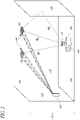
- Figure 1 illustrates an example context or environment in which an object 100 such as a mobile device may be situated.
- the environment 110 in this example includes left wall 120, right wall 130, front wall 135, ceiling 140, and floor or ground 150.
- One or more signal sources 180 generate background wave signals - the aforementioned vector field.
- the mobile device 100 includes a signal detector 170 configured to detect the signals generated by the sources 180 and a dead-reckoning (motion) sensor 190 to report on observed motion.
- a signal detector 170 configured to detect the signals generated by the sources 180 and a dead-reckoning (motion) sensor 190 to report on observed motion.
- motion dead-reckoning
- U.S. Patent No. 7,720,554 discloses, among other things, a low-cost optical sensing system for indoor localization.
- a beacon 160 projects a pair of unique infrared patterns or spots 180 on the ceiling 140.
- the beacon 160 can be placed relatively freely in the environment 110 and adjusted such that it points towards the ceiling 140.
- An optical signal sensor 170 measures the direction to both spots 180 on the ceiling 140.
- the signal sensor 170 then reports the coordinates of both direction vectors projected onto the sensor plane.
- These beacon spots 180 are the signal sources in an example embodiment that is used throughout this disclosure. Other embodiments may use more or fewer spots 180.
- Other wave signals such as those used in Wi-Fi, GPS, cellular networks, magnetic fields, sound waves, radio-frequency identification (RFID), or light can also be used.
- RFID radio-frequency identification
- Corresponding sources include wireless routers, satellites, cell towers, coils, speakers, RFID transmitters, and projectors.
- appropriately configured ceiling lights or speakers may be used in certain embodiments.
- a detector 170 may be configured to take advantage of the distinct Wi-Fi signals available from the various Wi-Fi routers that may be within range.
- existing lights including fixed ceiling lights, may be used with photo-sensitive sensors.
- Other signal sources may generate soundwaves (audible, subsonic, or ultrasonic) and the detector 170 may be configured to detect the generated waves.
- Digital signals including those transmitted by radio and/or as used in wireless communications may also be used.
- a system that tracks the pose of a mobile device 100 equipped with a signal sensor 170 by relying, even in part, on the values reported by that sensor 170 faces a number of challenges.
- the signals sensed by the sensor 170 will have a different strength or value at different locations in the environment.
- the mobile device 100 moves along the ground 150 (although one of skill could readily apply what is disclosed to a mobile device that travels along a wall or ceiling, or that moves (and rotates) in three dimensions).
- One challenge is relating a change in the detected (sensed) signal to a change in ground position.
- the relationship between sensed signal and ground position is the "scale" parameter.
- the orientation of the sensor 170 is fixed relative to the environment 110 and is independent of the rotation of the mobile device 100.
- a gyroscopic or inertial system may be used to rotatably attach the sensor 170 to the mobile device 100 such that when the mobile device turns or rotates, the sensor rotates in a counter direction.
- the sensor 170 is rigidly affixed to or integrated with the mobile device 100 such that its orientation is substantially fixed relative to the orientation of the mobile device 100.
- the position and orientation of the sensor 170 are presumed to be identical to that of the mobile device 100 so that, for example, “sensor 170” is used interchangeably with “device 100” when discussing pose or motion. As discussed below, this assumption simplifies the disclosure. One of reasonable skill can readily account for any fixed or calculable offset between the orientation of the sensor 170 and the device 100.
- rotation of the sensor 170 relative to the environment 110 should not affect the detected signal or should affect it in a way that depends only on the degree of rotation.
- the direction to signal sources 180 changes when rotating the sensor 170, but the magnitude of the signal at that position is not changed.
- some sensors have directional sensitivities.
- a Wi-Fi receiver can show changes in signal strength when the antenna is rotating as a result of the device on which it is mounted (e.g., the mobile device) rotating. Even in such a situation, the variation might be predictable and calculable.
- errors in manufacturing, misalignments in attaching the sensor on the object, uneven flooring, and the like may introduce an additional, difficult to predict, variation in the orientation of the signal sensor 170 relative to the orientation of the device 100.
- a third challenge in determining the pose of a mobile device arises from the multiple paths from the signal sources 180 to the sensor 170.
- a sensor 170 may receive a wave signal not only directly from a source 180 but also through reflections on walls 120, 130, 135 and other stationary and non-stationary objects in the environment (e.g., furniture, trees, and humans).
- the direct path as well as each reflection may contribute to the signal measured on the sensor 170. This can create non-linear and seemingly arbitrary distributions of the signal throughout the environment 110. This effect is referred to herein "multi-path".
- a given signal can be uniquely identified relative to other signals so that when a signal is detected at different times in an environment 110 with multiple signals, a correspondence between the signals can be maintained.
- signals in Wi-Fi, GPS and other networks contain a unique ID as part of their data packet protocol.
- Active beacons such as those disclosed in U.S. Patent No. 7,720,554 , may encode a signature (e.g., by modulating the signal, such as by modulating a light that forms light spots on a ceiling).
- signals are substantially continuous and change over space but optionally not in time. It should be understood that continuity does not mean that there is necessarily a one-to-one correspondence of vector of signal values to ground positions. The same measurement vector might be observed at several different locations in the environment 110 because, for example, of multi-path. Some embodiments may operate with signals that change in time, where the change over time is known or can be predicted.
- FIG. 2 illustrates an example functional block diagram of an embodiment of a localization system.
- a dead reckoning sensor 190 provides relative motion data (odometry). Information from the dead reckoning sensor may be used to estimate, in whole or in part, the device's current position based upon a previously determined position and advancing that position using a known or estimated speed over an elapsed period of time.
- the dead reckoning (motion) sensor 190 may include multiple instances of multiple types of dead reckoning sensors such as those mentioned above.
- a signal sensor 170 provides measurement vectors of the signals in the environment.
- the signal sensor 170 may include multiple instances of one or more types of sensing components.
- the signal sensor 170 may include one or more sensors which detect more than one different types of signals (e.g., the signal sensor 170 may include both Wi-Fi sensors and light sensors).
- Some such embodiments may use only one signal type at a time; some such embodiments may normalize the output of the signal sensor and proceed as if there were only one type of (composite) signal being sensed; and some embodiments may extend what is disclosed below in obvious ways by using the availability of more signal sensor data to improve the filtering results.
- the output of sensors 170, 190 are provided to a Vector Field SLAM module 220.
- the illustrated SLAM module 220 reads and stores information 230 about a grid of nodes.
- the SLAM module 220 also provides pose estimates of the mobile device 100 and map information about the signal distribution in the environment 110. These may be provided to other components for use and/or display. For example, pose estimates may be provided to a navigational component 240, which directs the mobile device 100 to move to a new location based at least in part on its current pose. They may also be provided to an alerting or action system 250 which uses the current pose as at least a partial basis for subsequent action such as cleaning.
- the map may be stored for future use and/or displayed for diagnostic purposes, for example.
- some embodiments will optionally not use GPS, not use WiFi, not use direct light signals (e.g., non-reflected light from lamps or infrared sources), and/or not make use of ceiling lighting fixtures for some or all aspects of the localization process.
- FIG. 3 illustrates example physical components of an appropriately configured example device 100.
- the dead reckoning sensors 190 and signal sensors 170 are instantiated by components such as those described above.
- Those physical sensors may include their own processors and/or local storage components and may be configured to normalize data and generate standardized output signals.
- the sensor components may communicate with one or more processors 310.
- the processor may be, for example, a specially configured chip or a more general processor executing software. Regardless, it is configured in accordance with what is disclosed herein.
- the processor may include its own storage, but it may be advantageous for the device 100 to include additional memory or storage 320 to store any necessary software and the data necessary to implement the methods disclosed below. In some embodiments the sensors may also store data directly in the memory 320.
- ROM read only memory
- flash memory or some other form of persistent storage, although volatile storage may be used as well.
- Data may be stored in volatile (e.g., can be erased when the system powers down) and/or non-volatile memory (which stores the data for later access even if the device is powered down and then powered up again).
- the processor 310 and storage 320 may also be used for functional purposes not directly related to localization. For example, the mobile device 100 may use them when performing navigation or when performing tasks such as cleaning or guarding. In other embodiments, the processing and storage capacity are dedicated to localization and mapping and the device contains additional computational capacity for other tasks.
- the processor 310 may be operatively connected to various output mechanisms such as screens or displays, light and sound systems, and data output devices (e.g., busses, ports, and wireless or wired network connections).
- the processor may be configured to perform navigational routines which take into account the results of the SLAM process. Executing a navigational process may result in signals being sent to various controllers such as motors (including drive motors or servomotors), brakes, actuators, etc, which may cause the mobile device 100 to move to a new pose (or to perform another activity, such as a cleaning function). The move to this new pose may, in turn, trigger additional output from the sensors to the processor, causing the cycle to continue.
- various controllers such as motors (including drive motors or servomotors), brakes, actuators, etc, which may cause the mobile device 100 to move to a new pose (or to perform another activity, such as a cleaning function).
- the move to this new pose may, in turn, trigger additional output from the sensors to the processor, causing the
- An example embodiment is configured with an ARM7 processor, 256K of flash ROM for software, and 64K of RAM for data. These are not minimum requirements - some or all of what is disclosed herein can be accomplished with less processing and storage capacity. Other embodiments may be different processors and different memory configurations, with larger or smaller amounts of memory.
- the signal sensor 170 measures bearing and elevation to two or more of the projected spots 180 on the ceiling 140.
- Bearing and elevation can be translated into (x, y) coordinates in a sensor coordinate system by projecting them onto the sensor plane, which in the illustrated example embodiment is typically less than 10cm above the ground 150 and is substantially parallel to it.
- the amount of light from each spot 180 is measured as the signal magnitude.
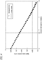
- the geometry of the illustrated localization system results in a linear model for position estimation in an ideal environment without multi-path signals. That is, if the sensor 170 moves one meter in one direction, the sensor coordinates change by a certain amount (depending on the scale parameter, which is proportional to the height of the ceiling 140). If the sensor 170 then moves another meter into the same direction, the sensed signals change by the same amount.
- Figure 4 illustrates this property by using measurements of a sensor 170 mounted on a fixed path (or "rail") along which the sensor 170 moves in a fixed and known direction.
- the rail is an experimental platform for evaluating the systems and methods described herein which allows the ground position of the sensor 170 to be known to observers and which also allows the orientation of the sensor 170 to be controlled.
- On the x-axis the position on the rail is shown.
- the y-axis shows the y coordinate of one of the spots 180 in sensor units.
- the linear distribution of the wave signal can be used directly for the localization of the sensor 170 in conjunction with other system parameters.
- ⁇ init s 1 s 2 m 0
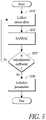
- FIG. 5 A flow chart for computing the parameters of this linear model (either Eq. 2 or Eq. 3) is shown in Figure 5 .
- sensor measurements are obtained from the signal sensor 170.
- data about the concurrent pose of the device 100 is also obtained (e.g., at the same or substantially the same time), such as from one or more on-board dead-reckoning sensors 190 or from separate monitoring systems.
- State 510 continues while the device 100 travels a short distance.
- a RANSAC method (or, more generally, any algorithm for fitting data into a linear model) is run.
- the status of the process is evaluated.
- an embodiment may determine the initialization is sufficient. If so, then at state 530, the output of RANSAC is used to initialize the parameters for the relevant equation. If not, the initialization process continues.
- RANSAC Random Sample Consensus
- RANSAC Random Sample Consensus
- the RANSAC algorithm runs several iterations. In a given iteration a number of measurements are chosen at random (the term "random" as used herein, encompasses pseudo random). In an embodiment using two spots 180, two signal sensor 170 readings each containing measurements to both spots 180 are sufficient.
- the parameter values are determined by solving the set of equations arising from placing the chosen measurements into the mathematical model, Eq. 2. More generally, Eq. 3 may be used.
- the computed parameters are then evaluated using some or all available sensor data, optionally including dead reckoning data. This usually computes a score such as the number of inliers or the overall residual error. After completing the desired number of iterations, the parameter values with a score meeting certain criteria (e.g., the best score) are chosen as the final parameters.
- Embodiments may use variations of RANSAC or alternatives to it.
- one or more algorithms for accounting for noisy sensors and dead-reckoning drift can be used to implement a system to effectively track the pose of the mobile device 100 with more accuracy, in less time, and/or with lower computational resource requirements than many conventional methods.
- examples of such algorithms include the Kalman Filter, the Extended Kalman Filter (EKF), the Invariant Extended Kalman Filter (IEKF), and the Unscented Kalman Filter (UKF).
- EKF Extended Kalman Filter
- IEEEKF Invariant Extended Kalman Filter
- UDF Unscented Kalman Filter
- the ability of these filters to effectively track pose after the initialization process of Figure 500 tends to degrade in environments where the distribution of the wave signal is non-linear. But even in environments, such as room 110, where the wave signal is distorted (e.g., by multi-path), the linear model described here is still useful for the initialization of non-linear systems according to what is disclosed herein.
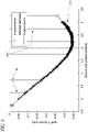
- multi-path occurs when the wave signal not only reaches the signal sensor 170 directly but also in other ways, such as by reflecting from nearby objects or walls (e.g. the right wall 130 in Figure 1 ). As the sensor 170 moves closer to wall 130, due to occlusion and limited field of view, the sensor 170 receives more signal contributions from wall reflections. The result is a shift in the signal back to a position that appears to be further away from the wall 130.
- Figure 6 illustrates this scenario where right wall 130 reflects the signal from the spots 180. Note how the curve 610 bends over and switches to the opposite direction: when the mobile device 100 is 3 meters from its starting point the sensor 170 is reporting a detected value of approximately -0.3, the same value it reported at approximately 1.5 meters, instead of the expected value of approximately -0.55 predicted by a linear model.
- This compression of the sensor signal appears with any wave signal that shows reflections from walls or other objects. It makes position estimation particularly difficult because a range of signal sensor readings do not match to exactly one ground position but instead have a least two ground position candidates. Even more candidates are possible when taking measurements in 2D or higher dimensions, or when the multipath pattern involves multiple objects, for example.
- signal strength measurements can still be used for localization in a multi-path environment via, for example, a Bayesian localization framework such as an EKF.
- a piece-wise linear approximation (pieces are illustrated in Figure 6 by the solid vertical lines 620) is used to substantially simultaneously learn the signal shape or "map" (the strength of the signal throughout the environment) and estimate the pose of the mobile device 100. This is done using a simultaneous localization and mapping (SLAM) approach.
- SLAM simultaneous localization and mapping
- the second challenge mentioned was rotational variability.
- the measurements of the observed vector signal can change.
- This is the rotational variability of the sensor 170.
- a sensor 170 in an embodiment using spots 180 outputs (x y) coordinates of the center of a spot 180 on the sensor plane.
- the (x y) coordinates essentially are a vector representing bearing and elevation to the spot 180.
- the bearing should change - the elevation should stay constant.
- elevation changes (usually, but not always, by a relatively small amount) due to variations in manufacturing, calibration errors, or misalignments in mounting the sensor 170 on the mobile device 100.
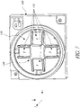
- Figure 7 shows a top-down perspective of an example of one embodiment of a signal sensor 170 mounted on a mobile device 100.
- Figure 1 represents the sensor 170 as protruding from the mobile device 100
- Figure 7 depicts an embodiment in which the sensor 170 is recessed in a cavity or depression with a substantially circular perimeter (although other perimeters could also be used).
- the sensor 170 comprises four infrared photodiodes 710 mounted on a pyramidal structure 720.
- the top of the pyramid 720 does not contain a photodiode 710 and is substantially coplanar with the top surface of the mobile device 100.
- the sensor 170 may have a different structure including, for example, more or fewer photodiodes 710 arranged in a similar or different configuration.
- each of the photodiodes 710 measures incoming light by producing an electric current substantially proportional to the received light.
- Each of the two opposing photodiode pairs is then used for measuring the direction of light on the corresponding axis.
- the computation of the light direction and the effects of rotational variability for the x axis of the sensor are discussed.
- the computations for the y axis are analogous.
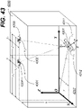
- Figure 8 illustrates a representation 800 of the sensor 170 of Figure 7 , simplified for the purposes of clarity. Only the pair of photodiodes 710 measuring along the x axis is shown. Light from one of the spots 180 (it can be assumed to be spot 181 without any loss of generality) is directed at the sensor 170 as illustrated by light vectors 810. The x coordinate reported by the sensor 170 is proportional to the tangent of the elevation angle ( ⁇ ) to spot 181. This tangent of ⁇ is measured through the two currents i1 and i2 of the opposing photodiodes 801 and 802, respectively.
- the angle ⁇ of the pyramid is a parameter that may vary among embodiments. Some embodiments may have an adjustable angle ⁇ .
- ⁇ is greater than zero or that such an effect is simulated (e.g., through the use of apertures above the photodiodes which cast shadows and limit the exposure of the photodiodes to light from the spots.).
- any effective angle ⁇ between 0 and 90 degrees may be used, it is preferably within the range of 15 to 75 degrees. Some embodiments may use, for example, 30, 45, or 60 degrees.
- the rotational variability is modeled by an offset in ⁇ that changes with the orientation of the sensor 170 such that Eq. 5 holds, where ⁇ ' is the angle to the ideal axis of rotation perpendicular to the ground plane and ⁇ ⁇ is the angular error that changes with rotation.
- ⁇ ⁇ ′ + ⁇ ⁇
- the parameters for rotational variability are substantially independent of where the spots 180 are located. All spots 180 may therefore share substantially the same parameters.
- Rotational variability is not limited to the illustrated embodiment.
- Other sensor(s) 170 that measures bearing-to-signal sources 180 can show similar effects when the vertical axis of the sensor 170 is slightly misaligned or the sensor 170 otherwise rotates around an axis different from the ideal one.
- antennas for radio or other wireless communication can show slight changes in the received signal when they rotate.
- an optional useful model of the way the vector of signal values changes on rotation of the sensor 170 is a function that only depends on the orientation of signal sensor 170 and parameters describing the rotational variability of the signal sensor 170.
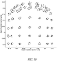
- Figures 9 and 10 illustrate rotational variability and non-linearity arising from multi-path signals.
- the two figures depict the environment of room 110 from a top down perspective.
- Figure 9 shows a regular grid 900 consisting of 8 x 7 positions (every 50 cm in this example) on the floor 150.
- a system using spots 180 was deployed with an appropriately configured signal sensor 170.
- sensor measurements were taken with eight different sensor orientations (every 45°).
- FIG. 10 shows the resulting signal measurements using different symbols for the eight orientations.
- the measurements form a ring which shows the rotational variability at this location.
- the error caused by rotational variability can be constant (as in this example) but might also change over time or location, e.g., if the angular error ⁇ ⁇ is more significant or if there are other similarly variable sources of error, such as uneven floors or motion dependent device vibration, not modeled in Eq. 4 to Eq. 9.
- Changes in the pitch or angle of the mobile device relative to the surface it is traversing can also cause or contribute to rotational variability.
- uneven floors or ground such as might result from rolling terrain, general bumpiness, twigs or branches, brickwork, and the like can cause the pitch of the mobile device to change.
- rotational variability due to change in pitch is monotonic, although it complements rotational variability due to manufacturing and other sources
- At least some rotational variability due to changes in pitch may be accounted for using the methods described herein. For example, changes in pitch of less than 3, 5, or 7 degrees (or other pitches) may be accommodated by some embodiments without modification to what is disclosed herein.
- Figure 9 also shows the effect of multi-path signals.
- the walls on the left 120, right 130, and front 135 cause signal reflections. While the left wall 120 and right wall 130 create some level of signal compression, the front wall 135 causes severe reflections that make the signal bend over. Even worse, in the corners of the room, the signal is reflected from two walls and therefore the resulting measurement is even more distorted.
- localization of a mobile device 100 equipped with a signal sensor 170 is performed by learning the signal distribution in the environment 110 while at the same time (or at substantially the same time) localizing the mobile device 100.
- This is known as simultaneous localization and mapping (SLAM).
- SLAM simultaneous localization and mapping
- SE(2) is the space of poses in the 2 dimensional plane and R M the space of the map features.
- x 0 (0, 0, 0) T .
- the system receives a motion input u t (e.g., odometry from dead reckoning sensors 190) with covariance R t and a measurement z t (e.g., of signal strength from signal sensors 170) with covariance Qt.
- a motion input u t e.g., odometry from dead reckoning sensors 190
- a measurement z t e.g., of signal strength from signal sensors 170
- the motion input u t is measured, for example, by motion sensors 190 on the mobile device 100 and describes the change in pose of the sensor 170 from time step t - 1 to t.
- the motion input may be provided by external sensors or a combination of internal and external sensors.
- the input vector u t is associated with a covariance R t that models the accuracy of the pose change.
- Typical motion sensors 190 include wheel encoders, gyroscopes, accelerometers, IMUs and other dead-reckoning systems.
- the SLAM system uses a sensor model to predict the observation.
- the sensor reading z t is associated with a covariance Q t modeling the accuracy of the measurement.
- the sensor model is defined by a function h that predicts an observation given the sensor 170 pose at time step t and map features as in Eq. 13, where e z is a zero mean error with covariance Q t .
- the sensor model h depends on the map features and the available signal sensor 170 in the mobile device 100. In early SLAM applications such as those described in Thrun et al.
- map features are landmarks and the sensor model h computes bearing and distance to them.
- the systems and methods disclosed herein optionally use a very different approach: some or all of the features are signal values at predetermined or fixed locations and, few or none of the features are landmarks in the environment.
- SLAM SLAM it is possible to include in the sensor model calibration parameters like those describing rotational variability of the sensor 170.
- the SLAM algorithm then not only estimates device pose and map features, but also estimates the calibration parameters. All calibration parameters are summarized in a vector c. The size of this vector depends on the sensor 170.
- the calibration parameters include the two bias constants ( c x , c y ) in Eq. 10.
- Embodiments also learn the vector field generated by M signals over the environment.
- This vector field can mathematically be described as a function that maps a ground pose to a vector of M signal values.
- VF SE 2 ⁇ R M
- the space of poses SE(2) can be decomposed into position and orientation.
- Each node i holds a vector m i ⁇ R M describing the expected signal values when placing the sensor at b i and pointing at a pre-defined direction ⁇ 0 .
- the spacing of cells in the regular grid defines the granularity and precision with which the wave-signal distribution in the environment 110 is modeled.
- a finer spacing leads to more cells, yielding better precision but requiring more memory.
- a coarser spacing results in fewer cells, requiring less memory but at the possible cost of precision.
- the exact parameter for the cell size depends on the environment, mobile device, and the application. For the purpose of covering an environment 110 with reasonable precision (e.g., for systematic floor cleaning), the cell size could be 0.5 m to 2 meters for a system using spots of frequency modulated light as signal sources 180 in an environment with a ceiling height of 2.5 to 5 meters.
- the expected signal values are computed by bilinear interpolation from the nodes of a cell (e.g., the four nodes) containing the sensor position.
- a cell e.g., the four nodes
- the four nodes may be determined from the sensor position at time t and node positions b i .
- "Current cell” refers to the cell in which the sensor is positioned at the current time step t.
- the expected signal values at (x, y) with orientation ⁇ 0 are then computed as Eq. 16, where m i 0 , m i 1 , m i 2 and m i 3 are the signal values at the four cell nodes and w 0 , w 1 , w 2 and w 3 are the weights of the bilinear interpolation computed as Eq. 17.
- h R is a continuous function that transforms the interpolated signal values obtained through Eq. 16 by the sensor orientation and rotational variability. This is usually a rotation by orientation ⁇ followed by a correction with the rotational variability c.
- the rotational component h R therefore becomes Eq. 19, where ( h x 1 , h y 1 , h x 2 , h y 2 ) is the output vector of Eq. 16. It is also possible to formulate the equations for a variable number of spots 180 since the components in Eq. 16 to Eq. 19 are not correlated between spots 180. Similar equations can be readily obtained for other signal sources.
- the function in Eq. 16 is evaluated for the current and several neighboring cells and then a weighted mean of them is computed as the final result.
- the weights are taken as the mass of probability of the current position estimate that falls into each cell.
- the weight of a given cell is a function of the probability that the sensor or mobile device is within this cell. This probability can be derived from the current mobile device pose and associated uncertainty as it is computed by the localization filter.
- the complete trajectory of the device 100, rotational variability of the sensor 170, and/or some or all map features are computed.
- GraphSLAM One algorithm that computes an estimate of Y is GraphSLAM, which is used in some embodiments and is described in more detail below.
- Embodiments may use any of the described full SLAM or on-line SLAM algorithms, as well as other algorithms. Some embodiments can be configured to use a particular SLAM algorithm depending on, for example, a user's preference, the computational resources available, and other operational constraints.
- GraphSLAM is a non-linear optimization method for estimating the state vector in Eq. 20 by finding the values in Y that best explain the sensor and motion data from sensors 170 and 190.
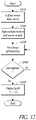
- FIG. 12 An example implementation of GraphSLAM is illustrated in Figure 12 .
- One general approach is to first provide an initial estimate of the state vector Y at state 1210. This may be based on, for example, data from the dead reckoning sensors 190 or data from the signal sensors 170. Then the embodiment approximates motion model g(.) and sensor model h(.) by linear models using Taylor expansion at the current estimate of the state vector at state 1220. This results in a quadratic function of Eq. 22. The linear equation system that reduces or minimizes the quadratic function obtained in state 1220 is solved or optimized at state 1230. This provides an improved estimate of Y. The second and third states are repeated until the solution converges to a desired degree at state 1240. If sufficient convergence is not obtained, then optimization state 1230 is repeated. If it is obtained, then at state 1250 a path is output.
- the linear equation system may optionally be solved during optimization state 1230 using Conjugate Gradient, since the system is usually sparse and positive definite.
- the initial node values m i are computed from Eq. 1 and Eq. 2. For example, the parameters in Eq. 1 are computed by applying RANSAC over a short initial sequence, as discussed above. The node values m i are then obtained from the node position b i through Eq. 2.
- the short initial sequence typically contains a minimum or relatively low number of sensor samples (e.g., 2 to 50) while the mobile device 100 moves a certain distance.
- This distance is usually proportional to the chosen cell size such that enough samples are available that cover a reasonable fraction of the cell.
- the distance threshold may be selected within the range of 0.5 m to 1 meter. More generally, some embodiments may be configured to travel a distance of 1/3 to 2/3 of the cell size. This distance may also depend on the size of the mobile device 100: typically, larger mobile devices should travel further during the initialization phase.
- a given sample is spaced a minimum distance from an adjacent sample. This distance may be determined based on a dynamically configured initialization travel distance and sample count, for example. It may also be fixed a priori so that samples are taken after every half second of travel or after every 10 centimeters of travel, for example, although other time periods and distances may be used.
- GraphSLAM may be implemented as a batch method since the motion and sensor data needs to be available when computing the non-linear optimization. Furthermore, the amount of computation is significant. These constraints may make it difficult to use GraphSLAM in certain embedded systems with limited computational resources, such as if the mobile device 100 is a conventional vacuum cleaner or other consumer product. GraphSLAM is nevertheless useful as a baseline algorithm for computing the best possible result given the sensor data and a chosen model. For example, it can be used during the development of products or selectively run when computational resources are available to check the performance of other methods. Further, there are certain embodiments of product mobile devices where there are sufficient computational and memory resources to utilize GraphSLAM.
- EKF Extended Kalman Filter
- KF Kalman Filter
- EKF-SLAM is an on-line SLAM method.
- the state vector contains the current pose of the device 100 but not older or future poses (or estimates thereof). Furthermore, the size of the state grows as the mobile device 100 moves in the environment 110. Initially the state contains only device pose, rotational variability and the node estimates of the 4 nodes of the initial cell.
- y 0 x 0 c m 1 m 2 m 3 m 4
- the EKF computes an estimate of this state by maintaining mean and covariance modeling a Gaussian distribution over the state.
- the initial mean is set to Eq. 26, where ⁇ is a rough guess/estimate of the rotational variability of the sensor 170 and m ⁇ 1 ... m ⁇ 4 are initial values of the four nodes obtained from sensor data of a short initial sequence as described before using Eq. 1 and Eq. 2.
- ⁇ 0 x 0 c ⁇ m ⁇ 1 m ⁇ 2 m ⁇ 3 m ⁇ 4
- the initial covariance is a diagonal matrix where the vehicle uncertainty is set to 0 and the uncertainties of rotational variability and the four initial nodes are infinite.
- ⁇ can be replaced by a large number.
- EKF-SLAM updates the state as Eq. 28 and Eq. 29, where ⁇ extends the motion model g over all state variables and F y is its Jacobian with respect to state per Eq. 30 to Eq. 31.
- F y ⁇ ⁇ ⁇ y ⁇ t ⁇ 1 u t
- the system determines the current cell, i.e. the cell in which the mean estimate of current device pose x ⁇ t falls, and then updates the mean and covariance of the state.
- the current cell at time t can be:
- nodes not yet present in the state vector need to be added by augmenting the state with the new nodes.
- adding a node to the state vector containing n nodes is achieved by Eq. 32 and Eq. 33, where m ⁇ n +1 and M n+1 are the mean and covariance of the new node. This mean and covariance can be computed from nodes already contained in the state vector by linear extrapolation per Eq. 34 and Eq.
- M is the covariance over all nodes
- S is additional noise for inflating the new covariance to allow the new node to vary for accommodating the non-linear structure of the wave signal.
- the vector field changes slowly over space (i.e., the signal is relatively constant).
- change between adjacent nodes is limited and extrapolation might degenerate into a linear model.
- Some embodiments use a smaller S in introduced in such circumstances, and some embodiments use introduced a larger S if the vector field is known or predicted to change more rapidly over space.
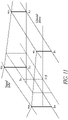
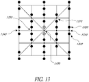
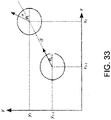
- a new node 1330 is initialized by taking into account the 8-neighborhood directions around the new node 1330, as illustrated in Figure 13 .
- the two neighbors on the straight line from the new node 1330 are used to extrapolate the mean and covariance of the new node.
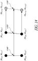
- the new node can be computed as shown in Figure 14 .
- the mean and covariance are computed from node j 1 1340 and j 2 1350 only. Both nodes contain the mean estimates of both sensor spots.
- the extrapolation is such that the mid point between the spots 180 is used for extrapolation.
- the orientation of the line between the two new spot estimates is taken over from the closer one. This has the effect that changes in orientation are not propagated when initializing new nodes.
- Some embodiments optionally only consider cases where a new node can be initialized from a pair of the 8 directions. In case there are several possible candidates, an embodiment may chose the one with the smallest resulting covariance M n . For comparing covariances, the matrix determinant, the trace of the matrix, its Frobenius norm, or other norms can be used.
- some embodiments discard the sensor observation. Such a situation may occur, for example, when the mobile device 100 travels over a full cell without any sensor 170 observations and then arrives in a cell where all four cells are not yet part of the state vector (scenario 3, above). In this scenario, the utility of the new observation for localization may be minimal. Nonetheless, some embodiments may still initialize a new node by linear combinations of other nodes in the state vector using Eq. 34 and Eq. 35. Some embodiments may optionally only use the motion updates (e.g., the odometry from the dead reckoning sensors 190) of the mobile device 100 and wait until the device 100 returns to an existing cell or to a cell that can be initialized. Another approach is to start over and re-initialize the system from the current pose.
- the motion updates e.g., the odometry from the dead reckoning sensors 190
- h ( y t ) is the sensor model defined in Eq. 18, H y the Jacobian of the sensor model and K the Kalman gain.
- FIG. 15 A flow chart of the EKF-SLAM method for object localization is shown in Figure 15 .
- the initial parameters are set per Eq. 26 and Eq. 27.
- a motion update such as from the dead reckoning sensors 190 then it is applied at state 1530 per Eq. 28 and Eq. 29.
- a value from the signal sensor 170 and if a new cell is needed, it is initialized at state 1540 per Eq. 32 to Eq. 36.
- a sensor update is performed at state 1550 per Eq. 37 and Eq. 38.
- a new pose is output at state 1560 and the process continues with the next time period.
- EKF-SLAM has the advantage that it is an on-line method, integrating motion/odometry and signal sensor measurements as they appear.
- the most computationally expensive operation is the update of the covariance matrix on sensor update in Eq. 38, state 1550. This involves the update of large numbers (e.g., all) of the matrix elements, an operation that takes time quadratic in the number of nodes in the state.
- the covariance ⁇ t is fully correlated. That is, there are few, if any, elements that are zero. This typically requires holding the full matrix in a data memory, which may limit the applicability of the method for embedded systems or other environments if there are overly limited memory resources.
- An additional step in the EKF as well as in other filters is outlier rejection.
- the filter rejects these measurements. This may be accomplished by not updating the filter on such measurements, which may be the result of hardware errors, signal interference, or irregular timing problems, for example.
- the sensor measurement itself can be examined for valid data.
- a threshold on the absolute magnitude of the signal strength reported by a sensor if the range of allowable magnitudes for the signal being detected is known. If the measurement falls below or above this threshold it is rejected.
- Another way to detect outliers is by comparing the received measurement z t with the expected one h ( ⁇ t ) . If the difference (e.g., as reported by means of the Mahanalobis distance, which is based on correlations between variables via which different patterns can be identified and analyzed) is too large, the measurement is rejected.
- EIF Extended Information Filter
- the EIF is similar to the Extended Kalman Filter in that it models a Gaussian distribution over the state space and processes motion and signal sensor data on-line.
- Its parameterization often called a dual representation, differs from that used by EKF.
- the EIF-SLAM algorithm processes data from the motion sensors 190 and signal sensors 170 in the same way as EKF-SLAM described above.
- the computation of information vector and information matrix on object motion and sensor measurement can be derived from Eq. 26 to Eq. 40 by inserting Eq. 41 and simplifying the resulting equations.
- EIF-SLAM In general a direct application of the EIF-SLAM algorithm does not provide a greater advantage than EKF-SLAM. Under some approximations, however, it is possible to keep the information matrix sparse, i.e. many elements are zero, allowing for a more compact storage and more efficient updates in terms of time and computational resources.
- EIF-SLAM has the property that when inserting a signal sensor 170 measurement, only those elements in the state the measurement depends on need to be updated in the information matrix.
- the update on device motion causes a full update of the whole information matrix in the general case. This causes the information matrix to become non-zero in most if not all elements, which may destroy any sparsity that was present before the motion update.
- Some embodiments may use strategies for approximating the update of the information matrix on device motion that preserve the sparsity of the information matrix. Two such methods are the Sparse Extended Information Filter (SEIF) and the Exactly Sparse Extended Information Filter (ESEIF).
- SEIF Sparse Extended Information Filter
- ESEIF Exactly Sparse Extended Information Filter
- ESEIF Yet another approach available to some embodiments for state estimation is ESEIF.
- features refer to landmarks.
- the features are the nodes.
- the active features are a subset of all features. Typically those features that are currently observed by the mobile device 100 are the active ones. Other features are called "passive”.
- ESEIF-SLAM conceptually integrates out the device pose and then re-localizes the device 100 using observations from only those features (nodes) that should stay or become active. By integrating out the device pose, the state becomes free of the pose. Any uncertainty in the device pose is moved into the feature estimates through the cross-information between device pose and feature. When re-localizing the device 100, only the features used in the signal sensor 170 observation then establish non-zero cross information. This way the sparseness of the information matrix is preserved.
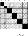
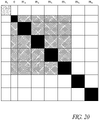
- Figures 16 - 22 show information matrices supporting this description. Initially the system starts with 4 nodes, as in Eq. 23. The corresponding information matrix is shown in Figure 16 . Only the diagonal blocks in the information matrix contain information and are non-zero, as indicated by black solid squares. All other entries are zero (shown as white). The diagonal blocks refer to the device pose x t , the rotational variability c and the initial 4 nodes m 1 ... m 4 .
- the system updates the complete information matrix using all 4 nodes as active features. Eventually the matrix becomes fully dense (most if not all elements become non-zero), as illustrated in Figure 17 .
- the procedure of integrating out the device pose, initializing new nodes, and re-localizing the device takes place.
- the uncertainty of the device pose is integrated out. This moves information from the object pose into the rotational variability and the 4 nodes through their cross information.
- the result is an information matrix as shown in Figure 18 , which usually contains stronger information between nodes than before and lacks a device pose.
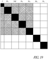
- new nodes are initialized and added to the state.
- two new nodes m 5 and m 6 may be added as shown in Figure 19 . This indicates that the device 100 moved into a neighboring cell sharing nodes m 3 and m 4 with the initial one.
- the processing necessary for the addition of these nodes is described below. Note that the description also applies for other situations where 1, 3, or 4 new nodes need to be added, or, in embodiments that use cells with greater than four nodes, more than four new nodes need to be added.
- the initial values for the information vector and matrix are obtained similarly to Eq. 32 to Eq. 36, but in the information form as set out in Eq. 41.
- the new information matrix then becomes the one as shown in Figure 19 . Note that there is no cross information between the new nodes and other entries in the state.
- the pose of the device 100 is then reintroduced.
- an object is localized through observations of active features.
- Vector Field SLAM algorithm this is performed in two steps. First, the state is augmented with the new device pose as shown in Figure 19 .
- the entries for the new device pose in information vector and matrix are computed using Eq. 41 and the following mean and covariance per Eq. 42 and Eq. 43, where R 0 is a parameter that increases the uncertainty of the new device pose.
- R 0 is a parameter that increases the uncertainty of the new device pose.
- the new device pose stays unchanged but becomes less certain.
- the device 100 moves within the current cell, in this example embodiment optionally only the device pose, rotational variability, and active cells m 3 ... m 6 are updated, as was noted during the discussion of the initial situation.
- the state is extended and the information vector and matrix are augmented with new nodes as described above. If the new cell has been visited before, no new nodes need to be added to the state. In either case, the same procedure of integrating out device pose followed by re-localization takes place.
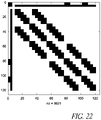
- Figure 22 shows the information matrix after a longer run of the system configured as described.
- the state contains a total of 29 nodes.
- the device pose contains cross information to the currently active nodes only (around rows 80 and 110).
- rotational variability contains cross information to all nodes.
- the nodes themselves have cross-information to spatially neighboring cells, which are at most eight neighbors per node.
- the mathematical equations for motion update e.g., from the dead reckoning motion sensors 190
- signal sensor update e.g., from the sensors 170
- sparsification can be formulated directly in the information space, i.e. only using ⁇ and A for storing the state between motion and sensor updates.
- an estimate of the mean ⁇ is needed for computing the Jacobians of motion and sensor model.
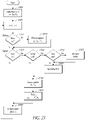
- FIG. 23 A flow chart of an example implementation of the ESEIF-SLAM algorithm for object localization is shown in Figure 23 . It is similar to the EKF-SLAM algorithm, with an initialization state 2300, a motion update state 2310 if there is new motion (odometry) data, a signal update state 2340 if there is new signal sensor data, preceded by a new-node initialization state 2320 if new nodes are added, but also with an additional sparsification state 2330 that integrates out device pose and re-localizes the device 100 when changing to another cell. Also, there is another state 2350 for recovering the current mean ⁇ t from the information space by solving an equation system. After the solving state 2350, a new device pose is produced at state 2360 and the process repeats.
- This flow chart like those illustrating the other algorithms, is illustrative. One of ordinary skill will make use of available optimizations when implementing an algorithm, including these algorithms.
- the state vector as defined in Eq. 20 and Eq. 21 only contains one field for rotational variability. This is under the assumption that rotational variability does not change with location and thus can be shared among all nodes. There are, however, situations where this is not the case, e.g. when the error ⁇ ⁇ in Eq. 5 is significant and the approximations in Eq. 7 to Eq. 9 introduce a larger error, or when the sensor 170 is tilted due to uneven floor. There are different ways to deal with changing rotational variability.
- each node contains its own estimate of rotational variability.
- the state vector of full SLAM in Eq. 20 containing the full object path changes into Eq. 44, with similar changes for the state of on-line SLAM in Eq. 21.
- y x 1 ⁇ x T m 1 c 1 ⁇ m N c N
- the rotational variability is computed similar to the expected node values by using bilinear interpolation per Eq. 45, where c i 0 , c i 1 , c i 2 and c i 3 are the rotational variability estimates at the four cell nodes according to Figure 11 and wo, w 1 , w 2 and w 3 are the weights from Eq. 17.
- c w 0 c i 0 + w 1 c i 1 + w 2 c i 2 + w 3 c i 3
- V t 0 as long as the device 100 stays within a cell and V t is set to a diagonal matrix with constant non-zero values on the diagonal only when the device 100 changes between cells.
- V t is used to allow a change in rotational variability when moving between cells in the ESEIF-SLAM system.
- the rotational variability is integrated out and re-localized as the device pose is. This is done because adding V t in the information space would otherwise fully populate the information matrix, destroying or reducing its sparseness.
- the states for sparsification with rotational variability included are analogous to the previously described method.
- An additional advantage of this approach is the removal of cross-information between rotational variability and passive nodes. This further reduces memory requirements and saves computations, at least partially counteracting the additional computation necessary to perform the calculations.
- These methods and systems may also be used for detecting and estimating "drift" on, for example, carpet.
- the carpet When a mobile device 100 moves on a carpeted surface, the carpet exhibits a force onto the mobile device 100 tending to slide or shift the mobile device 100 in a certain direction. This effect is caused by the directional grain, material, or other properties of the carpet. Other surfaces, such as lawns or artificial turf, may also exhibit similar properties.
- the amount of this drift can be estimated by the localization filter in different ways.
- the filter state in Eq. 24 is augmented by two additional variables drift x and drift y that represent the amount of carpet drift in the x and y direction of the global coordinate frame.
- the motion model in Eq. 11 then takes into account these new parameters and the filter estimates their values at the same time it estimates the other state variables.
- the mobile device 100 may be configured to move a certain distance forward followed by the same distance backward. From the difference in the position output of the localization system at the beginning and end of this sequence, the amount of carpet drift can be estimated because the carpet drift may be proportional to this position difference. Typically, such a distance would be small enough that it can be traversed rapidly but large enough that an appreciable difference can be detected and the results not obfuscated by noise. Some embodiments may use distances in the range of 10 cm to 2 meters. Some embodiments may use smaller distances. Some embodiments may use larger distances.
- FIG. 10 shows the position of the sensor 170 directly determined by a linear sensor model in this environment.
- the compression on the left, right and top end is significant: a system using this linear model would loose significant accuracy in pose estimation.
- the simulated relative pose data and the resulting odometry path are plausible examples of internal motion estimates.
- Mobile devices such as autonomous vacuum cleaners or other consumer products can show a similar degradation of pose estimation when using the integration of wheel encoder counts as the only method for pose estimation for example.
- the accuracy of the individual Vector Field SLAM implementations was compared to ground truth. In general, all three methods provide higher accuracy than other methods that only use linear sensor models.
- the GraphSLAM method usually provided slightly better accuracy than EKF-SLAM and ESEIF-SLAM. The latter two usually provided similar accuracy.
- the absolute position error was determined to depend on several factors such as ceiling height and the size of environments. In the test environment, the overall mean position error was about 6 cm.
- the sources of error may vary depending on the signal sources 180 used. For example, ceiling height may not be a significant contributor to error if the background signal used is generated by magnetic coils suspended over the operating environment.
- Vector Field SLAM also provides information about the learned sensor model or map - the signal strength through the environment.
- Figures 26 and 27 show the learned coordinates for a signal source, in this example an infrared pattern 801 (the plots for a second infrared pattern or spot 802 are similar and omitted). Error bars indicate the 2 sigma levels of the mean values at each node position. One can see how the sensor signal is bent towards the rear wall 135. This shape is accounted for by the piece-wise approximation of the sensor signal.
- a typical embodiment will run asynchronously in that a new time step is considered to occur whenever new data is available from signal sensor 170. This may be as often as six or seven times a second. In some embodiments, new sensor data may be ignored if the embodiment is still integrating previously available data and generating new pose information. In some embodiments the localization processer may request data from the signal sensor 170 or otherwise indicate that it is available to process that data. Some embodiments may run synchronously, with new data provided at fixed and regular time intervals.
- the systems and methods disclosed herein can be implemented in hardware, software, firmware, or a combination thereof.
- Software can include compute readable instructions stored in memory (e.g., non-transitory memory, such as solid state memory (e.g., ROM, EEPROM, FLASH, RAM), optical memory (e.g., a CD, DVD, Bluray disc, etc.), magnetic memory (e.g., a hard disc drive), etc., configured to implement the algorithms on a general purpose computer, special purpose processors, or combinations thereof.
- memory e.g., non-transitory memory, such as solid state memory (e.g., ROM, EEPROM, FLASH, RAM), optical memory (e.g., a CD, DVD, Bluray disc, etc.), magnetic memory (e.g., a hard disc drive), etc., configured to implement the algorithms on a general purpose computer, special purpose processors, or combinations thereof.
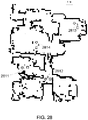
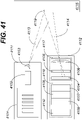
- Figure 28 shows a typical home environment.
- Four navigation cubes each projecting two patterns onto the ceiling, each one of them referred to as Northstar beacons 2811, 2812, 2813, 2814, allow the robot to navigate through virtually the entire home.
- the Northstar spots are projected onto the ceiling and are indicated by star and square icons. Obstacles identified by the robot are drawn in black. Units are in meters.
- a dead reckoning technique can be used to estimate motion and/or positioning.
- the robot estimates relative motion by using both wheelodometry and a gyroscope so that it is able to move out of areas covered by beacons for extended periods of time.
- the gyroscope can correspond to a MEMS gyroscope. In one embodiment, only a gyroscope with yaw is used.
- the system should be able to resume treatment, such as cleaning, after these events.
- Treatment can include, but is not limited to, cleaning, wiping, sweeping, vacuuming, painting, spraying, planting, or the like.
- a tracking approach is formulated that allows the robot to reposition itself in a previously mapped area when operation is resumed.
- the robot is localized by searching the vector field for positions that provide a signal vector similar to a measurement taken by the robot. As the vector field does not need to be bijective, the measurement may fit to multiple places. Each such position is considered as a hypothesis, and is successively tracked over some distance to confirm its correctness.
- continuous signals include the received signal strengths of WiFi base stations or the signals measured from active beacons. The particular physical characteristics of the signals do not matter as long as the continuous signals can be uniquely identified, are relatively stationary over time and change, preferably continuously, over space. In one embodiment, the coordinates of two spots projected onto the ceiling are used as the continuous signals. It will be understood that these continuous signals can be bursty or pulsed, such as provided by flashing infrared LEDs.
- the robot moves through a time series of poses x 0 ... x T , x t ⁇ SE (2).
- X 0 (0, 0, 0) T for an initial condition.
- the robot receives a motion input u t with covariance R t and a measurement z t of the continuous signals with covariance Q t .
- calibration parameters c of the sensor can reflect for example a rotational sensitivity in an antenna measuring WiFi signal strengths.
- calibration c encodes a coordinate offset caused by a small error in the ideal horizontal plane of the sensor.
- One particular sensor model is decomposed into a rotational and a translational part as expressed in Eq. 48.
- h x t , c , m 1 ... m N h R h 0 x , y , m 1 ... m N , ⁇ , c
- x t ( x, y, ⁇ ) is the robot pose at time t
- h R is a sensordependent, continuous function that rotates the expected signal values according to robot orientation ⁇ and applies a correction based on the sensor calibration c
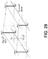
- h 0 is a bilinear interpolation of the expected signal values from the four nodes of the cell containing the robot (see Figure 29 ) as expressed in Eq. 49.
- Figure 29 illustrates bilinear interpolation from cell nodes.
- a 1-dimensional vector field that is, signal field, is illustrated.
- the bilinear interpolation is analogous according to Eq. 49.
- the ESEIF-SLAM variant is particularly interesting.
- the method is constant time, and space grows linear in the size of the area explored. This allows it to run on a low-end ARM7 processor clocked at 44 MHz with only 64 KByte of RAM.
- Figure 30 shows a sample grid consisting of 8 cells that models a vector field over an environment. Information links exist between nodes as they appear in an ESEIF-SLAM implementation.
- one embodiment of the ESEIF-SLAM approach updates robot pose, sensor calibration and the four cell nodes by integrating motion and sensor information. This results in information links between all involved variables, i.e. entries in the information matrix that correspond to robot pose, calibration, the four cell nodes, and the cross information between all of them are, in general, non-zero. In other words, the information matrix of a vector field of a single cell is fully dense.
- the ESEIF approach When moving into a neighboring cell, the ESEIF approach performs a sparsification step [14]. First, the process marginalizes over robot pose and sensor calibration. This removes them from the state vector and leaves the information matrix with only the node's information and their cross entries. Next, the process relocates robot and sensor calibration using a sensor measurement in the new cell, for example, as shown in [13].
- each node shares information with at most eight neighboring ones as the links in Figure 30 indicate.
- the nodes can be classified by the number of other nodes they link to. Only inner ones (nodes 6, 7 and 10) have eight connections. Nodes at the border have either 7 (node 11), 5 (nodes 2, 3, 5, 8, 9 and 14) or only 3 links (nodes 1, 4, 12, 13 and 15).
- the average connectivity per node is about 6. Of course this depends on the layout of the environment, for example, in an open room, the factor is larger as there are relatively more inner nodes.
- the space requirements for N nodes with signal dimension M can now be estimated. In the following, the robot and calibration variables are ignored temporarily as they merely add a constant term.
- the ESEIF stores an information vector (size N M), an estimate of the mean (also size N M) and the sparse information matrix. The latter holds N information matrices of all nodes which, due to symmetry, each use a size of 1 2 M M + 1 .
- the cross information can be stored in 1 2 ⁇ 6 M 2 where the factor 1 2 accounts for the fact that each link is shared between two nodes.
- the space requirements for Vector Field SLAM using the ESEIF are Space ESEIF ⁇ N 3 1 2 M 2 + 2 1 2 M + const .
- ESEIF-SLAM is constant time, i.e. does not depend on N [13].
- the most expensive operation is the recovery of a part of the estimated mean.
- we update robot pose, sensor calibration and the four cell nodes. This involves solving a linear equation system in these variables with a symmetric and positive definite system matrix. Cholesky decomposition is used, which takes time cubic in the number of variables. If constant terms and factors are ignored, the time complexity therefore is as expressed in Eq. 55 Time ESEIF O M 3 .
- beacons most home environments have walls and rooms separating the space into areas where at most one beacon is visible. In case the areas of beacons overlap, in one embodiment, information from all but one beacon is ignored, e.g. using the beacon that provides the highest signal certainty. In an alternative embodiment, information less than all available beacons is used, such as, for example, the two beacons with the highest signal certainty.
- a logic for switching from one beacon to another is described as follows. For each beacon, the signal certainty is measured, e.g. the signal strength, that indicates how useful the beacon is for localization. Initially, the beacon showing the best such certainty is selected and used as the current beacon. From then on the certainties of all available beacons are compared and after a beacon different from the current one shows a larger value (for example, a signal strength that is twice as strong) the process can switch to that beacon and make it the current one.
- the signal certainty e.g. the signal strength
- a natural choice of representing the environment is by using multiple localization maps, one for each area around a beacon. Whenever the robot switches the current beacon using the logic described above, a new localization map is started, or, if the robot has already visited the area before, it re-localizes in the corresponding localization map.
- the individual maps are allowed to overlap due to the hysteresis when switching the active beacon to another one.
- An example atlas of maps is shown in Figure 31 .
- the maps 3102, 3104, 3106 are linked by uncertain rigid-body transformations, i.e., they can rotate and translate slightly with respect to each other [15]. As long as the uncertainties associated with these transformations are small, each map can be anchored at a fixed global pose and the induced error moved into the procedure when re-localizing the robot in a localization map.
- the relative pose uncertainty computed from odometry from when the robot left a map is maintained until the robot re-enters it.
- this uncertainty can be limited to a certain maximum value.
- the uncertainty is then added to the pose uncertainty of the robot in our relocation step of the ESEIF [13]. This, of course, can introduce larger changes in the robot pose and should work well as long as the error when closing loops stays relatively small.
- One advantage of processing in this manner is that the signal dimension M stays the same as for a single beacon. Only the number N of nodes is larger for storing the additional maps.
- One embodiment includes performing SLAM in a first area associated with a first map; performing SLAM in a second area associated with a second map; and performing position estimation in a third area outside of and between the first area and the second area, wherein in the third area, position estimation is performed with dead reckoning.
- Dead reckoning can be performed using odometry and a gyroscope.
- a timer can be reset upon entry of the robot into the third area, the time spent in the third area can be tracked with the timer, and the robot can be controlled to return to at least one of the first area or the second area after a predetermined elapsed time in the third area.
- a controller further resets a timer upon entry of the robot into the third area from the first area or the second area; remembers which one of the first area or the second area the robot was in prior to entry to the third area; tracks time spent in the third area with the timer; and returns to the one of the first area or the second area from which the robot was in prior to entry to the third area after elapsing of a predetermined time in the third area unless the robot enters an area in which SLAM can be performed at least with positioning information based on observations of a set of one or more continuous signals.
- the controller further estimates a position uncertainty of the robot while operating in the third area; and if the position uncertainty is larger than a predetermined threshold, returns the robot to at least one of the first area or the second area. In one embodiment, the controller further estimates a position uncertainty of the robot while operating in the third area; remembers which one of the first area or the second area the robot was in prior to entry to the third area; and if the position uncertainty is larger than a predetermined threshold, returns the robot to the one of the first area or the second area from which the robot was in prior to entry to the third area.
- the controller is performs SLAM at least with positioning information based on observations of a first set of one or more continuous signals, and when in the second area, the controller performs SLAM at least with positioning information based on observations of a second set of one or more continuous signals.
- the first set of one or more continuous signals and the second set of one or more continuous signals comprise reflections of spots of infrared light.
- the controller distinguishes among the different reflections of spots of infrared light based on frequency.
- One embodiment includes a robot and a controller of the robot.
- the controller associates observations of a first set of one or more continuous signals with a first map; associates observations of a second set of one or more continuous signals with a second map, wherein the second map is maintained independently the first map; and switches between performing simultaneous localization and mapping (SLAM) with the first map or performing SLAM with the second map based at least partly on an observed signal strength of the first set or the second set.
- SLAM simultaneous localization and mapping
- the controller observes a plurality of sets of one or more continuous signals including the first set and the second set, wherein each of the plurality of observed sets is associated with a separate map; determines that a largest observed signal strength of the plurality of observed sets is larger in magnitude than a signal strength of a set currently being used for performing SLAM; and switches to performing SLAM with the set with the largest observed signal strength.
- the controller observes a plurality of sets of one or more continuous signals including the first set and the second set, wherein each of the plurality of observed sets is associated with a separate map; determines that a largest observed signal strength of the plurality of observed sets is at least a predetermined factor larger in magnitude than a signal strength of a set currently being used for performing SLAM; and switches to performing SLAM with the set with the largest observed signal strength.
- the predetermined factor can be a factor of 2.
- the first set of one or more continuous signals and the second set of one or more continuous signals include reflections of spots of infrared light. The controller can distinguish among the different reflections of spots of infrared light based on frequency.
- Any navigation system improves when integrating accurate information about the relative motion of the robot.
- the absolute error in orientation can be kept low, on-line SLAM filters like EKF-SLAM and ESEIF-SLAM are less likely to become inconsistent [17].
- the inputs of motor commands, wheel encoders and gyro measurements are analyzed for detecting movement errors.
- Ideal velocity values of both wheels are computed by a linear combination using system matrices with parameters depending on the detected error.
- wheel velocities are not computed but rather, the change in distance and rotation of the robot pose is directly provided.
- One embodiment is also simpler in that there is no need to adjust system parameters for combining encoders and gyro data depending on the movement error.
- Figure 32 illustrates a flowchart for computing motion of a robot from data measured by odometry and a gyroscope (yaw).
- the robot pose x t is then computed from the motion model in Eq. 46. See Figure 32 for a flowchart of updating the robot pose from the motion input.
- a typical motion model is one in which the robot is traveling on a straight line of distance d in the forward direction followed by an in-place rotation about ⁇ as expressed in Eq. 57.
- Figures 35A, 35B and 36 show flowcharts of possible systems for such a re-localization of the robot.
- Figures 35A and 35B illustrate different views of the same process for robot re-localization in which only one pose hypothesis is allowed.
- Figure 36 illustrates a process for robot re-localization in which multiple pose hypotheses are allowed.
- the processes begin with a measurement zt 3502.
- the process attempts to find 3504 a pose hypothesis. Further details of process to find 3504 a pose hypothesis will be described later in connection with Figures 37 and 38 .
- the robot has been re-localized and, in principle, could continue with its navigation. It is, however, beneficial to verify the found pose before deciding that the robot is fully re-localized.
- the found pose candidate is tracked 3510 using further measurements and motion estimates. Such a tracking 3510 can be carried out, e.g. by using an extended Kalman filter (EKF). After the pose has been tracked over a sufficient long distance or for a sufficient long time, the robot is considered as being fully re-localized.
- EKF extended Kalman filter
- a different embodiment includes choosing one best pose 3602 among all found candidates as illustrated in Figure 36 .
- the map includes the signal values at pre-defined locations (nodes). The association of measurements to nodes is implicit by choosing a grid cell in which the observation could have been taken (recall that signals carry a unique ID for identifying to which signal source a measurement belongs to). Depending on the distribution of the signals over the environment there can be multiple locations and cells in which a measurement could have been received. Choosing a best candidate pose under these conditions is less obvious.
- the multiple hypotheses could be tracked individually using a multi-hypothesis tracking (MHT) system.
- MHT multi-hypothesis tracking
- An example of such an approach is the multi-hypothesis localization and tracking approach by Arras et al. [20]. Eventually the number of hypotheses decreases as individual tracks are either confirmed and kept, or rejected and removed.
- the tracking of a pose is started after exactly one pose candidate has been found. Otherwise, the method retries using the scheme described above and shown in Figures 35A and 35B .
- a measurement z t Before searching for pose candidates, a measurement z t has to pass a significance test that evaluates how well the measurement is suited for the re-localization task. Basically, the measurement should contain rich enough information for giving a hint about where it could have been taken. The particular criteria employed depends on the sensor. It can be, for example, a minimum signal strength received in all measured signals. A measurement that fails the test is discarded and the system waits for the next one.
- w j depends on the selected cell i and robot position (x, y ) T
- m i j are the signal values at the four cell nodes according to Figure 29 .
- position (x, y) T falls into cell i as expressed in Eq. 62.
- b i 0 x ⁇ x ⁇ b i 1 , x , b i 0 , y ⁇ y ⁇ b i 2 , y .
- h c ⁇ 1 corrects measurement z t using calibration c (see Section 5).
- the calibration c is assumed to be known. Since the robot is re-localizing in a vector field that was learned before, calibration c can be obtained from the last system state of Vector Field SLAM. It is also possible to use a nominal value ⁇ or to ignore calibration in case its effects are negligible.
- w j is defined as in Eq. 50 to Eq. 53.
- A ⁇ l m i 0 + l m i 1 + l m i 2 ⁇ l m i 3 b i 1 , x ⁇ b i 0 , x b i 2 , y ⁇ b i 0
- a position ( x i , y i ) T can be obtained by minimizing the Mahalanobis distance as expressed in Eq. 76.
- x i , y i arg min x , y ⁇ i x , y T LH c ⁇ 1 Q t ⁇ 1 H c ⁇ 1 , T L T ⁇ i x , y
- a position ( x i, y i ) T can be obtained without using measurement covariance Q t as expressed in Eq. 77.
- x i , y i arg min x , y ⁇ ⁇ i x , y ⁇ .
- Position ( x i , y i ) T can be found by non-linear optimization, e.g. using the Levenberg-Marquardt algorithm.
- the Levenberg-Marquardt algorithm e.g. using the Levenberg-Marquardt algorithm.
- the minimum of Eq. 76 and Eq. 77can then be found by setting ⁇ i x i , y i 0 .
- one embodiment might not find the global minimum defined in Eq. 61 and Eq. 63 since for example the best node found in Eq. 66 and Eq. 69 can be a local extremum. Furthermore, since in one embodiment, only the cells at the best node are evaluated, there is no guarantee that a found pose is unique and that there are no other pose candidates in the vector field matching to measurement z t . It is therefore preferable to confirm the found pose by tracking it for some time.
- x t x ⁇ t + ⁇ ⁇ ⁇ H ⁇ T ⁇ ⁇ ⁇ 1 z t ⁇ h y ⁇ t .
- Rejected measurements are outliers either caused by excessive measurement noise or because they do not fit to the vector field around robot pose x t .
- C outlier By counting the number of outliers C outlier it can be verified that the pose hypothesis is correct. If the count reaches a maximum number C max then the tracking filter failed and we restart re-ocalization using the next measurement according to Figure 35A or 35B .
- the tracking filter ignores to covariances associated with the nodes in the map. We try to compensate for this somewhat by always using the same constant pose covariance ⁇ ⁇ when integrating measurements. Although this approach is not mathematically accurate, it is only used over a short distance of robot travel and only to verify our pose hypothesis. Thus, the consistency of this filter is not a primary concern.
- a property of the filter is that we only need to maintain the robot pose x t . This can be advantageous if we were to track several different pose hypotheses.
- Figure 37 is a flowchart illustrating a process for finding a pose hypothesis.
- the process selects the cell in which the measurement z t fits the best. For example, the measurement z t can be compared to the mean of the four nodes of each of the cells.
- the process computes the position within the cell found in the state 3702 where the measurement z t fits best. For example, the quadratic formula of Eq. 78 can be used.
- Figure 38 is a flowchart illustrating an alternative process for finding a pose hypothesis.
- the process selects the node where the measurement z t fits best, via , for example, Eq. 66 and Eq. 69.
- the process successively selects one of the four cells connected to the node.
- the process computes the position inside the selected cell where the measurement fits best, for example, by using the quadratic formula of Eq. 78.
- the decision block 3810 checks if there are more cells to investigate.
- the process obtains the orientation for the found position.
- the following can be performed: (a) the best position is selected, (b) the measurement can be rejected, and (c) all the found pose hypotheses can be outputted.
- a beacon projects a pair of unique infrared patterns on the ceiling (see Figure 1 ).
- the beacon can be placed relatively freely in the room and adjusted such that it points towards the ceiling.
- the projected patterns carry a different frequency encoded in the signal to ease the data association on the robot.
- Different Northstar beacons also provide different frequencies.
- the covariance Q t can be derived from z t along with two additional sensor outputs measuring the signal strength.
- the signal strengths are also used in the significance test in the re-localization procedure. In order to pass the test, the process requires that both spots are measured with a large enough intensity.
- the reported spot coordinates change linearly with the robot position.
- infrared light reaches the sensor not only by direct line-of-sight but also through multiple paths by reflecting off walls and other objects, so the spot coordinates change in a non-linear way as the robot approaches an obstructed area.
- the sensor plane may not be perfectly horizontal.
- the result of such small angular errors is well-approximated by a coordinate offset for both spots.
- this offset becomes apparent as rotational variability.
- h c ⁇ 1 for correcting measurements with respect to calibration is as expressed in Eq. 85.
- h c ⁇ 1 z t c z x 1 z y 1 z x 2 z y 2 ⁇ c x c y c x c y
- Function l 1 computes the distance to both spots, which does not depend on sensor orientation.
- the intuition behind l 2 is that the angle, between the measured spots does not depend on sensor orientation. The center between the spots rotated by - ⁇ , is then independent of sensor orientation.
- Such a robot can be, for example, an automatic floor cleaner or other floor treatment device, or a robotic toy.
- a user may pick up an autonomous floor cleaner to resupply the cleaner with cleaning fluid, to change a cloth or wiper, to empty out a receptable, etc. It would be desirable to have the autonomous floor cleaner restart where it had left off (resume) rather than start all over again.
- Some existing pickup detecting systems use for example switch sensors located at the wheels. As long as the robot is on the ground, the switch sensors at each wheel are closed due to the weight of the robot. When the robot is lifted, the switches trigger and detect that the robot is in mid air.
- One embodiment instead does not use a specific sensor but reuses other sensors on the robot and a logic that detects the pickup situation.
- One embodiment evaluates the signals of cliff sensors and a gyroscope for detecting a pickup.
- Cliff sensors are installed in most robotic products in order to detect the edges of areas where the robot could fall down. For example when moving closer and partly over the edge of a staircase leading downwards, these sensors trigger and provide the robot control software an input for changing the direction of travel in order not to drive or fall down the stairs.
- a gyroscope can be used for measuring the angular velocity in a robotic system. By integrating the data provided by the gyroscope over time, the orientation (yaw) of the robot can be determined. The accuracy of this estimate is often much better than those provided by other means, e.g. angular velocity determined by wheel odometers. It is therefore preferable to use a gyroscope as part of the localization system of the robot.
- one example of logic for detecting a pickup situation works as follows. As long as any of the cliff sensors do not trigger, the robot is assumed to be on the surface or ground, that is, not picked-up. This logic uses the fact that in general it is not possible to pick up the robot without triggering all cliff sensors. In the event where all cliff sensors trigger, further evaluation of sensor data is necessary. The robot either moved partly over the edge of a cliff or it might have been picked up. In order to detect in which of the two situations the robot is in, a specific pickup-detection procedure in the robot software is executed.
- the pickup-detection procedure first stops the robot and then evaluates the angular velocity measurements of the gyroscope. If these measurements indicate that the robot has a rotational velocity close to zero then no pickup is detected.
- the rationale behind this logic is that when picking up the robot, a user usually causes rotations and other disturbances that result in rotational velocities either far from zero or where the variance of the measured rotational velocity is large.
- Each visited cell is classified into one of the following categories:
- Table 1 shows the statistics of the environments with respect to occupancy and visibility to beacons. On average about 21 % of an environment is occupied by obstacles, floor changes or hazards. From roughly 56 % of visited places at least one beacon was visible (2 brightest levels of blue). The cleaning program continued to navigate in areas not covered by Northstar in about 23 % of the total environment explored.
- Table 2 shows our findings for the 25 runs. On average we obtain about 4 % of wrongly placed walls. In some cases there were none, while in others there can be as much as 10% of additional obstacles.
- the robot was paused and resumed during some runs as well, because either the user wanted to change the cleaning cloth or the robot got stuck (in some cases as many as 7 times. In either case, the robot was not necessarily started near the location where it was paused.
- the angular error is, on average, about 9.5° with outliers going as large as 23°. While this seems significant, it does not always lead to a catastrophic failure.
- the map of the environment is bent along its main direction. The robot is still able to successfully navigate from one side of the environment to the other one by changing its orientation along the path according to the learned localization map. Only when trying to close a loop over a longer trajectory with a larger error in rotation, the method is likely to fail.
- Figure 40A illustrates experimental results for position error in meters.
- Fig. 40A shows the mean position error of the localization approach on the three different map sizes and the two different functions l 1 and l 2 for mapping signal values to the orientation-invariant space, while also varying the tracking distance used for a successful localization.
- the zero tracking distance has a special meaning where as soon as a measurement generated a unique pose estimate no further verification via the EKF was performed.
- a minimum number of measurements is not enforced since in the experiment, the data contains a continuous stream of about 6 to 7 readings per second and the robot was traveling at an average speed of about 0.25 meter per second. Thus, a required minimum tracking distance also enforces an adequate minimum number of readings.
- FIG. 40B illustrates experimental results for position errors in percentages of errors above 1 meter. Similar to the position errors, the percentages drop quickly when tracking the robot pose over a short distance. Independent of which mapping function is used, the rates converge to similar values after tracking over a longer distance. For the l 2 function the rate is between 1 and 4 %.
- Pose is a position and orientation in space.
- pose can refer to a position ( x , y , z ) and an orientation ( ⁇ , ⁇ , ⁇ ) with respect to the axes of the three-dimensional space.
- pose can refer to a position (x, y ) in a plane and an orientation ⁇ relative to the normal to the plane.
- An optical sensor is a sensor that uses light to detect a condition and describe the condition quantitatively.
- an optical sensor refers to a sensor that can measure one or more physical characteristics of a light source. Such physical characteristics can include the number of photons, the position of the light on the sensor, the color of the light, and the like.
- Position-sensitive detector also known as a position sensing detector or a PSD, is an optical sensor that can measure the centroid of an incident light source, typically in one or two dimensions.
- a PSD can convert an incident light spot into relatively continuous position data.
- An imager refers to an optical sensor that can measure light on an active area of the sensor and can measure optical signals along at least one axis or dimension.
- a photo array can be defined as a one-dimensional imager
- a duo-lateral PSD can be defined as a two-dimensional imager.
- a camera typically refers to a device including one or more imagers, one or more lenses, and associated support circuitry.
- a camera can also include one or more optical filters and a housing or casing.
- PSD camera A PSD camera is a camera that uses a PSD.
- a projector refers to an apparatus that projects light.
- a projector includes an emitter, a power source, and associated support circuitry.
- a projector can project one or more light spots on a surface.
- a spot refers to a projection of light on a surface.
- a spot can correspond to an entire projection, or can correspond to only part of an entire projection.
- An optical position sensor is a device that includes one or more cameras, a signal processing unit, a power supply, and support circuitry and can estimate its position, distance, angle, or pose relative to one or more spots.
- Embodiments advantageously use active optical beacons in position estimation.
- disclosed techniques minimize or reduce the line-of-sight limitation of conventional active optical beacon-based localization by projecting the light sources onto a surface that is observable from a relatively large portion of the environment.
- the light sources can include sources of light that are not visible to the naked eye, such as, for example, infrared (IR) sources.
- IR infrared
- an autonomous mobile robot such as a robotic vacuum cleaner.
- a common approach to self-docking and self-charging is to place active infrared (IR) beacons on the charging station, which the robot can sense with photo detectors, and use the associated sensory information to find the docking station.
- IR infrared
- This approach suffers from line-of-sight limitations. If the robot and the docking station do not have line-of-sight separation, the robot cannot find its position relative to the docking station.
- the IR emitter can advantageously be placed in such a way that it projects onto the ceiling above the docking station, and a robot can have a photo detector that generally faces the ceiling or is capable of observing the ceiling.
- the robot can advantageously observe the IR projection on the ceiling even in the absence of line-of-sight separation between the robot and the docking station. In relatively many situations, the robot has a line-of-sight view of the ceiling, which enables the robot to detect the IR projection and move to the docking station for self-charging.
- Embodiments of the method and apparatus include systems for estimation of the distance of an object relative to another object, estimation of the bearing of an object relative to another object, estimation of the (x, y) position of an object in a two-dimensional plane, estimation of the (x, y, z) position of an object in three-dimensional space, estimation of the position and orientation of an object in two dimensions or in three dimensions, estimation of the linear or angular velocity of an object, and estimation of the linear or angular acceleration of an object.
- Embodiments of the method and apparatus are related to estimation of the position and orientation of a device, such as a mobile robot, relative to a global or a local coordinate system.
- the apparatus includes one or more optical sensors, one or more optical emitters, and signal processing circuitry.
- the initial position and orientations of the sensors can be unknown, and the apparatus and methods can be used to measure or estimate the position and orientation of one or more of the sensors and the position of the emitter projections on a surface.
- an optical sensor measures the optical signals generated by the optical emitters that are within the sensor's field of view by measuring the light that is projected onto a surface.
- optical devices for distance or position measurement disadvantageously require line-of-sight between the emitter and the sensor.
- embodiments described herein can detect optical signals projected onto a surface, such as a ceiling of an indoor environment.
- the optical emitters can be configured to project one or more spots of light onto a surface that is observable by a sensor from a relatively large portion of the environment. The sensor detects the spot and estimates the sensor's position relative to the spot.
- the sensor can measure quantities such as the position of the spot in the sensor's reference frame and the intensity of the signal generated by the spot, and can associate a unique identifier with each spot.
- Each such measurement or set of measurements defines a relationship between the position of the sensor and the position of the spot.
- signal processing circuitry can estimate the pose of at least one of the sensors, and, optionally, the position of one or more spots.
- Embodiments of the method and apparatus described herein can vary in the number and type of optical sensors used, can vary in the number and type of optical emitters used, can vary in the projection of the light onto the sensor via, optionally, one or more spots, and can vary in the methods used for estimation of the distance, heading, position, orientation, velocity, angular velocity, acceleration, and angular acceleration of the sensor or sensors.
- a light spot can be generated by an IR sensor that emits IR light onto a surface, and a photo detector can be used to detect the light reflected from the surface.
- the distance and relative heading to the projected light can be measured.
- the position of the sensor in a plane and the rotation of the sensor around an axis normal to that plane can be measured.
- Embodiments of the method and apparatus described herein can use a wide variety of optical sensors. Some embodiments use digital or analog imaging or video cameras, such as CMOS imagers, CCD imagers, and the like. Other embodiments use PSDs, such as one-dimensional PSDs, angular one-dimensional PSDs, two-dimensional PSDs, quad PSDs, duo-lateral PSDs, tetra-lateral PSDs, and the like. Other embodiments use photo detectors.
- the optical sensor is combined with a lens and one or more optical filters to form a camera.
- a PSD sensor can be enclosed in a casing with an open side that fits the lens and optical filters to filter incoming light and reduce effects of ambient light.
- Embodiments of the method and apparatus described herein can also use a wide variety of optical emitters, including visible light devices, invisible light devices, laser light devices, infrared light devices, polarized light devices, light-emitting diodes (LEDs), laser diodes, light bulbs, halogen lights, projectors, and the like.
- optical emitters including visible light devices, invisible light devices, laser light devices, infrared light devices, polarized light devices, light-emitting diodes (LEDs), laser diodes, light bulbs, halogen lights, projectors, and the like.
- One embodiment of the method and apparatus described herein uses one two-dimensional PSD camera and a plurality of infrared (IR) emitters.
- Each IR emitter projects a spot onto the ceiling in a room.
- Each emitter is modulated with a unique pattern or frequency.
- the PSD camera is mounted, on a robot, for example, and faces the ceiling in such a way that its field of view intersects at least a portion of the plane that defines the ceiling onto which the spots are projected.
- the PSD camera provides an indication of the projected position of each observable spot in the camera sensor coordinates. In the illustrated embodiment, the position of each observed spot is defined as its centroid.
- a camera position of each observed spot can correspond to the projection of a spot's position onto the image plane of the camera as defined by a corresponding perspective transformation.
- the PSD camera can measure the camera position of each spot. Using the measured camera positions of the spot and information related to the distance between the spots, the position (x, y) of the PSD camera in one plane and the rotation ( ⁇ ) of the PSD camera around an axis normal to that plane can be determined.
- the position and orientation of the camera defined by (x, y, ⁇ ) is known as the pose of the camera.
- the PSD camera can be coupled to a mobile device such as a robot, and the device's pose can advantageously be relatively accurately determined within a room with two or more spots.
- Pose estimation also known as localization, is an important component in many applications, including automated vacuuming, automated floor cleaning, telepresence, security, and entertainment. Without accurate position estimates, it is relatively difficult or impossible for a conventional robot to execute a path or trajectory because the conventional robot's internal position estimate tends to drift, and the conventional robot is generally unable to measure or account for the drift.
- a conventional robot without the ability to localize generally cannot maintain knowledge of the areas it has cleaned and the areas it has not cleaned, and the robot is therefore relatively likely to clean the same areas repeatedly and inefficiently and is relatively unlikely to clean other areas with sufficient frequency. Accordingly, many conventional robotic vacuum cleaners execute a random trajectory.
- a robotic vacuum cleaner according to an embodiment with the ability to localize in a relatively accurate manner can follow a relatively efficient planned path.
- a robotic vacuum cleaner according to an embodiment can clean a room in a relatively efficient manner because it can track its path and can execute a planned, traversable path.
- a mobile robot with the ability to localize can navigate to a desirable location and maintain a history of paths that it has taken.
- Another embodiment of the method and apparatus described herein uses one two-dimensional PSD camera and one IR emitter.
- the IR emitter projects a spot on the ceiling, and the PSD camera faces the ceiling such that its field of view intersects at least a portion of the plane that defines the ceiling onto which the spot is projected.
- the PSD camera can provide indications for a measurement of the distance from the camera to the spot and the heading from the camera to the spot relative to the tangent of the circle with radius defined by the distance measurement.
- the distance measurement defines a circle centered at the spot projected onto the plane of the camera.
- the illustrated embodiment can be used for an application in which it is desired to position a device relative to the spot.
- the camera position is at the center of the PSD camera.
- a mobile device can approach the charging station and recharge autonomously.
- a robotic vacuum cleaner can move along concentric circles or move along a spiral to implement a floor coverage strategy that is relatively efficient, compared to a random coverage strategy.
- Figure 41 illustrates a block diagram of components of one embodiment of an apparatus.
- the apparatus includes a projector 4111 and an optical position sensor 4112.
- the projector 4111 emits a light pattern 4113 onto a surface 4116, which creates a projected light pattern 4119.
- the light pattern 4113 is modulated.
- the reflection 4114 of the projected light pattern 4119 is projected onto the optical position sensor 4112.
- the projector 4111 includes a light source 4102.
- the light source 4102 can correspond to a device, such as a laser device, an infrared device, and the like, that can be modulated by a modulator 4101.
- the light from the light source 4102 can pass through one or more lenses 4103 to project the light onto the surface 4116.
- the optical position sensor 4112 includes a camera 4117 and a processing unit 4118.
- the camera 4117 can detect and measure the intensity and position of the light 4114 reflected from the surface 4116 and can generate corresponding signals that are processed by the signal processing unit 4118 to estimate the position of the optical position sensor 4112 relative to the projected light pattern 4119. It will be understood that the optical position sensor 4112 can include multiple cameras 4117 and/or multiple processing units 4118.
- the camera 4117 includes an imager 4104.
- the imager 4104 can, for example, correspond to a CMOS imager, a CCD imager, an infrared imager, and the like.
- the camera can optionally include an optical filter 4105 and can optionally include a lens 4106.
- the lens 4106 can correspond to a normal lens or can correspond to a special lens, such as a wide-angle lens, a fish-eye lens, an omni-directional lens, and the like. Further, the lens 4106 can include reflective surfaces, such as planar, parabolic, or conical mirrors, which can be used to provide a relatively large field of view or multiple viewpoints.
- the lens 4106 collects the reflected light 4114 and projects it onto the imager 4104.
- the optical filter 4105 can constrain the wavelengths of light that pass from the lens 4106 to the imager 4104, which can advantageously be used to reduce the effect of ambient light, to narrow the range of light to match the wavelength of the light coming from the projector 4111, and/or to limit the amount of light projected onto the imager 4104, which can limit the effects of over-exposure or saturation.
- the filter 4105 can be placed in front of the lens 4106 or behind the lens 4106. It will be understood that the camera 4117 can include multiple imagers 4104, multiple optical filters 4105, and/or multiple lenses 4106.
- the signal processing unit 4118 can include analog components and can include digital components for processing the signals generated by the camera 4117.
- the major components of the signal processing unit 4118 preferably include an amplifier 4107, a filter 4108, an analog-to-digital converter 4109, and a microprocessor 4110, such as a peripheral interface controller, also known as a PIC. It will be understood that the signal processing unit 4118 can include multiple filters 4108 and/or multiple microprocessors 4110.
- Embodiments of the apparatus are not constrained to the specific implementations of the projector 4111 or the optical position sensor 4112 described herein. Other implementations, embodiments, and modifications of the apparatus that do not depart from the true spirit and scope of the apparatus will be readily apparent to one of ordinary skill in the art.
- FIG 42 illustrates an example of a use for the position estimation techniques.
- An environment includes a ceiling 4206, a floor 4207, and one or more walls 4208.
- a projector 4203 is attached to a wall 4208. It will be understood that the projector 4203 can have an internal power source, can plug into a wall outlet or both.
- the projector 4203 projects a first spot 4204 and a second spot 4205 onto the ceiling 4206.
- An optical position sensor 4202 is attached to a robot 4201.
- the optical position sensor 202 can detect the spots 4204, 4205 on the ceiling 4206 and measure the position (x, y ) of the robot 4201 on the floor plane and the orientation ⁇ of the robot 4201 with respect to the normal to the floor plane.
- the pose of the robot 4201 is measured relative to a global coordinate system.
- Figure 43 describes a geometrical model associated with one embodiment of the method and apparatus described earlier in connection with Figure 42 .
- the ceiling 4206 lies at a height h above the floor 4207.
- a point w 1 4301 lies at the centroid of the first spot 4204, and a point w 2 4302 lies at the centroid of the second spot 4205.
- a global coordinate system with an X axis, a Y axis, and a Z axis is defined and is also referred to as the global reference frame.
- the Y axis such that the Y axis is parallel to the vector originating at the point w 1 4301 and passing through the point w 2 4302.
- the X axis such that the X axis is perpendicular to the Y axis and lies in the plane defined by the floor.
- the Z axis is normal to the floor plane and is directed from the floor to the ceiling.
- an origin O is defined as the point having coordinates (0, 0, 0).
- the point w 1 4301 is defined as having coordinates (x 1 , y 1 , h ), and the point w 2 4302 is defined as having coordinates (x 2 , y 2 , h).
- the point w 1 4301 has the coordinates (0, 0, h )
- the point w 2 4302 has the coordinates (0, y 2 . h). It will be understood that the aforementioned definitions can be made with no loss of generality.
- a coordinate system relative to an imager is defined with a u axis, a v axis, and a z axis and can be referred to as the camera coordinate system or the camera reference frame.
- the imager corresponds to a two-dimensional PSD sensor.
- the height of the PSD sensor off the floor plane is relatively small compared to the ceiling height h, so the PSD sensor and the origin of the camera coordinate system use the coordinates ( x , y , 0) and the orientation ⁇ in the global coordinate system.
- the point c 1 4311 represents the projection of the point w 1 4301 onto the imager
- the point c 2 4312 represents the projection of the point w 2 4302 onto the imager.
- the point c 1 4311 has the coordinates ( u 1 , v 1 , 0) in the camera reference frame
- the point c 2 4312 has the coordinates ( u 2 , v 2 , 0) in the camera reference frame. It will be understood that the aforementioned definitions can be made with no loss of generality.
- the spots 4204, 4205 can be identified using unique signals or unique signatures.
- the emitters that produce the spots 4204, 4205 can be on-off modulated with different frequencies.
- the emitter that produces the first spot 4204 can be modulated with a first frequency f 1
- the emitter that produces the second spot 4205 can be modulated with a second frequency f 2 , wherein the first frequency and the second frequency are different; that is f 1 ⁇ f 2 .
- the ceiling height h and the separation y 2 between the point w 1 4301 and the point w 2 4302 can be determined in a variety of ways. For example, if the mobile robot 4201 using the optical position sensor is capable of producing wheel odometry estimates, then the robot 4201 can estimate h and y 2 using measurements or observations of the points w 1 4301 and w 2 4302 from multiple positions. Other appropriate techniques will be readily determined by one of ordinary skill in the art.
- the PSD camera can measure c 1 and c 2 , which correspond to the projections of w 1 and w 2 onto the PSD sensor.
- a goal of the method is to determine S, the position of the PSD camera in the global reference frame.
- the PSD measures the coordinates of the centroid of the light projected onto the PSD by generating electrical current proportional to the position and intensity of the light centroid.
- the associated processing can be accomplished in a wide variety of ways, including analog circuitry, digital circuits, hardware, software, firmware, and combinations thereof.
- a microcontroller, a microprocessor, a CPU, a general-purpose digital signal processor, dedicated hardware, and the like can be used.
- the sensor preferably does not become saturated with light, ambient or otherwise. In one embodiment, this is accomplished by using optical filters to reduce or minimize unwanted light sources that project onto the active area of the PSD sensor and by biasing the PSD to increase the light level at which it becomes saturated.
- One approach is to isolate one light source is to modulate the light source with a unique pattern such that it is distinguished from other light sources.
- the PSD sensor can extract the signal generated by filtering a signal using a band-pass filter with lower and upper frequencies of f i - w and f i + w , respectively, where 2w corresponds to the width of the corresponding band-pass filter.
- the signal processing unit of the PSD can use the filter to suppress signals with frequencies outside the frequency range defined by the band-pass filter.
- the filtering of the PSD signal can occur either before or after the PSD currents are converted into associated centroid positions.
- the signal processing unit filters the signal specified by f 1 to measure c 1 , the centroid of the first spot, and filters the signal specified by f 2 to measure c 2 , the centroid of the second spot.
- the apparatus includes N emitters, which project N light spots, and M cameras.
- the position of the j-th light spot is denoted herein by w j
- the position of the projection of the j-th spot onto the i-th camera is denoted herein by c i , j .
- P i represents the perspective transformation associated with the i-th camera.
- Eq. 90 defines three equations for six unknowns, in which the unknowns are x i , y i , z i , ⁇ i , ⁇ i , and ⁇ i .
- N ⁇ M such matrix equations can be formulated, but not all such equations are necessarily unique, independent, and non-degenerate.
- values for x , y , and ⁇ can be determined.
- the system includes two spots projected onto the ceiling and one optical position sensor with one PSD camera.
- S represents the position of the PSD camera in the global reference frame
- P represents the transformation from a point ( X , Y , Z ) in the global coordinate system to a point ( u , v , z ) in the PSD camera reference frame.
- the z axis of the camera coordinate system is aligned with the Z axis of the global coordinate system in the vertical direction. This implies that R ⁇ and R ⁇ correspond to identity matrices; accordingly, R ⁇ and R ⁇ have been omitted from Eq. 91.
- Eq. 93 P -1 represents the inverse perspective transformation
- R ⁇ -1 represents the inverse rotation transformation.
- Eq. 93 defines two non-degenerate equations in three unknowns x , y , and ⁇ for each measurement c j .
- the three variables,, x , y , and ⁇ together determine the pose of the PSD camera.
- Eq. 94 relates the spot w 1 with its associated PSD camera position c 1
- Eq. 95 relates the spot w 2 with its associated PSD camera position c 2 .
- Subtracting Eq. 94 from Eq. 95 generates the following matrix equation expressed in Eq. 96.
- w 2 ⁇ w 1 R ⁇ ⁇ 1 P ⁇ 1 c 2 ⁇ c 1
- Eq. 97 The matrix equation given in Eq. 97 expresses two non-degenerate linear equations.
- ⁇ u u 2 - u 1
- 0 P ⁇ 1 ⁇ u cos ⁇ ⁇ ⁇ sin ⁇
- the pose ( x , y , ⁇ ) of the PSD camera as a function of the measurements c 1 and c 2 can be determined using Eq. 98 and Eq. 99.
- Eq. 102 specifies two non-degenerate linear equations.
- P -1 corresponds to a scalar or to a scalar multiple of an identity matrix
- squaring and summing the two non-degenerate linear equations and simplifying the result yields the following.
- and the corresponding distance measurement
- can define a circle in an x-y plane centered at the origin (0, 0) with radius
- a tangent to the circle at the position of the sensor at the position of the sensor (that is, at S ), is orthogonal to the vector s (x y ) T , where the superscripted " T " denotes the vector or matrix transposition operation.
- the rotational orientation, ⁇ of the robot of the robot with respect to scan then be estimated using a measurement of c as given in the following relationship.
- ⁇ tan ⁇ 1 u / ⁇
- the spot is projected onto the ceiling directly above a docking station, and the optical position sensor with one PSD camera is attached to a robot.
- the robot can guide itself to turn toward the spot and approach the spot. In this manner, the robot can approach the docking station and recharge itself.
- the projector can correspond to a handheld projector and can be used to point above a user-selected object or location of interest to guide to the robot to the object or location. This alternative example provides a powerful interface for robot interaction.
- One embodiment of the method and apparatus includes a camera, such as a CCD camera, a CMOS camera, and the like, and a projector that generates a pattern on a projection surface, such as a ceiling.
- a camera such as a CCD camera, a CMOS camera, and the like
- a projector that generates a pattern on a projection surface, such as a ceiling.
- the projector can correspond to a slide projector, and the pattern can be encoded in a slide.
- at least one pattern has the shape of a circle, and in another embodiment, at least one pattern has the shape of a square.
- Each camera generates grayscale or color images.
- a signal processing unit processes the camera images, extracts the unique patterns, and estimates a position of the pattern in camera sensor coordinates. The position of the pattern can be defined as the centroid of the pattern.
- the position of the j-th pattern in the global reference frame can be denoted herein by w j
- the position of the j-th pattern in the reference frame of the i-th camera can be denoted herein by c i , j
- the relationship between the j-th pattern and its projection onto the i-th camera is defined by Eq. 90.
- the signal processing unit captures the camera images and processes the images using one or more image analysis techniques to detect and extract the position of known patterns.
- the image analysis techniques can include, by way of example, line and corner detection (to detect a square pattern, for example), Hough transform (to detect a circle, for example), and the like.
- the signal processing unit can estimate the positions of the cameras with respect to the global reference frame using the methods described previously.
- one or more of the projectors can modulate on-off to reduce the effects of ambient light.
- the modulation frequencies can advantageously be used to associate a unique identifier with each pattern.
- the identifier of a pattern is advantageously encoded within the pattern itself.
- the shape of the pattern can define a unique identifier, if distinct shapes are used for each pattern. For example, the system can distinguish between a square pattern and a circular pattern and associate different identifiers with each pattern.
- the modulation frequency of the projector can encode information, such as bit patterns to transmit a message that can be detected and extracted by the camera and the signal processing unit.
- the bit patterns can be modulated in the signal using any of a variety of common modulation techniques, such as pulse width modulation, space width modulation, and phase modulation.
- the bit patterns are modulated on top of the original "carrier" frequency of the spot.
- the projectors and optical position sensors can advantageously be used for optical wireless communication.
- the projector projects the light pattern on a reflecting surface, and the optical sensor detects the signal by viewing the reflecting surface, which eliminates the need for line-of-sight between the emitter and the sensor.
- the signal modulated in the projected light can carry commands, such as commands for a robot, similar to the way in which light modulated by a remote control unit can carry commands to an appliance.
- the projection of the spot on the ceiling directly above a docking station enables the robot to find the docking station and perform self-charging.
- an interface with the docking station such as a button on the docking station, can generate a command to the robot to return to the charging station.
- Yet another embodiment of the method and apparatus includes a projector for one or more distinct regions of an environment, such as a projector for each distinct region.
- this embodiment expands the coverage of localization throughout relatively large areas or throughout multiple relatively confined areas, such as multiple rooms.
- the covered area associated with one projector can be constrained by the field of view of the camera, the distance from the projector to the reflection surface, and the presence of objects and walls that obstruct the camera's view of the spot. Increasing the number of light patterns can increase the coverage area.
- one or more projectors are provided for each room in which coverage is desired, so that, for example, each room can have a dedicated projector.
- each projector can project one or more spots that have an identifier that is unique within the room.
- the identifier associated with a spot can be based on the spot's modulation frequency, the spot's shape, the spot's color, or another appropriate characteristic that can be detected by the camera sensor.
- the combination of the individual spot identifiers with a room can define a unique identifier for the room.
- a first room can have two spots having associated unique identifiers "A" and "B”
- a second room can have two spots having associated unique identifiers "A” and "C.”
- the unique identifiers for each room can advantageously be used by a system, such as by a robot, to build a topological map of the rooms and the connectivity of the rooms. Without a unique identifier for each room or region, the system can disadvantageously generate ambiguous position information.
- the position associated with an (x, y ) coordinate of a first room can generally not be distinguished from the position associated with the (x, y ) coordinate of a second room.
Landscapes
- Engineering & Computer Science (AREA)
- Physics & Mathematics (AREA)
- Radar, Positioning & Navigation (AREA)
- Remote Sensing (AREA)
- General Physics & Mathematics (AREA)
- Automation & Control Theory (AREA)
- Aviation & Aerospace Engineering (AREA)
- Electromagnetism (AREA)
- Computer Networks & Wireless Communication (AREA)
- Control Of Position, Course, Altitude, Or Attitude Of Moving Bodies (AREA)
Claims (15)
- Appareil, comprenant :un robot (100) ; etun contrôleur du robot configuré pour :réaliser une localisation et une cartographie simultanées pour l'apprentissage de la répartition spatiale d'un ou de plusieurs signaux continus dans un environnement dans lequel le robot (100) est en train de naviguer, calculer une pose du robot au moyen de la localisation et de la cartographie simultanées à mesure que le robot se déplace le long d'une surface pour générer une ou plusieurs cartes,la pose comprenant une position et une orientation du robot (100),chacune des une ou plusieurs cartes comportant un champ vectoriel défini par des vecteurs signal sur l'espace de valeurs de mesure des un ou plusieurs signaux continus attendues pour diverses positions le long de la surface (150) ;naviguer le robot de telle sorte que le robot traite la surface (150) d'une manière méthodique ;caractérisé en ce que le contrôleur du robot est configuré pour :
déterminer que le fonctionnement du robot a été momentanément interrompu et, suite à la reprise du fonctionnement du robot :relocaliser le robot (100) au sein d'une carte parmi les une ou plusieurs cartes sans effacer les une ou plusieurs cartes ; etreprendre le traitement de la surface de la manière méthodique,le robot étant configuré pour se repositionner dans une zone précédemment cartographiée lors de la reprise du fonctionnement en recherchant, dans le champ vectoriel, des positions qui fournissent un vecteur signal ajusté à des mesures de capteurs du robot,le contrôleur étant configuré en outre pour renvoyer le robot (100) à une pose précédente préalablement à la reprise du traitement, la pose précédente provenant d'un instant antérieur à l'événement d'interruption momentanée, la pose précédente comprenant une position antérieure et une orientation antérieure. - Appareil selon la revendication 1, dans lequel le contrôleur est configuré en outre pour reprendre le traitement de la surface (150) sensiblement sans retraiter des zones de la surface déjà traitées préalablement à l'événement d'interruption momentanée.
- Appareil selon la revendication 1, dans lequel, pour relocaliser le robot, le contrôleur est configuré en outre pour :obtenir un ensemble actuel de mesures de capteurs effectivement observées ;convertir l'ensemble actuel de mesures de capteurs effectivement observées en mesures de capteurs converties, les mesures de capteurs converties étant indépendantes de l'orientation du robot ;comparer les mesures de capteurs converties à une pluralité de mesures de capteurs des une ou plusieurs cartes correspondant à des positions différentes au sein des une ou plusieurs cartes ; etidentifier une pose parmi la pluralité de positions des une ou plusieurs cartes, la pose comprenant une position et une orientation du robot.
- Appareil selon la revendication 3, dans lequel, pour comparer, le contrôleur est configuré en outre pour :calculer une proximité entre les mesures de capteurs converties et la pluralité de mesures de capteurs pour des nœuds de la carte ;sélectionner une cellule sur la base de la proximité calculée pour ses nœuds ;interpoler au sein de la cellule dans le but de générer la position de la pose ; etanalyser l'ensemble actuel de mesures de capteurs effectivement observées dans le but de générer une orientation de la pose.
- Appareil selon la revendication 4, dans lequel, pour comparer, le contrôleur est configuré en outre pour :calculer une proximité entre les mesures de capteurs converties et la pluralité de mesures de capteurs pour des nœuds de la carte ;sélectionner un nœud sur la base de la proximité ;pour une cellule adjacente au nœud sélectionné, interpoler dans la cellule dans le but de générer la position de la pose ; etanalyser l'ensemble actuel de mesures de capteurs effectivement observées dans le but de générer une orientation de la pose.
- Appareil selon l'une des revendications précédentes, dans lequel le robot (100) est adapté à s'interrompre momentanément en réponse à un événement à l'initiative d'un utilisateur.
- Procédé d'estimation d'une pose d'un robot (100), le procédé comprenant :la réalisation d'une localisation et d'une cartographie simultanées pour l'apprentissage de la répartition spatiale d'un ou de plusieurs signaux continus dans un environnement dans lequel le robot est en train de naviguer ;le calcul de la pose du robot au moyen de la localisation et de la cartographie simultanées à mesure que le robot se déplace le long d'une surface (150) pour générer une ou plusieurs cartes, la pose comprenant une position et une orientation du robot, chacune des une ou plusieurs cartes comportant un champ vectoriel défini par des vecteurs signal sur l'espace de valeurs de mesure des un ou plusieurs signaux continus attendues pour diverses positions le long de la surface ;la navigation du robot de telle sorte que le robot (100) traite la surface d'une manière méthodique ;la détermination que le fonctionnement du robot a été momentanément interrompu et, suite à la reprise du fonctionnement du robot :la relocalisation du robot au sein d'une carte parmi les une ou plusieurs cartes sans effacement des une ou plusieurs cartes ;le renvoi du robot à un pose précédente préalablement à la reprise du traitement,la pose précédente provenant d'un instant antérieur à l'événement d'interruption momentanée, la pose précédente comprenant une position antérieure et une orientation antérieure ; etla reprise du traitement de la surface (150) de la manière méthodique,le robot étant configuré pour se repositionner dans une zone précédemment cartographiée lors de la reprise du fonctionnement en recherchant, dans le champ vectoriel, des positions qui fournissent un vecteur signal ajusté avec des mesures de capteurs du robot.
- Procédé selon la revendication 7, comprenant en outre la reprise du traitement de la surface sensiblement sans retraitement de zones de la surface (150) déjà traitées préalablement à l'événement d'interruption momentanée.
- Procédé selon la revendication 7, dans lequel la relocalisation comprend en outre :l'obtention d'un ensemble actuel de mesures de capteurs de lumière effectivement observées ;la comparaison des mesures de capteurs de lumière effectivement observées à une pluralité de mesures de capteurs de lumière des une ou plusieurs cartes correspondant à des positions différentes au sein des une ou plusieurs cartes ; etl'identification d'une pose parmi la pluralité de positions des une ou plusieurs cartes, la pose comprenant une position et une orientation du robot.
- Procédé selon la revendication 9, dans lequel la relocalisation comprend en outre :l'obtention d'un ensemble actuel de mesures de capteurs de lumière effectivement observées ;la conversion de l'ensemble actuel de mesures de capteurs de lumière effectivement observées en mesures de capteurs de lumière converties, les mesures de capteurs de lumière converties étant indépendantes de l'orientation du robot ;la comparaison des mesures de capteurs de lumière converties à une pluralité de mesures de capteurs de lumière des une ou plusieurs cartes correspondant à des positions différentes au sein des une ou plusieurs cartes ; etl'identification d'une pose parmi la pluralité de positions des une ou plusieurs cartes, la pose comprenant une position et une orientation du robot.
- Procédé selon la revendication 10, dans lequel la comparaison comprend en outre :le calcul d'une proximité entre les mesures de capteurs de lumière converties et la pluralité de mesures de capteurs de lumière pour des nœuds de la carte ;la sélection d'une cellule sur la base de la proximité calculée pour ses nœuds ;l'interpolation au sein de la cellule dans le but de générer la position de la pose ; etl'analyse de l'ensemble actuel de mesures de capteurs de lumière effectivement observées dans le but de générer une orientation de la pose.
- Procédé selon la revendication 8, comprenant en outre la confirmation de la pose identifiée par suivi plus poussé de la pose du robot (100) et comparaison d'un compte de mesures aberrantes à une valeur dans le but de confirmer ou de rejeter la pose identifiée.
- Procédé selon la revendication 10, dans lequel la comparaison comprend en outre :le calcul d'une proximité entre les mesures de capteurs de lumière converties et la pluralité de mesures de capteurs de lumière pour des nœuds de la carte ;la sélection d'un nœud sur la base de la proximité ;pour une cellule adjacente au nœud sélectionné, l'interpolation dans la cellule dans le but de générer la position de la pose ; etl'analyse de l'ensemble actuel de mesures de capteurs de lumière effectivement observées dans le but de générer une orientation de la pose.
- Procédé selon la revendication 7, dans lequel la détermination que le fonctionnement du robot (100) a été momentanément interrompu comprend en outre la détermination que le robot (100) a été soulevé de la surface, la commande du robot pour assurer son immobilisation, et la détection d'un mouvement à l'aide d'un gyroscope.
- Procédé selon la revendication 7, dans lequel la détermination que le fonctionnement du robot (100) a été momentanément interrompu comprend en outre la détection d'une interaction d'un utilisateur avec une fonction d'interruption momentanée du robot.
Applications Claiming Priority (2)
| Application Number | Priority Date | Filing Date | Title |
|---|---|---|---|
| US201161558831P | 2011-11-11 | 2011-11-11 | |
| PCT/US2012/064553 WO2013071190A1 (fr) | 2011-11-11 | 2012-11-09 | Mise à l'échelle de slam de champ vectoriel à de grands environnements |
Publications (3)
| Publication Number | Publication Date |
|---|---|
| EP2776216A1 EP2776216A1 (fr) | 2014-09-17 |
| EP2776216A4 EP2776216A4 (fr) | 2015-12-30 |
| EP2776216B1 true EP2776216B1 (fr) | 2022-08-31 |
Family
ID=48290637
Family Applications (1)
| Application Number | Title | Priority Date | Filing Date |
|---|---|---|---|
| EP12848273.4A Active EP2776216B1 (fr) | 2011-11-11 | 2012-11-09 | Appareil robot et méthode de commande pour reprendre le fonctionnement après une pause. |
Country Status (3)
| Country | Link |
|---|---|
| US (3) | US20140031980A1 (fr) |
| EP (1) | EP2776216B1 (fr) |
| WO (1) | WO2013071190A1 (fr) |
Cited By (1)
| Publication number | Priority date | Publication date | Assignee | Title |
|---|---|---|---|---|
| US20240208058A1 (en) * | 2022-12-22 | 2024-06-27 | Boston Dynamics, Inc. | Methods and apparatus for automated ceiling detection |
Families Citing this family (257)
| Publication number | Priority date | Publication date | Assignee | Title |
|---|---|---|---|---|
| US10493629B2 (en) | 2016-05-27 | 2019-12-03 | Ge Global Sourcing Llc | Multisensory data fusion system and method for autonomous robotic operation |
| US10809071B2 (en) | 2017-10-17 | 2020-10-20 | AI Incorporated | Method for constructing a map while performing work |
| AU2011305154B2 (en) * | 2010-09-24 | 2015-02-05 | Irobot Corporation | Systems and methods for VSLAM optimization |
| KR20120044768A (ko) * | 2010-10-28 | 2012-05-08 | 엘지전자 주식회사 | 로봇 청소기 및 이의 제어 방법 |
| US8791901B2 (en) * | 2011-04-12 | 2014-07-29 | Sony Computer Entertainment, Inc. | Object tracking with projected reference patterns |
| WO2013071190A1 (fr) | 2011-11-11 | 2013-05-16 | Evolution Robotics, Inc. | Mise à l'échelle de slam de champ vectoriel à de grands environnements |
| US11093722B2 (en) | 2011-12-05 | 2021-08-17 | Adasa Inc. | Holonomic RFID reader |
| US10846497B2 (en) | 2011-12-05 | 2020-11-24 | Adasa Inc. | Holonomic RFID reader |
| KR101901483B1 (ko) * | 2012-01-17 | 2018-09-21 | 아셀산 엘렉트로닉 사나이 베 티카렛 아노님 시르케티 | 추적 시스템 정확성 측정을 위한 시스템 및 방법 |
| WO2013112842A1 (fr) * | 2012-01-25 | 2013-08-01 | Adept Technology, Inc. | Système d'évitement d'obstacles positifs et négatifs pour un robot mobile |
| US9138116B2 (en) * | 2012-05-07 | 2015-09-22 | Joseph Y. Ko | Movement operation system for autonomous moving cleaning apparatus |
| US8744662B2 (en) * | 2012-05-07 | 2014-06-03 | Joseph Y. Ko | Method for operating autonomous moving cleaning apparatus |
| US9144362B2 (en) * | 2012-05-07 | 2015-09-29 | Joseph Y. Ko | Movement operation system for autonomous moving cleaning apparatus |
| US8983662B2 (en) * | 2012-08-03 | 2015-03-17 | Toyota Motor Engineering & Manufacturing North America, Inc. | Robots comprising projectors for projecting images on identified projection surfaces |
| US9178370B2 (en) | 2012-12-28 | 2015-11-03 | Irobot Corporation | Coverage robot docking station |
| KR20140089241A (ko) * | 2013-01-04 | 2014-07-14 | 한국전자통신연구원 | 군집지능로봇에서의 확률기반 전파맵 생성 장치 및 방법 |
| KR101490170B1 (ko) * | 2013-03-05 | 2015-02-05 | 엘지전자 주식회사 | 로봇 청소기 |
| US9956494B2 (en) | 2013-03-15 | 2018-05-01 | Rnd By Us B.V. | Element comprising sensors for detecting grab motion or grab release motion for actuating inter-element holding or releasing |
| US10093488B2 (en) | 2013-03-15 | 2018-10-09 | Rnd By Us B.V. | Shape-shifting a configuration of reusable elements |
| NL2013466B1 (en) * | 2014-09-12 | 2016-09-28 | Rnd By Us B V | Shape-Shifting a Configuration of Reusable Elements. |
| US10165255B2 (en) | 2013-03-20 | 2018-12-25 | Trimble Inc. | Indoor navigation via multi-beam laser projection |
| US10643351B2 (en) * | 2013-03-20 | 2020-05-05 | Trimble Inc. | Indoor navigation via multi beam laser projection |
| US20140288824A1 (en) * | 2013-03-22 | 2014-09-25 | Qualcomm Incorporated | Method and/or system for selective application of direction of travel |
| KR102061511B1 (ko) * | 2013-04-26 | 2020-01-02 | 삼성전자주식회사 | 청소 로봇, 홈 모니터링 장치 및 그 제어 방법 |
| FR3006477B1 (fr) * | 2013-05-29 | 2016-09-30 | Blinksight | Dispositif et procede de detection de la manipulation d'au moins un objet |
| WO2015013418A2 (fr) * | 2013-07-23 | 2015-01-29 | The Regents Of The University Of California | Procédé de traitement de mesures d'éléments pendant une navigation inertielle assistée par la vision |
| US9400930B2 (en) | 2013-09-27 | 2016-07-26 | Qualcomm Incorporated | Hybrid photo navigation and mapping |
| US9552007B2 (en) | 2013-12-19 | 2017-01-24 | International Business Machines Corporation | Parallel technique for computing problem functions in solving optimal power flow |
| US10612939B2 (en) * | 2014-01-02 | 2020-04-07 | Microsoft Technology Licensing, Llc | Ground truth estimation for autonomous navigation |
| US10514837B1 (en) * | 2014-01-17 | 2019-12-24 | Knightscope, Inc. | Systems and methods for security data analysis and display |
| US10279488B2 (en) | 2014-01-17 | 2019-05-07 | Knightscope, Inc. | Autonomous data machines and systems |
| US9329597B2 (en) | 2014-01-17 | 2016-05-03 | Knightscope, Inc. | Autonomous data machines and systems |
| WO2015128143A1 (fr) * | 2014-02-26 | 2015-09-03 | Koninklijke Philips N.V. | Estimation de position de source de lumière d'un luminaire à partir d'une empreinte de lumière |
| TWI505801B (zh) * | 2014-05-09 | 2015-11-01 | Kinpo Elect Inc | 室內機器人與其定位方法 |
| KR102293615B1 (ko) * | 2014-07-02 | 2021-08-26 | 삼성전자주식회사 | 청소 로봇 및 그 제어 방법 |
| US9459104B2 (en) | 2014-07-28 | 2016-10-04 | Google Inc. | Systems and methods for performing a multi-step process for map generation or device localizing |
| US10209062B1 (en) | 2014-08-01 | 2019-02-19 | Google Llc | Use of offline algorithm to determine location from previous sensor data when location is requested |
| US10240995B2 (en) | 2014-08-01 | 2019-03-26 | Google Llc | Construction of a surface of best GPS visibility from passive traces using SLAM for horizontal localization and GPS readings and barometer readings for elevation estimation |
| US9838846B1 (en) | 2014-08-01 | 2017-12-05 | Google Llc | Extraction of walking direction from device orientation and reconstruction of device orientation during optimization of walking direction |
| US10989531B2 (en) * | 2014-08-15 | 2021-04-27 | Commonwealth Scientific And Industrial Research Organisation | Method of setting-up a range-based tracking system utilizing a tracking coordinate system |
| US9880257B2 (en) * | 2014-09-11 | 2018-01-30 | Google Llc | Gaussian process-based approach for identifying correlation between wireless signals |
| US9838847B2 (en) | 2014-09-11 | 2017-12-05 | Google LLP | Data driven evaluation and rejection of trained Gaussian process-based wireless mean and standard deviation models |
| US9810762B2 (en) | 2014-09-11 | 2017-11-07 | Google Inc. | Calculating mean wireless signal strengths using a gaussian process approach incorporating predictive standard deviations |
| US9804594B2 (en) * | 2014-11-07 | 2017-10-31 | Clearpath Robotics, Inc. | Self-calibrating sensors and actuators for unmanned vehicles |
| KR102339531B1 (ko) | 2014-12-16 | 2021-12-16 | 에이비 엘렉트로룩스 | 로봇 청소 장치를 위한 경험-기반의 로드맵 |
| JP6532530B2 (ja) * | 2014-12-16 | 2019-06-19 | アクチエボラゲット エレクトロルックス | ロボット掃除機の掃除方法 |
| US10488865B2 (en) * | 2014-12-16 | 2019-11-26 | Al Incorporated | Methods and systems for robotic surface coverage |
| US9701020B1 (en) * | 2014-12-16 | 2017-07-11 | Bobsweep Inc. | Method and system for robotic surface coverage |
| SE538373C2 (en) | 2014-12-23 | 2016-05-31 | Husqvarna Ab | Improved navigation for a robotic lawnmower |
| SE540131C2 (en) * | 2014-12-24 | 2018-04-10 | Husqvarna Ab | Robotic work tool with trajectory correction |
| US10328573B2 (en) * | 2015-01-06 | 2019-06-25 | Discovery Robotics | Robotic platform with teach-repeat mode |
| US9722640B2 (en) | 2015-01-06 | 2017-08-01 | Discovery Robotics | Method and system for determining precise robotic position and orientation using near-simultaneous radio frequency measurements |
| US10518407B2 (en) | 2015-01-06 | 2019-12-31 | Discovery Robotics | Apparatus and methods for providing a reconfigurable robotic platform |
| US11400595B2 (en) | 2015-01-06 | 2022-08-02 | Nexus Robotics Llc | Robotic platform with area cleaning mode |
| US10127486B2 (en) * | 2015-01-17 | 2018-11-13 | Lawrence F Glaser | Multi-frequency and single side band RFID methods of communication |
| US10057383B2 (en) * | 2015-01-21 | 2018-08-21 | Microsoft Technology Licensing, Llc | Sparsity estimation for data transmission |
| WO2016123421A1 (fr) * | 2015-01-31 | 2016-08-04 | Mini-Mole Llc | Robot de nettoyage automatique de sol |
| US9630319B2 (en) * | 2015-03-18 | 2017-04-25 | Irobot Corporation | Localization and mapping using physical features |
| WO2016154913A1 (fr) * | 2015-03-31 | 2016-10-06 | 江玉结 | Chargeur et procédé, dispositif et système de recherche de chargeur basés sur la création d'une carte |
| KR101697857B1 (ko) * | 2015-04-08 | 2017-01-18 | 엘지전자 주식회사 | 이동 로봇 및 그의 위치인식방법 |
| US10183732B2 (en) * | 2015-04-09 | 2019-01-22 | University of New Hamphire | Pose detection and control of unmanned underwater vehicles (UUVs) utilizing an optical detector array |
| US9632504B1 (en) * | 2015-04-30 | 2017-04-25 | X Development Llc | Robotic navigation based on building surface contours |
| KR102393921B1 (ko) | 2015-05-12 | 2022-05-04 | 삼성전자주식회사 | 로봇 및 그의 제어 방법 |
| CN107636548B (zh) * | 2015-05-12 | 2021-08-13 | 三星电子株式会社 | 机器人及其控制方法 |
| JP6598510B2 (ja) * | 2015-05-20 | 2019-10-30 | シャープ株式会社 | 自律走行装置の車輪清掃システム、自律走行装置の制御方法及び制御プログラム |
| CN104848852B (zh) * | 2015-06-10 | 2017-08-25 | 刘述亮 | 一种环形传感阵列的定位系统和方法 |
| US9889559B2 (en) * | 2015-06-26 | 2018-02-13 | Intel Corporation | Robotic system for updating devices |
| JP6762148B2 (ja) * | 2015-07-09 | 2020-09-30 | パナソニック インテレクチュアル プロパティ コーポレーション オブ アメリカPanasonic Intellectual Property Corporation of America | 地図生成方法、移動ロボット及び地図生成システム |
| US10289120B2 (en) * | 2015-07-24 | 2019-05-14 | Nissan Motor Co., Ltd. | Self-position estimation device and self-position estimation method |
| KR101962889B1 (ko) * | 2015-07-27 | 2019-03-28 | 한국전자통신연구원 | 작업환경 변화에 적응적인 로봇 동작 데이터 제공장치 및 그 방법 |
| GB2543251B (en) * | 2015-08-26 | 2021-07-21 | Guidance Automation Ltd | Calibrating an automated guided vehicle |
| EP3156873B2 (fr) * | 2015-10-15 | 2023-04-05 | Honda Research Institute Europe GmbH | Véhicule autonome avec localisation simultanée améliorée et fonction de cartographie |
| CN106597844B (zh) * | 2015-10-20 | 2020-01-17 | 沈阳新松机器人自动化股份有限公司 | 一种机器人防摔倒控制方法及系统 |
| CN105223575B (zh) * | 2015-10-22 | 2016-10-26 | 广州极飞科技有限公司 | 无人机、无人机的测距滤波方法及基于该方法的测距方法 |
| CA3002911A1 (fr) * | 2015-10-22 | 2017-04-27 | Grey Orange Pte Ltd | Diagnostic de panne automatise et recuperation automatisee de machines |
| JP6559535B2 (ja) * | 2015-10-22 | 2019-08-14 | 株式会社東芝 | 障害物マップ生成装置、その方法、及び、そのプログラム |
| EP3171133B1 (fr) * | 2015-11-19 | 2020-03-11 | Sikorsky Aircraft Corporation | Planification de mouvement cinématique avec contraintes de planification régionale |
| JP6288060B2 (ja) | 2015-12-10 | 2018-03-07 | カシオ計算機株式会社 | 自律移動装置、自律移動方法及びプログラム |
| JP6311695B2 (ja) * | 2015-12-16 | 2018-04-18 | カシオ計算機株式会社 | 自律移動装置、自律移動方法及びプログラム |
| JP6323439B2 (ja) | 2015-12-17 | 2018-05-16 | カシオ計算機株式会社 | 自律移動装置、自律移動方法及びプログラム |
| WO2017120412A1 (fr) * | 2016-01-07 | 2017-07-13 | The University Of Florida Research Foundation, Inc. | Construction d'une carte d'un champ multidimensionnel à l'aide de données de mesure à partir d'une dimension du champ |
| US10561051B2 (en) * | 2016-01-08 | 2020-02-11 | Yamaha Hatsudoki Kabushiki Kaisha | Movement error detection apparatus of mounting head, and component mounting apparatus |
| CN105759814B (zh) * | 2016-01-27 | 2020-02-14 | 深圳市银星智能科技股份有限公司 | 一种机器人的制约装置和制约的系统和方法 |
| TWI681748B (zh) * | 2016-01-28 | 2020-01-11 | 原相科技股份有限公司 | 自動清掃機控制方法以及自動清掃機 |
| CN107037806B (zh) * | 2016-02-04 | 2020-11-27 | 科沃斯机器人股份有限公司 | 自移动机器人重新定位方法及采用该方法的自移动机器人 |
| US11726490B1 (en) * | 2016-02-19 | 2023-08-15 | AI Incorporated | System and method for guiding heading of a mobile robotic device |
| US10901431B1 (en) * | 2017-01-19 | 2021-01-26 | AI Incorporated | System and method for guiding heading of a mobile robotic device |
| US10386847B1 (en) * | 2016-02-19 | 2019-08-20 | AI Incorporated | System and method for guiding heading of a mobile robotic device |
| JP6187623B1 (ja) | 2016-03-14 | 2017-08-30 | カシオ計算機株式会社 | 自律移動装置、自律移動方法及びプログラム |
| KR102147661B1 (ko) * | 2016-03-15 | 2020-08-26 | 한국전자기술연구원 | 위치 인식 시스템 및 방법 |
| CN108780149B (zh) * | 2016-03-18 | 2022-12-09 | 法雷奥开关和传感器有限责任公司 | 通过传感器的间接测量来改进对机动车辆周围的至少一个物体的检测的方法,控制器,驾驶员辅助系统和机动车辆 |
| US10328577B2 (en) * | 2016-04-19 | 2019-06-25 | Xiaoyu Arasive Inc. | Autonomous navigational system for floor preparation and maintenance equipment |
| US10500726B2 (en) * | 2016-04-25 | 2019-12-10 | Kindred Systems Inc. | Facilitating device control |
| DE102016108642A1 (de) | 2016-05-10 | 2017-11-16 | Sick Ag | Positionsbestimmungsvorrichtung |
| USD869108S1 (en) | 2016-07-14 | 2019-12-03 | Discovery Robotics | Robot comprising a service module |
| EP3943888A1 (fr) | 2016-08-04 | 2022-01-26 | Reification Inc. | Procédés de localisation et cartographie simultanés (slam) et appareil et systèmes associés |
| WO2018024897A1 (fr) * | 2016-08-05 | 2018-02-08 | RobArt GmbH | Procédé de commande d'un robot mobile autonome |
| DE102016010373B4 (de) * | 2016-08-26 | 2024-02-01 | Mercedes-Benz Group AG | Verfahren und Vorrichtung zur Erkennung des Öffnungszustands eines Garagentores |
| US10502574B2 (en) * | 2016-09-20 | 2019-12-10 | Waymo Llc | Devices and methods for a sensor platform of a vehicle |
| US10274325B2 (en) * | 2016-11-01 | 2019-04-30 | Brain Corporation | Systems and methods for robotic mapping |
| US10001780B2 (en) * | 2016-11-02 | 2018-06-19 | Brain Corporation | Systems and methods for dynamic route planning in autonomous navigation |
| US10429190B2 (en) | 2016-11-08 | 2019-10-01 | Ford Global Technologies, Llc | Vehicle localization based on wireless local area network nodes |
| US11042161B2 (en) | 2016-11-16 | 2021-06-22 | Symbol Technologies, Llc | Navigation control method and apparatus in a mobile automation system |
| US10723018B2 (en) | 2016-11-28 | 2020-07-28 | Brain Corporation | Systems and methods for remote operating and/or monitoring of a robot |
| EP3559601B1 (fr) * | 2016-12-22 | 2024-06-12 | Nissan North America, Inc. | Système de service pour véhicules autonomes |
| US10866102B2 (en) * | 2016-12-23 | 2020-12-15 | X Development Llc | Localization of robotic vehicles |
| RU2649840C1 (ru) * | 2016-12-28 | 2018-04-04 | Михаил Дмитриевич Косткин | Способ управления движением транспортного средства (варианты) |
| US10380890B2 (en) * | 2017-02-08 | 2019-08-13 | Baidu Usa Llc | Autonomous vehicle localization based on walsh kernel projection technique |
| CN106843230B (zh) * | 2017-03-24 | 2019-11-19 | 上海思岚科技有限公司 | 应用于移动设备的虚拟墙系统及其实现方法 |
| US20180299899A1 (en) * | 2017-04-13 | 2018-10-18 | Neato Robotics, Inc. | Localized collection of ambient data |
| SE541866C2 (en) * | 2017-04-18 | 2020-01-02 | Husqvarna Ab | Method for detecting lifting of a self-propelled robotic tool and a self-propelled robotic tool |
| US10949798B2 (en) | 2017-05-01 | 2021-03-16 | Symbol Technologies, Llc | Multimodal localization and mapping for a mobile automation apparatus |
| US11449059B2 (en) | 2017-05-01 | 2022-09-20 | Symbol Technologies, Llc | Obstacle detection for a mobile automation apparatus |
| US10663590B2 (en) | 2017-05-01 | 2020-05-26 | Symbol Technologies, Llc | Device and method for merging lidar data |
| US11367092B2 (en) | 2017-05-01 | 2022-06-21 | Symbol Technologies, Llc | Method and apparatus for extracting and processing price text from an image set |
| US10726273B2 (en) | 2017-05-01 | 2020-07-28 | Symbol Technologies, Llc | Method and apparatus for shelf feature and object placement detection from shelf images |
| WO2018204342A1 (fr) | 2017-05-01 | 2018-11-08 | Symbol Technologies, Llc | Système de détection d'état de produit |
| US10591918B2 (en) | 2017-05-01 | 2020-03-17 | Symbol Technologies, Llc | Fixed segmented lattice planning for a mobile automation apparatus |
| AU2018261257B2 (en) | 2017-05-01 | 2020-10-08 | Symbol Technologies, Llc | Method and apparatus for object status detection |
| WO2018201423A1 (fr) | 2017-05-05 | 2018-11-08 | Symbol Technologies, Llc | Procédé et appareil pour détecter et interpréter un texte d'étiquette de prix |
| US10664502B2 (en) * | 2017-05-05 | 2020-05-26 | Irobot Corporation | Methods, systems, and devices for mapping wireless communication signals for mobile robot guidance |
| US11493930B2 (en) | 2018-09-28 | 2022-11-08 | Intrinsic Innovation Llc | Determining changes in marker setups for robot localization |
| WO2018206514A1 (fr) * | 2017-05-11 | 2018-11-15 | Starship Technologies Oü | Dispositif de signalisation et système d'augmentation de la visibilité d'un robot mobile |
| CN107341442B (zh) * | 2017-05-22 | 2023-06-06 | 腾讯科技(上海)有限公司 | 运动控制方法、装置、计算机设备和服务机器人 |
| JP7243967B2 (ja) | 2017-06-02 | 2023-03-22 | アクチエボラゲット エレクトロルックス | ロボット清掃デバイスの前方の表面のレベル差を検出する方法 |
| US11821985B2 (en) * | 2017-06-02 | 2023-11-21 | Pixart Imaging Inc. | Mobile robot performing multiple detections using image frames of same optical sensor |
| US11691264B2 (en) | 2017-06-02 | 2023-07-04 | Pixart Imaging Inc. | Mobile robot performing multiple detections using image frames of same optical sensor |
| US11752635B2 (en) | 2017-06-02 | 2023-09-12 | Pixart Imaging Inc. | Mobile robot performing multiple detections using image frames of same optical sensor |
| US20180344116A1 (en) * | 2017-06-02 | 2018-12-06 | Irobot Corporation | Scheduling and control system for autonomous robots |
| US12566269B2 (en) | 2017-06-02 | 2026-03-03 | Pixart Imaging Inc. | Mobile robot generating resized region of interest in image frame and using dual-bandpass filter |
| US10627518B2 (en) | 2017-06-02 | 2020-04-21 | Pixart Imaging Inc | Tracking device with improved work surface adaptability |
| DE102017117148A1 (de) * | 2017-07-28 | 2019-01-31 | RobArt GmbH | Magnetometer für die roboternavigation |
| CN111133336B (zh) | 2017-09-04 | 2024-04-02 | 联邦科学工业研究组织 | 用于执行定位的方法和系统 |
| US10521914B2 (en) | 2017-09-07 | 2019-12-31 | Symbol Technologies, Llc | Multi-sensor object recognition system and method |
| US10572763B2 (en) | 2017-09-07 | 2020-02-25 | Symbol Technologies, Llc | Method and apparatus for support surface edge detection |
| GB2581647B (en) | 2017-09-22 | 2022-09-14 | Sharkninja Operating Llc | Hand-held surface cleaning device |
| JP6989210B2 (ja) | 2017-09-26 | 2022-01-05 | アクチエボラゲット エレクトロルックス | ロボット清掃デバイスの移動の制御 |
| US11340615B2 (en) | 2017-10-06 | 2022-05-24 | Qualcomm Incorporated | Concurrent relocation and reinitialization of VSLAM |
| CN107680135B (zh) * | 2017-11-16 | 2019-07-23 | 珊口(上海)智能科技有限公司 | 定位方法、系统及所适用的机器人 |
| CN107977003B (zh) * | 2017-11-28 | 2020-07-31 | 深圳市杉川机器人有限公司 | 区域清扫方法及装置 |
| EP3722904B1 (fr) * | 2017-12-05 | 2022-06-01 | Sony Group Corporation | Vehicule mobile, procédé de commande et programme de commande |
| US11771283B2 (en) * | 2017-12-06 | 2023-10-03 | BISSELL , Inc. | Method and system for manual control of autonomous floor cleaner |
| US12038756B2 (en) | 2017-12-19 | 2024-07-16 | Carnegie Mellon University | Intelligent cleaning robot |
| WO2019119654A1 (fr) * | 2017-12-22 | 2019-06-27 | 北京凌宇智控科技有限公司 | Procédé et dispositif de commande pour dispositif de réception d'ultrasons |
| CN108089191B (zh) * | 2017-12-25 | 2021-03-30 | 中山大学 | 一种基于激光雷达的全局定位系统及方法 |
| EP3761136B1 (fr) * | 2018-02-28 | 2022-10-26 | Honda Motor Co., Ltd. | Dispositif de commande, corps mobile et programme |
| US11320828B1 (en) | 2018-03-08 | 2022-05-03 | AI Incorporated | Robotic cleaner |
| US11254002B1 (en) | 2018-03-19 | 2022-02-22 | AI Incorporated | Autonomous robotic device |
| US10832436B2 (en) | 2018-04-05 | 2020-11-10 | Symbol Technologies, Llc | Method, system and apparatus for recovering label positions |
| US10809078B2 (en) | 2018-04-05 | 2020-10-20 | Symbol Technologies, Llc | Method, system and apparatus for dynamic path generation |
| US10823572B2 (en) | 2018-04-05 | 2020-11-03 | Symbol Technologies, Llc | Method, system and apparatus for generating navigational data |
| US10740911B2 (en) | 2018-04-05 | 2020-08-11 | Symbol Technologies, Llc | Method, system and apparatus for correcting translucency artifacts in data representing a support structure |
| US11327504B2 (en) | 2018-04-05 | 2022-05-10 | Symbol Technologies, Llc | Method, system and apparatus for mobile automation apparatus localization |
| US11454981B1 (en) | 2018-04-20 | 2022-09-27 | AI Incorporated | Versatile mobile robotic device |
| WO2019209877A1 (fr) * | 2018-04-23 | 2019-10-31 | Sharkninja Operating Llc | Techniques pour délimiter les opérations d'un dispositif de nettoyage de surface robotique dans une région d'intérêt |
| US11137773B2 (en) * | 2018-05-04 | 2021-10-05 | Lg Electronics Inc. | Plurality of autonomous mobile robots and controlling method for the same |
| US11340079B1 (en) | 2018-05-21 | 2022-05-24 | AI Incorporated | Simultaneous collaboration, localization, and mapping |
| US11548159B1 (en) | 2018-05-31 | 2023-01-10 | AI Incorporated | Modular robot |
| KR102137164B1 (ko) * | 2018-06-15 | 2020-07-24 | 엘지전자 주식회사 | 안내 로봇 |
| US11199853B1 (en) | 2018-07-11 | 2021-12-14 | AI Incorporated | Versatile mobile platform |
| CN112714858B (zh) * | 2018-07-13 | 2024-07-09 | 拉布拉多系统公司 | 能够在不同环境照明条件下操作的移动设备的视觉导航 |
| CN116509280A (zh) | 2018-07-19 | 2023-08-01 | 科沃斯机器人股份有限公司 | 机器人控制方法、机器人及存储介质 |
| US10983528B2 (en) | 2018-07-25 | 2021-04-20 | Toyota Research Institute, Inc. | Systems and methods for orienting a robot in a space |
| US11009887B2 (en) * | 2018-07-26 | 2021-05-18 | Toyota Research Institute, Inc. | Systems and methods for remote visual inspection of a closed space |
| US10824160B2 (en) * | 2018-09-28 | 2020-11-03 | X Development Llc | Robot localization with co-located markers |
| US10852740B2 (en) | 2018-09-28 | 2020-12-01 | X Development Llc | Determining the orientation of flat reflectors during robot mapping |
| US11506483B2 (en) | 2018-10-05 | 2022-11-22 | Zebra Technologies Corporation | Method, system and apparatus for support structure depth determination |
| US11010920B2 (en) | 2018-10-05 | 2021-05-18 | Zebra Technologies Corporation | Method, system and apparatus for object detection in point clouds |
| JP2022505410A (ja) * | 2018-10-19 | 2022-01-14 | ビッセル インク. | 近接トリガ式ユーザインターフェースを有する表面洗浄装置 |
| CN109394095B (zh) * | 2018-10-23 | 2020-09-15 | 珠海市一微半导体有限公司 | 一种机器人运动地毯偏移的控制方法、芯片及清洁机器人 |
| US11003188B2 (en) | 2018-11-13 | 2021-05-11 | Zebra Technologies Corporation | Method, system and apparatus for obstacle handling in navigational path generation |
| US11090811B2 (en) | 2018-11-13 | 2021-08-17 | Zebra Technologies Corporation | Method and apparatus for labeling of support structures |
| WO2020107007A1 (fr) * | 2018-11-21 | 2020-05-28 | Ali Ebrahimi Afrouzi | Procédés et systèmes pour couverture robotique d'une surface |
| US11416000B2 (en) | 2018-12-07 | 2022-08-16 | Zebra Technologies Corporation | Method and apparatus for navigational ray tracing |
| US11079240B2 (en) | 2018-12-07 | 2021-08-03 | Zebra Technologies Corporation | Method, system and apparatus for adaptive particle filter localization |
| US11100303B2 (en) | 2018-12-10 | 2021-08-24 | Zebra Technologies Corporation | Method, system and apparatus for auxiliary label detection and association |
| US11015938B2 (en) * | 2018-12-12 | 2021-05-25 | Zebra Technologies Corporation | Method, system and apparatus for navigational assistance |
| US10731970B2 (en) | 2018-12-13 | 2020-08-04 | Zebra Technologies Corporation | Method, system and apparatus for support structure detection |
| US20200205204A1 (en) * | 2018-12-20 | 2020-06-25 | Arris Enterprises Llc | Wireless network topology using specular and diffused reflections |
| CN109613549B (zh) * | 2018-12-28 | 2023-04-07 | 芜湖哈特机器人产业技术研究院有限公司 | 一种基于卡尔曼过滤的激光雷达定位方法 |
| CA3028708C (fr) | 2018-12-28 | 2025-12-09 | Zebra Technologies Corporation | Procede, systeme et appareil de fermeture dynamique des boucles dans des trajectoires de cartographie |
| TWI683197B (zh) * | 2019-03-19 | 2020-01-21 | 東元電機股份有限公司 | 移動平台圖資校正系統 |
| AU2019437767B2 (en) * | 2019-03-28 | 2023-09-28 | Lg Electronics Inc. | Artificial intelligence cleaner and operation method thereof |
| US11153717B2 (en) * | 2019-04-04 | 2021-10-19 | Qualcomm Incorporated | Enhanced reporting of positioning-related states |
| CN110174894B (zh) * | 2019-05-27 | 2022-03-15 | 小狗电器互联网科技(北京)股份有限公司 | 机器人及其重定位方法 |
| CN110245588A (zh) * | 2019-05-29 | 2019-09-17 | 西安交通大学 | 一种基于无线射频信号的细粒度人体姿态估计方法 |
| US11200677B2 (en) | 2019-06-03 | 2021-12-14 | Zebra Technologies Corporation | Method, system and apparatus for shelf edge detection |
| US11080566B2 (en) | 2019-06-03 | 2021-08-03 | Zebra Technologies Corporation | Method, system and apparatus for gap detection in support structures with peg regions |
| US11960286B2 (en) | 2019-06-03 | 2024-04-16 | Zebra Technologies Corporation | Method, system and apparatus for dynamic task sequencing |
| US11662739B2 (en) | 2019-06-03 | 2023-05-30 | Zebra Technologies Corporation | Method, system and apparatus for adaptive ceiling-based localization |
| US11341663B2 (en) | 2019-06-03 | 2022-05-24 | Zebra Technologies Corporation | Method, system and apparatus for detecting support structure obstructions |
| US11402846B2 (en) | 2019-06-03 | 2022-08-02 | Zebra Technologies Corporation | Method, system and apparatus for mitigating data capture light leakage |
| US11151743B2 (en) | 2019-06-03 | 2021-10-19 | Zebra Technologies Corporation | Method, system and apparatus for end of aisle detection |
| IT201900010641A1 (it) * | 2019-07-02 | 2021-01-02 | Stiga S P A In Breve Anche St S P A | Metodo di mappatura di un’area di lavoro per un dispositivo mobile e metodo di funzionamento di tale dispositivo mobile in tale area di lavoro |
| KR102224637B1 (ko) | 2019-07-05 | 2021-03-08 | 엘지전자 주식회사 | 이동 로봇 및 그 제어방법 |
| KR102275300B1 (ko) | 2019-07-05 | 2021-07-08 | 엘지전자 주식회사 | 이동 로봇 및 그 제어방법 |
| KR102297496B1 (ko) * | 2019-07-11 | 2021-09-02 | 엘지전자 주식회사 | 인공지능을 이용한 이동 로봇 및 이동 로봇의 제어방법 |
| KR102361130B1 (ko) | 2019-07-11 | 2022-02-09 | 엘지전자 주식회사 | 이동 로봇 및 그 제어방법 |
| KR102302575B1 (ko) | 2019-07-16 | 2021-09-14 | 엘지전자 주식회사 | 이동 로봇 및 그 제어방법 |
| KR102251550B1 (ko) * | 2019-07-31 | 2021-05-12 | 엘지전자 주식회사 | 이동 로봇 및 그 제어방법 |
| CN112414391B (zh) * | 2019-08-20 | 2024-06-18 | 北京京东乾石科技有限公司 | 一种机器人的重定位方法及装置 |
| CN112631266A (zh) * | 2019-09-20 | 2021-04-09 | 杭州海康机器人技术有限公司 | 一种移动机器人感知障碍信息的方法、装置 |
| CN110693396B (zh) * | 2019-10-21 | 2021-06-11 | 深圳市云鼠科技开发有限公司 | 一种基于free move技术的扫地机避障处理方式 |
| US11507103B2 (en) | 2019-12-04 | 2022-11-22 | Zebra Technologies Corporation | Method, system and apparatus for localization-based historical obstacle handling |
| US11107238B2 (en) | 2019-12-13 | 2021-08-31 | Zebra Technologies Corporation | Method, system and apparatus for detecting item facings |
| CN110940341B (zh) * | 2019-12-31 | 2022-04-22 | 达闼机器人有限公司 | 路径规划方法、机器人及计算机可读存储介质 |
| CN111136636B (zh) * | 2020-01-09 | 2023-07-28 | 上海山科机器人有限公司 | 行走机器人、控制行走机器人的方法和行走机器人系统 |
| US11158066B2 (en) | 2020-01-24 | 2021-10-26 | Ford Global Technologies, Llc | Bearing only SLAM with cameras as landmarks |
| CN111337943B (zh) * | 2020-02-26 | 2022-04-05 | 同济大学 | 一种基于视觉引导激光重定位的移动机器人定位方法 |
| US11438886B2 (en) * | 2020-02-27 | 2022-09-06 | Psj International Ltd. | System for establishing positioning map data and method for the same |
| US11822333B2 (en) | 2020-03-30 | 2023-11-21 | Zebra Technologies Corporation | Method, system and apparatus for data capture illumination control |
| CN111427047B (zh) * | 2020-03-30 | 2023-05-05 | 哈尔滨工程大学 | 一种大场景下自主移动机器人slam方法 |
| US11685049B2 (en) | 2020-04-22 | 2023-06-27 | Boston Dynamics, Inc. | Robot localization using variance sampling |
| DE102020206355A1 (de) | 2020-05-20 | 2021-11-25 | BSH Hausgeräte GmbH | Erstellen einer Umgebungskarte |
| KR102421519B1 (ko) * | 2020-05-26 | 2022-07-15 | 엘지전자 주식회사 | 이동 로봇 시스템 및 이동 로봇 시스템의 경계 정보 생성 방법 |
| US12022360B2 (en) | 2020-06-09 | 2024-06-25 | WiTagg, Inc. | Devices, systems and methods for detecting locations of wireless communication devices |
| CN111931589B (zh) * | 2020-07-15 | 2024-06-21 | 京东科技信息技术有限公司 | 机器人的重定位方法及装置、存储介质、电子设备 |
| US11450024B2 (en) | 2020-07-17 | 2022-09-20 | Zebra Technologies Corporation | Mixed depth object detection |
| CN114102574B (zh) * | 2020-08-28 | 2023-05-30 | 北京极智嘉科技股份有限公司 | 定位误差评估系统、方法 |
| CN112260353B (zh) * | 2020-10-10 | 2022-04-01 | 南京飞舟科技有限公司 | 一种用于变电室巡检机器人的自动充电系统和方法 |
| CN112162294B (zh) * | 2020-10-10 | 2023-12-15 | 北京布科思科技有限公司 | 一种基于激光传感器的机器人结构检测方法 |
| CN112241002B (zh) * | 2020-10-11 | 2022-10-18 | 西北工业大学 | 一种基于Karto SLAM的鲁棒闭环检测新方法 |
| US11593915B2 (en) | 2020-10-21 | 2023-02-28 | Zebra Technologies Corporation | Parallax-tolerant panoramic image generation |
| US11392891B2 (en) | 2020-11-03 | 2022-07-19 | Zebra Technologies Corporation | Item placement detection and optimization in material handling systems |
| US11847832B2 (en) | 2020-11-11 | 2023-12-19 | Zebra Technologies Corporation | Object classification for autonomous navigation systems |
| US11983916B2 (en) * | 2020-11-11 | 2024-05-14 | Ubtech Robotics Corp Ltd | Relocation method, mobile machine using the same, and computer readable storage medium |
| CN112509027B (zh) * | 2020-11-11 | 2023-11-21 | 深圳市优必选科技股份有限公司 | 重定位方法、机器人及计算机可读存储介质 |
| JP7582504B2 (ja) * | 2021-03-15 | 2024-11-13 | オムロン株式会社 | ロボットの自己位置推定に用いる環境マップの更新方法及び更新装置 |
| CN113160523B (zh) * | 2021-03-23 | 2022-04-22 | 西安理工大学 | 一种高边坡稳定性监测预警系统和方法 |
| US11720098B1 (en) * | 2021-05-27 | 2023-08-08 | Amazon Technologies, Inc. | Safety override system for a lifted autonomous mobile device |
| WO2022246812A1 (fr) * | 2021-05-28 | 2022-12-01 | 上海高仙自动化科技发展有限公司 | Procédé et appareil de positionnement, dispositif électronique et support de stockage |
| CN113739795B (zh) * | 2021-06-03 | 2023-10-20 | 东北电力大学 | 一种基于偏振光/惯性/视觉组合导航的水下同步定位与建图方法 |
| US11954882B2 (en) | 2021-06-17 | 2024-04-09 | Zebra Technologies Corporation | Feature-based georegistration for mobile computing devices |
| US12376722B2 (en) | 2021-08-13 | 2025-08-05 | Sharkninja Operating Llc | Robotic cleaner |
| CN114295134B (zh) * | 2021-12-14 | 2023-10-27 | 珠海一微半导体股份有限公司 | 一种机器人重定位方法、芯片及机器人 |
| CN114587218B (zh) * | 2021-12-31 | 2023-07-21 | 北京石头创新科技有限公司 | 一种清洁机器人的状态判断方法及装置 |
| CN114442625B (zh) * | 2022-01-24 | 2023-06-06 | 中国地质大学(武汉) | 基于多策略联合控制智能体的环境地图构建方法及装置 |
| US12447625B2 (en) | 2022-06-03 | 2025-10-21 | Oliver Crispin Robotics Limited | Systems and methods for aligning and localizing a tool |
| US12564955B2 (en) | 2022-06-23 | 2026-03-03 | Boston Dynamics, Inc. | Modeling robot self-occlusion for localization |
| CN115388884B (zh) * | 2022-08-17 | 2025-04-29 | 南京航空航天大学 | 一种智能体位姿估计器联合初始化方法 |
| CN115096293B (zh) * | 2022-08-24 | 2022-11-04 | 北京极光愿景科技有限公司 | 多机器人协作的探测地图构建方法、装置及扫雷机器人 |
| CN115291609B (zh) * | 2022-08-25 | 2024-11-22 | 七腾机器人有限公司 | 一种巡检机器人的定位导航方法及系统 |
| CN115319756B (zh) * | 2022-09-20 | 2025-02-14 | 上海交通大学 | 一种基于参数重组神经网络的机器人残差补偿方法 |
| CN115290098B (zh) * | 2022-09-30 | 2022-12-23 | 成都朴为科技有限公司 | 一种基于变步长的机器人定位方法和系统 |
| KR20240065586A (ko) * | 2022-11-03 | 2024-05-14 | 주식회사 트위니 | 자율주행을 수행하는 복수의 로봇을 위한 멀티 트래픽 제어 방법 |
| EP4383217B1 (fr) * | 2022-12-09 | 2026-04-08 | BlooLoc NV | Procédé et système de détection de personne pour éviter des collisions |
| US12535389B2 (en) | 2023-01-30 | 2026-01-27 | Stmicroelectronics International N.V. | Sensor unit with on-device learning and anomaly detection |
| DE102023104142A1 (de) | 2023-02-20 | 2024-08-22 | AL-KO Geräte GmbH | Orientierung mit externen Signalen für mobile Gartengeräte |
| CN116124150B (zh) * | 2023-03-02 | 2025-06-06 | 东北大学 | 一种摄像头拼接与面积匹配的室内多移动机器人定位方法 |
| CN116505992B (zh) * | 2023-06-25 | 2023-09-15 | 西安安森智能仪器股份有限公司 | 一种无线通信方法 |
| CN116690580B (zh) * | 2023-07-14 | 2026-01-09 | 中国石油大学(华东) | 一种油泥沉积罐底检测机器人自适应控制定位方法 |
| CN118670376A (zh) * | 2024-01-19 | 2024-09-20 | 深圳竹芒科技有限公司 | 检测定位状态的方法、自移动设备和可读存储介质 |
| CN118980381B (zh) * | 2024-10-16 | 2024-12-17 | 昆明理工大学 | 一种面向通讯干扰的多机器人协同定位方法、处理器及介质 |
| CN119687903B (zh) * | 2025-02-25 | 2025-06-20 | 河海大学 | 面向水下复杂视况的同步定位与实时构图方法 |
| CN120143824B (zh) * | 2025-03-10 | 2025-12-02 | 常州莘之星智能科技有限公司 | 基于激光雷达的爬壁机器人全覆盖路径规划避障方法 |
| CN121187289B (zh) * | 2025-10-14 | 2026-04-17 | 北京众能力电科技有限公司 | 一种履带式清洗机器人路径规划与盲区消除方法 |
| CN121132686B (zh) * | 2025-10-24 | 2026-04-07 | 成都汀姆沃克科技有限公司 | 应用于slam技术的机器人装配环境建图方法及系统 |
Family Cites Families (84)
| Publication number | Priority date | Publication date | Assignee | Title |
|---|---|---|---|---|
| US4817000A (en) | 1986-03-10 | 1989-03-28 | Si Handling Systems, Inc. | Automatic guided vehicle system |
| US4815840A (en) * | 1986-05-16 | 1989-03-28 | Benayad Cherif Faycal E K | Position locating system for a vehicle |
| JP3296105B2 (ja) * | 1994-08-26 | 2002-06-24 | ミノルタ株式会社 | 自律移動ロボット |
| US5634237A (en) | 1995-03-29 | 1997-06-03 | Paranjpe; Ajit P. | Self-guided, self-propelled, convertible cleaning apparatus |
| IL113913A (en) | 1995-05-30 | 2000-02-29 | Friendly Machines Ltd | Navigation method and system |
| US5987378A (en) | 1996-10-24 | 1999-11-16 | Trimble Navigation Limited | Vehicle tracker mileage-time monitor and calibrator |
| WO2000010062A2 (fr) | 1998-08-10 | 2000-02-24 | Siemens Aktiengesellschaft | Procede et dispositif pour la determination d'une course autour d'une position de reference predeterminee |
| JP3980205B2 (ja) * | 1998-12-17 | 2007-09-26 | コニカミノルタホールディングス株式会社 | 作業ロボット |
| US6412133B1 (en) | 1999-01-25 | 2002-07-02 | Aqua Products, Inc. | Water jet reversing propulsion and directional controls for automated swimming pool cleaners |
| US6299699B1 (en) | 1999-04-01 | 2001-10-09 | Aqua Products Inc. | Pool cleaner directional control method and apparatus |
| US8412377B2 (en) * | 2000-01-24 | 2013-04-02 | Irobot Corporation | Obstacle following sensor scheme for a mobile robot |
| US6687571B1 (en) | 2001-04-24 | 2004-02-03 | Sandia Corporation | Cooperating mobile robots |
| US8396592B2 (en) | 2001-06-12 | 2013-03-12 | Irobot Corporation | Method and system for multi-mode coverage for an autonomous robot |
| GB0125079D0 (en) * | 2001-10-18 | 2001-12-12 | Cimac Automation Ltd | Auto motion:robot guidance for manufacturing |
| US9128486B2 (en) | 2002-01-24 | 2015-09-08 | Irobot Corporation | Navigational control system for a robotic device |
| WO2004018159A1 (fr) | 2002-08-26 | 2004-03-04 | Sony Corporation | Dispositif d'identification d'environnements, procede d'identification d'environnements et dispositif robotise |
| US8428778B2 (en) | 2002-09-13 | 2013-04-23 | Irobot Corporation | Navigational control system for a robotic device |
| US7145478B2 (en) | 2002-12-17 | 2006-12-05 | Evolution Robotics, Inc. | Systems and methods for controlling a density of visual landmarks in a visual simultaneous localization and mapping system |
| US20050010331A1 (en) * | 2003-03-14 | 2005-01-13 | Taylor Charles E. | Robot vacuum with floor type modes |
| US20040211444A1 (en) * | 2003-03-14 | 2004-10-28 | Taylor Charles E. | Robot vacuum with particulate detector |
| US7805220B2 (en) | 2003-03-14 | 2010-09-28 | Sharper Image Acquisition Llc | Robot vacuum with internal mapping system |
| SE527498C2 (sv) * | 2003-05-27 | 2006-03-21 | Stockholmsmaessan Ab | Robotsystem och förfarande för behandling av en yta |
| FI115414B (fi) * | 2003-07-03 | 2005-04-29 | Sandvik Tamrock Oy | Järjestely kaivosajoneuvon sijainnin valvontaan kaivoksessa |
| US7133746B2 (en) * | 2003-07-11 | 2006-11-07 | F Robotics Acquistions, Ltd. | Autonomous machine for docking with a docking station and method for docking |
| AU2004202836B2 (en) * | 2003-07-24 | 2006-03-09 | Samsung Gwangju Electronics Co., Ltd. | Dust Receptacle of Robot Cleaner |
| KR100478681B1 (ko) * | 2003-07-29 | 2005-03-25 | 삼성광주전자 주식회사 | 바닥살균기능을 구비한 로봇청소기 |
| US7332890B2 (en) | 2004-01-21 | 2008-02-19 | Irobot Corporation | Autonomous robot auto-docking and energy management systems and methods |
| JP2005211359A (ja) * | 2004-01-30 | 2005-08-11 | Funai Electric Co Ltd | 自律走行ロボットクリーナーシステム |
| JP3841220B2 (ja) * | 2004-01-30 | 2006-11-01 | 船井電機株式会社 | 自律走行ロボットクリーナー |
| US20050234679A1 (en) | 2004-02-13 | 2005-10-20 | Evolution Robotics, Inc. | Sequential selective integration of sensor data |
| US20050273967A1 (en) * | 2004-03-11 | 2005-12-15 | Taylor Charles E | Robot vacuum with boundary cones |
| DE112005000738T5 (de) | 2004-03-29 | 2007-04-26 | Evolution Robotics, Inc., Pasadena | Verfahren und Vorrichtung zur Positionsbestimmung unter Verwendung von reflektierten Lichtquellen |
| US8972052B2 (en) * | 2004-07-07 | 2015-03-03 | Irobot Corporation | Celestial navigation system for an autonomous vehicle |
| US7706917B1 (en) * | 2004-07-07 | 2010-04-27 | Irobot Corporation | Celestial navigation system for an autonomous robot |
| KR100560966B1 (ko) | 2004-10-12 | 2006-03-15 | 삼성광주전자 주식회사 | 로봇 청소기의 자이로 센서 보정방법 |
| KR100703692B1 (ko) * | 2004-11-03 | 2007-04-05 | 삼성전자주식회사 | 공간상에 존재하는 오브젝트들을 구별하기 위한 시스템,장치 및 방법 |
| JP4271651B2 (ja) * | 2004-12-13 | 2009-06-03 | 三菱電機株式会社 | ナビゲーションシステム |
| US7474945B2 (en) * | 2004-12-14 | 2009-01-06 | Honda Motor Company, Ltd. | Route generating system for an autonomous mobile robot |
| KR100792514B1 (ko) | 2005-01-14 | 2008-01-10 | 삼성전자주식회사 | 이동물체의 방향검출방법 및 시스템 |
| KR100776215B1 (ko) * | 2005-01-25 | 2007-11-16 | 삼성전자주식회사 | 상향 영상을 이용한 이동체의 위치 추정 및 지도 생성장치 및 방법과 그 장치를 제어하는 컴퓨터 프로그램을저장하는 컴퓨터로 읽을 수 있는 기록 매체 |
| KR101247933B1 (ko) | 2005-02-18 | 2013-03-26 | 아이로보트 코퍼레이션 | 습식 및 건식 청소를 위한 자동 표면 청소 로봇 |
| US8930023B2 (en) * | 2009-11-06 | 2015-01-06 | Irobot Corporation | Localization by learning of wave-signal distributions |
| US7456596B2 (en) | 2005-08-19 | 2008-11-25 | Cisco Technology, Inc. | Automatic radio site survey using a robot |
| EP2806326B1 (fr) | 2005-09-02 | 2016-06-29 | Neato Robotics, Inc. | Dispositif robotique multifonction |
| ATE522330T1 (de) * | 2005-09-30 | 2011-09-15 | Irobot Corp | Robotersystem mit kabelloser kommunikation mittels tcp/ip übertragung |
| ES2706729T3 (es) | 2005-12-02 | 2019-04-01 | Irobot Corp | Sistema de robot |
| WO2008013568A2 (fr) * | 2005-12-30 | 2008-01-31 | Irobot Corporation | Robot mobile autonome |
| KR20070074146A (ko) * | 2006-01-06 | 2007-07-12 | 삼성전자주식회사 | 청소기 시스템 |
| JP4195894B2 (ja) | 2006-03-30 | 2008-12-17 | 株式会社東芝 | ドッキングシステム |
| US20070271011A1 (en) | 2006-05-12 | 2007-11-22 | Samsung Electronics Co., Ltd. | Indoor map building apparatus, method, and medium for mobile robot |
| EP2041516A2 (fr) | 2006-06-22 | 2009-04-01 | Roy Sandberg | Procédé et appareil pour une planification, une sélection et une visualisation de trajectoire robotique |
| US20090312869A1 (en) * | 2006-06-28 | 2009-12-17 | Nec Corporation | Robot, robot control method, and robot control program |
| US8073564B2 (en) * | 2006-07-05 | 2011-12-06 | Battelle Energy Alliance, Llc | Multi-robot control interface |
| US7974738B2 (en) * | 2006-07-05 | 2011-07-05 | Battelle Energy Alliance, Llc | Robotics virtual rail system and method |
| US7620477B2 (en) * | 2006-07-05 | 2009-11-17 | Battelle Energy Alliance, Llc | Robotic intelligence kernel |
| US7211980B1 (en) * | 2006-07-05 | 2007-05-01 | Battelle Energy Alliance, Llc | Robotic follow system and method |
| US7584020B2 (en) * | 2006-07-05 | 2009-09-01 | Battelle Energy Alliance, Llc | Occupancy change detection system and method |
| US7801644B2 (en) * | 2006-07-05 | 2010-09-21 | Battelle Energy Alliance, Llc | Generic robot architecture |
| US7587260B2 (en) * | 2006-07-05 | 2009-09-08 | Battelle Energy Alliance, Llc | Autonomous navigation system and method |
| JP5112666B2 (ja) | 2006-09-11 | 2013-01-09 | 株式会社日立製作所 | 移動装置 |
| KR100855469B1 (ko) * | 2006-09-13 | 2008-09-01 | 삼성전자주식회사 | 이동 로봇의 자세 추정 장치 및 방법 |
| EP2574265B1 (fr) * | 2007-05-09 | 2015-10-14 | iRobot Corporation | Robot autonome de couverture compact |
| US9074907B2 (en) * | 2007-07-12 | 2015-07-07 | Alpine Electronics, Inc. | Navigation method and system for selecting and visiting scenic places on selected scenic byway |
| JP2009025898A (ja) | 2007-07-17 | 2009-02-05 | Toyota Motor Corp | 経路計画装置、経路計画方法及び移動体 |
| US8874261B2 (en) * | 2007-07-25 | 2014-10-28 | Deere & Company | Method and system for controlling a mobile robot |
| WO2009038797A2 (fr) | 2007-09-20 | 2009-03-26 | Evolution Robotics | Systèmes et procédés de jeux robotisés |
| JP2009093308A (ja) | 2007-10-05 | 2009-04-30 | Hitachi Industrial Equipment Systems Co Ltd | ロボットシステム |
| WO2009057918A1 (fr) * | 2007-10-30 | 2009-05-07 | Lg Electronics Inc. | Appareil de détection d'un dispositif de nettoyage robotisé et procédé de commande d'un dispositif de nettoyage robotisé |
| JP5119869B2 (ja) * | 2007-11-08 | 2013-01-16 | 株式会社デンソー | 車載ハンズフリー装置 |
| KR20090069595A (ko) | 2007-12-26 | 2009-07-01 | 삼성전자주식회사 | 이동 로봇의 이동 오류 검출 장치 및 방법 |
| KR101415879B1 (ko) * | 2008-01-04 | 2014-07-07 | 삼성전자 주식회사 | 이동 로봇을 도킹시키는 방법 및 장치 |
| US8961695B2 (en) * | 2008-04-24 | 2015-02-24 | Irobot Corporation | Mobile robot for cleaning |
| CN104248395B (zh) | 2008-04-24 | 2018-06-22 | 艾罗伯特公司 | 用于机器人使能的移动产品的定位、位置控制和导航系统的应用 |
| KR101538775B1 (ko) | 2008-09-12 | 2015-07-30 | 삼성전자 주식회사 | 전방 영상을 이용한 위치 인식 장치 및 방법 |
| KR101503903B1 (ko) | 2008-09-16 | 2015-03-19 | 삼성전자 주식회사 | 이동 로봇의 지도 구성 장치 및 방법 |
| US8364309B1 (en) * | 2009-07-14 | 2013-01-29 | Bailey Bendrix L | User-assisted robot navigation system |
| KR20120044768A (ko) * | 2010-10-28 | 2012-05-08 | 엘지전자 주식회사 | 로봇 청소기 및 이의 제어 방법 |
| ES2398159B1 (es) * | 2011-03-18 | 2014-01-17 | Sener Ingeniería Y Sistemas, S.A. | Sistema de limpieza de plantas de colectores cilindro-parabólicos y método de limpieza que emplea dicho sistema. |
| EP2724202B1 (fr) * | 2011-06-24 | 2017-03-29 | Seegrid Corporation | Préparation de caisse par robot |
| JP5165784B1 (ja) * | 2011-10-07 | 2013-03-21 | シャープ株式会社 | 自走式イオン発生機及び掃除ロボット |
| WO2013071190A1 (fr) * | 2011-11-11 | 2013-05-16 | Evolution Robotics, Inc. | Mise à l'échelle de slam de champ vectoriel à de grands environnements |
| TW201348678A (zh) * | 2012-05-31 | 2013-12-01 | Wistron Corp | 建立圖資方法以及導航裝置 |
| DE102012109004A1 (de) * | 2012-09-24 | 2014-03-27 | RobArt GmbH | Roboter und Verfahren zur autonomen Inspektion oder Bearbeitung von Bodenflächen |
| KR102104896B1 (ko) * | 2014-01-17 | 2020-05-29 | 엘지전자 주식회사 | 로봇청소기 및 이를 이용한 휴먼 케어방법 |
-
2012
- 2012-11-09 WO PCT/US2012/064553 patent/WO2013071190A1/fr not_active Ceased
- 2012-11-09 US US13/673,935 patent/US20140031980A1/en not_active Abandoned
- 2012-11-09 US US13/673,928 patent/US9534899B2/en active Active
- 2012-11-09 EP EP12848273.4A patent/EP2776216B1/fr active Active
- 2012-11-09 US US13/673,926 patent/US9250081B2/en active Active
Cited By (1)
| Publication number | Priority date | Publication date | Assignee | Title |
|---|---|---|---|---|
| US20240208058A1 (en) * | 2022-12-22 | 2024-06-27 | Boston Dynamics, Inc. | Methods and apparatus for automated ceiling detection |
Also Published As
| Publication number | Publication date |
|---|---|
| US9534899B2 (en) | 2017-01-03 |
| EP2776216A1 (fr) | 2014-09-17 |
| WO2013071190A1 (fr) | 2013-05-16 |
| EP2776216A4 (fr) | 2015-12-30 |
| US20130138247A1 (en) | 2013-05-30 |
| US9250081B2 (en) | 2016-02-02 |
| US20140031980A1 (en) | 2014-01-30 |
| US20130138246A1 (en) | 2013-05-30 |
Similar Documents
| Publication | Publication Date | Title |
|---|---|---|
| EP2776216B1 (fr) | Appareil robot et méthode de commande pour reprendre le fonctionnement après une pause. | |
| US9623557B2 (en) | Localization by learning of wave-signal distributions | |
| KR102403504B1 (ko) | 이동 로봇 및 그 제어 방법 | |
| US12124270B2 (en) | Systems and methods for VSLAM scale estimation using optical flow sensor on a robotic device | |
| US10916004B2 (en) | Autonomous surveying of underfloor voids | |
| US7054716B2 (en) | Sentry robot system | |
| US6496755B2 (en) | Autonomous multi-platform robot system | |
| Brand et al. | Stereo-vision based obstacle mapping for indoor/outdoor SLAM | |
| US10213082B2 (en) | Robot cleaner | |
| KR20180070932A (ko) | 이동체 및 이동체의 제어 방법 | |
| Delama et al. | Uvio: An uwb-aided visual-inertial odometry framework with bias-compensated anchors initialization | |
| CN116423475A (zh) | 用于机器人导航、示教和建图的系统和方法 | |
| Alves et al. | Cost-effective indoor localization for autonomous robots using kinect and wifi sensors | |
| Gutmann et al. | Localization in a vector field map | |
| KR100590210B1 (ko) | Rfid 를 이용한 이동로봇 위치 인식 및 주행방법과,이를 적용한 이동로봇 시스템 | |
| Tiar et al. | ICP-SLAM methods implementation on a bi-steerable mobile robot | |
| Jung et al. | Structured light 2D range finder for simultaneous localization and map-building (SLAM) in home environments | |
| Gutmann et al. | Scaling vector field SLAM to large environments | |
| Boncvi et al. | Methods and algorithms for sensor data fusion aimed at improving the autonomy of a mobile robot | |
| WO2024124421A1 (fr) | Estimation de matrice de rotation de robot à l'aide d'une hypothèse de monde de manhattan | |
| Masinjila | Multirobot localization using heuristically tuned extended kalman filter | |
| Vidal Calleja | Visual navigation in unknown environments | |
| Class et al. | Patent application title: AUTONOMOUS SURVEYING OF UNDERFLOOR VOIDS | |
| Harris et al. | Assessment of a visually guided autonomous exploration robot | |
| Ross | Catadioptric mobile robot image mosaicing for vehicle undercarriages |
Legal Events
| Date | Code | Title | Description |
|---|---|---|---|
| PUAI | Public reference made under article 153(3) epc to a published international application that has entered the european phase |
Free format text: ORIGINAL CODE: 0009012 |
|
| 17P | Request for examination filed |
Effective date: 20140606 |
|
| AK | Designated contracting states |
Kind code of ref document: A1 Designated state(s): AL AT BE BG CH CY CZ DE DK EE ES FI FR GB GR HR HU IE IS IT LI LT LU LV MC MK MT NL NO PL PT RO RS SE SI SK SM TR |
|
| RAP1 | Party data changed (applicant data changed or rights of an application transferred) |
Owner name: IROBOT CORPORATION |
|
| DAX | Request for extension of the european patent (deleted) | ||
| RIC1 | Information provided on ipc code assigned before grant |
Ipc: G05D 1/02 20060101ALI20150806BHEP Ipc: B25J 13/08 20060101ALI20150806BHEP Ipc: B25J 9/16 20060101AFI20150806BHEP |
|
| RA4 | Supplementary search report drawn up and despatched (corrected) |
Effective date: 20151201 |
|
| RIC1 | Information provided on ipc code assigned before grant |
Ipc: G05D 1/02 20060101ALI20151125BHEP Ipc: B25J 9/16 20060101AFI20151125BHEP Ipc: B25J 13/08 20060101ALI20151125BHEP |
|
| STAA | Information on the status of an ep patent application or granted ep patent |
Free format text: STATUS: EXAMINATION IS IN PROGRESS |
|
| 17Q | First examination report despatched |
Effective date: 20190225 |
|
| GRAP | Despatch of communication of intention to grant a patent |
Free format text: ORIGINAL CODE: EPIDOSNIGR1 |
|
| STAA | Information on the status of an ep patent application or granted ep patent |
Free format text: STATUS: GRANT OF PATENT IS INTENDED |
|
| INTG | Intention to grant announced |
Effective date: 20211018 |
|
| GRAJ | Information related to disapproval of communication of intention to grant by the applicant or resumption of examination proceedings by the epo deleted |
Free format text: ORIGINAL CODE: EPIDOSDIGR1 |
|
| STAA | Information on the status of an ep patent application or granted ep patent |
Free format text: STATUS: EXAMINATION IS IN PROGRESS |
|
| GRAS | Grant fee paid |
Free format text: ORIGINAL CODE: EPIDOSNIGR3 |
|
| STAA | Information on the status of an ep patent application or granted ep patent |
Free format text: STATUS: GRANT OF PATENT IS INTENDED |
|
| GRAP | Despatch of communication of intention to grant a patent |
Free format text: ORIGINAL CODE: EPIDOSNIGR1 |
|
| INTC | Intention to grant announced (deleted) | ||
| INTG | Intention to grant announced |
Effective date: 20220324 |
|
| GRAA | (expected) grant |
Free format text: ORIGINAL CODE: 0009210 |
|
| STAA | Information on the status of an ep patent application or granted ep patent |
Free format text: STATUS: THE PATENT HAS BEEN GRANTED |
|
| AK | Designated contracting states |
Kind code of ref document: B1 Designated state(s): AL AT BE BG CH CY CZ DE DK EE ES FI FR GB GR HR HU IE IS IT LI LT LU LV MC MK MT NL NO PL PT RO RS SE SI SK SM TR |
|
| REG | Reference to a national code |
Ref country code: CH Ref legal event code: EP Ref country code: GB Ref legal event code: FG4D |
|
| REG | Reference to a national code |
Ref country code: AT Ref legal event code: REF Ref document number: 1514975 Country of ref document: AT Kind code of ref document: T Effective date: 20220915 |
|
| REG | Reference to a national code |
Ref country code: DE Ref legal event code: R096 Ref document number: 602012078690 Country of ref document: DE |
|
| REG | Reference to a national code |
Ref country code: IE Ref legal event code: FG4D |
|
| REG | Reference to a national code |
Ref country code: LT Ref legal event code: MG9D |
|
| REG | Reference to a national code |
Ref country code: NL Ref legal event code: MP Effective date: 20220831 |
|
| PG25 | Lapsed in a contracting state [announced via postgrant information from national office to epo] |
Ref country code: SE Free format text: LAPSE BECAUSE OF FAILURE TO SUBMIT A TRANSLATION OF THE DESCRIPTION OR TO PAY THE FEE WITHIN THE PRESCRIBED TIME-LIMIT Effective date: 20220831 Ref country code: RS Free format text: LAPSE BECAUSE OF FAILURE TO SUBMIT A TRANSLATION OF THE DESCRIPTION OR TO PAY THE FEE WITHIN THE PRESCRIBED TIME-LIMIT Effective date: 20220831 Ref country code: NO Free format text: LAPSE BECAUSE OF FAILURE TO SUBMIT A TRANSLATION OF THE DESCRIPTION OR TO PAY THE FEE WITHIN THE PRESCRIBED TIME-LIMIT Effective date: 20221130 Ref country code: LV Free format text: LAPSE BECAUSE OF FAILURE TO SUBMIT A TRANSLATION OF THE DESCRIPTION OR TO PAY THE FEE WITHIN THE PRESCRIBED TIME-LIMIT Effective date: 20220831 Ref country code: LT Free format text: LAPSE BECAUSE OF FAILURE TO SUBMIT A TRANSLATION OF THE DESCRIPTION OR TO PAY THE FEE WITHIN THE PRESCRIBED TIME-LIMIT Effective date: 20220831 Ref country code: FI Free format text: LAPSE BECAUSE OF FAILURE TO SUBMIT A TRANSLATION OF THE DESCRIPTION OR TO PAY THE FEE WITHIN THE PRESCRIBED TIME-LIMIT Effective date: 20220831 Ref country code: ES Free format text: LAPSE BECAUSE OF FAILURE TO SUBMIT A TRANSLATION OF THE DESCRIPTION OR TO PAY THE FEE WITHIN THE PRESCRIBED TIME-LIMIT Effective date: 20220831 |
|
| REG | Reference to a national code |
Ref country code: AT Ref legal event code: MK05 Ref document number: 1514975 Country of ref document: AT Kind code of ref document: T Effective date: 20220831 |
|
| PG25 | Lapsed in a contracting state [announced via postgrant information from national office to epo] |
Ref country code: PL Free format text: LAPSE BECAUSE OF FAILURE TO SUBMIT A TRANSLATION OF THE DESCRIPTION OR TO PAY THE FEE WITHIN THE PRESCRIBED TIME-LIMIT Effective date: 20220831 Ref country code: IS Free format text: LAPSE BECAUSE OF FAILURE TO SUBMIT A TRANSLATION OF THE DESCRIPTION OR TO PAY THE FEE WITHIN THE PRESCRIBED TIME-LIMIT Effective date: 20221231 Ref country code: HR Free format text: LAPSE BECAUSE OF FAILURE TO SUBMIT A TRANSLATION OF THE DESCRIPTION OR TO PAY THE FEE WITHIN THE PRESCRIBED TIME-LIMIT Effective date: 20220831 Ref country code: GR Free format text: LAPSE BECAUSE OF FAILURE TO SUBMIT A TRANSLATION OF THE DESCRIPTION OR TO PAY THE FEE WITHIN THE PRESCRIBED TIME-LIMIT Effective date: 20221201 |
|
| PG25 | Lapsed in a contracting state [announced via postgrant information from national office to epo] |
Ref country code: SM Free format text: LAPSE BECAUSE OF FAILURE TO SUBMIT A TRANSLATION OF THE DESCRIPTION OR TO PAY THE FEE WITHIN THE PRESCRIBED TIME-LIMIT Effective date: 20220831 Ref country code: RO Free format text: LAPSE BECAUSE OF FAILURE TO SUBMIT A TRANSLATION OF THE DESCRIPTION OR TO PAY THE FEE WITHIN THE PRESCRIBED TIME-LIMIT Effective date: 20220831 Ref country code: PT Free format text: LAPSE BECAUSE OF FAILURE TO SUBMIT A TRANSLATION OF THE DESCRIPTION OR TO PAY THE FEE WITHIN THE PRESCRIBED TIME-LIMIT Effective date: 20230102 Ref country code: DK Free format text: LAPSE BECAUSE OF FAILURE TO SUBMIT A TRANSLATION OF THE DESCRIPTION OR TO PAY THE FEE WITHIN THE PRESCRIBED TIME-LIMIT Effective date: 20220831 Ref country code: CZ Free format text: LAPSE BECAUSE OF FAILURE TO SUBMIT A TRANSLATION OF THE DESCRIPTION OR TO PAY THE FEE WITHIN THE PRESCRIBED TIME-LIMIT Effective date: 20220831 Ref country code: AT Free format text: LAPSE BECAUSE OF FAILURE TO SUBMIT A TRANSLATION OF THE DESCRIPTION OR TO PAY THE FEE WITHIN THE PRESCRIBED TIME-LIMIT Effective date: 20220831 |
|
| PG25 | Lapsed in a contracting state [announced via postgrant information from national office to epo] |
Ref country code: SK Free format text: LAPSE BECAUSE OF FAILURE TO SUBMIT A TRANSLATION OF THE DESCRIPTION OR TO PAY THE FEE WITHIN THE PRESCRIBED TIME-LIMIT Effective date: 20220831 Ref country code: EE Free format text: LAPSE BECAUSE OF FAILURE TO SUBMIT A TRANSLATION OF THE DESCRIPTION OR TO PAY THE FEE WITHIN THE PRESCRIBED TIME-LIMIT Effective date: 20220831 |
|
| REG | Reference to a national code |
Ref country code: DE Ref legal event code: R097 Ref document number: 602012078690 Country of ref document: DE |
|
| PG25 | Lapsed in a contracting state [announced via postgrant information from national office to epo] |
Ref country code: NL Free format text: LAPSE BECAUSE OF FAILURE TO SUBMIT A TRANSLATION OF THE DESCRIPTION OR TO PAY THE FEE WITHIN THE PRESCRIBED TIME-LIMIT Effective date: 20220831 Ref country code: MC Free format text: LAPSE BECAUSE OF FAILURE TO SUBMIT A TRANSLATION OF THE DESCRIPTION OR TO PAY THE FEE WITHIN THE PRESCRIBED TIME-LIMIT Effective date: 20220831 Ref country code: AL Free format text: LAPSE BECAUSE OF FAILURE TO SUBMIT A TRANSLATION OF THE DESCRIPTION OR TO PAY THE FEE WITHIN THE PRESCRIBED TIME-LIMIT Effective date: 20220831 |
|
| REG | Reference to a national code |
Ref country code: CH Ref legal event code: PL |
|
| PLBE | No opposition filed within time limit |
Free format text: ORIGINAL CODE: 0009261 |
|
| STAA | Information on the status of an ep patent application or granted ep patent |
Free format text: STATUS: NO OPPOSITION FILED WITHIN TIME LIMIT |
|
| REG | Reference to a national code |
Ref country code: BE Ref legal event code: MM Effective date: 20221130 |
|
| PG25 | Lapsed in a contracting state [announced via postgrant information from national office to epo] |
Ref country code: LI Free format text: LAPSE BECAUSE OF NON-PAYMENT OF DUE FEES Effective date: 20221130 Ref country code: CH Free format text: LAPSE BECAUSE OF NON-PAYMENT OF DUE FEES Effective date: 20221130 |
|
| 26N | No opposition filed |
Effective date: 20230601 |
|
| PG25 | Lapsed in a contracting state [announced via postgrant information from national office to epo] |
Ref country code: SI Free format text: LAPSE BECAUSE OF FAILURE TO SUBMIT A TRANSLATION OF THE DESCRIPTION OR TO PAY THE FEE WITHIN THE PRESCRIBED TIME-LIMIT Effective date: 20220831 Ref country code: LU Free format text: LAPSE BECAUSE OF NON-PAYMENT OF DUE FEES Effective date: 20221109 |
|
| PG25 | Lapsed in a contracting state [announced via postgrant information from national office to epo] |
Ref country code: IE Free format text: LAPSE BECAUSE OF NON-PAYMENT OF DUE FEES Effective date: 20221109 |
|
| PG25 | Lapsed in a contracting state [announced via postgrant information from national office to epo] |
Ref country code: BE Free format text: LAPSE BECAUSE OF NON-PAYMENT OF DUE FEES Effective date: 20221130 |
|
| PG25 | Lapsed in a contracting state [announced via postgrant information from national office to epo] |
Ref country code: HU Free format text: LAPSE BECAUSE OF FAILURE TO SUBMIT A TRANSLATION OF THE DESCRIPTION OR TO PAY THE FEE WITHIN THE PRESCRIBED TIME-LIMIT; INVALID AB INITIO Effective date: 20121109 |
|
| PG25 | Lapsed in a contracting state [announced via postgrant information from national office to epo] |
Ref country code: CY Free format text: LAPSE BECAUSE OF FAILURE TO SUBMIT A TRANSLATION OF THE DESCRIPTION OR TO PAY THE FEE WITHIN THE PRESCRIBED TIME-LIMIT Effective date: 20220831 |
|
| PG25 | Lapsed in a contracting state [announced via postgrant information from national office to epo] |
Ref country code: MK Free format text: LAPSE BECAUSE OF FAILURE TO SUBMIT A TRANSLATION OF THE DESCRIPTION OR TO PAY THE FEE WITHIN THE PRESCRIBED TIME-LIMIT Effective date: 20220831 Ref country code: IT Free format text: LAPSE BECAUSE OF FAILURE TO SUBMIT A TRANSLATION OF THE DESCRIPTION OR TO PAY THE FEE WITHIN THE PRESCRIBED TIME-LIMIT Effective date: 20220831 |
|
| PG25 | Lapsed in a contracting state [announced via postgrant information from national office to epo] |
Ref country code: BG Free format text: LAPSE BECAUSE OF FAILURE TO SUBMIT A TRANSLATION OF THE DESCRIPTION OR TO PAY THE FEE WITHIN THE PRESCRIBED TIME-LIMIT Effective date: 20220831 |
|
| PG25 | Lapsed in a contracting state [announced via postgrant information from national office to epo] |
Ref country code: MT Free format text: LAPSE BECAUSE OF FAILURE TO SUBMIT A TRANSLATION OF THE DESCRIPTION OR TO PAY THE FEE WITHIN THE PRESCRIBED TIME-LIMIT Effective date: 20220831 |
|
| PGFP | Annual fee paid to national office [announced via postgrant information from national office to epo] |
Ref country code: DE Payment date: 20241111 Year of fee payment: 13 |
|
| PGFP | Annual fee paid to national office [announced via postgrant information from national office to epo] |
Ref country code: GB Payment date: 20241115 Year of fee payment: 13 |
|
| PGFP | Annual fee paid to national office [announced via postgrant information from national office to epo] |
Ref country code: FR Payment date: 20241115 Year of fee payment: 13 |
|
| PG25 | Lapsed in a contracting state [announced via postgrant information from national office to epo] |
Ref country code: TR Free format text: LAPSE BECAUSE OF FAILURE TO SUBMIT A TRANSLATION OF THE DESCRIPTION OR TO PAY THE FEE WITHIN THE PRESCRIBED TIME-LIMIT Effective date: 20220831 |