EP2774883B1 - Verfahren zum Spulen und Reinigen eines Garns - Google Patents
Verfahren zum Spulen und Reinigen eines Garns Download PDFInfo
- Publication number
- EP2774883B1 EP2774883B1 EP13001166.1A EP13001166A EP2774883B1 EP 2774883 B1 EP2774883 B1 EP 2774883B1 EP 13001166 A EP13001166 A EP 13001166A EP 2774883 B1 EP2774883 B1 EP 2774883B1
- Authority
- EP
- European Patent Office
- Prior art keywords
- yarn
- defect
- cleaner
- detection
- cutting
- Prior art date
- Legal status (The legal status is an assumption and is not a legal conclusion. Google has not performed a legal analysis and makes no representation as to the accuracy of the status listed.)
- Active
Links
Images
Classifications
-
- B—PERFORMING OPERATIONS; TRANSPORTING
- B65—CONVEYING; PACKING; STORING; HANDLING THIN OR FILAMENTARY MATERIAL
- B65H—HANDLING THIN OR FILAMENTARY MATERIAL, e.g. SHEETS, WEBS, CABLES
- B65H51/00—Forwarding filamentary material
- B65H51/20—Devices for temporarily storing filamentary material during forwarding, e.g. for buffer storage
- B65H51/205—Devices for temporarily storing filamentary material during forwarding, e.g. for buffer storage by means of a fluid
-
- B—PERFORMING OPERATIONS; TRANSPORTING
- B65—CONVEYING; PACKING; STORING; HANDLING THIN OR FILAMENTARY MATERIAL
- B65H—HANDLING THIN OR FILAMENTARY MATERIAL, e.g. SHEETS, WEBS, CABLES
- B65H51/00—Forwarding filamentary material
- B65H51/20—Devices for temporarily storing filamentary material during forwarding, e.g. for buffer storage
- B65H51/22—Reels or cages, e.g. cylindrical, with storing and forwarding surfaces provided by rollers or bars
-
- B—PERFORMING OPERATIONS; TRANSPORTING
- B65—CONVEYING; PACKING; STORING; HANDLING THIN OR FILAMENTARY MATERIAL
- B65H—HANDLING THIN OR FILAMENTARY MATERIAL, e.g. SHEETS, WEBS, CABLES
- B65H54/00—Winding, coiling, or depositing filamentary material
- B65H54/70—Other constructional features of yarn-winding machines
- B65H54/71—Arrangements for severing filamentary materials
-
- B—PERFORMING OPERATIONS; TRANSPORTING
- B65—CONVEYING; PACKING; STORING; HANDLING THIN OR FILAMENTARY MATERIAL
- B65H—HANDLING THIN OR FILAMENTARY MATERIAL, e.g. SHEETS, WEBS, CABLES
- B65H63/00—Warning or safety devices, e.g. automatic fault detectors, stop-motions ; Quality control of the package
- B65H63/06—Warning or safety devices, e.g. automatic fault detectors, stop-motions ; Quality control of the package responsive to presence of irregularities in running material, e.g. for severing the material at irregularities ; Control of the correct working of the yarn cleaner
-
- B—PERFORMING OPERATIONS; TRANSPORTING
- B65—CONVEYING; PACKING; STORING; HANDLING THIN OR FILAMENTARY MATERIAL
- B65H—HANDLING THIN OR FILAMENTARY MATERIAL, e.g. SHEETS, WEBS, CABLES
- B65H69/00—Methods of, or devices for, interconnecting successive lengths of material; Knot-tying devices ;Control of the correct working of the interconnecting device
- B65H69/06—Methods of, or devices for, interconnecting successive lengths of material; Knot-tying devices ;Control of the correct working of the interconnecting device by splicing
-
- B—PERFORMING OPERATIONS; TRANSPORTING
- B65—CONVEYING; PACKING; STORING; HANDLING THIN OR FILAMENTARY MATERIAL
- B65H—HANDLING THIN OR FILAMENTARY MATERIAL, e.g. SHEETS, WEBS, CABLES
- B65H2701/00—Handled material; Storage means
- B65H2701/30—Handled filamentary material
- B65H2701/31—Textiles threads or artificial strands of filaments
Definitions
- the invention relates to a method of winding a yarn from a yarn source onto a target reel in a winder, the yarn being passed between the yarn source and the target reel through a yarn cleaner for yarn quality assurance.
- the invention further relates to a winding machine with yarn cleaner.
- JP H10-310330 describes a yarn cleaner in which upon detection of a defect the yarn is cut. Then the yarn end is retrieved into the splitter, the faulty spot is completely cut out, the yarn ends are spliced, and the rewinding operation is resumed.
- EP 1 238 937 a yarn cleaning method in which, after detecting a single fault, the yarn is cut, the yarn end is retrieved, the flaw is cut out and the ends are then spliced.
- EP 1 764 333 describes a yarn cleaner in which, upon detection of yarn failure, the yarn is withdrawn from a yarn store by means of rollers disposed between the yarn cleaner and the yarn store. The yarn is then cut a first time.
- EP 2 377 793 describes a method and apparatus for winding yarn from a yarn source, eg from a cop, onto a target spool in the form of a cross-wound bobbin.
- the yarn passes through a yarn cleaner which detects defects in the composition and / or thickness of the yarn. When such a yarn defect occurs the yarn is cut behind the yarn fault. Then the yarn end with the yarn defect is sought by a specially provided for this purpose suction device behind the yarn cleaner, picked up and pulled back against the direction and shortened so far that the yarn defect is removed. Thereafter, the yarn ends thus formed can be spliced in a splicer.
- the yarn is thus guided by the yarn source in a direction through the yarn cleaner, which is detected upon detection of a yarn defect of the yarn defect and the yarn is then spliced.
- the yarn is first withdrawn against the direction of rotation and only then cut when detecting the yarn error. By retracting the still uncut yarn, searching for the yarn end behind the yarn cleaner is unnecessary.
- a tensile force is exerted on the yarn in the region between the yarn source and the yarn cleaner by means of a retraction device.
- steps a) and c) can be carried out almost simultaneously, and only after that steps b) and d).
- step b) and / or d) can also be carried out during the splicing process according to step e).
- the cutting according to steps b) and d) can also take place on opposite sides of the splicing device.
- the cutting device may have a first cutting station in the direction of travel in front of the splicing device and a second cutting station in the direction of travel after the splicing device.
- the yarn may be retracted counter to the direction of travel by the yarn cleaner while being measured by the yarn cleaner.
- the yarn error can be verified and / or its position can be determined more accurately, whereby yarn losses can be reduced.
- the yarn is advantageously withdrawn so far until the whole yarn defect has run back through the yarn cleaner.
- the yarn is retracted slower against the running direction upon detection of the yarn defect than that it is conveyed while winding in the running direction.
- This slower movement allows for a more accurate positioning of the yarn when cutting out the yarn defect, and if the yarn is rethreaded when retracted from the yarn cleaner, a more accurate measurement can be made, thus guaranteeing a higher yarn quality.
- the invention also relates to a winder for winding a yarn from a yarn source onto a target bobbin.
- the winder has a yarn cleaner for securing the yarn quality, a cutter for cutting out yarn defects, and a splicer for splicing the yarn. Further, between the yarn source and the yarn cleaner, it has a retreating device for applying a tensile force to the yarn to retract the yarn through the yarn cleaner in the direction opposite to the running direction upon detection of a yarn defect.
- a "withdrawal device arranged between the yarn source and the yarn cleaner” is meant a device which grasps and pulls the yarn on its path in the area between the yarn source and the yarn cleaner.
- the winder has a controller for performing the above-mentioned method.
- a first pass yarn store may be provided between the yarn cleaner and the target bobbin.
- Such a pass yarn store is capable of buffering a certain amount of the running yarn and allows the winding operation on the target bobbin continue while the yarn is being cleaned. This increases productivity compared to conventional winding machines.
- the retraction device can be designed as a second yarn store, in particular as a second pass yarn store.
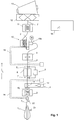
- Fig. 1 shows a winding unit of a winder with a yarn source in the form of a cop 1 or a Kone. From this, the yarn 2 is unwound and guided to a first yarn brake 3, which imposes on the yarn 2 a desired, as constant as possible tension. The yarn then passes through a retraction device 4 to be described later, a cutting device 5 and a splicing device 6.
- the cutting device 5 has a first and a second cutting station 7, 8.
- the first cutting station 7, seen in the running direction L of the yarn 2 is arranged in front of the splicing device 6, ie it can cut the yarn in front of the splicing device 6.
- the second cutting station 8 is, viewed in the direction L of the yarn 2, arranged after the splicer 6, that is able to cut the yarn after the splicer.
- the yarn then passes through a yarn cleaner 9, which detects geometric defects or defects in the yarn in a manner known per se. This may be e.g. to thin or thick places or to act with foreign bodies.
- the yarn cleaner may e.g. work optically and / or capacitively.
- a yarn store 10 This is a continuous yarn store, which stores a certain length, for example at least 300 meters, of the running yarn in a wound or folded state. It is designed so that the stored yarn amount is so large that the defect removal process described below can be performed without having to interrupt the winding of the target coil.
- Suitable yarn storage of this type are, for example in EP 2 377 793 described.
- the yarn storage has a collection device 10a, with which the yarn is drawn from the yarn cleaner 9 ago.
- the yarn store is a cylinder or cone and onto which the yarn 2 is wound at the input end by means of a motor-driven rotating arm. At the exit end of the cylinder or cone, the yarn 2 is withdrawn by threading.
- the yarn 2 passes through a second yarn brake 11, to then be wound in the winding station via a roller 12 to the target coil 13.
- the target coil 13 is usually a cross-wound bobbin.
- the device can be designed as a grooved drum roller 12 also eliminated.
- the first suction tube 14 serves to capture yarn from the area of the winding machine in front of the splicing device 6 and bring it to the splicer 6, while the second suction tube 15 grips yarn from the area of the winding machine after the splicer 6 and brings it to the splicer 6.
- the processes in the device are controlled by a controller 16.
- This control can also be implemented in several parts, e.g. in the form of a control unit for the cleaner and a control unit for the winding unit.
- the already mentioned retraction device 4 is able to grasp the yarn in the area between the first yarn brake 3 and the splicer 6 and to exert on this a tensile force opposite to the direction L of the yarn and pull it back out of the yarn store 10.
- the retraction device 4 is equipped with a suction channel 17 which is connected to a vacuum source 18.
- the vacuum source 18 is activated, whereupon yarn is drawn into the suction channel 17.
- the retraction device can also be formed by the suction tube 14.
- a clamping device 19 which can be activated by the controller 16 can be seen in the running direction L in front of the retraction device 4 be provided, with which the yarn is held when the retraction device 4 is to be activated.
- the first threading of the yarn (eg at game start or game change) when the target coil is empty by first the yarn from the yarn source 1 manually or with external doffer (spool case) is guided to the target coil 13 and fixed there and then the take-up of the buffer 10, the thread automatically retracts and the Garnreserve already forms before the start of the target coil 13. Then, the roller 12 is driven to rotate and the winding operation on the target spool 13 begins.
- the yarn 2 passes through the winder in the manner described above.
- the yarn is unwound from Kops 1 and wound onto the target coil 13.
- the target spool 13 is full, it is replaced - manually or by means of a spool case - and the end of the yarn is applied to the new cone.
- the emptying of the yarn source 1 or the cop is advantageously detected early by a special head sensor 21, and further, a thread monitor 22 may be provided after the cop 1, so that a precise stop performed and the yarn end can be stopped below the splicer 6.
- the yarn beginning of the new cop is then guided to the output of the splicer 6 and spliced to the "old" end.
- the running through the yarn cleaner 9 yarn 2 is constantly monitored for yarn defects in normal operation. If a yarn defect is detected, the yarn, after the defect has completely passed the yarn cleaner 9, in the area between yarn source or cop 1 and Garn Equipment 10 stopped, for example by the retraction device 10a of the yarn storage 10 is stopped or even operated in the opposite direction. Since the speed of the yarn in normal operation is very high (up to, for example, 30 m / s), the defect will usually run into the yarn store 10 before the yarn comes to a complete stop.
- the retractor 4 is activated by the controller 16, and it starts pulling the yarn back through the yarn cleaner 9 in the direction of running L.
- the yarn is withdrawn slower against the direction L than that it is conveyed during the winding in the direction L, so that in Garnrlick 9 a more accurate measurement can take place to determine length, position and nature of the error exactly.
- the device may have a length measuring device in order to determine the path length of the withdrawn yarn.
- the retraction device may be configured such that the length of the retracted yarn is a known function of time and / or the control signals provided to the retraction device.
- the retraction device 10a of the yarn store 10 is switched on again and normal operation is resumed.
- the yarn is pulled back so far that seen in the direction L, front (ie leading in normal operation) end of the defect reaches the cutting station 7 in front of the splicer 6 , Then, the cutting station 7 is activated and the yarn is cut in the running direction L, before the defect.
- the end of the yarn 2 coming from the yarn store 10 remains in the splicer 6, while the other end, which still contains the defect, for example, detected by the suction tube 14 and backwards (ie toward the target coil 13) is moved, so that a yarn area, which, seen in the direction L, is located in front of the defect in the region of the cutting station 8 after the Splicing device 6 comes to rest.
- the cutting station 7 is activated again cut the yarn, whereby the defect can be cut out and removed, for example by means of a suitable suction device.
- the splicing device 6 splices the two yarn ends and the normal operation can be resumed.
- the winding process can continue to run on the target spool 13 during the removal of the defect, and the productivity of the winding machine can be maintained unabated.
- the winding machine shown is also able to repair yarn breaks automatically.
- an automaton e.g., suction arm 15, or if it is too short, another tool
- the yarn in the yarn store 10 will e.g. sucked from the retraction device 4 so far that its end just above the splice device 6 comes to rest. Then the yarn can be spliced. The yarn can then be rewound onto the buffer 10, whereupon the normal operation is restarted.
- the withdrawal device 4 is thus configured as a second yarn store, in addition to the first yarn store 10. This second yarn store can be made so large that it is able to receive all the yarn from the first yarn store 10.
- the yarn in the yarn store 10 may also be rejected, for example in the event that the retraction device 4 is not designed as a (sufficiently large) yarn store.
- the yarn source 1 used in the embodiments described above is a cop.
- the yarn source may be e.g. also be formed by an open-end spinning device.
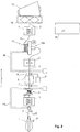
- the retraction device 4 is designed pneumatically. However, it is also conceivable that it is designed as a continuous yarn storage, as in Fig. 2 is pictured. In this case, the retraction device 4 is similar to the yarn storage 10 configured as a bobbin on which yarn is wound in normal operation from the lower end and unwound from the upper end. To retract yarn this is wound from the top.
- the yarn 2 is tested for defects with a yarn cleaner 9.
- the yarn 2 is first withdrawn by the yarn cleaner 9, wherein the yarn is checked again in more detail. Then the defect is cut out on the withdrawn yarn, whereupon the yarn 2 can be spliced again.
Landscapes
- Engineering & Computer Science (AREA)
- Textile Engineering (AREA)
- Quality & Reliability (AREA)
- Filamentary Materials, Packages, And Safety Devices Therefor (AREA)
- Replacing, Conveying, And Pick-Finding For Filamentary Materials (AREA)
Priority Applications (2)
| Application Number | Priority Date | Filing Date | Title |
|---|---|---|---|
| EP13001166.1A EP2774883B1 (de) | 2013-03-08 | 2013-03-08 | Verfahren zum Spulen und Reinigen eines Garns |
| JP2014045091A JP6333001B2 (ja) | 2013-03-08 | 2014-03-07 | 糸の巻き取り及び洗浄方法 |
Applications Claiming Priority (1)
| Application Number | Priority Date | Filing Date | Title |
|---|---|---|---|
| EP13001166.1A EP2774883B1 (de) | 2013-03-08 | 2013-03-08 | Verfahren zum Spulen und Reinigen eines Garns |
Publications (2)
| Publication Number | Publication Date |
|---|---|
| EP2774883A1 EP2774883A1 (de) | 2014-09-10 |
| EP2774883B1 true EP2774883B1 (de) | 2016-06-08 |
Family
ID=47891349
Family Applications (1)
| Application Number | Title | Priority Date | Filing Date |
|---|---|---|---|
| EP13001166.1A Active EP2774883B1 (de) | 2013-03-08 | 2013-03-08 | Verfahren zum Spulen und Reinigen eines Garns |
Country Status (2)
| Country | Link |
|---|---|
| EP (1) | EP2774883B1 (enExample) |
| JP (1) | JP6333001B2 (enExample) |
Families Citing this family (4)
| Publication number | Priority date | Publication date | Assignee | Title |
|---|---|---|---|---|
| JP2016050059A (ja) * | 2014-08-29 | 2016-04-11 | 村田機械株式会社 | 糸巻取装置、糸継方法及び糸継ユニット |
| JP2016102005A (ja) * | 2014-11-28 | 2016-06-02 | 村田機械株式会社 | 糸継装置、糸巻取機及び糸継方法 |
| JP2018154432A (ja) * | 2017-03-16 | 2018-10-04 | 村田機械株式会社 | クリアリングリミット設定装置、及び糸巻取機 |
| CN110304493A (zh) * | 2019-07-03 | 2019-10-08 | 安徽宏润工业设备安装有限公司 | 一种纱线卷绕装置 |
Family Cites Families (9)
| Publication number | Priority date | Publication date | Assignee | Title |
|---|---|---|---|---|
| AT244814B (de) * | 1963-08-14 | 1966-01-25 | Elitex Zavody Textilniho | Verfahren und Vorrichtung zur Herstellung eines Garnvorrates beim Garnspulen |
| JP3159120B2 (ja) * | 1997-05-09 | 2001-04-23 | 村田機械株式会社 | 自動ワインダー |
| EP1238937B1 (de) * | 2001-03-05 | 2004-08-18 | Gebrüder Loepfe AG | Verfahren und Vorrichtung zur Garnreinigung durch Herausschneiden von Fehlstellen |
| EP1828040B1 (de) * | 2004-12-01 | 2013-08-28 | Oerlikon Textile GmbH & Co. KG | Arbeitsstelle einer spulmaschine |
| ITUD20050142A1 (it) * | 2005-09-14 | 2007-03-15 | Sergio Zamattio | Metodo e dispositivo di roccatura di un filato e corpo avvolto cosi' realizzato |
| JP5007826B2 (ja) * | 2008-03-31 | 2012-08-22 | 村田機械株式会社 | 糸巻取装置及びこの糸巻取装置を備える自動ワインダ |
| JP2010047407A (ja) * | 2008-08-25 | 2010-03-04 | Murata Machinery Ltd | 糸巻取装置及びそれを備える自動ワインダ |
| CN102548884B (zh) * | 2009-09-30 | 2016-03-16 | 村田机械株式会社 | 纱线卷绕装置 |
| JP5365698B2 (ja) * | 2009-09-30 | 2013-12-11 | 村田機械株式会社 | 糸巻取装置 |
-
2013
- 2013-03-08 EP EP13001166.1A patent/EP2774883B1/de active Active
-
2014
- 2014-03-07 JP JP2014045091A patent/JP6333001B2/ja active Active
Non-Patent Citations (1)
| Title |
|---|
| None * |
Also Published As
| Publication number | Publication date |
|---|---|
| JP2014172759A (ja) | 2014-09-22 |
| EP2774883A1 (de) | 2014-09-10 |
| JP6333001B2 (ja) | 2018-05-30 |
Similar Documents
| Publication | Publication Date | Title |
|---|---|---|
| EP3052416B1 (de) | Garnreiniger sowie damit ausgerüstete spinnstelle einer spinnmaschine sowie verfahren zum betrieb einer spinnstelle | |
| DE102012016853A1 (de) | Verfahren zum Verbinden eines Ober- und Unterfadens an einer Arbeitsstelle einer Spulmaschine und Arbeitsstelle einer Spulmaschine | |
| EP2774883B1 (de) | Verfahren zum Spulen und Reinigen eines Garns | |
| DE102012016854A1 (de) | Verfahren zum Verbinden eines Ober- und Unterfadens an einer Arbeitsstelle einer Spulmaschine und Arbeitsstelle einer Spulmaschine | |
| DE19905860A1 (de) | Verfahren zum Betreiben einer Arbeitsstelle einer Kreuzspulen herstellenden Textilmaschine | |
| DE102015004261A1 (de) | Verfahren zum Betreiben eines Verbundsystems aus mindestens einer Ringspinnmaschine und mindestens einer Spulmaschine sowie Verbundsystem | |
| CH714064B1 (de) | Vorrichtung zur Ausreinigung von Garnfehlern aus einem Garn. | |
| EP2952462A1 (de) | Verfahren und vorrichtung zur überwachung der leerhülsenqualität | |
| EP1151951B1 (de) | Verfahren zum Betreiben einer Kreuzspulen herstellenden Textilmaschine | |
| DE4222377C2 (de) | Verfahren und Vorrichtung zum Erfassen eines auf einer Kreuzspule angeordneten Fadenendes | |
| DE102005029937B4 (de) | Verfahren zur Ermittlung der Qualitätsparameter eines Fadens | |
| EP3511275A1 (de) | Verfahren zum automatischen ansetzen eines fadens an einer arbeitsstelle einer textilmaschine sowie textilmaschine | |
| EP1076123B1 (de) | Verfahren und Vorrichtung zum Zentrifugenspinnen | |
| DE10239334A1 (de) | Fadenspulmaschine mit einem Spannungsdetektor | |
| EP1828040B1 (de) | Arbeitsstelle einer spulmaschine | |
| DE102015000570A1 (de) | Verfahren und Vorrichtung zum Bewerten der Spleißverbindungen | |
| EP0360287B1 (de) | Kopsvorbereitungsstation | |
| DE102014215599A1 (de) | Garnwickelmaschine und garnwickelverfahren | |
| EP1235071A1 (de) | Verfahren zum Prüfen der Reiss- und/oder Dehnungseigenschaften eines Garns | |
| DE10256293B4 (de) | Verfahren und Vorrichtung zum Betreiben einer Arbeitsstelle einer Kreuzspulen herstellenden Textilmaschine | |
| DE102019107712A1 (de) | Verfahren zum Herstellen einer Spleißverbindung an einer Arbeitsstelle einer Textilmaschine sowie Arbeitstelle einer Textilmaschine | |
| EP1238937A1 (de) | Verfahren und Vorrichtung zur Garnreinigung durch Herausschneiden von Fehlstellen | |
| DE102020130887A1 (de) | Verfahren zur Ermittlung des Gewichts einer Kreuzspule | |
| DE102020102801A1 (de) | Verfahren zur Drehzahlsteuerung einer Spulmaschine bei der Oberfadensuche | |
| EP4001193B1 (de) | Verfahren zur ermittlung des gewichts einer kreuzspule |
Legal Events
| Date | Code | Title | Description |
|---|---|---|---|
| PUAI | Public reference made under article 153(3) epc to a published international application that has entered the european phase |
Free format text: ORIGINAL CODE: 0009012 |
|
| 17P | Request for examination filed |
Effective date: 20130308 |
|
| AK | Designated contracting states |
Kind code of ref document: A1 Designated state(s): AL AT BE BG CH CY CZ DE DK EE ES FI FR GB GR HR HU IE IS IT LI LT LU LV MC MK MT NL NO PL PT RO RS SE SI SK SM TR |
|
| AX | Request for extension of the european patent |
Extension state: BA ME |
|
| R17P | Request for examination filed (corrected) |
Effective date: 20150221 |
|
| RBV | Designated contracting states (corrected) |
Designated state(s): AL AT BE BG CH CY CZ DE DK EE ES FI FR GB GR HR HU IE IS IT LI LT LU LV MC MK MT NL NO PL PT RO RS SE SI SK SM TR |
|
| 17Q | First examination report despatched |
Effective date: 20151203 |
|
| GRAP | Despatch of communication of intention to grant a patent |
Free format text: ORIGINAL CODE: EPIDOSNIGR1 |
|
| INTG | Intention to grant announced |
Effective date: 20160216 |
|
| GRAS | Grant fee paid |
Free format text: ORIGINAL CODE: EPIDOSNIGR3 |
|
| GRAA | (expected) grant |
Free format text: ORIGINAL CODE: 0009210 |
|
| AK | Designated contracting states |
Kind code of ref document: B1 Designated state(s): AL AT BE BG CH CY CZ DE DK EE ES FI FR GB GR HR HU IE IS IT LI LT LU LV MC MK MT NL NO PL PT RO RS SE SI SK SM TR |
|
| REG | Reference to a national code |
Ref country code: GB Ref legal event code: FG4D Free format text: NOT ENGLISH |
|
| REG | Reference to a national code |
Ref country code: CH Ref legal event code: EP Ref country code: CH Ref legal event code: NV Representative=s name: E. BLUM AND CO. AG PATENT- UND MARKENANWAELTE , CH |
|
| REG | Reference to a national code |
Ref country code: IE Ref legal event code: FG4D Free format text: LANGUAGE OF EP DOCUMENT: GERMAN |
|
| REG | Reference to a national code |
Ref country code: AT Ref legal event code: REF Ref document number: 805076 Country of ref document: AT Kind code of ref document: T Effective date: 20160715 |
|
| REG | Reference to a national code |
Ref country code: DE Ref legal event code: R096 Ref document number: 502013003296 Country of ref document: DE |
|
| REG | Reference to a national code |
Ref country code: LT Ref legal event code: MG4D |
|
| REG | Reference to a national code |
Ref country code: NL Ref legal event code: MP Effective date: 20160608 |
|
| PG25 | Lapsed in a contracting state [announced via postgrant information from national office to epo] |
Ref country code: FI Free format text: LAPSE BECAUSE OF FAILURE TO SUBMIT A TRANSLATION OF THE DESCRIPTION OR TO PAY THE FEE WITHIN THE PRESCRIBED TIME-LIMIT Effective date: 20160608 Ref country code: LT Free format text: LAPSE BECAUSE OF FAILURE TO SUBMIT A TRANSLATION OF THE DESCRIPTION OR TO PAY THE FEE WITHIN THE PRESCRIBED TIME-LIMIT Effective date: 20160608 Ref country code: NO Free format text: LAPSE BECAUSE OF FAILURE TO SUBMIT A TRANSLATION OF THE DESCRIPTION OR TO PAY THE FEE WITHIN THE PRESCRIBED TIME-LIMIT Effective date: 20160908 |
|
| PG25 | Lapsed in a contracting state [announced via postgrant information from national office to epo] |
Ref country code: RS Free format text: LAPSE BECAUSE OF FAILURE TO SUBMIT A TRANSLATION OF THE DESCRIPTION OR TO PAY THE FEE WITHIN THE PRESCRIBED TIME-LIMIT Effective date: 20160608 Ref country code: ES Free format text: LAPSE BECAUSE OF FAILURE TO SUBMIT A TRANSLATION OF THE DESCRIPTION OR TO PAY THE FEE WITHIN THE PRESCRIBED TIME-LIMIT Effective date: 20160608 Ref country code: LV Free format text: LAPSE BECAUSE OF FAILURE TO SUBMIT A TRANSLATION OF THE DESCRIPTION OR TO PAY THE FEE WITHIN THE PRESCRIBED TIME-LIMIT Effective date: 20160608 Ref country code: GR Free format text: LAPSE BECAUSE OF FAILURE TO SUBMIT A TRANSLATION OF THE DESCRIPTION OR TO PAY THE FEE WITHIN THE PRESCRIBED TIME-LIMIT Effective date: 20160909 Ref country code: NL Free format text: LAPSE BECAUSE OF FAILURE TO SUBMIT A TRANSLATION OF THE DESCRIPTION OR TO PAY THE FEE WITHIN THE PRESCRIBED TIME-LIMIT Effective date: 20160608 Ref country code: SE Free format text: LAPSE BECAUSE OF FAILURE TO SUBMIT A TRANSLATION OF THE DESCRIPTION OR TO PAY THE FEE WITHIN THE PRESCRIBED TIME-LIMIT Effective date: 20160608 Ref country code: HR Free format text: LAPSE BECAUSE OF FAILURE TO SUBMIT A TRANSLATION OF THE DESCRIPTION OR TO PAY THE FEE WITHIN THE PRESCRIBED TIME-LIMIT Effective date: 20160608 |
|
| PG25 | Lapsed in a contracting state [announced via postgrant information from national office to epo] |
Ref country code: IS Free format text: LAPSE BECAUSE OF FAILURE TO SUBMIT A TRANSLATION OF THE DESCRIPTION OR TO PAY THE FEE WITHIN THE PRESCRIBED TIME-LIMIT Effective date: 20161008 Ref country code: RO Free format text: LAPSE BECAUSE OF FAILURE TO SUBMIT A TRANSLATION OF THE DESCRIPTION OR TO PAY THE FEE WITHIN THE PRESCRIBED TIME-LIMIT Effective date: 20160608 Ref country code: EE Free format text: LAPSE BECAUSE OF FAILURE TO SUBMIT A TRANSLATION OF THE DESCRIPTION OR TO PAY THE FEE WITHIN THE PRESCRIBED TIME-LIMIT Effective date: 20160608 Ref country code: SK Free format text: LAPSE BECAUSE OF FAILURE TO SUBMIT A TRANSLATION OF THE DESCRIPTION OR TO PAY THE FEE WITHIN THE PRESCRIBED TIME-LIMIT Effective date: 20160608 |
|
| PG25 | Lapsed in a contracting state [announced via postgrant information from national office to epo] |
Ref country code: PL Free format text: LAPSE BECAUSE OF FAILURE TO SUBMIT A TRANSLATION OF THE DESCRIPTION OR TO PAY THE FEE WITHIN THE PRESCRIBED TIME-LIMIT Effective date: 20160608 Ref country code: SM Free format text: LAPSE BECAUSE OF FAILURE TO SUBMIT A TRANSLATION OF THE DESCRIPTION OR TO PAY THE FEE WITHIN THE PRESCRIBED TIME-LIMIT Effective date: 20160608 Ref country code: PT Free format text: LAPSE BECAUSE OF FAILURE TO SUBMIT A TRANSLATION OF THE DESCRIPTION OR TO PAY THE FEE WITHIN THE PRESCRIBED TIME-LIMIT Effective date: 20161010 |
|
| REG | Reference to a national code |
Ref country code: DE Ref legal event code: R097 Ref document number: 502013003296 Country of ref document: DE |
|
| PLBE | No opposition filed within time limit |
Free format text: ORIGINAL CODE: 0009261 |
|
| STAA | Information on the status of an ep patent application or granted ep patent |
Free format text: STATUS: NO OPPOSITION FILED WITHIN TIME LIMIT |
|
| 26N | No opposition filed |
Effective date: 20170309 |
|
| PG25 | Lapsed in a contracting state [announced via postgrant information from national office to epo] |
Ref country code: SI Free format text: LAPSE BECAUSE OF FAILURE TO SUBMIT A TRANSLATION OF THE DESCRIPTION OR TO PAY THE FEE WITHIN THE PRESCRIBED TIME-LIMIT Effective date: 20160608 Ref country code: DK Free format text: LAPSE BECAUSE OF FAILURE TO SUBMIT A TRANSLATION OF THE DESCRIPTION OR TO PAY THE FEE WITHIN THE PRESCRIBED TIME-LIMIT Effective date: 20160608 |
|
| GBPC | Gb: european patent ceased through non-payment of renewal fee |
Effective date: 20170308 |
|
| PG25 | Lapsed in a contracting state [announced via postgrant information from national office to epo] |
Ref country code: MC Free format text: LAPSE BECAUSE OF FAILURE TO SUBMIT A TRANSLATION OF THE DESCRIPTION OR TO PAY THE FEE WITHIN THE PRESCRIBED TIME-LIMIT Effective date: 20160608 |
|
| REG | Reference to a national code |
Ref country code: IE Ref legal event code: MM4A |
|
| REG | Reference to a national code |
Ref country code: FR Ref legal event code: ST Effective date: 20171130 |
|
| PG25 | Lapsed in a contracting state [announced via postgrant information from national office to epo] |
Ref country code: FR Free format text: LAPSE BECAUSE OF NON-PAYMENT OF DUE FEES Effective date: 20170331 Ref country code: LU Free format text: LAPSE BECAUSE OF NON-PAYMENT OF DUE FEES Effective date: 20170308 |
|
| PG25 | Lapsed in a contracting state [announced via postgrant information from national office to epo] |
Ref country code: IE Free format text: LAPSE BECAUSE OF NON-PAYMENT OF DUE FEES Effective date: 20170308 Ref country code: GB Free format text: LAPSE BECAUSE OF NON-PAYMENT OF DUE FEES Effective date: 20170308 |
|
| REG | Reference to a national code |
Ref country code: BE Ref legal event code: MM Effective date: 20170331 |
|
| PG25 | Lapsed in a contracting state [announced via postgrant information from national office to epo] |
Ref country code: BE Free format text: LAPSE BECAUSE OF NON-PAYMENT OF DUE FEES Effective date: 20170331 |
|
| PG25 | Lapsed in a contracting state [announced via postgrant information from national office to epo] |
Ref country code: MT Free format text: LAPSE BECAUSE OF FAILURE TO SUBMIT A TRANSLATION OF THE DESCRIPTION OR TO PAY THE FEE WITHIN THE PRESCRIBED TIME-LIMIT Effective date: 20160608 |
|
| PG25 | Lapsed in a contracting state [announced via postgrant information from national office to epo] |
Ref country code: AL Free format text: LAPSE BECAUSE OF FAILURE TO SUBMIT A TRANSLATION OF THE DESCRIPTION OR TO PAY THE FEE WITHIN THE PRESCRIBED TIME-LIMIT Effective date: 20160608 |
|
| REG | Reference to a national code |
Ref country code: AT Ref legal event code: MM01 Ref document number: 805076 Country of ref document: AT Kind code of ref document: T Effective date: 20180308 |
|
| PG25 | Lapsed in a contracting state [announced via postgrant information from national office to epo] |
Ref country code: HU Free format text: LAPSE BECAUSE OF FAILURE TO SUBMIT A TRANSLATION OF THE DESCRIPTION OR TO PAY THE FEE WITHIN THE PRESCRIBED TIME-LIMIT; INVALID AB INITIO Effective date: 20130308 |
|
| PG25 | Lapsed in a contracting state [announced via postgrant information from national office to epo] |
Ref country code: BG Free format text: LAPSE BECAUSE OF FAILURE TO SUBMIT A TRANSLATION OF THE DESCRIPTION OR TO PAY THE FEE WITHIN THE PRESCRIBED TIME-LIMIT Effective date: 20160608 |
|
| PG25 | Lapsed in a contracting state [announced via postgrant information from national office to epo] |
Ref country code: AT Free format text: LAPSE BECAUSE OF NON-PAYMENT OF DUE FEES Effective date: 20180308 Ref country code: CY Free format text: LAPSE BECAUSE OF NON-PAYMENT OF DUE FEES Effective date: 20160608 |
|
| PG25 | Lapsed in a contracting state [announced via postgrant information from national office to epo] |
Ref country code: MK Free format text: LAPSE BECAUSE OF FAILURE TO SUBMIT A TRANSLATION OF THE DESCRIPTION OR TO PAY THE FEE WITHIN THE PRESCRIBED TIME-LIMIT Effective date: 20160608 |
|
| PG25 | Lapsed in a contracting state [announced via postgrant information from national office to epo] |
Ref country code: TR Free format text: LAPSE BECAUSE OF FAILURE TO SUBMIT A TRANSLATION OF THE DESCRIPTION OR TO PAY THE FEE WITHIN THE PRESCRIBED TIME-LIMIT Effective date: 20160608 |
|
| P01 | Opt-out of the competence of the unified patent court (upc) registered |
Effective date: 20230513 |
|
| PGFP | Annual fee paid to national office [announced via postgrant information from national office to epo] |
Ref country code: DE Payment date: 20250331 Year of fee payment: 13 |
|
| PGFP | Annual fee paid to national office [announced via postgrant information from national office to epo] |
Ref country code: CZ Payment date: 20250219 Year of fee payment: 13 |
|
| PGFP | Annual fee paid to national office [announced via postgrant information from national office to epo] |
Ref country code: IT Payment date: 20250327 Year of fee payment: 13 |
|
| PGFP | Annual fee paid to national office [announced via postgrant information from national office to epo] |
Ref country code: CH Payment date: 20250401 Year of fee payment: 13 |