EP2774883B1 - Method for winding and cleaning a yarn - Google Patents
Method for winding and cleaning a yarn Download PDFInfo
- Publication number
- EP2774883B1 EP2774883B1 EP13001166.1A EP13001166A EP2774883B1 EP 2774883 B1 EP2774883 B1 EP 2774883B1 EP 13001166 A EP13001166 A EP 13001166A EP 2774883 B1 EP2774883 B1 EP 2774883B1
- Authority
- EP
- European Patent Office
- Prior art keywords
- yarn
- defect
- cleaner
- detection
- cutting
- Prior art date
- Legal status (The legal status is an assumption and is not a legal conclusion. Google has not performed a legal analysis and makes no representation as to the accuracy of the status listed.)
- Active
Links
Images
Classifications
-
- B—PERFORMING OPERATIONS; TRANSPORTING
- B65—CONVEYING; PACKING; STORING; HANDLING THIN OR FILAMENTARY MATERIAL
- B65H—HANDLING THIN OR FILAMENTARY MATERIAL, e.g. SHEETS, WEBS, CABLES
- B65H51/00—Forwarding filamentary material
- B65H51/20—Devices for temporarily storing filamentary material during forwarding, e.g. for buffer storage
- B65H51/205—Devices for temporarily storing filamentary material during forwarding, e.g. for buffer storage by means of a fluid
-
- B—PERFORMING OPERATIONS; TRANSPORTING
- B65—CONVEYING; PACKING; STORING; HANDLING THIN OR FILAMENTARY MATERIAL
- B65H—HANDLING THIN OR FILAMENTARY MATERIAL, e.g. SHEETS, WEBS, CABLES
- B65H51/00—Forwarding filamentary material
- B65H51/20—Devices for temporarily storing filamentary material during forwarding, e.g. for buffer storage
- B65H51/22—Reels or cages, e.g. cylindrical, with storing and forwarding surfaces provided by rollers or bars
-
- B—PERFORMING OPERATIONS; TRANSPORTING
- B65—CONVEYING; PACKING; STORING; HANDLING THIN OR FILAMENTARY MATERIAL
- B65H—HANDLING THIN OR FILAMENTARY MATERIAL, e.g. SHEETS, WEBS, CABLES
- B65H54/00—Winding, coiling, or depositing filamentary material
- B65H54/70—Other constructional features of yarn-winding machines
- B65H54/71—Arrangements for severing filamentary materials
-
- B—PERFORMING OPERATIONS; TRANSPORTING
- B65—CONVEYING; PACKING; STORING; HANDLING THIN OR FILAMENTARY MATERIAL
- B65H—HANDLING THIN OR FILAMENTARY MATERIAL, e.g. SHEETS, WEBS, CABLES
- B65H63/00—Warning or safety devices, e.g. automatic fault detectors, stop-motions ; Quality control of the package
- B65H63/06—Warning or safety devices, e.g. automatic fault detectors, stop-motions ; Quality control of the package responsive to presence of irregularities in running material, e.g. for severing the material at irregularities ; Control of the correct working of the yarn cleaner
-
- B—PERFORMING OPERATIONS; TRANSPORTING
- B65—CONVEYING; PACKING; STORING; HANDLING THIN OR FILAMENTARY MATERIAL
- B65H—HANDLING THIN OR FILAMENTARY MATERIAL, e.g. SHEETS, WEBS, CABLES
- B65H69/00—Methods of, or devices for, interconnecting successive lengths of material; Knot-tying devices ;Control of the correct working of the interconnecting device
- B65H69/06—Methods of, or devices for, interconnecting successive lengths of material; Knot-tying devices ;Control of the correct working of the interconnecting device by splicing
-
- B—PERFORMING OPERATIONS; TRANSPORTING
- B65—CONVEYING; PACKING; STORING; HANDLING THIN OR FILAMENTARY MATERIAL
- B65H—HANDLING THIN OR FILAMENTARY MATERIAL, e.g. SHEETS, WEBS, CABLES
- B65H2701/00—Handled material; Storage means
- B65H2701/30—Handled filamentary material
- B65H2701/31—Textiles threads or artificial strands of filaments
Definitions
- the invention relates to a method of winding a yarn from a yarn source onto a target reel in a winder, the yarn being passed between the yarn source and the target reel through a yarn cleaner for yarn quality assurance.
- the invention further relates to a winding machine with yarn cleaner.
- JP H10-310330 describes a yarn cleaner in which upon detection of a defect the yarn is cut. Then the yarn end is retrieved into the splitter, the faulty spot is completely cut out, the yarn ends are spliced, and the rewinding operation is resumed.
- EP 1 238 937 a yarn cleaning method in which, after detecting a single fault, the yarn is cut, the yarn end is retrieved, the flaw is cut out and the ends are then spliced.
- EP 1 764 333 describes a yarn cleaner in which, upon detection of yarn failure, the yarn is withdrawn from a yarn store by means of rollers disposed between the yarn cleaner and the yarn store. The yarn is then cut a first time.
- EP 2 377 793 describes a method and apparatus for winding yarn from a yarn source, eg from a cop, onto a target spool in the form of a cross-wound bobbin.
- the yarn passes through a yarn cleaner which detects defects in the composition and / or thickness of the yarn. When such a yarn defect occurs the yarn is cut behind the yarn fault. Then the yarn end with the yarn defect is sought by a specially provided for this purpose suction device behind the yarn cleaner, picked up and pulled back against the direction and shortened so far that the yarn defect is removed. Thereafter, the yarn ends thus formed can be spliced in a splicer.
- the yarn is thus guided by the yarn source in a direction through the yarn cleaner, which is detected upon detection of a yarn defect of the yarn defect and the yarn is then spliced.
- the yarn is first withdrawn against the direction of rotation and only then cut when detecting the yarn error. By retracting the still uncut yarn, searching for the yarn end behind the yarn cleaner is unnecessary.
- a tensile force is exerted on the yarn in the region between the yarn source and the yarn cleaner by means of a retraction device.
- steps a) and c) can be carried out almost simultaneously, and only after that steps b) and d).
- step b) and / or d) can also be carried out during the splicing process according to step e).
- the cutting according to steps b) and d) can also take place on opposite sides of the splicing device.
- the cutting device may have a first cutting station in the direction of travel in front of the splicing device and a second cutting station in the direction of travel after the splicing device.
- the yarn may be retracted counter to the direction of travel by the yarn cleaner while being measured by the yarn cleaner.
- the yarn error can be verified and / or its position can be determined more accurately, whereby yarn losses can be reduced.
- the yarn is advantageously withdrawn so far until the whole yarn defect has run back through the yarn cleaner.
- the yarn is retracted slower against the running direction upon detection of the yarn defect than that it is conveyed while winding in the running direction.
- This slower movement allows for a more accurate positioning of the yarn when cutting out the yarn defect, and if the yarn is rethreaded when retracted from the yarn cleaner, a more accurate measurement can be made, thus guaranteeing a higher yarn quality.
- the invention also relates to a winder for winding a yarn from a yarn source onto a target bobbin.
- the winder has a yarn cleaner for securing the yarn quality, a cutter for cutting out yarn defects, and a splicer for splicing the yarn. Further, between the yarn source and the yarn cleaner, it has a retreating device for applying a tensile force to the yarn to retract the yarn through the yarn cleaner in the direction opposite to the running direction upon detection of a yarn defect.
- a "withdrawal device arranged between the yarn source and the yarn cleaner” is meant a device which grasps and pulls the yarn on its path in the area between the yarn source and the yarn cleaner.
- the winder has a controller for performing the above-mentioned method.
- a first pass yarn store may be provided between the yarn cleaner and the target bobbin.
- Such a pass yarn store is capable of buffering a certain amount of the running yarn and allows the winding operation on the target bobbin continue while the yarn is being cleaned. This increases productivity compared to conventional winding machines.
- the retraction device can be designed as a second yarn store, in particular as a second pass yarn store.
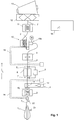
- Fig. 1 shows a winding unit of a winder with a yarn source in the form of a cop 1 or a Kone. From this, the yarn 2 is unwound and guided to a first yarn brake 3, which imposes on the yarn 2 a desired, as constant as possible tension. The yarn then passes through a retraction device 4 to be described later, a cutting device 5 and a splicing device 6.
- the cutting device 5 has a first and a second cutting station 7, 8.
- the first cutting station 7, seen in the running direction L of the yarn 2 is arranged in front of the splicing device 6, ie it can cut the yarn in front of the splicing device 6.
- the second cutting station 8 is, viewed in the direction L of the yarn 2, arranged after the splicer 6, that is able to cut the yarn after the splicer.
- the yarn then passes through a yarn cleaner 9, which detects geometric defects or defects in the yarn in a manner known per se. This may be e.g. to thin or thick places or to act with foreign bodies.
- the yarn cleaner may e.g. work optically and / or capacitively.
- a yarn store 10 This is a continuous yarn store, which stores a certain length, for example at least 300 meters, of the running yarn in a wound or folded state. It is designed so that the stored yarn amount is so large that the defect removal process described below can be performed without having to interrupt the winding of the target coil.
- Suitable yarn storage of this type are, for example in EP 2 377 793 described.
- the yarn storage has a collection device 10a, with which the yarn is drawn from the yarn cleaner 9 ago.
- the yarn store is a cylinder or cone and onto which the yarn 2 is wound at the input end by means of a motor-driven rotating arm. At the exit end of the cylinder or cone, the yarn 2 is withdrawn by threading.
- the yarn 2 passes through a second yarn brake 11, to then be wound in the winding station via a roller 12 to the target coil 13.
- the target coil 13 is usually a cross-wound bobbin.
- the device can be designed as a grooved drum roller 12 also eliminated.
- the first suction tube 14 serves to capture yarn from the area of the winding machine in front of the splicing device 6 and bring it to the splicer 6, while the second suction tube 15 grips yarn from the area of the winding machine after the splicer 6 and brings it to the splicer 6.
- the processes in the device are controlled by a controller 16.
- This control can also be implemented in several parts, e.g. in the form of a control unit for the cleaner and a control unit for the winding unit.
- the already mentioned retraction device 4 is able to grasp the yarn in the area between the first yarn brake 3 and the splicer 6 and to exert on this a tensile force opposite to the direction L of the yarn and pull it back out of the yarn store 10.
- the retraction device 4 is equipped with a suction channel 17 which is connected to a vacuum source 18.
- the vacuum source 18 is activated, whereupon yarn is drawn into the suction channel 17.
- the retraction device can also be formed by the suction tube 14.
- a clamping device 19 which can be activated by the controller 16 can be seen in the running direction L in front of the retraction device 4 be provided, with which the yarn is held when the retraction device 4 is to be activated.
- the first threading of the yarn (eg at game start or game change) when the target coil is empty by first the yarn from the yarn source 1 manually or with external doffer (spool case) is guided to the target coil 13 and fixed there and then the take-up of the buffer 10, the thread automatically retracts and the Garnreserve already forms before the start of the target coil 13. Then, the roller 12 is driven to rotate and the winding operation on the target spool 13 begins.
- the yarn 2 passes through the winder in the manner described above.
- the yarn is unwound from Kops 1 and wound onto the target coil 13.
- the target spool 13 is full, it is replaced - manually or by means of a spool case - and the end of the yarn is applied to the new cone.
- the emptying of the yarn source 1 or the cop is advantageously detected early by a special head sensor 21, and further, a thread monitor 22 may be provided after the cop 1, so that a precise stop performed and the yarn end can be stopped below the splicer 6.
- the yarn beginning of the new cop is then guided to the output of the splicer 6 and spliced to the "old" end.
- the running through the yarn cleaner 9 yarn 2 is constantly monitored for yarn defects in normal operation. If a yarn defect is detected, the yarn, after the defect has completely passed the yarn cleaner 9, in the area between yarn source or cop 1 and Garn Equipment 10 stopped, for example by the retraction device 10a of the yarn storage 10 is stopped or even operated in the opposite direction. Since the speed of the yarn in normal operation is very high (up to, for example, 30 m / s), the defect will usually run into the yarn store 10 before the yarn comes to a complete stop.
- the retractor 4 is activated by the controller 16, and it starts pulling the yarn back through the yarn cleaner 9 in the direction of running L.
- the yarn is withdrawn slower against the direction L than that it is conveyed during the winding in the direction L, so that in Garnrlick 9 a more accurate measurement can take place to determine length, position and nature of the error exactly.
- the device may have a length measuring device in order to determine the path length of the withdrawn yarn.
- the retraction device may be configured such that the length of the retracted yarn is a known function of time and / or the control signals provided to the retraction device.
- the retraction device 10a of the yarn store 10 is switched on again and normal operation is resumed.
- the yarn is pulled back so far that seen in the direction L, front (ie leading in normal operation) end of the defect reaches the cutting station 7 in front of the splicer 6 , Then, the cutting station 7 is activated and the yarn is cut in the running direction L, before the defect.
- the end of the yarn 2 coming from the yarn store 10 remains in the splicer 6, while the other end, which still contains the defect, for example, detected by the suction tube 14 and backwards (ie toward the target coil 13) is moved, so that a yarn area, which, seen in the direction L, is located in front of the defect in the region of the cutting station 8 after the Splicing device 6 comes to rest.
- the cutting station 7 is activated again cut the yarn, whereby the defect can be cut out and removed, for example by means of a suitable suction device.
- the splicing device 6 splices the two yarn ends and the normal operation can be resumed.
- the winding process can continue to run on the target spool 13 during the removal of the defect, and the productivity of the winding machine can be maintained unabated.
- the winding machine shown is also able to repair yarn breaks automatically.
- an automaton e.g., suction arm 15, or if it is too short, another tool
- the yarn in the yarn store 10 will e.g. sucked from the retraction device 4 so far that its end just above the splice device 6 comes to rest. Then the yarn can be spliced. The yarn can then be rewound onto the buffer 10, whereupon the normal operation is restarted.
- the withdrawal device 4 is thus configured as a second yarn store, in addition to the first yarn store 10. This second yarn store can be made so large that it is able to receive all the yarn from the first yarn store 10.
- the yarn in the yarn store 10 may also be rejected, for example in the event that the retraction device 4 is not designed as a (sufficiently large) yarn store.
- the yarn source 1 used in the embodiments described above is a cop.
- the yarn source may be e.g. also be formed by an open-end spinning device.
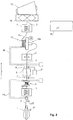
- the retraction device 4 is designed pneumatically. However, it is also conceivable that it is designed as a continuous yarn storage, as in Fig. 2 is pictured. In this case, the retraction device 4 is similar to the yarn storage 10 configured as a bobbin on which yarn is wound in normal operation from the lower end and unwound from the upper end. To retract yarn this is wound from the top.
- the yarn 2 is tested for defects with a yarn cleaner 9.
- the yarn 2 is first withdrawn by the yarn cleaner 9, wherein the yarn is checked again in more detail. Then the defect is cut out on the withdrawn yarn, whereupon the yarn 2 can be spliced again.
Description
Die Erfindung betrifft ein Verfahren zum Spulen eines Garns von einer Garnquelle auf eine Zielspule in einer Spulmaschine, wobei das Garn zwischen der Garnquelle und der Zielspule durch einen Garnreiniger zur Sicherung der Garnqualität geführt wird. Die Erfindung betrifft weiter eine Spulmaschine mit Garnreiniger.The invention relates to a method of winding a yarn from a yarn source onto a target reel in a winder, the yarn being passed between the yarn source and the target reel through a yarn cleaner for yarn quality assurance. The invention further relates to a winding machine with yarn cleaner.
Ebenso beschreibt
Das Suchen der Garnenden mit unbekannter Position nimmt dabei beträchtliche Zeit in Anspruch und führt zu einer Reduktion der Produktivität.Searching the yarn ends with unknown position takes considerable time and leads to a reduction in productivity.
Es ist Aufgabe der vorliegenden Erfindung, ein Verfahren sowie eine Spulmaschine der eingangs genannten Art bereitzustellen, bei denen das Herausschneiden eines Garnfehlers in einfacher und ökonomischer Art realisiert werden kann.It is an object of the present invention to provide a method and a winder of the type mentioned, in which the cutting out of a yarn defect can be realized in a simple and economical manner.
Diese Aufgabe wird vom Gegenstand der unabhängigen Ansprüche gelöst. Demgemäss wird das Garn also von der Garnquelle in einer Laufrichtung durch den Garnreiniger geführt, wobei bei Detektion eines Garnfehlers der Garnfehler herausgeschnitten und das Garn sodann verspleisst wird. Dabei wird jedoch bei der Detektion des Garnfehlers das Garn zunächst entgegen der Laufrichtung zurückgezogen und erst dann geschnitten. Indem das noch ungeschnittene Garn zurückgezogen wird, erübrigt sich das Suchen des Garnendes hinter dem Garnreiniger.This object is solved by the subject matter of the independent claims. Accordingly, the yarn is thus guided by the yarn source in a direction through the yarn cleaner, which is detected upon detection of a yarn defect of the yarn defect and the yarn is then spliced. In this case, however, the yarn is first withdrawn against the direction of rotation and only then cut when detecting the yarn error. By retracting the still uncut yarn, searching for the yarn end behind the yarn cleaner is unnecessary.
Zum Zurückziehen des Garns wird im Bereich zwischen der Garnquelle und dem Garnreiniger mittels einer Rückzugsvorrichtung eine Zugkraft auf das Garn ausgeübt.To retract the yarn, a tensile force is exerted on the yarn in the region between the yarn source and the yarn cleaner by means of a retraction device.
In einer vorteilhaften Ausführung durchläuft das Verfahren bei der Detektion des Garnfehlers die folgenden Schritte:
- a) Zurückziehen des Garns soweit, dass ein erster Endbereich des Garnfehlers im Bereich einer Schneidevorrichtung zu liegen kommt;
- b) Schneiden des Garns mit der Schneidevorrichtung zum Erzeugen eines ersten Garnendes;
- c) Positionieren des den Garnfehler aufweisenden Garnabschnitts derart, dass ein zweiter Endbereich des Garnfehlers im Bereich der Schneidevorrichtung zu liegen kommt;
- d) Schneiden des Garns mit der Schneidevorrichtung zum Erzeugen eines zweiten Garnendes; und
- e) Verspleissen des ersten Garnendes und des zweiten Garnendes.
- a) retraction of the yarn to the extent that a first end region of the yarn defect comes to lie in the region of a cutting device;
- b) cutting the yarn with the cutting device to produce a first yarn end;
- c) positioning the yarn section having the yarn fault such that a second end area of the yarn fault comes to rest in the region of the cutting device;
- d) cutting the yarn with the cutting device to produce a second yarn end; and
- e) Splicing the first yarn end and the second yarn end.
Die Reihenfolge dieser Schritte ist grundsätzlich beliebig. Insbesondere können die Schritte a) und c) fast gleichzeitig erfolgen, und erst danach die Schritte b) und d).The order of these steps is basically arbitrary. In particular, steps a) and c) can be carried out almost simultaneously, and only after that steps b) and d).
Weiter kann das Schneiden gemäss Schritt b) und/oder d) auch während des Spleissprozesses gemäss Schritt e) durchgeführt werden.Furthermore, the cutting according to step b) and / or d) can also be carried out during the splicing process according to step e).
Das Schneiden gemäss Schritt b) und d) kann auch auf gegenüber liegenden Seiten der Spleissvorrichtung erfolgen. Hierzu kann die Schneidevorrichtung eine erste Schneidestation in Laufrichtung vor der Spleissvorrichtung und eine zweite Schneidestation in Laufrichtung nach der Spleissvorrichtung aufweisen.The cutting according to steps b) and d) can also take place on opposite sides of the splicing device. For this purpose, the cutting device may have a first cutting station in the direction of travel in front of the splicing device and a second cutting station in the direction of travel after the splicing device.
Bei Detektion des Garnfehlers, kann das Garn entgegen der Laufrichtung durch den Garnreiniger zurückgezogen werden, während es vom Garnreiniger ausgemessen wird. Dabei kann der Garnfehler verifiziert und/oder dessen Position kann genauer bestimmt werden, wodurch Garnverluste reduziert werden können.Upon detection of the yarn failure, the yarn may be retracted counter to the direction of travel by the yarn cleaner while being measured by the yarn cleaner. In this case, the yarn error can be verified and / or its position can be determined more accurately, whereby yarn losses can be reduced.
Das Garn wird vorteilhaft soweit zurückgezogen, bis der ganze Garnfehler durch den Garnreiniger zurückgelaufen ist.The yarn is advantageously withdrawn so far until the whole yarn defect has run back through the yarn cleaner.
Vorteilhaft wird das Garn bei Detektion des Garnfehlers langsamer entgegen der Laufrichtung zurückgezogen als dass es beim Spulen in der Laufrichtung gefördert wird. Diese langsamere Bewegung erlaubt eine genauere Positionierung des Garns beim Herausschneiden des Garnfehlers, und, falls das Garn beim Zurückziehen vom Garnreiniger nochmals ausgemessen wird, kann eine genauere Messung durchgeführt und damit eine höhere Garnqualität garantiert werden.Advantageously, the yarn is retracted slower against the running direction upon detection of the yarn defect than that it is conveyed while winding in the running direction. This slower movement allows for a more accurate positioning of the yarn when cutting out the yarn defect, and if the yarn is rethreaded when retracted from the yarn cleaner, a more accurate measurement can be made, thus guaranteeing a higher yarn quality.
Die Erfindung betrifft auch eine Spulmaschine zum Spulen eines Garns von einer Garnquelle auf eine Zielspule.The invention also relates to a winder for winding a yarn from a yarn source onto a target bobbin.
Die Spulmaschine weist einen Garnreiniger zur Sicherung der Garnqualität, eine Schneidevorrichtung zum Herausschneiden von Garnfehlern und eine Spleissvorrichtung zum Spleissen des Garns auf. Weiter besitzt sie zwischen der Garnquelle und dem Garnreiniger eine Rückzugsvorrichtung zum Ausüben einer Zugkraft auf das Garn, um das Garn bei Detektion eines Garnfehlers entgegen der Laufrichtung durch den Garnreiniger zurückzuziehen. Unter einer "zwischen der Garnquelle und dem Garnreiniger" angeordneten Rückzugsvorrichtung ist dabei eine Vorrichtung zu verstehen, welche das Garn auf seinem Pfad im Bereich zwischen der Garnquelle und dem Garnreiniger erfasst und daran zieht.The winder has a yarn cleaner for securing the yarn quality, a cutter for cutting out yarn defects, and a splicer for splicing the yarn. Further, between the yarn source and the yarn cleaner, it has a retreating device for applying a tensile force to the yarn to retract the yarn through the yarn cleaner in the direction opposite to the running direction upon detection of a yarn defect. By a "withdrawal device arranged between the yarn source and the yarn cleaner" is meant a device which grasps and pulls the yarn on its path in the area between the yarn source and the yarn cleaner.
Die Spulmaschine weist eine Steuerung zum Durchführen des oben erwähnten Verfahrens auf.The winder has a controller for performing the above-mentioned method.
Zwischen dem Garnreiniger und der Zielspule kann ein erster Durchlauf-Garnspeicher vorgesehen sein. Ein derartiger Durchlauf-Garnspeicher ist in der Lage, eine gewisse Menge des laufenden Garns zwischenzuspeichern, und erlaubt es, den Aufspulvorgang auf die Zielspule fortzusetzen, während das Garn gereinigt wird. Das erhöht die Produktivität gegenüber konventionellen Spulmaschinen. Bei der Detektion des Garnfehlers mit der Rückzugsvorrichtung wird ein Teil des Garns entgegen der Laufrichtung aus dem Durchlauf-Garnspeicher zurückgezogen.A first pass yarn store may be provided between the yarn cleaner and the target bobbin. Such a pass yarn store is capable of buffering a certain amount of the running yarn and allows the winding operation on the target bobbin continue while the yarn is being cleaned. This increases productivity compared to conventional winding machines. Upon detection of the yarn failure with the retractor, a portion of the yarn is withdrawn from the pass yarn storage counter to the direction of travel.
Um das von der Rückzugsvorrichtung zurückgezogene Garn in geordneter Weise aufzunehmen, kann die Rückzugsvorrichtung als zweiter Garnspeicher, insbesondere als zweiter Durchlauf-Garnspeicher ausgestaltet werden.In order to receive the yarn withdrawn from the retraction device in an orderly manner, the retraction device can be designed as a second yarn store, in particular as a second pass yarn store.
Weitere Ausgestaltungen, Vorteile und Anwendungen der Erfindung ergeben sich aus den abhängigen Ansprüchen und aus der nun folgenden Beschreibung anhand der Figuren. Dabei zeigen:
-
Fig. 1 eine erste Ausführung einer Spulmaschine und -
Fig. 2 eine zweite Ausführung einer Spulmaschine.
-
Fig. 1 a first embodiment of a winder and -
Fig. 2 a second embodiment of a winder.
Sodann durchläuft das Garn einen Garnreiniger 9, welcher in an sich bekannter Weise geometrische oder inhaltliche Fehlstellen im Garn detektiert. Dabei kann es sich z.B. um Dünn- oder Dickstellen oder um Stellen mit Fremdfasern handeln. Der Garnreiniger kann z.B. optisch und/oder kapazitiv arbeiten.The yarn then passes through a
Nach dem Garnreiniger 9 gelangt das Garn zu einem Garnspeicher 10. Dabei handelt es sich um einen Durchlauf-Garnspeicher, der eine gewisse Länge, z.B. mindestens 300 Meter, des laufenden Garns in aufgewickeltem oder gefalteten Zustand speichert. Er ist so ausgestaltet, dass die gespeicherte Garnmenge so gross ist, dass der weiter unten beschriebene Prozess der Fehlstellenentfernung durchgeführt werden kann, ohne dass das Bewickeln der Zielspule unterbrochen werden muss. Geeignete Garnspeicher dieser Art sind z.B. in
Nach dem Garnspeicher 10 durchläuft das Garn 2 eine zweite Fadenbremse 11, um sodann in der Wickelstation über eine Walze 12 auf die Zielspule 13 aufgewickelt zu werden. Bei der Zielspule 13 handelt es sich üblicherweise um eine Kreuzspule. Je nach Konstruktion des Geräts kann die als Nutentrommel ausgestaltete Walze 12 auch entfallen.After the
Weiter besitzt die Spulmaschine gemäss
Die Abläufe im Gerät werden von einer Steuerung 16 gesteuert. Diese Steuerung kann auch mehrteilig ausgeführt sein, z.B. in Form einer Steuereinheit für den Reiniger und einer Steuereinheit für die Spulstelle.The processes in the device are controlled by a
Die bereits erwähnte Rückzugsvorrichtung 4 ist in der Lage, das Garn im Bereich zwischen der ersten Fadenbremse 3 und der Spleissvorrichtung 6 zu erfassen und auf dieses eine Zugkraft entgegen der Laufrichtung L des Garns auszuüben und es so aus dem Garnspeicher 10 zurück zu ziehen.The already mentioned
In der Ausführung nach
Um sicherzustellen, dass das Garn nur von Richtung des Garnspeichers 10 eingezogen wird, kann, in Laufrichtung L gesehen, vor der Rückzugsvorrichtung 4 eine von der Steuerung 16 aktivierbare Klemmvorrichtung 19 vorgesehen sein, mit welcher das Garn festgehalten wird, wenn die Rückzugsvorrichtung 4 aktiviert werden soll.In order to ensure that the yarn is drawn in only from the direction of the
Im Folgenden werden der Betrieb der Vorrichtung und die Schritte zum Entfernen eines Garnfehlers beschrieben.The operation of the apparatus and the steps for removing a yarn defect will be described below.
Das erste Einfädeln des Garns (z.B. bei Partiestart oder Partiewechsel) bei leerer Zielspule erfolgt, indem zunächst das Garn von der Garnquelle 1 manuell oder mit externem Doffer (Spulendoffer) zur Zielspule 13 geführt und dort fixiert wird und sodann der Aufwickelarm des Zwischenspeichers 10 den Faden automatisch einzieht und die Garnreserve bereits vor dem Anlaufen der Zielspule 13 bildet. Sodann wird die Walze 12 zur Drehung angetrieben und der Spulvorgang auf die Zielspule 13 beginnt.The first threading of the yarn (eg at game start or game change) when the target coil is empty by first the yarn from the
Im Normalbetrieb durchläuft das Garn 2 die Spulmaschine in der oben beschriebenen Weise. Dabei wird das Garn vom Kops 1 abgespult und auf die Zielspule 13 aufgewickelt.In normal operation, the
Ist die Zielspule 13 voll, so wird sie - manuell oder mittels Spulendoffer - ersetzt, und das das Garnende wird an die neue Kone angelegt.If the
Das Leerlaufen der Garnquelle 1 bzw. des Kops wird vorteilhaft von einem speziellen Kopssensor 21 frühzeitig erkannt, und weiter kann ein Fadenwächter 22 nach dem Kops 1 vorgesehen sein, so dass ein genauer Stopp durchgeführt und das Garnende unterhalb der Spleissvorrichtung 6 angehalten werden kann. Der Garnanfang des neuen Kops wird sodann bis zum Ausgang der Spleissvorrichtung 6 geführt und mit dem "alten" Ende verspleisst.The emptying of the
Das durch den Garnreiniger 9 laufende Garn 2 wird im Normalbetrieb dauernd auf Garnfehler überwacht. Wird ein Garnfehler festgestellt, so wird das Garn, nachdem die Fehlstelle den Garnreiniger 9 vollständig passiert hat, im Bereich zwischen Garnquelle bzw. Kops 1 und Garnspeicher 10 gestoppt, z.B. indem die Einzugsvorrichtung 10a des Garnspeichers 10 angehalten oder sogar in Gegenrichtung betrieben wird. Da die Geschwindigkeit des Garns im Normalbetrieb sehr hoch ist (bis z.B. 30 m/s), wird die Fehlstelle in der Regel bis in den Garnspeicher 10 laufen, bevor das Garn vollständig zum Stehen kommt.The running through the
Sodann wird, während die Zielspule weiter mit Garn aus dem Garnspeicher 10 bewickelt wird, von der Steuerung 16 die Rückzugsvorrichtung 4 aktiviert, und diese beginnt, das Garn entgegen der Laufrichtung L durch den Garnreiniger 9 zurückzuziehen. Dabei wird das Garn langsamer entgegen der Laufrichtung L zurückgezogen als dass es beim Spulen in Laufrichtung L gefördert wird, so dass im Garnreiniger 9 eine genauere Messung stattfinden kann, um Länge, Position und Art des Fehlers exakt zu bestimmen. Soll dabei eine genaue Längenmessung durchgeführt werden, so kann das Gerät eine Längenmessvorrichtung aufweisen, um die Weglänge des zurückgezogenen Garns zu bestimmen. Oder die Rückzugsvorrichtung kann so ausgestaltet sein, dass die Länge des zurückgezogenen Garns eine bekannte Funktion der Zeit und/oder der an die Rückzugsvorrichtung gelieferten Steuersignale ist.Then, while the target bobbin continues to be wound with yarn from the
Wird der so bestimmte Fehler als derart geringfügig eingestuft, dass er nicht entfernt werden muss, wird die Einzugsvorrichtung 10a des Garnspeichers 10 wieder eingeschaltet und der Normalbetrieb wieder aufgenommen.If the error thus determined is classified as such that it does not have to be removed, the
Wenn der Fehler als so gravierend eingestuft wird, dass die Fehlstelle entfernt werden muss, wird das Garn so weit zurückgezogen, dass das, in Laufrichtung L gesehen, vordere (d.h. im Normalbetrieb vorauslaufende) Ende der Fehlstelle bis zur Schneidestation 7 vor der Spleissvorrichtung 6 gelangt. Sodann wird die Schneidestation 7 aktiviert und das Garn wird, in Laufrichtung L gesehen, vor der Fehlstelle geschnitten. Das vom Garnspeicher 10 kommende Ende des Garns 2 verbleibt in der Spleissvorrichtung 6, während das andere Ende, welches noch die Fehlstelle enthält, z.B. vom Saugrohr 14 erfasst und nach hinten (d.h. in Richtung zur Zielspule 13 hin) bewegt wird, so dass ein Garnbereich, der, in Laufrichtung L gesehen, vor der Fehlstelle liegt, in den Bereich der Schneidestation 8 nach der Spleissvorrichtung 6 zu liegen kommt. Sodann wird die Schneidestation 7 aktiviert das Garn erneut geschnitten, wodurch die Fehlstelle herausgeschnitten und z.B. mittels einer geeigneten Saugvorrichtung entfernt werden kann. Nun verspleisst die Spleissvorrichtung 6 die beiden Garnenden und der Normalbetrieb kann wieder aufgenommen werden.If the error is classified as so serious that the defect must be removed, the yarn is pulled back so far that seen in the direction L, front (ie leading in normal operation) end of the defect reaches the cutting
Dank dem Garnspeicher 10 kann der Aufspulprozess auf die Zielspule 13 während der Entfernung der Fehlstelle weiterlaufen und die Produktivität der Spulmaschine unvermindert hoch gehalten werden.Thanks to the
Die dargestellte Spulmaschine ist auch in der Lage, Garnbrüche automatisch zu reparieren.The winding machine shown is also able to repair yarn breaks automatically.
Erfolgt ein Garnbruch zwischen der Zielspule 13 und dem Garnspeicher 10, so führt ein Automat (z.B. Saugarm 15 oder, falls dieser zu kurz ist, ein anderes Hilfsmittel) das Garnende von der Zielspule 13 zur Spleissvorrichtung 6. Das Garn im Garnspeicher 10 wird z.B. von der Rückzugsvorrichtung 4 soweit abgesaugt, dass dessen Ende knapp oberhalb der Spleissvorrichtung 6 zu liegen kommt. Sodann kann das Garn verspleisst werden. Das Garn kann danach wieder auf den Zwischenspeicher 10 aufgespult werden, worauf der Normalbetrieb wieder gestartet wird. In diesem Fall ist die Rückzugsvorrichtung 4 also als zweiter Garnspeicher, zusätzlich zum ersten Garnspeicher 10, ausgestaltet. Dieser zweite Garnspeicher kann so gross ausgestaltet sein, dass er in der Lage ist, alles Garn vom ersten Garnspeicher 10 aufzunehmen.If a yarn break occurs between the
Alternativ kann bei einem Garnbruch zwischen der Zielspule 13 und dem Garnspeicher 10 das Garn im Garnspeicher 10 auch verworfen werden, z.B. für den Fall, dass die Rückzugsvorrichtung 4 nicht als (ausreichend grosser) Garnspeicher ausgestaltet ist.Alternatively, in the event of yarn breakage between the
Bei einem Garnbruch zwischen der Spleissvorrichtung 6 und dem Garnspeicher 10 wird das Garnende mit dem Saugarm 15 vom Garnspeicher 10 zurück zur Spleissvorrichtung 6 geholt und dort verspleisst. Der Rest des Garns wird abgesaugt.In a yarn breakage between the
Bei einem Garnbruch zwischen der Garnquelle 1 und der Spleissvorrichtung 6 wird der Einzug von Garn in den Garnspeicher 10 gestoppt, das Garn wird mit dem Saugarm 14 von der Garnquelle zur Spleissvorrichtung 6 geholt und das Garn wird wieder verspleisst.In the event of yarn breakage between the
Als Garnquelle 1 dient in den oben beschriebenen Ausführungen ein Kops. Die Garnquelle kann jedoch z.B. auch von einer Open-End Spinnvorrichtung gebildet werden.The
In der Ausführung nach
Zusammenfassend kann gesagt werden, dass bei der beschriebenen Spulmaschine das Garn 2 mit einem Garnreiniger 9 auf Fehlstellen geprüft wird. Bei Detektion einer Fehlstelle wird das Garn 2 zunächst durch den Garnreiniger 9 zurückgezogen, wobei das Garn nochmals genauer geprüft wird. Sodann wird die Fehlstelle am zurückgezogenen Garn herausgeschnitten, worauf das Garn 2 wieder verspleisst werden kann.In summary, it can be said that in the winding machine described, the
Während in der vorliegenden Anmeldung bevorzugte Ausführungen der Erfindung beschrieben sind, ist klar darauf hinzuweisen, dass die Erfindung nicht auf diese beschränkt ist und in auch anderer Weise innerhalb des Umfangs der folgenden Ansprüche ausgeführt werden kann.While preferred embodiments of the invention are described in the present application, it should be clearly understood that the invention is not limited to these and may be practiced otherwise within the scope of the following claims.
Claims (12)
- Method for spooling a yarn from a yarn source (1) onto a target spool (13) in a spooling machine, wherein the yarn is guided between the yarn source (1) and the target spool (13) in a running direction (L) through a yarn cleaner (9) for ensuring yarn quality and wherein in case of detection of a yarn defect the yarn defect is cut out and thereafter the yarn is spliced, wherein in case of detection of the yarn defect the yarn is first pulled back against the running direction (L) and only after that it is cut off, characterized in that, in order to pull back the yarn in case of detection of the yarn defect, a tensile force is exerted on the yarn in an area between the yarn source (1) and the yarn cleaner (9) by means of a pull-back-device (4).
- Method according to claim 1, wherein in case of detection of the yarn defect the method has the following steps:a) pulling back the yarn to such extent that a first end section of the yarn defect comes to lie in the area of a cutting device (5),b) cutting the yarn with the cutting device (5) for generating a first yarn end,c) positioning the yarn section having the yarn defect in such a way that a second end section of the yarn defect comes to lie in the area of the cutting device (5),d) cutting the yarn with the cutting device (5) for generating a second yarn end ande) splicing the first yarn end and the second yarn end.
- Method according to claim 2, wherein the cutting according to step b) and d) is carried out on opposite sides of a splicing device of the spooling machine.
- Method according to one of the preceding claims, wherein a first throughput yarn accumulator (10) is provided between the yarn cleaner (9) and the target spool (13), wherein yarn from the throughput yarn accumulator (10) is pulled back against the running direction (L) in case of detection of the yarn defect.
- Method according to claim 4, wherein the throughput yarn accumulator (10) has a feed-in-device (10a) for pulling in the yarn coming from the yarn cleaner (9), wherein in case of detection of the yarn defect the feed-in-device (10a) is stopped or operated in opposite direction.
- Method according to one of the preceding claims, wherein in case of detection of the yarn defect the yarn is pulled back against the running direction (L) through the yarn cleaner (9), wherein during this process the yarn is measured in the yarn cleaner (9) in order to verify the yarn defect and/or to determine its position.
- Method according to one of the preceding claims, wherein the yarn is pulled back slower against the running direction (L) after detection of the yarn defect than while transporting it in running direction (L) during spooling.
- Method according to one of the preceding claims, wherein after detection of a yarn defect the yarn is pulled back to such extent that the entire yarn defect has passed through the yarn cleaner (9).
- Spooling machine for spooling a yarn from a yarn source (1) onto a target spool (13), wherein the spooling machine has a yarn cleaner (9) for ensuring the yarn quality, a cutting device (5) for cutting out yarn defects and a splicing device for splicing the yarn, characterized in that the spooling machine has a pull-back-device (4), between the yarn source (1) and the yarn cleaner (9), for exerting a tensile force onto the yarn in order to pull back the yarn through the yarn cleaner (9) against the running direction (L) in case of detection of the yarn defect, and in that the spooling machine has a controller for carrying out the method according to one of the preceding claims.
- Spooling machine according to claim 9, wherein the cutting device (5) has a first cutting station (7) before the splicing device in running direction (L) and a second cutting station (8) after the splicing device in running direction (L).
- Spooling machine according to one of the claims 9 or 10, with a first throughput yarn accumulator (10) arranged between the yarn cleaner (9) and the target spool (13), wherein in case of detection of the yarn defect a part of the yarn is pulled back out of the throughput yarn accumulator (10) against the running direction (L) by the pull-back-device (4).
- Spooling machine according to claim 11, wherein the pull-back-device (4) is formed as a second yarn accumulator, particularly as a second throughput yarn accumulator, for receiving the yarn pulled back by the pull-back-device (4).
Priority Applications (2)
| Application Number | Priority Date | Filing Date | Title |
|---|---|---|---|
| EP13001166.1A EP2774883B1 (en) | 2013-03-08 | 2013-03-08 | Method for winding and cleaning a yarn |
| JP2014045091A JP6333001B2 (en) | 2013-03-08 | 2014-03-07 | Thread winding and cleaning method |
Applications Claiming Priority (1)
| Application Number | Priority Date | Filing Date | Title |
|---|---|---|---|
| EP13001166.1A EP2774883B1 (en) | 2013-03-08 | 2013-03-08 | Method for winding and cleaning a yarn |
Publications (2)
| Publication Number | Publication Date |
|---|---|
| EP2774883A1 EP2774883A1 (en) | 2014-09-10 |
| EP2774883B1 true EP2774883B1 (en) | 2016-06-08 |
Family
ID=47891349
Family Applications (1)
| Application Number | Title | Priority Date | Filing Date |
|---|---|---|---|
| EP13001166.1A Active EP2774883B1 (en) | 2013-03-08 | 2013-03-08 | Method for winding and cleaning a yarn |
Country Status (2)
| Country | Link |
|---|---|
| EP (1) | EP2774883B1 (en) |
| JP (1) | JP6333001B2 (en) |
Families Citing this family (4)
| Publication number | Priority date | Publication date | Assignee | Title |
|---|---|---|---|---|
| JP2016050059A (en) * | 2014-08-29 | 2016-04-11 | 村田機械株式会社 | Yarn winding device, yarn piecing method, and yarn piecing unit |
| JP2016102005A (en) * | 2014-11-28 | 2016-06-02 | 村田機械株式会社 | Yarn splicing device, yarn winding machine and yarn splicing method |
| JP2018154432A (en) * | 2017-03-16 | 2018-10-04 | 村田機械株式会社 | Clearing limit setting device, and yarn winder |
| CN110304493A (en) * | 2019-07-03 | 2019-10-08 | 安徽宏润工业设备安装有限公司 | A kind of yarn take-up device |
Family Cites Families (9)
| Publication number | Priority date | Publication date | Assignee | Title |
|---|---|---|---|---|
| AT244814B (en) * | 1963-08-14 | 1966-01-25 | Elitex Zavody Textilniho | Method and device for producing a supply of yarn when winding yarn |
| JP3159120B2 (en) * | 1997-05-09 | 2001-04-23 | 村田機械株式会社 | Automatic winder |
| DE50103313D1 (en) * | 2001-03-05 | 2004-09-23 | Loepfe Ag Wetzikon Geb | Method and device for cleaning yarn by cutting out imperfections |
| CN103818777B (en) * | 2004-12-01 | 2017-01-11 | 索若德国两合股份有限公司 | Working spot of winding frame |
| ITUD20050142A1 (en) * | 2005-09-14 | 2007-03-15 | Sergio Zamattio | METHOD AND ROLLING DEVICE OF A YARN AND BODY WRAPPED SO THAT IS REALIZED |
| JP5007826B2 (en) | 2008-03-31 | 2012-08-22 | 村田機械株式会社 | Yarn winding device and automatic winder equipped with this yarn winding device |
| JP2010047407A (en) * | 2008-08-25 | 2010-03-04 | Murata Machinery Ltd | Yarn winding device and automatic winder with the same |
| EP3028977B1 (en) * | 2009-09-30 | 2019-03-06 | Murata Machinery, Ltd. | Yarn winder |
| JP5365698B2 (en) * | 2009-09-30 | 2013-12-11 | 村田機械株式会社 | Yarn winding device |
-
2013
- 2013-03-08 EP EP13001166.1A patent/EP2774883B1/en active Active
-
2014
- 2014-03-07 JP JP2014045091A patent/JP6333001B2/en active Active
Non-Patent Citations (1)
| Title |
|---|
| None * |
Also Published As
| Publication number | Publication date |
|---|---|
| JP6333001B2 (en) | 2018-05-30 |
| JP2014172759A (en) | 2014-09-22 |
| EP2774883A1 (en) | 2014-09-10 |
Similar Documents
| Publication | Publication Date | Title |
|---|---|---|
| DE102009009971B4 (en) | Method and apparatus for operating a workstation of a textile machine producing cross-cheeses, and workstation for carrying out the method | |
| EP1807335A1 (en) | Method and device for operating a work station of a textile machine that produces cross-wound bobbins | |
| EP2184387A1 (en) | Method for operating an open ended spinning frame and open ended spinning machine | |
| EP3052416B1 (en) | Yarn clearer and spinning station, equipped therewith, of a spinning machine, and method for operating a spinning station | |
| EP2774883B1 (en) | Method for winding and cleaning a yarn | |
| DE102012016853A1 (en) | Method for connecting upper and lower threads at winding station of cross-winding machine, involves pivoting nozzle at thread run after head part is rotated into position, and rotating part into another position after nozzle passes run | |
| DE102005029937B4 (en) | Method for determining the quality parameters of a thread | |
| DE102012016854A1 (en) | Method of connecting coil with winding at winding station of winding machine, involves inserting upper thread into thread link assembly, if tubular connector of suction nozzle is in thread insertion position | |
| EP1828040B1 (en) | Working spot of a winding frame | |
| DE19905860A1 (en) | Method for operating a work station of a textile machine producing cross-wound bobbins | |
| EP2952462A1 (en) | Method and device for monitoring empty sleeve quality | |
| DE102015004261A1 (en) | Method for operating a composite system comprising at least one ring spinning machine and at least one winding machine and a composite system | |
| EP1151951B1 (en) | Method for operating a textile machine producing crosswound bobbins | |
| EP3511275A1 (en) | Textile machine and method for automatically applying a thread at a working point of a textile machine | |
| CH714064B1 (en) | Device for removing yarn defects from a yarn. | |
| DE4222377A1 (en) | Control of suction nozzle for finding yarn end on cross-wound package - has controller which relates searching time to package diameter | |
| EP1076123B1 (en) | Method and device for centrifugal spinning | |
| DE102014215599A1 (en) | YARN WRAPPING MACHINE AND YARN WRAPPING PROCESS | |
| DE10239334A1 (en) | Thread winder has tensile strength detector arranged between axially movable thread guide and traverse apparatus, which has guide portion to guide thread to tensile strength detection position | |
| DE102019107712A1 (en) | Method for producing a splice connection at a workstation of a textile machine and workstation of a textile machine | |
| DE102014206251B3 (en) | Winding device and method for its operation | |
| DE10256293B4 (en) | Method and device for operating a workstation of a textile machine producing cross-wound bobbins | |
| EP0360287B1 (en) | Cops preparation station | |
| EP1235071A1 (en) | Method for testing the tear and/or stretching property of a yarn | |
| DE102015000570A1 (en) | Method and device for evaluating the splices |
Legal Events
| Date | Code | Title | Description |
|---|---|---|---|
| PUAI | Public reference made under article 153(3) epc to a published international application that has entered the european phase |
Free format text: ORIGINAL CODE: 0009012 |
|
| 17P | Request for examination filed |
Effective date: 20130308 |
|
| AK | Designated contracting states |
Kind code of ref document: A1 Designated state(s): AL AT BE BG CH CY CZ DE DK EE ES FI FR GB GR HR HU IE IS IT LI LT LU LV MC MK MT NL NO PL PT RO RS SE SI SK SM TR |
|
| AX | Request for extension of the european patent |
Extension state: BA ME |
|
| R17P | Request for examination filed (corrected) |
Effective date: 20150221 |
|
| RBV | Designated contracting states (corrected) |
Designated state(s): AL AT BE BG CH CY CZ DE DK EE ES FI FR GB GR HR HU IE IS IT LI LT LU LV MC MK MT NL NO PL PT RO RS SE SI SK SM TR |
|
| 17Q | First examination report despatched |
Effective date: 20151203 |
|
| GRAP | Despatch of communication of intention to grant a patent |
Free format text: ORIGINAL CODE: EPIDOSNIGR1 |
|
| INTG | Intention to grant announced |
Effective date: 20160216 |
|
| GRAS | Grant fee paid |
Free format text: ORIGINAL CODE: EPIDOSNIGR3 |
|
| GRAA | (expected) grant |
Free format text: ORIGINAL CODE: 0009210 |
|
| AK | Designated contracting states |
Kind code of ref document: B1 Designated state(s): AL AT BE BG CH CY CZ DE DK EE ES FI FR GB GR HR HU IE IS IT LI LT LU LV MC MK MT NL NO PL PT RO RS SE SI SK SM TR |
|
| REG | Reference to a national code |
Ref country code: GB Ref legal event code: FG4D Free format text: NOT ENGLISH |
|
| REG | Reference to a national code |
Ref country code: CH Ref legal event code: EP Ref country code: CH Ref legal event code: NV Representative=s name: E. BLUM AND CO. AG PATENT- UND MARKENANWAELTE , CH |
|
| REG | Reference to a national code |
Ref country code: IE Ref legal event code: FG4D Free format text: LANGUAGE OF EP DOCUMENT: GERMAN |
|
| REG | Reference to a national code |
Ref country code: AT Ref legal event code: REF Ref document number: 805076 Country of ref document: AT Kind code of ref document: T Effective date: 20160715 |
|
| REG | Reference to a national code |
Ref country code: DE Ref legal event code: R096 Ref document number: 502013003296 Country of ref document: DE |
|
| REG | Reference to a national code |
Ref country code: LT Ref legal event code: MG4D |
|
| REG | Reference to a national code |
Ref country code: NL Ref legal event code: MP Effective date: 20160608 |
|
| PG25 | Lapsed in a contracting state [announced via postgrant information from national office to epo] |
Ref country code: FI Free format text: LAPSE BECAUSE OF FAILURE TO SUBMIT A TRANSLATION OF THE DESCRIPTION OR TO PAY THE FEE WITHIN THE PRESCRIBED TIME-LIMIT Effective date: 20160608 Ref country code: LT Free format text: LAPSE BECAUSE OF FAILURE TO SUBMIT A TRANSLATION OF THE DESCRIPTION OR TO PAY THE FEE WITHIN THE PRESCRIBED TIME-LIMIT Effective date: 20160608 Ref country code: NO Free format text: LAPSE BECAUSE OF FAILURE TO SUBMIT A TRANSLATION OF THE DESCRIPTION OR TO PAY THE FEE WITHIN THE PRESCRIBED TIME-LIMIT Effective date: 20160908 |
|
| PG25 | Lapsed in a contracting state [announced via postgrant information from national office to epo] |
Ref country code: RS Free format text: LAPSE BECAUSE OF FAILURE TO SUBMIT A TRANSLATION OF THE DESCRIPTION OR TO PAY THE FEE WITHIN THE PRESCRIBED TIME-LIMIT Effective date: 20160608 Ref country code: ES Free format text: LAPSE BECAUSE OF FAILURE TO SUBMIT A TRANSLATION OF THE DESCRIPTION OR TO PAY THE FEE WITHIN THE PRESCRIBED TIME-LIMIT Effective date: 20160608 Ref country code: LV Free format text: LAPSE BECAUSE OF FAILURE TO SUBMIT A TRANSLATION OF THE DESCRIPTION OR TO PAY THE FEE WITHIN THE PRESCRIBED TIME-LIMIT Effective date: 20160608 Ref country code: GR Free format text: LAPSE BECAUSE OF FAILURE TO SUBMIT A TRANSLATION OF THE DESCRIPTION OR TO PAY THE FEE WITHIN THE PRESCRIBED TIME-LIMIT Effective date: 20160909 Ref country code: NL Free format text: LAPSE BECAUSE OF FAILURE TO SUBMIT A TRANSLATION OF THE DESCRIPTION OR TO PAY THE FEE WITHIN THE PRESCRIBED TIME-LIMIT Effective date: 20160608 Ref country code: SE Free format text: LAPSE BECAUSE OF FAILURE TO SUBMIT A TRANSLATION OF THE DESCRIPTION OR TO PAY THE FEE WITHIN THE PRESCRIBED TIME-LIMIT Effective date: 20160608 Ref country code: HR Free format text: LAPSE BECAUSE OF FAILURE TO SUBMIT A TRANSLATION OF THE DESCRIPTION OR TO PAY THE FEE WITHIN THE PRESCRIBED TIME-LIMIT Effective date: 20160608 |
|
| PG25 | Lapsed in a contracting state [announced via postgrant information from national office to epo] |
Ref country code: IS Free format text: LAPSE BECAUSE OF FAILURE TO SUBMIT A TRANSLATION OF THE DESCRIPTION OR TO PAY THE FEE WITHIN THE PRESCRIBED TIME-LIMIT Effective date: 20161008 Ref country code: RO Free format text: LAPSE BECAUSE OF FAILURE TO SUBMIT A TRANSLATION OF THE DESCRIPTION OR TO PAY THE FEE WITHIN THE PRESCRIBED TIME-LIMIT Effective date: 20160608 Ref country code: EE Free format text: LAPSE BECAUSE OF FAILURE TO SUBMIT A TRANSLATION OF THE DESCRIPTION OR TO PAY THE FEE WITHIN THE PRESCRIBED TIME-LIMIT Effective date: 20160608 Ref country code: SK Free format text: LAPSE BECAUSE OF FAILURE TO SUBMIT A TRANSLATION OF THE DESCRIPTION OR TO PAY THE FEE WITHIN THE PRESCRIBED TIME-LIMIT Effective date: 20160608 |
|
| PG25 | Lapsed in a contracting state [announced via postgrant information from national office to epo] |
Ref country code: PL Free format text: LAPSE BECAUSE OF FAILURE TO SUBMIT A TRANSLATION OF THE DESCRIPTION OR TO PAY THE FEE WITHIN THE PRESCRIBED TIME-LIMIT Effective date: 20160608 Ref country code: SM Free format text: LAPSE BECAUSE OF FAILURE TO SUBMIT A TRANSLATION OF THE DESCRIPTION OR TO PAY THE FEE WITHIN THE PRESCRIBED TIME-LIMIT Effective date: 20160608 Ref country code: PT Free format text: LAPSE BECAUSE OF FAILURE TO SUBMIT A TRANSLATION OF THE DESCRIPTION OR TO PAY THE FEE WITHIN THE PRESCRIBED TIME-LIMIT Effective date: 20161010 |
|
| REG | Reference to a national code |
Ref country code: DE Ref legal event code: R097 Ref document number: 502013003296 Country of ref document: DE |
|
| PLBE | No opposition filed within time limit |
Free format text: ORIGINAL CODE: 0009261 |
|
| STAA | Information on the status of an ep patent application or granted ep patent |
Free format text: STATUS: NO OPPOSITION FILED WITHIN TIME LIMIT |
|
| 26N | No opposition filed |
Effective date: 20170309 |
|
| PG25 | Lapsed in a contracting state [announced via postgrant information from national office to epo] |
Ref country code: SI Free format text: LAPSE BECAUSE OF FAILURE TO SUBMIT A TRANSLATION OF THE DESCRIPTION OR TO PAY THE FEE WITHIN THE PRESCRIBED TIME-LIMIT Effective date: 20160608 Ref country code: DK Free format text: LAPSE BECAUSE OF FAILURE TO SUBMIT A TRANSLATION OF THE DESCRIPTION OR TO PAY THE FEE WITHIN THE PRESCRIBED TIME-LIMIT Effective date: 20160608 |
|
| GBPC | Gb: european patent ceased through non-payment of renewal fee |
Effective date: 20170308 |
|
| PG25 | Lapsed in a contracting state [announced via postgrant information from national office to epo] |
Ref country code: MC Free format text: LAPSE BECAUSE OF FAILURE TO SUBMIT A TRANSLATION OF THE DESCRIPTION OR TO PAY THE FEE WITHIN THE PRESCRIBED TIME-LIMIT Effective date: 20160608 |
|
| REG | Reference to a national code |
Ref country code: IE Ref legal event code: MM4A |
|
| REG | Reference to a national code |
Ref country code: FR Ref legal event code: ST Effective date: 20171130 |
|
| PG25 | Lapsed in a contracting state [announced via postgrant information from national office to epo] |
Ref country code: FR Free format text: LAPSE BECAUSE OF NON-PAYMENT OF DUE FEES Effective date: 20170331 Ref country code: LU Free format text: LAPSE BECAUSE OF NON-PAYMENT OF DUE FEES Effective date: 20170308 |
|
| PG25 | Lapsed in a contracting state [announced via postgrant information from national office to epo] |
Ref country code: IE Free format text: LAPSE BECAUSE OF NON-PAYMENT OF DUE FEES Effective date: 20170308 Ref country code: GB Free format text: LAPSE BECAUSE OF NON-PAYMENT OF DUE FEES Effective date: 20170308 |
|
| REG | Reference to a national code |
Ref country code: BE Ref legal event code: MM Effective date: 20170331 |
|
| PG25 | Lapsed in a contracting state [announced via postgrant information from national office to epo] |
Ref country code: BE Free format text: LAPSE BECAUSE OF NON-PAYMENT OF DUE FEES Effective date: 20170331 |
|
| PG25 | Lapsed in a contracting state [announced via postgrant information from national office to epo] |
Ref country code: MT Free format text: LAPSE BECAUSE OF FAILURE TO SUBMIT A TRANSLATION OF THE DESCRIPTION OR TO PAY THE FEE WITHIN THE PRESCRIBED TIME-LIMIT Effective date: 20160608 |
|
| PG25 | Lapsed in a contracting state [announced via postgrant information from national office to epo] |
Ref country code: AL Free format text: LAPSE BECAUSE OF FAILURE TO SUBMIT A TRANSLATION OF THE DESCRIPTION OR TO PAY THE FEE WITHIN THE PRESCRIBED TIME-LIMIT Effective date: 20160608 |
|
| REG | Reference to a national code |
Ref country code: AT Ref legal event code: MM01 Ref document number: 805076 Country of ref document: AT Kind code of ref document: T Effective date: 20180308 |
|
| PG25 | Lapsed in a contracting state [announced via postgrant information from national office to epo] |
Ref country code: HU Free format text: LAPSE BECAUSE OF FAILURE TO SUBMIT A TRANSLATION OF THE DESCRIPTION OR TO PAY THE FEE WITHIN THE PRESCRIBED TIME-LIMIT; INVALID AB INITIO Effective date: 20130308 |
|
| PG25 | Lapsed in a contracting state [announced via postgrant information from national office to epo] |
Ref country code: BG Free format text: LAPSE BECAUSE OF FAILURE TO SUBMIT A TRANSLATION OF THE DESCRIPTION OR TO PAY THE FEE WITHIN THE PRESCRIBED TIME-LIMIT Effective date: 20160608 |
|
| PG25 | Lapsed in a contracting state [announced via postgrant information from national office to epo] |
Ref country code: AT Free format text: LAPSE BECAUSE OF NON-PAYMENT OF DUE FEES Effective date: 20180308 Ref country code: CY Free format text: LAPSE BECAUSE OF NON-PAYMENT OF DUE FEES Effective date: 20160608 |
|
| PG25 | Lapsed in a contracting state [announced via postgrant information from national office to epo] |
Ref country code: MK Free format text: LAPSE BECAUSE OF FAILURE TO SUBMIT A TRANSLATION OF THE DESCRIPTION OR TO PAY THE FEE WITHIN THE PRESCRIBED TIME-LIMIT Effective date: 20160608 |
|
| PG25 | Lapsed in a contracting state [announced via postgrant information from national office to epo] |
Ref country code: TR Free format text: LAPSE BECAUSE OF FAILURE TO SUBMIT A TRANSLATION OF THE DESCRIPTION OR TO PAY THE FEE WITHIN THE PRESCRIBED TIME-LIMIT Effective date: 20160608 |
|
| PGFP | Annual fee paid to national office [announced via postgrant information from national office to epo] |
Ref country code: CZ Payment date: 20230224 Year of fee payment: 11 |
|
| PGFP | Annual fee paid to national office [announced via postgrant information from national office to epo] |
Ref country code: DE Payment date: 20230323 Year of fee payment: 11 |
|
| P01 | Opt-out of the competence of the unified patent court (upc) registered |
Effective date: 20230513 |
|
| PGFP | Annual fee paid to national office [announced via postgrant information from national office to epo] |
Ref country code: IT Payment date: 20230331 Year of fee payment: 11 Ref country code: CH Payment date: 20230401 Year of fee payment: 11 |