EP2773490B1 - Zange - Google Patents
Zange Download PDFInfo
- Publication number
- EP2773490B1 EP2773490B1 EP12779037.6A EP12779037A EP2773490B1 EP 2773490 B1 EP2773490 B1 EP 2773490B1 EP 12779037 A EP12779037 A EP 12779037A EP 2773490 B1 EP2773490 B1 EP 2773490B1
- Authority
- EP
- European Patent Office
- Prior art keywords
- pliers
- mouth
- jaw
- legs
- another
- Prior art date
- Legal status (The legal status is an assumption and is not a legal conclusion. Google has not performed a legal analysis and makes no representation as to the accuracy of the status listed.)
- Active
Links
Images


Classifications
-
- B—PERFORMING OPERATIONS; TRANSPORTING
- B25—HAND TOOLS; PORTABLE POWER-DRIVEN TOOLS; MANIPULATORS
- B25B—TOOLS OR BENCH DEVICES NOT OTHERWISE PROVIDED FOR, FOR FASTENING, CONNECTING, DISENGAGING, OR HOLDING
- B25B7/00—Pliers; Other hand-held gripping tools with jaws on pivoted limbs; Details applicable generally to pivoted-limb hand tools
- B25B7/02—Jaws
-
- B—PERFORMING OPERATIONS; TRANSPORTING
- B25—HAND TOOLS; PORTABLE POWER-DRIVEN TOOLS; MANIPULATORS
- B25B—TOOLS OR BENCH DEVICES NOT OTHERWISE PROVIDED FOR, FOR FASTENING, CONNECTING, DISENGAGING, OR HOLDING
- B25B7/00—Pliers; Other hand-held gripping tools with jaws on pivoted limbs; Details applicable generally to pivoted-limb hand tools
- B25B7/02—Jaws
- B25B7/04—Jaws adjustable
-
- B—PERFORMING OPERATIONS; TRANSPORTING
- B25—HAND TOOLS; PORTABLE POWER-DRIVEN TOOLS; MANIPULATORS
- B25B—TOOLS OR BENCH DEVICES NOT OTHERWISE PROVIDED FOR, FOR FASTENING, CONNECTING, DISENGAGING, OR HOLDING
- B25B25/00—Implements for fastening, connecting or tensioning of wire or strip
- B25B25/005—Implements for fastening, connecting or tensioning of wire or strip for applying wire clasps to hose couplings
-
- B—PERFORMING OPERATIONS; TRANSPORTING
- B25—HAND TOOLS; PORTABLE POWER-DRIVEN TOOLS; MANIPULATORS
- B25B—TOOLS OR BENCH DEVICES NOT OTHERWISE PROVIDED FOR, FOR FASTENING, CONNECTING, DISENGAGING, OR HOLDING
- B25B7/00—Pliers; Other hand-held gripping tools with jaws on pivoted limbs; Details applicable generally to pivoted-limb hand tools
- B25B7/06—Joints
- B25B7/10—Joints with adjustable fulcrum
-
- B—PERFORMING OPERATIONS; TRANSPORTING
- B25—HAND TOOLS; PORTABLE POWER-DRIVEN TOOLS; MANIPULATORS
- B25B—TOOLS OR BENCH DEVICES NOT OTHERWISE PROVIDED FOR, FOR FASTENING, CONNECTING, DISENGAGING, OR HOLDING
- B25B7/00—Pliers; Other hand-held gripping tools with jaws on pivoted limbs; Details applicable generally to pivoted-limb hand tools
- B25B7/14—Locking means
Definitions
- the invention relates to pliers with holding elements for detecting ends of a spring band clamp.
- a pair of pliers for detecting ends of spring band clamps is known, in which the pliers mouth can be changed by a sliding movement without being ascertainable.
- a pair of pliers for holding spring band clamps is known, in which the pliers legs, which can be pivoted relative to one another in a fixed joint, can be adjusted by means of a screw adjustment with regard to a minimum opening width of the pliers mouth.
- the US 7313984 B1 describes a bracket for spring band clamps that can be operated according to the Bowden cable principle.
- the EP 1829647 A2 , DE 202005013501 U1 and DE 102007049032 A1 disclose pliers that are gradually adjustable to change the size of the pliers mouth in a crossover area of the pliers legs, wherein one pliers leg also has an adjustment slot with teeth that extends in the longitudinal direction of the pliers leg and the other pliers leg with a hinge pin that penetrates the adjustment slot , is formed, with the hinge pin also being in toothed engagement with the toothing in the idle state.
- the jaw width based on a distance between the hinge pin and an upper, fixed jaw, can be fixed, but the jaws can still be pivoted relative to one another by pivoting the tong legs.
- a self-adjusting pliers in which a pawl which brings about the teeth is not in engagement with the teeth in the idle state.
- the jaws can only be adjusted according to a workpiece that is actually gripped.
- the invention is concerned with the task of advantageously designing pliers for holding spring band clamps.
- a rotatable mounting element is formed with a central recess and circumferentially distributed three or more tip regions. It is essential that a mounting element is thus both suitable for holding one end and the other end of a spring band clamp, which are designed differently. While one end of a spring band clamp usually has a narrower, hook-like extension, the other end of the spring band clamp has the entire width of the
- Spring band usually occupying flat end region.
- the fact that the holding elements are also preferably identical to one another, and are preferably identical parts, also simplifies this, also in the handling of the pliers. The user does not have to pay attention to which end of the spring band clamp he assigns to which jaw of the pliers mouth when the spring band clamp is picked up.
- the width of a mounting element is adapted to the width of the jaw.
- a mounting element does not protrude over the jaw, or only slightly, in the width direction.
- a mounting element has four tip areas.
- the tip areas in particular the four tip areas mentioned, are also distributed circumferentially with the same circumferential distance.
- a closed position of the pliers mouth can be locked. This can be achieved, for example, by means of locking brackets known per se in the area of the pliers legs.
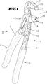
- the pliers legs 2, 3 form grip areas 5, 6 on one side, which, as in the exemplary embodiment, can be covered by grip sleeves.
- the pliers legs 2, 3 form jaws 7, 8, which form a pliers mouth M.
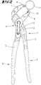
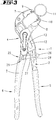
- the jaws 7, 8 are further assigned their free ends to holding elements 9, 10 for holding a spring band clamp 11, see Figures 2 , 3rd .
- the one pliers leg 2 has an adjustment slot 13, which is provided with teeth 12 at least on one of its inner longitudinal sides and extends in the longitudinal direction of the pliers leg 2.
- the other pliers leg 3 is formed in the intersection area 4 with a receptacle 14 for a hinge pin 15.
- the hinge pin 15 is at rest, such as in Fig. 2 is shown in meshing engagement with the toothing 12.
- the mouth width based on a distance of the hinge pin 15 to the upper fixed jaw 7, is fixed. Nevertheless, the jaws can 7 and 8 can still be pivoted relative to one another by pivoting the pliers arm 3 relative to the pliers arm 2.
- Each bracket element 9, 10 is rotatably received in a jaw jaw 7 and 8, respectively.
- a fixed mounting element 9 and / or 10 can also be provided due to the crown-like design of a mounting element 9, 10 provided here.
- FIG. 5 In reference to Fig. 5 the inclusion of a mounting element 9 in a jaw jaw 7 is shown.
- the forceps jaw 7 has a bore 18 which runs transversely to its opening direction and in which a neck section 19 of the holding element 9 is received.
- the neck section 19 has a circumferential groove 20 which is rounded at the bottom.
- a cotter pin 22 is accommodated in a transverse bore 21 to the bore 18, which pin takes out the Holding element 9 prevents, but nevertheless allows rotation of the holding element 9.
- the crown area 23, which is larger in diameter than the neck section 19, is seated on the outside on the associated surface of the jaw 7.
- a mounting element 9, 10 is shown in more detail in Fig. 6 shown.
- both ends E 1 which are wider than the width b of the mounting element, can be securely accommodated in this way, as well as ends E 2 of a spring band clamp, which are narrower than the width b. They then dip into the recess 16 and are thus held in the recess 16.
- depressions 24 are formed on the bottom side in the profile, which preferably run in the form of a circular segment in the said profile.
- the ends E 1 can only be seen on the depressions 24, while the ends E 2 can sit in the middle and deeper into the recess 16.
- a locking device 25 is indicated. Any suitable locking device can be used here. It is shown only by way of example that it can be a locking bolt 26 which has a plurality of latching recesses 27 on one side, which can cooperate with a latching pin 28. While the locking latch 26 rotates, as indicated by a pivot 29 one pliers leg 3 can be attached, the locking pin 28 is attached to the other pliers leg 2.
- the different latching recesses can be used to fix different pivot opening positions of the jaw jaws 7, 8 with respect to one another, with a selected fixed jaw opening width.
- a certain tension state of a spring clip can be maintained.
Landscapes
- Engineering & Computer Science (AREA)
- Mechanical Engineering (AREA)
- Gripping Jigs, Holding Jigs, And Positioning Jigs (AREA)
- Surgical Instruments (AREA)
Description
- Die Erfindung betrifft eine Zange mit Halterungselementen zur Erfassung von Enden einer Federbandschelle.
- Derartige Zangen sind bereits in vielfältiger Hinsicht bekannt geworden. Es wird bspw. auf die
DE 92 16 463 U1 und dieEP 0 677 357 A1 (US 5590573 A ) verwiesen. Bei den bekannten Zangen zur Montage einer Federbandschelle ist mitunter aufgrund einer großen Öffnungsweite des Zangenmauls eine große Öffnung der Zangenschenkel im Griffbereich gegeben. Auch sind im Hinblick auf die gewünschte große Öffnungsweite des Zangenmauls keine günstigen Hebelverhältnisse erreichbar. - Aus der
US 3383963 A ist eine Zange zur Erfassung von Enden von Federbandschellen bekannt, bei der das Zangenmaul ohne eine Feststellbarkeit durch eine Schiebebewegung veränderbar ist. Aus derUS 6128975 A ist eine Zange zur Halterung von Federbandschellen bekannt, bei welcher die in einem festen Gelenk verschwenkbar zueinander angeordneten Zangenschenkel durch eine Schraubverstellung hinsichtlich einer minimalen Öffnungsweite des Zangenmauls einstellbar sind. DieUS 7313984 B1 beschreibt eine nach dem Bowdenzug-Prinzip betätigbare Halterung von Federbandschellen. Aus derUS 2009/ 0064823 A1 ist vergleichbar der US '975 A eine Zange mit in einem feststehenden Gelenk verbundenen Zangenschenkeln bekannt, bei welcher durch eine Rasteinstellung eine Zangenmaulweite feststellbar ist. Aus derDE 4440210 A1 ist eine Zange zur Halterung von Federbandschellen bekannt, bei welcher eine Zangenmaulweite, bei in einem festen Gelenk verbundenen verschwenkbaren Zangenhebeln, einstellbar ist. DieEP 1829647 A2 ,DE 202005013501 U1 undDE 102007049032 A1 offenbaren Zangen, die zur Veränderung der Größe des Zangenmauls in einem Kreuzungsbereich der Zangenschenkel stufenweise zueinander verstellbar sind, wobei zudem ein Zangenschenkel einen Verstellschlitz mit einer Verzahnung aufweist, der sich in Längsrichtung des Zangenschenkels erstreckt und der andere Zangenschenkel mit einem Gelenkbolzen, der den Verstellschlitz durchsetzt, ausgebildet ist, wobei auch der Gelenkbolzen im Ruhezustand in Verzahnungseingriff mit der Verzahnung ist. Die Maulweite, bezogen auf einen Abstand des Gelenkbolzens zu einer oberen feststehenden Maulbacke, ist fixierbar, wobei die Maulbacken jedoch noch relativ zueinander durch Verschwenken der Zangenschenkel verschwenkt werden können. - Aus der
WO99/44790 A1 - Ausgehend von dem dargelegten Stand der Technik beschäftigt sich die Erfindung mit der Aufgabenstellung, eine Zange zur Halterung von Federbandschellen vorteilhaft auszubilden.
- Diese Aufgabe wird durch Anspruch 1 gelöst.
- Es ist bevorzugt, dass ein drehbares Halterungselement mit einer mittigen Vertiefung und umgebend hierzu umfangsmäßig verteilten drei oder mehr Spitzenbereichen ausgebildet ist. Wesentlich ist, dass ein Halterungselement damit sowohl geeignet ist, das eine wie das andere Ende einer Federbandschelle, die unterschiedlich gestaltet sind, halternd aufzunehmen. Während das eine Ende einer Federbandschelle gewöhnlich einen schmaleren, hakenartigen Fortsatz aufweist, weist das andere Ende der Federbandschelle einen die gesamte Breite des
- Federbandes gewöhnlich einnehmenden Flach-Endbereich auf. Dadurch, dass weiter bevorzugt die Halterungselemente auch untereinander gleich ausgebildet sind, bevorzugt gleiche Teile sind, ergibt sich auch diesbezüglich eine Vereinfachung, auch in der Handhabung der Zange. Der Benutzer muss nicht darauf achten, welches Ende der Federbandschelle er beim Aufnehmen der Federbandschelle welcher Maulbacke des Zangenmaules zuordnet.
- Zudem ist bevorzugt, dass ein Halterungselement in seiner Breite an die Breite der Maulbacke angepasst ist. Insbesondere ist bevorzugt, dass ein Halterungselement nicht oder nur unwesentlich in Breitenrichtung über die Maulbacke vorsteht.
- In weiterer Einzelheit ist bevorzugt, dass ein Halterungselement vier Spitzenbereiche aufweist. Darüber hinaus sind die Spitzenbereiche, insbesondere die genannten vier Spitzenbereiche, auch umfangsmäßig mit gleichem Umfangsabstand verteilt vorgesehen.
- Nicht zuletzt ist auch bevorzugt, dass eine Schließstellung des Zangenmauls arretierbar ist. Dies kann bspw. durch an sich bekannte Arretierungsbügel im Bereich der Zangenschenkel erreicht sein.
- Nachstehend ist die Erfindung anhand der beigefügten Zeichnung, die jedoch lediglich ein Ausführungsbeispiel darstellt, erläutert. Hierbei zeigt:
- Fig. 1
- eine perspektivische Ansicht der Zange;
- Fig. 2
- eine Seitenansicht der Zange mit aufgenommenem Federbandring;
- Fig. 3
- eine Darstellung gemäß
Fig. 2 , mit angedeuteter Verriegelungseinrichtung; - Fig. 4
- eine Seitenansicht gemäß
Fig. 2 bzw.Fig. 3 , von der gegenüberliegenden Seite, ohne Federbandschelle; - Fig. 5
- eine Detailansicht, geschnitten, einer Zangenmaulbacke mit darin aufgenommenem Halterungsteil; und
- Fig. 6
- eine Einzeldarstellung eines Halterungselementes.
- Dargestellt und beschrieben ist, zunächst mit Bezug zu
Fig. 1 , eine Zange 1 mit zwei Zangenschenkeln 2, 3, die in einem Kreuzungsbereich 4 gelenkartig miteinander verbunden sind. Auf einer Seite formen die Zangenschenkel 2, 3 Griffbereiche 5, 6 aus, die, wie beim Ausführungsbeispiel, von Griffhüllen überdeckt sein können. Anderseitig des Kreuzungsbereichs 4 formen die Zangenschenkel 2, 3 Maulbacken 7, 8 aus, die ein Zangenmaul M bilden. Die Maulbacken 7, 8 weisen weiter zugeordnet ihren freien Enden Halterungselemente 9, 10 auf, zur Halterung einer Federbandschelle 11, sieheFiguren 2 ,3 . - In weiterer Einzelheit weist der eine Zangenschenkel 2 einen zumindest auf einer seiner inneren Längsseiten mit einer Verzahnung 12 versehenen Verstellschlitz 13 auf, der sich in Längsrichtung des Zangenschenkels 2 erstreckt. Der andere Zangenschenkel 3 ist im Kreuzungsbereich 4 mit einer Aufnahme 14 für einen Gelenkbolzen 15 ausgebildet. Der Gelenkbolzen 15 ist im Ruhezustand, wie etwa in
Fig. 2 dargestellt ist, in Verzahnungseingriff mit der Verzahnung 12. Die Maulweite, bezogen auf einen Abstand des Gelenkbolzens 15 zu der oberen feststehenden Maulbacke 7, ist fixiert. Gleichwohl können die Maulbacken 7 und 8 noch relativ zueinander, durch Verschwenken des Zangenschenkels 3 relativ zu dem Zangenschenkel 2, verschwenkt werden. - Zur Verstellung der Zangenmaulweite ist es gemäß einer Ausführungsform erforderlich, den Gelenkbolzen 15 niederzudrücken. Im niedergedrückten Zustand ist der Verzahnungseingriff aufgehoben und die Zangenschenkel 2, 3 können frei zueinander verstellt werden. Bei einer anderen Ausführungsform ist es jedenfalls möglich, aus einer größeren Stellung zu einer kleineren Stellung die Verstellung der Zangenmaulweite zu erreichen, ohne dass es erforderlich ist, den Gelenkbolzen niederzudrücken. Es ergibt sich ein ratschendes Überlaufen, wie in der
WO 2008/049850 A1 (US 20100064861 A1 ), vgl. insbesondereFiguren 1 bis 6 und zugehörige Beschreibung, in weiterer Einzelheit bspw. erläutert. - Jedes Halterungselement 9, 10 ist frei drehbar in einer Zangenmaulbacke 7 bzw. 8 aufgenommen. Prinzipiell kann aber auch, aufgrund der hier vorgesehenen kronenartigen Ausbildung eines Halterungselements 9, 10, ein feststehendes Halterungselement 9 und/oder 10 vorgesehen sein.
- Mit Bezug zu
Fig. 5 ist die Aufnahme eines Halterungselementes 9 in einer Zangenmaulbacke 7 dargestellt. - Die Zangenmaulbacke 7 weist eine quer zu ihrer Öffnungsrichtung verlaufende Bohrung 18 auf, in welcher ein Halsabschnitt 19 des Halterungselementes 9 aufgenommen ist. Der Halsabschnitt 19 weist in weiterer Einzelheit eine umlaufende, bodenseitig gerundete Nut 20 auf. In einer Querbohrung 21 zu der Bohrung 18 ist beim Ausführungsbeispiel zur drehbaren Halterung des Halterungselementes 9 ein Splintstift 22 aufgenommen, der ein Herausnehmen des Halterungselementes 9 hindert, gleichwohl aber eine Drehung des Halterungselementes 9 ermöglicht.
- Der gegenüber dem Halsabschnitt 19 durchmessergrößere Kronenbereich 23 sitzt außen auf der zugeordneten Fläche der Maulbacke 7 auf.
- Ein Halterungselement 9, 10 ist in weiterer Einzelheit in
Fig. 6 dargestellt. - Wesentlich ist, dass eine mittige Vertiefung 16 des Halterungselements 9, 10 beim Ausführungsbeispiel von vier Spitzenbereichen 17 umgeben ist. Wie strichpunktiert angedeutet ist, können auf diese Art sowohl Enden E1, die breiter sind, als es der Breite b des Halterungselements entspricht, hierin sicher aufgenommen werden, wie auch Enden E2 einer Federbandschelle, die schmaler sind als es der Breite b entspricht. Sie tauchen dann in die Vertiefung 16 ein und sind so in der Vertiefung 16 gehaltert.
- Zwischen den Spitzenbereichen 17 sind bodenseitig im Profil gerundete Einsenkungen 24 ausgebildet, die vorzugsweise in dem genannten Profil kreisabschnittförmig verlaufen. Die Enden E1 sitzen ersichtlich nur auf den Einsenkungen 24, während die Enden E2 mittig und tiefer in die Vertiefung 16 eingreifend einsitzen können.
- Mit Bezug zu
Fig. 3 ist eine Verriegelungseinrichtung 25 angedeutet. Es kann hier jede geeignete Verriegelungseinrichtung zur Anwendung kommen. Lediglich beispielhaft ist dargestellt, dass es sich um einen Verriegelungsriegel 26 handeln kann, der auf einer Seite eine Mehrzahl von Rastausnehmungen 27 aufweist, die mit einem Rastzapfen 28 zusammenwirken können. Während der Verriegelungsriegel 26 drehbar, wie durch ein Drehgelenk 29 angedeutet, an dem einen Zangenschenkel 3 befestigt sein kann, ist der Rastzapfen 28 an dem anderen Zangenschenkel 2 befestigt. Die unterschiedlichen Rastausnehmungen können zur Festsetzung unterschiedlicher Schwenköffnungsstellungen der Zangenmaulbacken 7, 8 zueinander, bei einer gewählten fixierten Zangenmaulöffnungsweite, genutzt werden. - Ein bestimmter Spannungszustand einer gefassten Federbandschelle kann so aufrechterhalten werden.
-
- 1
- Zange
- 2
- Zangenschenkel
- 3
- Zangenschenkel
- 4
- Kreuzungsbereich
- 5
- Griffbereich
- 6
- Griffbereich
- 7
- Maulbacke
- 8
- Maulbacke
- 9
- Halterungselement
- 10
- Halterungselement
- 11
- Federbandschelle
- 12
- Verzahnung
- 13
- Verstellschlitz
- 14
- Aufnahme
- 15
- Gelenkbolzen
- 16
- Vertiefung
- 17
- Spitzenbereiche
- 18
- Bohrung
- 19
- Halsabschnitt
- 20
- Nut
- 21
- Querbohrung
- 22
- Splintstift
- 23
- Kronenbereich
- 24
- Einsenkung
- 25
- Verriegelungseinrichtung
- 26
- Verriegelungsriegel
- 27
- Rastausnehmung
- 28
- Rastzapfen
- 29
- Drehgelenk
- E1
- Ende
- E2
- Ende
- M
- Zangenmaul
- b
- Breite
Claims (5)
- Zange (1) mit zwei Zangenschenkeln (2, 3) und einem durch Maulbacken (7, 8) gebildeten Zangenmaul (M), wobei in dem Zangenmaul (M) relativ zu einer Maulbacke (7, 8) kronenartige drehbare oder feststehende Halterungselemente (9) zur Erfassung von Enden einer Federbandschelle (11) angeordnet sind, wobei die feststehenden Halterungselemente (9, 10) mit einer mittigen Vertiefung (16) und umgebend hierzu umfangmäßig verteilten drei oder mehr Spitzenbereichen (17) vorgesehen sind, und die Zangenschenkel (2, 3) in einem Kreuzungsbereich (4) miteinander verbunden sind, wobei die Zangenschenkel (2, 3) zur Veränderung der Größe des Zangenmauls (M) in dem Kreuzungsbereich (4) stufenweise zueinander verstellbar sind, der eine Zangenschenkel (2) einen zumindest auf einer seiner inneren Längsseiten mit einer Verzahnung (12) versehenen Verstellschlitz (13) aufweist, der sich in Längsrichtung des Zangenschenkels (2) erstreckt, der andere Zangenschenkel (3) in dem Kreuzungsbereich (4) mit einer Aufnahme (14) für einen Gelenkbolzen (15) ausgebildet ist und der Gelenkbolzen (15) im Ruhezustand in Verzahnungseingriff mit der Verzahnung (12) ist, wobei die Maulweite, bezogen auf einen Abstand des Gelenkbolzens (15) zu der oberen feststehenden Maulbacke (7), fixiert ist, die Maulbacken (7 und 8) jedoch noch relativ zueinander, durch Verschwenken des Zangenschenkels (3) relativ zu dem Zangenschenkel (2), verschwenkt werden können..
- Zange nach Anspruch 1, dadurch gekennzeichnet, dass ein drehbares Halterungselement (9, 10) mit einer mittigen Vertiefung (16) und umgebend hierzu umfangsmäßig verteilten drei oder mehr Spitzenbereichen (17) ausgebildet ist.
- Zange nach einem der vorhergehenden Ansprüche, dadurch gekennzeichnet, dass die Halterungselemente (9, 10) untereinander gleich ausgebildet sind.
- Zange nach einem der vorhergehenden Ansprüche 2 oder 3, dadurch gekennzeichnet, dass vier Spitzenbereiche (17) ausgebildet sind.
- Zange nach einem der vorhergehenden Ansprüche, dadurch gekennzeichnet, dass eine Schließstellung des Zangenmauls (M) arretierbar ist.
Applications Claiming Priority (2)
| Application Number | Priority Date | Filing Date | Title |
|---|---|---|---|
| DE102011054986A DE102011054986A1 (de) | 2011-11-02 | 2011-11-02 | Zange |
| PCT/EP2012/071038 WO2013064402A1 (de) | 2011-11-02 | 2012-10-24 | Zange |
Publications (2)
| Publication Number | Publication Date |
|---|---|
| EP2773490A1 EP2773490A1 (de) | 2014-09-10 |
| EP2773490B1 true EP2773490B1 (de) | 2020-07-01 |
Family
ID=47088863
Family Applications (1)
| Application Number | Title | Priority Date | Filing Date |
|---|---|---|---|
| EP12779037.6A Active EP2773490B1 (de) | 2011-11-02 | 2012-10-24 | Zange |
Country Status (5)
| Country | Link |
|---|---|
| US (1) | US20140290447A1 (de) |
| EP (1) | EP2773490B1 (de) |
| CN (1) | CN104023917B (de) |
| DE (1) | DE102011054986A1 (de) |
| WO (1) | WO2013064402A1 (de) |
Families Citing this family (14)
| Publication number | Priority date | Publication date | Assignee | Title |
|---|---|---|---|---|
| DE102013105240A1 (de) * | 2013-05-22 | 2014-11-27 | Aesculap Ag | Stabhaltezange mit Winkelverstellung |
| DE102013111211B4 (de) | 2013-10-10 | 2022-12-22 | Knipex-Werk C. Gustav Putsch Kg | Zange |
| DE102015102046A1 (de) | 2015-02-12 | 2016-08-18 | Knipex-Werk C. Gustav Putsch Kg | Zange |
| TWI569929B (zh) * | 2015-06-02 | 2017-02-11 | 傑望有限公司 | 束件拆裝工具 |
| CN107900949B (zh) * | 2017-11-27 | 2024-04-12 | 邵东县中南锻压工具制造有限公司 | 一种半自动多功能速拧扳手 |
| US20190160637A1 (en) * | 2017-11-29 | 2019-05-30 | Jaw Ling Co., Ltd. | Hose clamp tool gun |
| US10661414B2 (en) | 2018-02-21 | 2020-05-26 | Snap-On Incorporated | Tool with handle offsets |
| CN109441921B (zh) * | 2018-11-05 | 2021-05-28 | 南通大学 | 一种反射镜片与底座的安装保护装置及其夹持装置 |
| US11819987B2 (en) * | 2020-04-06 | 2023-11-21 | Apex Brands, Inc. | Dual-mode adjustable pliers |
| CN117157172A (zh) * | 2021-04-07 | 2023-12-01 | 科尼佩克斯-沃克·C·古斯塔夫普奇公司 | 钳子 |
| GB2617198A (en) * | 2022-04-01 | 2023-10-04 | Reliance Worldwide Corporation Uk Ltd | A tool for a plumbing connector |
| US12390913B2 (en) * | 2023-04-12 | 2025-08-19 | A & E Incorporated | Hose clamp pliers |
| US12605812B2 (en) * | 2023-04-12 | 2026-04-21 | A&E Incorporated | Hose clamp pliers |
| US12420391B2 (en) * | 2023-06-30 | 2025-09-23 | Snap-On Incorporated | Hose clamp pliers |
Citations (4)
| Publication number | Priority date | Publication date | Assignee | Title |
|---|---|---|---|---|
| WO1999044790A1 (en) * | 1998-03-02 | 1999-09-10 | Emerson Electric Co. | Laminated self-adjusting pliers |
| DE202005013501U1 (de) * | 2005-08-26 | 2005-11-03 | NWS Germany Produktion W. Nöthen e.K. | Automatische Montagezange |
| EP1829647A2 (de) * | 2006-03-02 | 2007-09-05 | Eduard Wille GmbH & Co KG | Zange mit geschützter Zwangsführung |
| DE102007049032A1 (de) * | 2006-10-24 | 2008-04-30 | Knipex-Werk C. Gustav Putsch Kg | Zange |
Family Cites Families (19)
| Publication number | Priority date | Publication date | Assignee | Title |
|---|---|---|---|---|
| US172982A (en) * | 1876-02-01 | Improvement in clamps for hose-couplings | ||
| US2541424A (en) * | 1949-03-04 | 1951-02-13 | Leo J Koch | Link friction pin pliers |
| US3013456A (en) * | 1959-09-29 | 1961-12-19 | Ericson Alf Ernferd | Plier with locking feature on pawl |
| US3383963A (en) * | 1967-03-03 | 1968-05-21 | Wallace R. Vondrachek | Pivoted gripping tool having removable swivelly mounted jaws |
| US3672245A (en) * | 1971-03-15 | 1972-06-27 | Charles F Hoffman | Wrench |
| DE9113870U1 (de) | 1991-08-08 | 1992-12-10 | Knipex-Werk C. Gustav Putsch, 5600 Wuppertal | Zange mit zwei Zangenschenkeln |
| US5113727A (en) * | 1991-10-28 | 1992-05-19 | Stanley-Bostitch, Inc. | Pliers with removable jaw inserts |
| DE9216463U1 (de) | 1992-12-03 | 1993-01-14 | Hazet-Werk Hermann Zerver Gmbh & Co Kg, 5630 Remscheid | Federbandschellenzange |
| FR2718381B1 (fr) | 1994-04-12 | 1996-06-28 | Caillau Ets | Paire de mâchoires destinées à être montées sur les bras d'une pince pour serrer un collier. |
| US5507206A (en) * | 1994-06-06 | 1996-04-16 | Ford Motor Company | Hose clamp tool |
| DE4440210A1 (de) * | 1994-11-10 | 1996-05-15 | Saltus Werk Max Forst Gmbh | Schlauchschellen-Zange |
| US5566438A (en) * | 1995-01-17 | 1996-10-22 | Bullock; Rothel J. | Tool for reconnecting a fuel hose safety break away |
| US6128975A (en) * | 1996-03-01 | 2000-10-10 | Schley; Paul E. | Hose clamp pliers & method |
| US6116124A (en) * | 1997-08-12 | 2000-09-12 | Great Neck Saw Manufacturers, Inc. | Adjustable pliers |
| DE10259575B4 (de) * | 2002-12-19 | 2007-05-31 | Daimlerchrysler Ag | Schellenmontagezange |
| US7313984B1 (en) * | 2005-07-27 | 2008-01-01 | Snap-On Incorporated | Universal retention cavities for cable-mounted remote hose clamp pliers heads |
| CN201015848Y (zh) * | 2007-03-08 | 2008-02-06 | 上海昆杰五金工具有限公司 | 可自锁和自动解锁的大力钳 |
| US20090064823A1 (en) * | 2007-09-11 | 2009-03-12 | Chuan Mao Huang | Hose clamp pliers |
| US20100058895A1 (en) * | 2008-09-10 | 2010-03-11 | Ming-Chieh Wu | Hose Clamp Pliers |
-
2011
- 2011-11-02 DE DE102011054986A patent/DE102011054986A1/de not_active Withdrawn
-
2012
- 2012-10-24 EP EP12779037.6A patent/EP2773490B1/de active Active
- 2012-10-24 CN CN201280053501.5A patent/CN104023917B/zh active Active
- 2012-10-24 US US14/355,670 patent/US20140290447A1/en not_active Abandoned
- 2012-10-24 WO PCT/EP2012/071038 patent/WO2013064402A1/de not_active Ceased
Patent Citations (4)
| Publication number | Priority date | Publication date | Assignee | Title |
|---|---|---|---|---|
| WO1999044790A1 (en) * | 1998-03-02 | 1999-09-10 | Emerson Electric Co. | Laminated self-adjusting pliers |
| DE202005013501U1 (de) * | 2005-08-26 | 2005-11-03 | NWS Germany Produktion W. Nöthen e.K. | Automatische Montagezange |
| EP1829647A2 (de) * | 2006-03-02 | 2007-09-05 | Eduard Wille GmbH & Co KG | Zange mit geschützter Zwangsführung |
| DE102007049032A1 (de) * | 2006-10-24 | 2008-04-30 | Knipex-Werk C. Gustav Putsch Kg | Zange |
Also Published As
| Publication number | Publication date |
|---|---|
| WO2013064402A1 (de) | 2013-05-10 |
| DE102011054986A1 (de) | 2013-05-02 |
| US20140290447A1 (en) | 2014-10-02 |
| CN104023917A (zh) | 2014-09-03 |
| EP2773490A1 (de) | 2014-09-10 |
| CN104023917B (zh) | 2016-07-27 |
Similar Documents
| Publication | Publication Date | Title |
|---|---|---|
| DE102007049032B4 (de) | Zange | |
| DE102011054986A1 (de) | Zange | |
| EP3113908B1 (de) | Zange | |
| DE102009050865B3 (de) | Montagezange mit lösbarer Gegenklinke | |
| DE202014101515U1 (de) | Klappfahrradspezifische zweifache Schnelllöseeinheit | |
| EP3784439B1 (de) | Zange | |
| EP4103357B1 (de) | Zange | |
| EP3863789A1 (de) | Rohrschneidegerät | |
| EP2636489B1 (de) | Wasserpumpenzange mit Betätigungshebel | |
| EP1724893A1 (de) | Werkzeug zum Abmanteln eines Kabels | |
| DE20120275U1 (de) | Kabelschneider | |
| EP2576152B1 (de) | Gerätehalter | |
| DE102016125517B4 (de) | Handwerkzeug mit einer Ratschenfunktion | |
| DE19909224B4 (de) | Montagezange mit verstellbarer Maulweite | |
| EP1944135B1 (de) | Spannwerkzeug mit einem Standfuß | |
| DE202014102320U1 (de) | Fahrradrahmenadapter | |
| EP3563973B1 (de) | Zange | |
| WO2024223573A1 (de) | Abisolierzange mit zwei zangenbacken | |
| EP1336446B1 (de) | Verstellbarer Tiefenanschlag für ein handgetragenes Arbeitsgerät | |
| EP2578891B1 (de) | Adapter | |
| EP1584265A2 (de) | Rastbeschlag | |
| DE102013217874B3 (de) | Zange | |
| DE10044874A1 (de) | Schlüsselzange | |
| DE102006031721B4 (de) | Schraubzange | |
| DE202008001949U1 (de) | Greifzange |
Legal Events
| Date | Code | Title | Description |
|---|---|---|---|
| PUAI | Public reference made under article 153(3) epc to a published international application that has entered the european phase |
Free format text: ORIGINAL CODE: 0009012 |
|
| 17P | Request for examination filed |
Effective date: 20140522 |
|
| AK | Designated contracting states |
Kind code of ref document: A1 Designated state(s): AL AT BE BG CH CY CZ DE DK EE ES FI FR GB GR HR HU IE IS IT LI LT LU LV MC MK MT NL NO PL PT RO RS SE SI SK SM TR |
|
| DAX | Request for extension of the european patent (deleted) | ||
| 17Q | First examination report despatched |
Effective date: 20151216 |
|
| STAA | Information on the status of an ep patent application or granted ep patent |
Free format text: STATUS: EXAMINATION IS IN PROGRESS |
|
| GRAP | Despatch of communication of intention to grant a patent |
Free format text: ORIGINAL CODE: EPIDOSNIGR1 |
|
| STAA | Information on the status of an ep patent application or granted ep patent |
Free format text: STATUS: GRANT OF PATENT IS INTENDED |
|
| INTG | Intention to grant announced |
Effective date: 20200113 |
|
| GRAS | Grant fee paid |
Free format text: ORIGINAL CODE: EPIDOSNIGR3 |
|
| GRAA | (expected) grant |
Free format text: ORIGINAL CODE: 0009210 |
|
| STAA | Information on the status of an ep patent application or granted ep patent |
Free format text: STATUS: THE PATENT HAS BEEN GRANTED |
|
| AK | Designated contracting states |
Kind code of ref document: B1 Designated state(s): AL AT BE BG CH CY CZ DE DK EE ES FI FR GB GR HR HU IE IS IT LI LT LU LV MC MK MT NL NO PL PT RO RS SE SI SK SM TR |
|
| REG | Reference to a national code |
Ref country code: GB Ref legal event code: FG4D Free format text: NOT ENGLISH |
|
| REG | Reference to a national code |
Ref country code: CH Ref legal event code: EP Ref country code: AT Ref legal event code: REF Ref document number: 1285720 Country of ref document: AT Kind code of ref document: T Effective date: 20200715 |
|
| REG | Reference to a national code |
Ref country code: IE Ref legal event code: FG4D Free format text: LANGUAGE OF EP DOCUMENT: GERMAN |
|
| REG | Reference to a national code |
Ref country code: DE Ref legal event code: R096 Ref document number: 502012016192 Country of ref document: DE |
|
| REG | Reference to a national code |
Ref country code: LT Ref legal event code: MG4D |
|
| PG25 | Lapsed in a contracting state [announced via postgrant information from national office to epo] |
Ref country code: BG Free format text: LAPSE BECAUSE OF FAILURE TO SUBMIT A TRANSLATION OF THE DESCRIPTION OR TO PAY THE FEE WITHIN THE PRESCRIBED TIME-LIMIT Effective date: 20201001 |
|
| REG | Reference to a national code |
Ref country code: NL Ref legal event code: MP Effective date: 20200701 |
|
| PG25 | Lapsed in a contracting state [announced via postgrant information from national office to epo] |
Ref country code: LT Free format text: LAPSE BECAUSE OF FAILURE TO SUBMIT A TRANSLATION OF THE DESCRIPTION OR TO PAY THE FEE WITHIN THE PRESCRIBED TIME-LIMIT Effective date: 20200701 Ref country code: FI Free format text: LAPSE BECAUSE OF FAILURE TO SUBMIT A TRANSLATION OF THE DESCRIPTION OR TO PAY THE FEE WITHIN THE PRESCRIBED TIME-LIMIT Effective date: 20200701 Ref country code: PT Free format text: LAPSE BECAUSE OF FAILURE TO SUBMIT A TRANSLATION OF THE DESCRIPTION OR TO PAY THE FEE WITHIN THE PRESCRIBED TIME-LIMIT Effective date: 20201102 Ref country code: SE Free format text: LAPSE BECAUSE OF FAILURE TO SUBMIT A TRANSLATION OF THE DESCRIPTION OR TO PAY THE FEE WITHIN THE PRESCRIBED TIME-LIMIT Effective date: 20200701 Ref country code: ES Free format text: LAPSE BECAUSE OF FAILURE TO SUBMIT A TRANSLATION OF THE DESCRIPTION OR TO PAY THE FEE WITHIN THE PRESCRIBED TIME-LIMIT Effective date: 20200701 Ref country code: HR Free format text: LAPSE BECAUSE OF FAILURE TO SUBMIT A TRANSLATION OF THE DESCRIPTION OR TO PAY THE FEE WITHIN THE PRESCRIBED TIME-LIMIT Effective date: 20200701 Ref country code: CZ Free format text: LAPSE BECAUSE OF FAILURE TO SUBMIT A TRANSLATION OF THE DESCRIPTION OR TO PAY THE FEE WITHIN THE PRESCRIBED TIME-LIMIT Effective date: 20200701 Ref country code: GR Free format text: LAPSE BECAUSE OF FAILURE TO SUBMIT A TRANSLATION OF THE DESCRIPTION OR TO PAY THE FEE WITHIN THE PRESCRIBED TIME-LIMIT Effective date: 20201002 Ref country code: NO Free format text: LAPSE BECAUSE OF FAILURE TO SUBMIT A TRANSLATION OF THE DESCRIPTION OR TO PAY THE FEE WITHIN THE PRESCRIBED TIME-LIMIT Effective date: 20201001 |
|
| PG25 | Lapsed in a contracting state [announced via postgrant information from national office to epo] |
Ref country code: RS Free format text: LAPSE BECAUSE OF FAILURE TO SUBMIT A TRANSLATION OF THE DESCRIPTION OR TO PAY THE FEE WITHIN THE PRESCRIBED TIME-LIMIT Effective date: 20200701 Ref country code: PL Free format text: LAPSE BECAUSE OF FAILURE TO SUBMIT A TRANSLATION OF THE DESCRIPTION OR TO PAY THE FEE WITHIN THE PRESCRIBED TIME-LIMIT Effective date: 20200701 Ref country code: LV Free format text: LAPSE BECAUSE OF FAILURE TO SUBMIT A TRANSLATION OF THE DESCRIPTION OR TO PAY THE FEE WITHIN THE PRESCRIBED TIME-LIMIT Effective date: 20200701 Ref country code: IS Free format text: LAPSE BECAUSE OF FAILURE TO SUBMIT A TRANSLATION OF THE DESCRIPTION OR TO PAY THE FEE WITHIN THE PRESCRIBED TIME-LIMIT Effective date: 20201101 |
|
| PG25 | Lapsed in a contracting state [announced via postgrant information from national office to epo] |
Ref country code: NL Free format text: LAPSE BECAUSE OF FAILURE TO SUBMIT A TRANSLATION OF THE DESCRIPTION OR TO PAY THE FEE WITHIN THE PRESCRIBED TIME-LIMIT Effective date: 20200701 |
|
| REG | Reference to a national code |
Ref country code: DE Ref legal event code: R097 Ref document number: 502012016192 Country of ref document: DE |
|
| PG25 | Lapsed in a contracting state [announced via postgrant information from national office to epo] |
Ref country code: DK Free format text: LAPSE BECAUSE OF FAILURE TO SUBMIT A TRANSLATION OF THE DESCRIPTION OR TO PAY THE FEE WITHIN THE PRESCRIBED TIME-LIMIT Effective date: 20200701 Ref country code: EE Free format text: LAPSE BECAUSE OF FAILURE TO SUBMIT A TRANSLATION OF THE DESCRIPTION OR TO PAY THE FEE WITHIN THE PRESCRIBED TIME-LIMIT Effective date: 20200701 Ref country code: IT Free format text: LAPSE BECAUSE OF FAILURE TO SUBMIT A TRANSLATION OF THE DESCRIPTION OR TO PAY THE FEE WITHIN THE PRESCRIBED TIME-LIMIT Effective date: 20200701 Ref country code: RO Free format text: LAPSE BECAUSE OF FAILURE TO SUBMIT A TRANSLATION OF THE DESCRIPTION OR TO PAY THE FEE WITHIN THE PRESCRIBED TIME-LIMIT Effective date: 20200701 Ref country code: SM Free format text: LAPSE BECAUSE OF FAILURE TO SUBMIT A TRANSLATION OF THE DESCRIPTION OR TO PAY THE FEE WITHIN THE PRESCRIBED TIME-LIMIT Effective date: 20200701 |
|
| PLBE | No opposition filed within time limit |
Free format text: ORIGINAL CODE: 0009261 |
|
| STAA | Information on the status of an ep patent application or granted ep patent |
Free format text: STATUS: NO OPPOSITION FILED WITHIN TIME LIMIT |
|
| PG25 | Lapsed in a contracting state [announced via postgrant information from national office to epo] |
Ref country code: AL Free format text: LAPSE BECAUSE OF FAILURE TO SUBMIT A TRANSLATION OF THE DESCRIPTION OR TO PAY THE FEE WITHIN THE PRESCRIBED TIME-LIMIT Effective date: 20200701 |
|
| REG | Reference to a national code |
Ref country code: CH Ref legal event code: PL |
|
| 26N | No opposition filed |
Effective date: 20210406 |
|
| GBPC | Gb: european patent ceased through non-payment of renewal fee |
Effective date: 20201024 |
|
| PG25 | Lapsed in a contracting state [announced via postgrant information from national office to epo] |
Ref country code: LU Free format text: LAPSE BECAUSE OF NON-PAYMENT OF DUE FEES Effective date: 20201024 Ref country code: MC Free format text: LAPSE BECAUSE OF FAILURE TO SUBMIT A TRANSLATION OF THE DESCRIPTION OR TO PAY THE FEE WITHIN THE PRESCRIBED TIME-LIMIT Effective date: 20200701 Ref country code: SK Free format text: LAPSE BECAUSE OF FAILURE TO SUBMIT A TRANSLATION OF THE DESCRIPTION OR TO PAY THE FEE WITHIN THE PRESCRIBED TIME-LIMIT Effective date: 20200701 |
|
| REG | Reference to a national code |
Ref country code: BE Ref legal event code: MM Effective date: 20201031 |
|
| PG25 | Lapsed in a contracting state [announced via postgrant information from national office to epo] |
Ref country code: FR Free format text: LAPSE BECAUSE OF NON-PAYMENT OF DUE FEES Effective date: 20201031 |
|
| PG25 | Lapsed in a contracting state [announced via postgrant information from national office to epo] |
Ref country code: BE Free format text: LAPSE BECAUSE OF NON-PAYMENT OF DUE FEES Effective date: 20201031 Ref country code: CH Free format text: LAPSE BECAUSE OF NON-PAYMENT OF DUE FEES Effective date: 20201031 Ref country code: SI Free format text: LAPSE BECAUSE OF FAILURE TO SUBMIT A TRANSLATION OF THE DESCRIPTION OR TO PAY THE FEE WITHIN THE PRESCRIBED TIME-LIMIT Effective date: 20200701 Ref country code: LI Free format text: LAPSE BECAUSE OF NON-PAYMENT OF DUE FEES Effective date: 20201031 Ref country code: GB Free format text: LAPSE BECAUSE OF NON-PAYMENT OF DUE FEES Effective date: 20201024 |
|
| PG25 | Lapsed in a contracting state [announced via postgrant information from national office to epo] |
Ref country code: IE Free format text: LAPSE BECAUSE OF NON-PAYMENT OF DUE FEES Effective date: 20201024 |
|
| REG | Reference to a national code |
Ref country code: AT Ref legal event code: MM01 Ref document number: 1285720 Country of ref document: AT Kind code of ref document: T Effective date: 20201024 |
|
| PG25 | Lapsed in a contracting state [announced via postgrant information from national office to epo] |
Ref country code: AT Free format text: LAPSE BECAUSE OF NON-PAYMENT OF DUE FEES Effective date: 20201024 |
|
| PG25 | Lapsed in a contracting state [announced via postgrant information from national office to epo] |
Ref country code: TR Free format text: LAPSE BECAUSE OF FAILURE TO SUBMIT A TRANSLATION OF THE DESCRIPTION OR TO PAY THE FEE WITHIN THE PRESCRIBED TIME-LIMIT Effective date: 20200701 Ref country code: MT Free format text: LAPSE BECAUSE OF FAILURE TO SUBMIT A TRANSLATION OF THE DESCRIPTION OR TO PAY THE FEE WITHIN THE PRESCRIBED TIME-LIMIT Effective date: 20200701 Ref country code: CY Free format text: LAPSE BECAUSE OF FAILURE TO SUBMIT A TRANSLATION OF THE DESCRIPTION OR TO PAY THE FEE WITHIN THE PRESCRIBED TIME-LIMIT Effective date: 20200701 |
|
| PG25 | Lapsed in a contracting state [announced via postgrant information from national office to epo] |
Ref country code: MK Free format text: LAPSE BECAUSE OF FAILURE TO SUBMIT A TRANSLATION OF THE DESCRIPTION OR TO PAY THE FEE WITHIN THE PRESCRIBED TIME-LIMIT Effective date: 20200701 |
|
| P01 | Opt-out of the competence of the unified patent court (upc) registered |
Effective date: 20230528 |
|
| PGFP | Annual fee paid to national office [announced via postgrant information from national office to epo] |
Ref country code: DE Payment date: 20251020 Year of fee payment: 14 |