EP2771142B1 - Werkzeugsystem - Google Patents
Werkzeugsystem Download PDFInfo
- Publication number
- EP2771142B1 EP2771142B1 EP12778112.8A EP12778112A EP2771142B1 EP 2771142 B1 EP2771142 B1 EP 2771142B1 EP 12778112 A EP12778112 A EP 12778112A EP 2771142 B1 EP2771142 B1 EP 2771142B1
- Authority
- EP
- European Patent Office
- Prior art keywords
- clamping
- tool
- adapter
- clamping element
- cutting plate
- Prior art date
- Legal status (The legal status is an assumption and is not a legal conclusion. Google has not performed a legal analysis and makes no representation as to the accuracy of the status listed.)
- Active
Links
- 238000005520 cutting process Methods 0.000 claims description 73
- 239000002826 coolant Substances 0.000 claims description 16
- 239000000463 material Substances 0.000 claims description 6
- 238000003754 machining Methods 0.000 claims description 4
- 230000007704 transition Effects 0.000 claims description 4
- 230000001419 dependent effect Effects 0.000 claims 1
- 229910000831 Steel Inorganic materials 0.000 description 7
- 239000010959 steel Substances 0.000 description 7
- 238000000034 method Methods 0.000 description 3
- 241001136792 Alle Species 0.000 description 2
- 239000000919 ceramic Substances 0.000 description 2
- 238000003825 pressing Methods 0.000 description 2
- 230000000717 retained effect Effects 0.000 description 2
- 241000473267 Uca major Species 0.000 description 1
- 239000002131 composite material Substances 0.000 description 1
- 239000002184 metal Substances 0.000 description 1
Images


Classifications
-
- B—PERFORMING OPERATIONS; TRANSPORTING
- B23—MACHINE TOOLS; METAL-WORKING NOT OTHERWISE PROVIDED FOR
- B23B—TURNING; BORING
- B23B27/00—Tools for turning or boring machines; Tools of a similar kind in general; Accessories therefor
- B23B27/14—Cutting tools of which the bits or tips or cutting inserts are of special material
- B23B27/16—Cutting tools of which the bits or tips or cutting inserts are of special material with exchangeable cutting bits or cutting inserts, e.g. able to be clamped
- B23B27/1625—Cutting tools of which the bits or tips or cutting inserts are of special material with exchangeable cutting bits or cutting inserts, e.g. able to be clamped with plate-like cutting inserts of special shape clamped by a clamping member acting almost perpendicularly on the chip-forming plane
-
- B—PERFORMING OPERATIONS; TRANSPORTING
- B23—MACHINE TOOLS; METAL-WORKING NOT OTHERWISE PROVIDED FOR
- B23B—TURNING; BORING
- B23B27/00—Tools for turning or boring machines; Tools of a similar kind in general; Accessories therefor
- B23B27/14—Cutting tools of which the bits or tips or cutting inserts are of special material
- B23B27/16—Cutting tools of which the bits or tips or cutting inserts are of special material with exchangeable cutting bits or cutting inserts, e.g. able to be clamped
- B23B27/1666—Cutting tools of which the bits or tips or cutting inserts are of special material with exchangeable cutting bits or cutting inserts, e.g. able to be clamped with plate-like cutting inserts clamped by a clamping member acting almost perpendicularly on chip-forming plane
-
- B—PERFORMING OPERATIONS; TRANSPORTING
- B23—MACHINE TOOLS; METAL-WORKING NOT OTHERWISE PROVIDED FOR
- B23B—TURNING; BORING
- B23B27/00—Tools for turning or boring machines; Tools of a similar kind in general; Accessories therefor
- B23B27/10—Cutting tools with special provision for cooling
-
- B—PERFORMING OPERATIONS; TRANSPORTING
- B23—MACHINE TOOLS; METAL-WORKING NOT OTHERWISE PROVIDED FOR
- B23B—TURNING; BORING
- B23B27/00—Tools for turning or boring machines; Tools of a similar kind in general; Accessories therefor
- B23B27/14—Cutting tools of which the bits or tips or cutting inserts are of special material
- B23B27/16—Cutting tools of which the bits or tips or cutting inserts are of special material with exchangeable cutting bits or cutting inserts, e.g. able to be clamped
-
- B—PERFORMING OPERATIONS; TRANSPORTING
- B23—MACHINE TOOLS; METAL-WORKING NOT OTHERWISE PROVIDED FOR
- B23B—TURNING; BORING
- B23B2200/00—Details of cutting inserts
- B23B2200/08—Rake or top surfaces
- B23B2200/086—Rake or top surfaces with one or more grooves
- B23B2200/088—Rake or top surfaces with one or more grooves for clamping
-
- B—PERFORMING OPERATIONS; TRANSPORTING
- B23—MACHINE TOOLS; METAL-WORKING NOT OTHERWISE PROVIDED FOR
- B23B—TURNING; BORING
- B23B2231/00—Details of chucks, toolholder shanks or tool shanks
- B23B2231/04—Adapters
-
- B—PERFORMING OPERATIONS; TRANSPORTING
- B23—MACHINE TOOLS; METAL-WORKING NOT OTHERWISE PROVIDED FOR
- B23B—TURNING; BORING
- B23B2250/00—Compensating adverse effects during turning, boring or drilling
- B23B2250/12—Cooling and lubrication
-
- Y—GENERAL TAGGING OF NEW TECHNOLOGICAL DEVELOPMENTS; GENERAL TAGGING OF CROSS-SECTIONAL TECHNOLOGIES SPANNING OVER SEVERAL SECTIONS OF THE IPC; TECHNICAL SUBJECTS COVERED BY FORMER USPC CROSS-REFERENCE ART COLLECTIONS [XRACs] AND DIGESTS
- Y10—TECHNICAL SUBJECTS COVERED BY FORMER USPC
- Y10T—TECHNICAL SUBJECTS COVERED BY FORMER US CLASSIFICATION
- Y10T407/00—Cutters, for shaping
- Y10T407/14—Cutters, for shaping with means to apply fluid to cutting tool
-
- Y—GENERAL TAGGING OF NEW TECHNOLOGICAL DEVELOPMENTS; GENERAL TAGGING OF CROSS-SECTIONAL TECHNOLOGIES SPANNING OVER SEVERAL SECTIONS OF THE IPC; TECHNICAL SUBJECTS COVERED BY FORMER USPC CROSS-REFERENCE ART COLLECTIONS [XRACs] AND DIGESTS
- Y10—TECHNICAL SUBJECTS COVERED BY FORMER USPC
- Y10T—TECHNICAL SUBJECTS COVERED BY FORMER US CLASSIFICATION
- Y10T407/00—Cutters, for shaping
- Y10T407/22—Cutters, for shaping including holder having seat for inserted tool
- Y10T407/227—Cutters, for shaping including holder having seat for inserted tool with separate means to fasten tool seat to holder
-
- Y—GENERAL TAGGING OF NEW TECHNOLOGICAL DEVELOPMENTS; GENERAL TAGGING OF CROSS-SECTIONAL TECHNOLOGIES SPANNING OVER SEVERAL SECTIONS OF THE IPC; TECHNICAL SUBJECTS COVERED BY FORMER USPC CROSS-REFERENCE ART COLLECTIONS [XRACs] AND DIGESTS
- Y10—TECHNICAL SUBJECTS COVERED BY FORMER USPC
- Y10T—TECHNICAL SUBJECTS COVERED BY FORMER US CLASSIFICATION
- Y10T407/00—Cutters, for shaping
- Y10T407/22—Cutters, for shaping including holder having seat for inserted tool
- Y10T407/2272—Cutters, for shaping including holder having seat for inserted tool with separate means to fasten tool to holder
- Y10T407/2282—Cutters, for shaping including holder having seat for inserted tool with separate means to fasten tool to holder including tool holding clamp and clamp actuator
-
- Y—GENERAL TAGGING OF NEW TECHNOLOGICAL DEVELOPMENTS; GENERAL TAGGING OF CROSS-SECTIONAL TECHNOLOGIES SPANNING OVER SEVERAL SECTIONS OF THE IPC; TECHNICAL SUBJECTS COVERED BY FORMER USPC CROSS-REFERENCE ART COLLECTIONS [XRACs] AND DIGESTS
- Y10—TECHNICAL SUBJECTS COVERED BY FORMER USPC
- Y10T—TECHNICAL SUBJECTS COVERED BY FORMER US CLASSIFICATION
- Y10T82/00—Turning
- Y10T82/10—Process of turning
Definitions
- the invention relates to a cutting tool system according to the preamble of claim 1 with a carrier tool, a cutting plate with a clamping recess and a clamping element with associated clamping screw, wherein on the side facing the cutting plate bottom of the clamping element an engaging element is arranged, which in the installed state with the clamping recess in exciting contact stands and the insert is anchored and the clamping element is guided over a slope so that when tightening the clamping screw, the clamping element is pulled in the clamping direction.
- a tool system is from the EP-A2-0 402 934 known.
- a cutting tool system which essentially consists of a carrier tool, which has a recess for receiving a cutting plate.
- the cutting plate is provided with a clamping recess.
- the cutting plate is held by a clamping element in the carrier tool.
- the clamping element is in turn secured by a clamping screw on the carrier tool.
- On the underside of the clamping element facing the cutting plate an engaging element is arranged, which is in exciting contact with the clamping recess and thereby anchors the cutting plate on the carrier tool.
- the clamping element is guided over a bevel on the carrier tool, so that when tightening the clamping screw, the clamping element is pulled towards the carrier tool.
- the invention has for its object to improve a tool system according to the preamble of claim 1 so that it also for the application in the rotary roughing with cutting data of up to vc 3000 m / min, ap to 10 mm (depending on plate size and Insert geometry and the material to be machined) and a feed f to 1.0 mm and possibly higher is suitable. In addition, high process reliability should be ensured. According to the invention, this object is solved by the features of claim 1.
- the engaging element on the underside of the clamping element thereby engages in a precisely defined position in the clamping recess. This is extremely important because otherwise undefined forces act on the insert.
- the high process reliability is also achieved by pressing the engaging element (clamping element nose) in front of the center of the clamping trough. This causes a beaking of the insert Excluded By “in front of the center of the clamping trough” is meant that the engaging element seen from the cutting edge, in front of the center of the clamping recess engages in this form-fitting manner.
- the tool system is preferably designed as a monobloc tool or as a tool with an adapter.
- the cutting plate is preferably arranged in a recess of the carrier tool, the clamping element is fastened via the clamping screw on the carrier tool, the bevel is arranged on the carrier tool and is the clamping element in the clamping direction towards the carrier tool when tightening the clamping screw is pulled.
- This embodiment is in FIG. 9a shown.
- the adapter is preferably mounted in an adapter groove on the carrier tool, is arranged in the adapter, the groove with the parallel clamping element guides, in the groove, the clamping element is guided on both sides and are in the adapter a through hole for the clamping screw and arranged through holes for mounting the adapter on the carrier tool, the cutting plate is in a matched to the geometry of the cutting plate receptacle in the adapter and the bevel on the adapter and not arranged on the carrier tool.
- the lateral guides and the bevel or retraction bevel are deliberately integrated on the adapter (and not on the carrier tool so that the alignment / axiality / parallelism of the clamping element and center of the cutting insert exactly match.)
- the adapter is preferably made of hot-work steel.
- the tolerance of the guide width (B) of the groove i. the tolerance of the distance of the clamping element guides from each other B ⁇ 0.025 and is the tolerance of the width of the clamping element, i. the tolerance of the distance of the guide surfaces on the clamping element from each other B ⁇ 0.05. Due to the tightly toleranced guidance, the tensioning element is retained even in the case of heavy machining operations and possibly short-term overloads. In the case of a "crash" may thus be averted greater damage from the carrier tool and workpiece.
- a bevel forming withdrawal slope is arranged at the rear end of the clamping element, as seen from the cutting plate. and located at the monobloc tool on the carrier tool adapted to the retraction slope Abrisonschräge and is the tool system with adapter a retreat slope at the rear end of the adapter and the angle of the withdrawal slopes and the Abloisschrägen to the horizontal is preferably between 15 to 25 degrees, particularly preferably at 20 Degree.
- a positioning in the axial direction of tension of the clamping element from the center of the clamping element head to the center of the cutting plate is thereby automatically given together with the investment of the clamping element screw on the Spannelemeritbohrung due to the dimensions of the bore in the clamping element.
- Important for a reliable clamping of the insert is the selected length (lever) ratio on the clamping element.
- the tool system according to the invention is preferably designed with a ratio of 1: 1.7 (see FIG. 6 ). This ensures that 37% of the initiated screw force act as closing force on the cutting plate.
- the clamping screw is formed at the end of the screw with an external hexagon.
- the clamping element bore extends through the carrier tool so that the screw end of the clamping screw can be reached.
- a release of the clamping screw from the bottom is possible when insert change. This is necessary if the tool z. B. is overhead in the machine.
- a cooling medium supply is integrated in the clamping element guides the groove.
- the clamping element guides are preferably designed as ramps sloping towards the cutting plate and lead via two transition radii R3, R5 as far as the cutting plate top side.
- the outlet opening of the cooling medium supply is arranged between the radii R3 and R5. Coolant extends the life of the tool system and the life of the insert. It also improves the workpiece surface.
- the ramp angle ⁇ of the ramp to the insert top is between 3 and 10 degrees.
- the resulting chips are better derived.
- a thread for a screw plug or a nozzle are arranged for special applications at the outlet opening.
- insert although it is preferably an indexable insert.
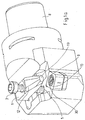
- FIGS. 1 a and 1b show two tool systems according to the invention.
- the carrier tool is in each case characterized, which has a recess for receiving a cutting plate 2.
- the cutting plates 2 according to the FIGS. 1a and 1b have a circular clamping trough 9 in which a spherical or circular elevation 30 is arranged. The highest point of the elevation 30 is disposed above the bottom of the clamping trough 9 and below the cutting plate top, or below the rake face.
- FIG. 1a Preferred is as in FIG. 1a to see, coaxially to the first clamping trough 9, a second clamping trough 10 is arranged, wherein the first clamping trough 9 are lower than the second Sparinmulde 10 and both 9, 10 are arranged lower than the cutting plate top.
- the height distance of the first clamping recess 9 to the second clamping recess 10 is always the same, even with a grinding or lapping processing of the cutting plate top.
- a clamping element 1 is fixed on the carrier tool 8 via a clamping screw 3.
- the clamping screw 3 passes through the clamping element 1 and is screwed into a clamping element bore 5 on the carrier tool 8.
- the tip of the clamping element 1 presses on the cutting plate 2.
- a cutting plate 2 with a clamping recess 9 is arranged on the cutting plate 2 facing bottom of the clamping element 1 as a cam or sickle shaped engaging element 11.
- This engaging element 11 engages in the clamping recess 9 and thereby anchors it on the carrier tool 8.
- the engaging element can have any conceivable shape beyond the shape as a cam or sickle in principle, also a clamping element. 1 without engaging element (ie smooth) is possible. When using a clamping element 1 without engaging element but no retraction of the insert is given.
- the tensioning element 1 (see FIGS FIGS. 2a . 2b, 2c ) guided on both sides on the carrier tool 8.
- guide surfaces 14 are arranged on the one hand in the carrier tool 8 as a guide, which are closely tolerated and the clamping element areally lead to the contour transition 12.
- FIG. 2a is given the guide length L and the guide width B and their range. [L] is preferably between 10 - 22 mm (depending on size) and [B] between 10 - 20 mm (depending on size).
- the tolerance of the guide width [B] on the carrier tool 8 is B ⁇ 0.025 and the tolerance of the width of the clamping element B is ⁇ 0.05.
- Figure 2c particularly shows the guide surface 14.
- the guide is thus very close to the clamping element tip 13. This ensures a secure engagement of the clamping element contour or the engaging element 11 in the first clamping recess 9 of the cutting plate 2.
- the position of the clamping element 1 is thus independent of the tool position in space (machine) always the same (no twisting), bringing a change of the cutting plate z. B. overhead (based on the tool) is easily carried out.
- FIG. 3 illustrates that positioning in the axial pulling direction of the clamping element 1 from the center of the clamping element head to the center of the cutting insert (WSP) is given automatically due to the dimensions of the bore in the clamping element and the clamping element screw.
- WSP cutting insert
- the high process reliability is in addition to the lateral guidance mainly by the withdrawal of the clamping element by means of retraction slope 15, see FIG. 3 or FIG. 4a ), the positive connection between clamping element contour or engaging element and cutting insert (WSP) and the pressing of the engaging element 11 (clamping element nose) in front of the center of the clamping trough 9 ( see, eg Fig. 1a ) achieved. Due to these circumstances, the insert is pulled against rotation in the insert seat ( FIG. 4a ).
- in front of the center of the clamping trough 9 is meant that the engaging element seen from the cutting edge, in front of the center of the clamping trough 9 in this form-fitting engages and thereby a "beaking" of the cutting plate is excluded.
- FIG. 5 illustrates that the withdrawal of the clamping element 1 via the emergence of the clamping element bore 5 ( Fig. 6 ) is limited to the screw shaft. This slipping out of the clamping element 1 is prevented from the insert recess 9 and the whole system clamping element - screw - Tool is tense.
- the cutting plate 2 sits on a support member 27 (support plate) and the support member 27 is anchored with a screw 28 on the carrier tool 8.
- the tool system according to the invention is designed with a ratio of 1: 1.7 (see FIG. 6 ). This ensures that 37% of the initiated screw force act as closing force on the cutting plate.
- the selected center distance dimension "X" (see FIG. 6 ) is the result of the consideration with a minimum number of clamping element sizes (minimization of variants) to clamp all relevant for the tool system and in the market usual cutting plate geometries and sizes technically flawless in the tool system according to the invention.
- the length (lever) ratio is at all 1: 1.7.
- the distance F screw to F screw is 1, then according to the invention the distance F screw to F WSPS screw is preferably 1.7. This shows FIG. 6 ,
- the clamping screw 3 is at the end of the screw (see FIG. 7 ) formed with an external hexagon 29 to allow the insert exchange a loosening of the clamping screw 3 from below. This is necessary if the tool is located, for example, overhead in the machine. For M6, a wrench size of SW 4 was calculated. M6 would also be possible a SW4,5. A SW 5.5 was chosen for M8. M8 could be SW5 to SW6.
- the clamping element bore 5 extends through the carrier tool 8, so that the screw end of the clamping screw 3 can be reached.
- a cooling medium supply is integrated in the carrier tool 8.
- the cooling medium supply is in the FIGS. 8a to 8d shown.
- the cooling medium supply is integrated in the two lateral clamping element guides 19 ( FIGS. 8a and 8b ).
- the cooling medium is thereby brought very close targeted to the cutting process.
- the sliding of the chips is made possible by means of a ramp 20 with transition radii.
- the ramp angle a of the ramp 20 ( FIG. 8d ) to the insert top is between 3 and 10 degrees.
- a snagging (flow) chips, as was often seen earlier in kuhfstoffen is thus excluded.
- the height H of the ramp 20 is preferably between 4 and 8 mm ( FIG. 8c ).
- the size of the outlet opening and hole for the cooling medium is depending on the tool size of 2 to 10 mm.
- a thread for a possible screw plug is arranged at the outlet opening.
- a nozzle 31 (see FIG. 8e ) with cone-shaped tip and a centric bore.
- the bore diameter varies from ⁇ 1 mm to 6 mm.
- the nozzles are used when the coolant pressure is ⁇ 20 bar and the "original" coolant hole is prone to clogging (clogging).
- An increase in the exit velocity of the cooling medium is also achieved here, provided that the cooling medium volume is sufficient in the machining process.
- FIG. 9a shows the tool system as a monobloc tool and FIG. 9b as a tool with adapter.
- the monobloc tool according to FIG. 9a is with the tool system according to FIG. 1 a identical.
- FIGS. 10a to 10d explained in more detail.
- the adapter 7 integrates all functions for process-reliable clamping of the cutting plate 2 in itself.
- the adapter 7 is fastened to the carrier tool 8 with screws and therefore has two screw holes 21. In addition, it has a bore 22 for the clamping screw 3.
- the adapter 7 has lateral adapter guides 23, an adapter retraction slope 24 and possibly a cooling medium supply similar to the monoblock tool.
- the outlet opening 25 and bore of the cooling medium supply is depending on the adapter size of 2 mm to 5 mm.
- the cooling medium is supplied through the adapter guides 23.
- the adapter retraction slope 24 is arranged at the rear end of the adapter.
- the height of the adapter is 10 mm and the height of the adapter guides 23 is 6 mm.
- the dimensions of a preferred embodiment are the Figures 10c and 10d refer to.
- insert seat walls 26 are arranged, against which the cutting plates abut, like this FIG. 10c shows.
- the lateral guides and the retraction slope (20 degrees) are deliberately integrated on the adapter (and not on the tool) so that the alignment / axiality / parallelism of the clamping element and the center of the insert coincide exactly.
- the adapter is made of hot-work steel.
Landscapes
- Engineering & Computer Science (AREA)
- Mechanical Engineering (AREA)
- Cutting Tools, Boring Holders, And Turrets (AREA)
- Processing Of Meat And Fish (AREA)
Description
- Die Erfindung betrifft ein spanabhebendes Werkzeugsystem gemäß dem Oberbegriff des Anspruchs 1 mit einem Trägerwerkzeug, einer Schneidplatte mit einer Spannmulde und einem Spannelement mit zugehöriger Spannschraube, wobei an der zur Schneidplatte gewandten Unterseite des Spannelements ein Eingreifelement angeordnet ist, das im eingebauten Zustand mit der Spannmulde in spannender Berührung steht und die Schneidplatte dadurch verankert und das Spannelement über eine Schräge so geführt ist, dass beim Anziehen der Spannschraube das Spannelement in Spannrichtung gezogen wird. Ein solches Werkzeugsystem ist aus der
EP-A2-0 402 934 bekannt. - Aus der
WO 2007080151 A1 ist ein spanabhebendes Werkzeugsystem bekannt, welches im Wesentlichen aus einem Trägerwerkzeug besteht, welches eine Ausnehmung zur Aufnahme einer Schneidplatte aufweist. Die Schneidplatte ist mit einer Spannmulde versehen. Die Schneidplatte wird von einem Spannelement im Trägerwerkzeug gehalten. Das Spannelement ist wiederum über eine Spannschraube auf dem Trägerwerkzeug befestigt. An der zur Schneidplatte gewandten Unterseite des Spannelements ist ein Eingreifelement angeordnet, das mit der Spannmulde in spannender Berührung steht und die Schneidplatte dadurch auf dem Trägerwerkzeug verankert. Das Spannelement ist über eine Schräge auf dem Trägerwerkzeug geführt, so dass beim Anziehen der Spannschraube das Spannelement hin zum Trägerwerkzeug gezogen wird. - Der Erfindung liegt die Aufgabe zugrunde, ein Werkzeugsystem nach dem Oberbegriff des Anspruchs 1 so zu verbessern, dass es auch für die Anwendung in der Dreh-Schruppbearbeitung mit Schnittdaten von bis zu vc 3000 m/min, ap bis 10 mm (abhängig von Plattengröße und Schneidplattengeometrie und dem zu bearbeitenden Werkstoff) und einem Vorschub f bis 1,0 mm und ggf. höher geeignet ist. Es soll außerdem eine hohe Prozesssicherheit gewährleitet werden. Erfindungsgemäß wird diese Aufgabe durch die Merkmale des Anspruchs 1 gelöst.
-
- a. dass das Spannelement in einer Nut mit parallelen Spannelementführungen angeordnet ist, in der das Spannelement in Spannrichtung verschiebbar geführt ist, wobei das Spannelement zwei parallele Führungsflächen aufweist, die an den Spannelementführungen flächig anliegenden, so dass das Spannelement beidseitig in der Nut geführt ist,
- b. dass im Spannelement eine Spannelementbohrung für die Spannschraube angeordnet ist und im eingespannten Zustand der Schneidplatte die zur Schneidplatte gewandte Wandung der Spannelementbohrung an der Spannschraube anliegt und
- c. dass das Eingreifelement, von der Schneidkante der Schneidplatte aus gesehen, vor der Mitte der Spannmulde in diese formschlüssig eingreift,
- Durch die beidseitige Führung des Spannelements ist ein sicheres Eingreifen der Spannelementkontur bzw. des Eingreifelements in die Spannmulde der Schneidplatte gewährleistet. Die Lage des Spannelementes ist somit auch unabhängig von der Werkzeugläge im Raum (Maschine) immer dieselbe (kein Verdrehen), womit ein Wechsel der Schneidplatte z. B. auch Überköpf (bezogen auf das Werkzeug) problemlos durchführbar ist. Das Anliegen der Wandung der Spannelementbohrung an der Spannschraube ist ein wichtiges Merkmal der Erfindung, da dadurch Δ2 gleich Null ist (siehe
Figur 3 ) und der Abstand von der Längsachse der Spannschraube zum Zentrum der Schneidplatte immer gleich groß ist. Das Eingreifelement an der Unterseite des Spannelements greift dadurch an genau definierter Stelle in die Spannmulde ein. Dies ist extrem wichtig, da sonst undefinierte Kräfte auf die Schneidplatte einwirken. Die hohe Prozesssicherheit wird ferner durch das Drücken des Eingreifelements (Spannelementnase) vor der Mitte der Spannmulde erzielt. Hierdurch wird ein Aufschnäbeln der Schneidplatte ausgeschlossen Mit "vor der Mitte der Spannmulde" ist gemeint, dass das Eingreifelement von der Schneidkante aus gesehen, vor der Mitte der Spannmulde in diese formschlüssig eingreift. - Erfindungsgemäß ist das Werkzeugsystem bevorzugt als Monoblockwerkzeug oder als Werkzeug mit Adapter auszubilden.
- Wenn das Werkzeugsystem als Monoblockwerkzeug ausgebildet ist, ist bevorzugt die Schneidplatte in einer Ausnehmung des Trägerwerkzeugs angeordnet, das Spannelement ist über die Spannschraube auf dem Trägerwerkzeug befestigt, ist die Schräge auf dem Trägerwerkzeug angeordnet und wird beim Anziehen der Spannschraube das Spannelement in Spannrichtung hin zum Trägerwerkzeugs gezogen wird. Diese Ausführungsform ist in
Figur 9a gezeigt. - Wenn das Werkzeugsystem mit Adapter ausgebildet ist, ist bevorzugt der Adapter in einer Adapternut auf dem Trägerwerkzeug befestigt, ist im Adapter die Nut mit den parallelen Spannelementführungen angeordnet, ist in der Nut das Spannelement beidseitig geführt und sind im Adapter eine durchgehende Bohrung für die Spannschraube und durchgehende Bohrungen zur Befestigung des Adapters auf dem Trägerwerkzeugs angeordnet, liegt die Schneidplatte in einer an die Geometrie der Schneidplatte angepasste Aufnahme im Adapter an und ist die Schräge am Adapter und nicht am Trägerwerkzeugs angeordnet. Die seitlichen Führungen und die Schräge bzw. Rückzugsschräge (siehe später) sind bewusst am Adapter integriert (und nicht am Trägerwerkzeug damit die Flucht/Axialität/Parallelität von Spannelement und Schneidplattenmitte exakt übereinstimmen. Der Adapter wird bevorzugt aus Warmarbeitsstahl gefertigt.
- Alle nachfolgenden Ausgestaltungen lassen sich sowohl für das Monoblockwerkzeug als auch für das Werkzeug mit Adapter verwenden.
- Bevorzugt beträgt die Toleranz der Führungsbreite (B) der Nut, d.h. die Toleranz des Abstands der Spannelementführungen voneinander B ± 0,025 und beträgt die Toleranz der Breite des Spannelements, d.h. die Toleranz des Abstands der Führungsflächen am Spannelement voneinander B ± 0,05. Durch die eng tolerierte Führung wird auch bei schweren Bearbeitungen und evtl. kurzfristig auftretenden Überlastungen das Spannelement seine Lage beibehalten. Im Falle eines "Crashes" kann damit unter Umständen größerer Schaden vom Trägerwerkzeug und Werkstück abgewendet werden.
- Bevorzugt ist am hinteren Ende des Spannelements, von der Schneidplatte aus gesehen, eine die Schräge bildende Rückzugsschräge angeordnet. und befindet sich beim Monoblockwerkzeug auf dem Trägerwerkzeug eine an die Rückzugsschräge angepasste Abrutschschräge und befindet sich beim Werkzeugsystem mit Adapter eine Rückzugsschräge am hinteren Ende des Adapters und liegt der Winkel der Rückzugsschrägen und der Abrutschschrägen zur Horizontalen bevorzugt zwischen 15 bis 25 Grad, besonders bevorzugt bei 20 Grad. Eine Positionierung in axialer Zugrichtung des Spannelementes vom Zentrum des Spannelementkopfes zum Zentrum der Schneidplatte ist dadurch zusammen mit der Anlage der Spannelementschraube an der Spannelemeritbohrung aufgrund der Abmaße über die Bohrung im Spannelement automatisch gegeben.
- Bevorzugt teilt sich die Spannkraft FSchraube der Spannschraube auf das Spannelement auf die Schrägen FASchraube und auf die Schneidplatte FWSPSchraube auf, wobei FSchraube = FASchraube + FWSPSchraube und FASchraube = FWSPSchraube * X, wobei X zwischen 1,6 und 1,8 bevorzugt bei 1,7 liegt. Wichtig für ein prozesssicheres Spannen der Schneidplatte ist das gewählte Längen- (Hebel-) verhältnis am Spannelement. Das erfindungsgemäße Werkzeugsystem ist bevorzugt mit einem Verhältnis von 1 : 1,7 ausgelegt (siehe
Figur 6 ). Damit wird erreicht, dass 37% der eingeleiteten Schraubenkraft als Schließkraft auf die Schneidplatte wirken. - Bevorzugt ist die Spannschraube am Schraubenende mit einem Außensechskant ausgebildet. Die Spannelementbohrung durchragt das Trägerwerkzeug so, dass das Schraubenende der Spannschraube erreichbar ist. Hierdurch ist beim Schneidplattenwechsel ein Lösen der Spannschraube von unten ermöglicht. Dies ist notwendig, wenn das Werkzeug z. B. über Kopf in der Maschine steht.
- Bevorzugt ist in den Spannelementführungen der Nut eine Kühlmediumzuführung integriert. Bevorzugt sind die Spannelementführungen als zur Schneidplatte hin abfallende Rampen ausgebildet und führen über zwei Übergangsradien R3, R5 bis zur Schneidplattenoberseite. Die Austrittsöffnung der Kühlmediumzuführung ist zwischen den Radien R3 und R5 angeordnet. Kühlmittel verlängert die Lebensdauer des Werkzeugsystems und die Standzeit der Schneidplatte. Außerdem verbessert es die Werkstückoberfläche.
- Bevorzugt beträgt der Rampenwinkel α der Rampe zu der Schneidplattenoberseite zwischen 3 und 10 Grad. Hierdurch werden die anfallenden Späne besser abgeleitet.
- Bevorzugt sind für spezielle Anwendungen an der Austrittsöffnung ein Gewinde für eine Verschlussschraube oder eine Düse angeordnet.
- Bevorzugt ist die Verwendung dieses Werkzeugsystems für die Dreh-Schruppbearbeitung mit Schnittdaten von bis zu vc = 3.000 m/min, ap bis 10 mm (abhängig von Plattengröße und Schneidplattengeometrie und dem zu bearbeitenden Werkstoff) und einem Vorschub f bis 1,0 mm.
- In der gesamten Beschreibung wird von einer Schneidplatte gesprochen, obwohl es sich bevorzugt um eine Wendeschneidplatte handelt.
- Nachfolgend wird die Erfindung anhand von Figuren weiter erläutert.
- In den
Figuren 1 a und 1 b sind zwei erfindungsgemäße Werkzeugsysteme gezeigt. - Mit dem Bezugszeichen 8 ist jeweils das Trägerwerkzeug gekennzeichnet, welches eine Ausnehmung zur Aufnahme einer Schneidplatte 2 aufweist. Die Schneidplatten 2 gemäß der
Figuren 1a und1b weisen eine kreisförmige Spannmulde 9 auf in der eine kugel- bzw. kreisförmige Erhebung 30 angeordnet ist. Der höchste Punkt der Erhebung 30 ist oberhalb des Bodens der Spannmulde 9 und unterhalb der Schneidplattenoberseite, bzw. unterhalb der Spanfläche angeordnet. - Bevorzugt ist, wie in
Figur 1a zu sehen, koaxial zur ersten Spannmulde 9 eine zweite Spannmulde 10 angeordnet, wobei die erste Spannmulde 9 tiefer als die zweite Sparinmulde 10 und beide 9, 10 tiefer als die Schneidplattenoberseite angeordnet sind. Hierdurch ist der Höhenabstand der ersten Spannmulde 9 zur zweiten Spannmulde 10 immer derselbe, auch bei einer Schleif- oder Läppbearbeitung der Schneidplattenoberseite. - Zur Befestigung der Schneidplatte 2 auf dem Trägerwerkzeug 8 ist ein Spannelement 1 auf dem Trägerwerkzeug 8 über eine Spannschraube 3 befestigt. Die Spannschraube 3 durchragt das Spannelement 1 und ist in eine Spannelementbohrung 5 auf dem Trägerwerkzeug 8 eingeschraubt.
- Beim Eindrehen der Spannschraube 3 drückt die Spitze des Spannelement 1 auf die Schneidplatte 2. Bei Verwendung einer Schneidplatte 2 mit einer Spannmulde 9 ist an der zur Schneidplatte 2 gewandten Unterseite des Spannelements 1 ein als Nocken oder als Sichel ausgeformtes Eingreifelement 11 angeordnet. Dieses Eingreifelement 11 greift in die Spannmulde 9 ein und verankert diese dadurch auf dem Trägerwerkzeug 8. Das Eingreifelement kann über die Form als Nocken oder Sichel hinaus im Prinzip jede denkbare Gestalt haben, auch ein Spannelement 1 ohne Eingreifelement (also Glatt) ist möglich. Bei Verwendung eines Spannelements 1 ohne Eingreifelement ist aber kein Rückzug der Wendeschneidplatte gegeben.
- Erfindungsgemäß ist das Spannelement 1 (siehe die
Figuren 2a ,2b, 2c ) beidseitig auf dem Trägerwerkzeug 8 geführt. Zur Führung sind einerseits im Trägerwerkzeug 8 als Führung eine Nut 6 und andererseits am Spannelement 1 Führungsflächen 14 angeordnet, die eng toleriert sind und das Spannelement flächig bis zum Konturübergang 12 führen. InFigur 2a ist die Führungslänge L und die Führungsbreite B und deren Bereich angegeben. [L] liegt bevorzugt zwischen 10 - 22 mm (abhängig von Baugröße) und [B] zwischen 10 - 20 mm (abhängig von Baugröße). Die Toleranz der Führungsbreite [B] auf dem Trägerwerkzeug 8 beträgt B ± 0,025 und die Toleranz der Breite des Spannelements B ± 0,05.Figur 2c zeigt besonders die Führungsfläche 14. - Die Führung erfolgt dadurch sehr nahe bis zur Spannelementspitze 13. Dadurch ist ein sicheres Eingreifen der Spannelementkontur bzw. des Eingreifelements 11 in die erste Spannmulde 9 der Schneidplatte 2 gewährleistet. Die Lage des Spannelementes 1 ist somit auch unabhängig von der Werkzeuglage im Raum (Maschine) immer dieselbe (kein Verdrehen), womit ein Wechsel der Schneidplatte z. B. auch Überkopf (bezogen auf das Werkzeug) problemlos durchführbar ist.
- Durch die eng tolerierte Führung wird auch bei schweren Bearbeitungen und evtl. kurzfristig auftretenden Überlastungen das Spannelements 1 seine Lage beibehalten. Im Falle eines "crashs" kann damit u. U. größerer Schaden vom Werkzeug und Werkstück abgewendet werden.
-
Figur 3 veranschaulicht, dass eine Positionierung in axialer Zugrichtung des Spannelementes 1 vom Zentrum des Spannelementkopfes zum Zentrum der Schneidplatte (WSP) aufgrund der Abmaße über die Bohrung im Spannelement und der Spannelementschraube automatisch gegeben ist. Dies wird dadurch erreicht, dass am hinteren Ende des Spannelements 1, von der Schneidplatte 2 aus gesehen, eine Rückzugsschräge 4 angeordnet ist und sich auf dem Spannelement 1 eine an die Rückzugsschräge 4 angepasste Abrutschschräge 15 befindet. Wird das Spannelement 1 mit der Spannschraube 3 befestigt, rutscht die Abrutschschräge 15 auf der Rückzugsschräge 4 ab, bis die zur Schneidplatte 2 gewandte Wandung der Spannelementbohrung 5 an der Spannschraube 3 anliegt. Dieses Anliegen der Wandung der Spannelementbohrung 5 an der Spannschraube 3 ist ein wichtiges Merkmal der Erfindung, da dadurch Δ2 gleich Null ist (sieheFigur 3 ) und der Abstand 16 von der Längsachse 17 der Spannschraube 3 zum Zentrum 18 der Schneidplatte 2 immer gleich groß ist. Das Eingreifelement 11 an der Unterseite des Spannelement 1 greift dadurch an genau definierter Stelle in die Spannmulde ein. Dies ist extrem wichtig, da sonst undefinierte Kräfte auf die Schneidplatte 2 einwirken. Die Winkel von Rückzugsschräge 4 und Abrutschschräge 15 liegen bevorzugt bei 20 Grad zur Horizontalen. - Die hohe Prozesssicherheit wird neben der seitlichen Führung hauptsächlich durch den Rückzug des Spannelementes mittels Rückzugsschräge 15, siehe
Figur 3 oderFigur 4a ), dem Formschluss zwischen Spannelementkontur bzw. Eingreifelement und Schneidplatte (WSP) sowie das Drücken des Eingreifelements 11 (Spannelementnase) vor der Mitte der Spannmulde 9 (siehe z.B.Fig. 1a ) erzielt. Durch diese Gegebenheiten wird die WSP verdrehsicher in den Plattensitz gezogen (Figur 4a ). Mit "vor der Mitte der Spannmulde 9" ist gemeint, dass das Eingreifelement von der Schneidkante aus gesehen, vor der Mitte der Spannmulde 9 in diese formschlüssig eingreift und dadurch ein "Aufschnäbeln" der Schneidplatte ausgeschlossen ist. -
Figur 5 veranschaulicht, dass der Rückzug des Spannelementes 1 über das Auflaufen der Spannelementbohrung 5 (Fig. 6 ) auf den Schraubenschaft begrenzt ist. Damit wird ein Herausgleiten des Spannelementes 1 aus der Schneidplattenmulde 9 verhindert und das ganze System Spannelement - Schraube - Werkzeug verspannt sich. Die Schneidplatte 2 sitzt auf einem Stützelement 27 (Stützplatte) auf und das Stützelement 27 ist mit einer Schraube 28 auf dem Trägerwerkzeug 8 verankert. - Elementar wichtig für ein prozesssicheres Spannen der Schneidplatte 2 ist das gewählte Längen- (Hebel-) verhältnis am Spannelement. Das erfindungsgemäße Werkzeugsystem ist mit einem Verhältnis von 1 : 1,7 ausgelegt (siehe
Figur 6 ). Damit wird erreicht, dass 37% der eingeleiteten Schraubenkraft als Schließkraft auf die Schneidplatte wirken. - Das gewählte Achsabstandsmaß "X" (siehe
Figur 6 ) ist das Resultat aus der Überlegung mit einer minimalen Anzahl an Spannelementgrößen (Variantenminimierung) alle die für das Werkzeugsystem relevanten und im Markt üblichen Schneidplattengeometrien und größen technisch einwandfrei im erfindungsgemäßen Werkzeugsystem zu spannen. Es sind 3 Spannelementgrößen mit 3 unterschiedlichen Achsabstandsmaßen (X=13,3 mm, X=16,15 mm und X= 21,5 mm) als vorteilhaft entwickelt worden. Diese decken alle WSP-Geometrien von Inkreis 9,52 mm bis 25,40 mm ab. Das Längen- (Hebel-) verhältnis ist bei allen 1 : 1,7. - Würde man die Väriantenminimierung nicht berücksichtigen, dann wäre ein Verhältnis kleiner 1,7 bis 1,0 technisch besser. Damit würde im Verhältnis 1 : 1 die Hälfte der eingeleiteten Schraubenkraft auf die Schneidplatte drücken. Der Bereich ab 1,7 bis 2,2 ist technisch möglich. Aber je größer das Verhältnis desto geringer ist die Kraft, die auf die Schneidplatte wirkt. Wenn beispielsweise die Spannschraube 3 mit einer Kraft Fschraube = 10.000 N das Spannelement 1 beaufschlagt, dann sollte sich die Kraft erfindungsgemäß bevorzugt zu FASchraube = 6.300 N auf die Schräge 15 und zu FWSPSSchraube = 3.700 N auf die Schneidplatte 2 aufteilen, da 6.300 N = 3.700 N * 1,7.
- Wenn der Abstand FASchraube zu FSchraube 1 ist, dann beträgt erfindungsgemäß der Abstand FSchraube zu FWSPSSchraube bevorzugt 1,7. Dies zeigt
Figur 6 . - Bevorzugt ist auch der Bereich 1: 1,6 bis 1 : 1,8.
Die Spannschraube 3 ist am Schraubenende (sieheFigur 7 ) mit einem Außensechskant 29 ausgebildet um beim Schneidplattenwechsel ein Lösen der Spannschraube 3 von unten zu ermöglichen. Dies ist notwendig, wenn das Werkzeug z.B. über Kopf in der Maschine steht. Für M6 wurde eine Schlüsselweite von SW 4 errechnet. Möglich wäre bei M6 auch eine SW4,5. Für M8 wurde eine SW 5,5 gewählt. Möglich wäre bei M8 der Bereich SW5 bis SW6. Die Spannelementbohrung 5 durchragt das Trägerwerkzeug 8, so dass das Schraubenende der Spannschraube 3 erreichbar ist. - Nachfolgend die Werkstoffe und Werkzeugaufnahmen:
- Das Trägerwerkzeug 8 besteht bevorzugt aus den Werkstoffen Vergütungsstahl oder Warmarbeitsstahl
- Das Spannelement 1 besteht bevorzugt aus den Werkstoffen:
- Stahl 500 - 750 HV
- Hartmetall 850 - 1250 HV
- Keramik 1250 - 1650 HV
- Das Spannelement ist konstruktiv auch als Verbundwerkstoff ausführbar in den Varianten:
- Trägerwerkzeug aus Stahl und Abdeckung aus Hartmetall
- Grundträger aus Stahl und Abdeckung aus Keramik
- Es sind alle gängigen Werkzeugaufnahme-Systeme wie CMS, HSK, KM, FTC, VDI, SK xxx möglich.
- Das erfindungsgemäße Werkzeugsystem ist auch für alle gängigen Werkzeugtypen anwendbar wie Schaftwerkzeuge, Bohrstangen, Kurzklemmhalter.
- In einer vorteilhaften Ausführungsform der Erfindung ist im Trägerwerkzeug 8 eine Kühlmediumzuführung integriert. Die Kühlmediumzuführung ist in den
Figuren 8a bis 8d gezeigt. Die Kühlmediumzuführung ist in den beiden seitlichen Spannelementführungen 19 integriert (Figur 8a und 8b ). Das Kühlmedium wird dadurch sehr nahe zielgerichtet an den Schneidprozess herangebracht. Das Abgleiten der Späne wird mittels einer Rampe 20 mit Übergangsradien ermöglicht. Der Rampenwinkel a der Rampe 20 (Figur 8d ) zu der Schneidplattenoberseite liegt zwischen 3 und 10 Grad. Ein Verhaken von (Fließ-) Spänen, wie dies früher häufig an Kühfmittelrohren zu sehen war, ist damit ausgeschlossen. Die Höhe H der Rampe 20 liegt bevorzugt zwischen 4 und 8 mm (Figur 8c ). - Die Größe der Austrittsöffnung und Bohrung für das Kühlmedium geht je nach Werkzeugröße von 2 bis 10 mm. An der Austrittsöffnung ist ein Gewinde für eine mögliche Verschlussschraube angeordnet.
- Es besteht allerdings auch die Möglichkeit, an der Austrittsöffnung eine Düse 31 (siehe
Figur 8e ) mit kegelförmiger Spitze und einer zentrischen Bohrung einzudrehen. Der Bohrungsdurchmesser variiert je nach Baugröße des Werkzeugs von Ø 1 mm - 6 mm. Die Düsen werden eingesetzt, wenn der Kühlmediumdruck < 20 bar ist und die "originale" Kühlmediumbohrung zum Verschmutzen (Verstopfen) neigt. Auch eine Erhöhung der Austrittsgeschwindigkeit des Kühlmediums wird hierduch erreicht, sofern das Kühlmediumvolumen am Bearbeitungsprozess ausreicht. - Das erfindungsgemäße Werkzeugsystem ist sowohl als Monoblockwerkzeug als auch als Werkzeug mit Adapter vorgesehen.
Figur 9a zeigt das Werkzeugsystem als Monoblockwerkzeug undFigur 9b als Werkzeug mit Adapter. Das Monoblockwerkzeug gemäßFigur 9a ist mit dem Werkzeugsystem gemäßFigur 1 a identisch. Nachfolgend wird das Werkzeugsystem gemäßFigur 9b anhand vonFigur 10a bis 10d näher erläutert. - Der Adapter 7 (siehe die
Figuren 10a bis 10d ) integriert alle Funktionen zum prozesssicheren Spannen der Schneidplatte 2 in sich. Der Adapter 7 wird am Trägerwerkzeug 8 mit Schrauben befestigt und weist daher zwei Schraubenbohrungen 21 auf. Außerdem verfügt er über eine Bohrung 22 für die Spannschraube 3. Damit das Spannelement 1 geführt ist, weist der Adapter 7 seitliche Adapterführungen 23, eine Adapter-Rückzugsschräge 24 und ggf. eine Kühlmediumzufuhr ähnlich dem Monoblockwerkzeug auf. Die Austrittsöffnung 25 und Bohrung der Kühlmediumzufuhr beträgt je nach Adaptergröße von 2 mm bis 5 mm. Die Kühlmediumzufuhr erfolgt durch die Adapterführungen 23. Die Adapter-Rückzugsschräge 24 ist am hinteren Ende des Adapters angeordnet. Die Höhe des Adapters beträgt 10 mm und die Höhe der Adapterführungen 23 beträgt 6 mm. Die Maße einer bevorzugten Ausführungsform sind denFiguren 10c und 10d zu entnehmen. An der zur Schneidplatte gewandten Seite des Adapters 7 sind je nach der Form der Schneidplatten Plattensitzwände 26 angeordnet, an denen die Schneidplatten anliegen, wie diesFigur 10c zeigt. - Die seitlichen Führungen und die Rückzugsschräge (20 Grad) sind bewusst am Adapter integriert (und nicht am Werkzeug) damit die Flucht/Axialität/Parallelität von Spannelement und Schneidplattenmitte exakt übereinstimmen. Der Adapter wird aus Warmarbeitsstahl gefertigt.
Claims (12)
- Spanabhebendes Werkzeugsystem mit einem Trägerwerkzeug (8), einer Schneidplatte (2) mit einer Spannmulde (9) und einem Spannelement (1) mit zugehöriger Spannschraube (3), wobei an der zur Schneidplatte (2) gewandten Unterseite des Spannelements (1) ein Eingreifelement (11) angeordnet ist, das im eingebauten Zustand mit der Spannmulde (9) in spannender Berührung steht und die Schneidplatte (2) dadurch verankert und das Spannelement (1) über eine Schräge so geführt ist, dass beim Anziehen der Spannschraube (3) das Spannelement (1) in Spannrichtung gezogen wird, dadurch gekennzeichnet,d. dass das Spannelement (1) in einer Nut (6) mit parallelen Spannelementführungen (19) angeordnet ist, in der das Spannelement (1) in Spannrichtung verschiebbar geführt ist, wobei das Spannelement (1) zwei parallele Führungsflächen (14) aufweist, die an den Spannelementführungen (19) flächig anliegenden, so dass das Spannelement (1) beidseitig in der Nut (6) geführt ist,e. dass im Spannelement (1) eine Spannelementbohrung (5) für die Spannschraube (3) angeordnet ist und im eingespannten Zustand der Schneidplatte (2) die zur Schneidplatte (2) gewandte Wandung der Spannelementbohrung (5) an der Spannschraube (3) anliegt undf. dass das Eingreifelement (11), von der Schneidkante der Schneidplatte (2) aus gesehen, vorder Mitte der Spannmulde (9) in diese formschlüssig eingreift.
- Werkzeugsystem nach Anspruch 1, dadurch gekennzeichnet, dass das Werkzeugsystem als Monoblockwerkzeug ausgebildet ist, wobei die Schneidplatte (2) in einer Ausnehmung des Trägerwerkzeugs (8) angeordnet ist, das Spannelement (1) über die Spannschraube (3) auf dem Trägerwerkzeug (8) befestigt ist, die Schräge auf dem Trägerwerkzeug (8) angeordnet ist und beim Anziehen der Spannschraube (3) das Spannelement (1) in Spannrichtung hin zum Trägerwerkzeug (8) gezogen wird.
- Werkzeugsystem nach Anspruch 1, dadurch gekennzeichnet, dass das Werkzeugsystem mit Adapter (7) ausgebildet ist, wobei der Adapter (7) in einer Adapternut (32) auf dem Trägerwerkzeug (8) befestigt ist, im Adapter (7) die Nut (6) mit den parallelen Spannelementführungen (19) angeordnet ist, in der Nut (6) das Spannelement (1) beidseitig geführt ist und im Adapter (7) eine durchgehende Bohrung (22) für die Spannschraube (3) und durchgehende Bohrungen (21) zur Befestigung des Adapters (7) auf dem Trägerwerkzeug (8) angeordnet sind, die Schneidplatte (2) in einer an die Geometrie der Schneidplatte (2) angepasste Aufnahme im Adapter (7) anliegt und die Schräge am Adapter (7) und nicht am Trägerwerkzeug (8) angeordnet ist.
- Werkzeugsystem nach einem der Ansprüche 1 bis 3, dadurch gekennzeichnet, dass die Toleranz der Führungsbreite (B) der Nut (6), d.h. die Toleranz des Abstands der Spannelementführungen (19) voneinander B ± 0,025 beträgt und die Toleranz der Breite des Spannelements (1), d.h. die Toleranz des Abstands der Führungsflächen (14) am Spannelement (1) voneinander B ± 0,05 beträgt.
- Werkzeugsystem nach einem der Ansprüche 1 bis 4, dadurch gekennzeichnet, dass am hinteren Ende des Spannelements (1), von der Schneidplatte (2) aus gesehen, eine die Schräge bildende Rückzugsschräge (4) angeordnet ist und sich beim Monoblockwerkzeug auf dem Trägerwerkzeug (8) eine an die Rückzugsschräge (4) angepasste Abrutschschräge (15) befindet und sich beim Werkzeugsystem mit Adapter (7) eine Rückzugsschräge (24) am hinteren Ende des Adapters (7) befindet und der Winkel der Rückzugsschrägen (24) und der Abrutschschrägen (15) zur Horizontalen bevorzugt zwischen 15 bis 25 Grad, besonders bevorzugt bei 20 Grad liegt.
- Werkzeugsystem nach einem der Ansprüche 1 bis 5, dadurch gekennzeichnet, dass sich die Spannkraft FSchraube der Spannschraube (3) auf das Spannelement (1) auf die Schrägen FASchraube und auf die Schneidplatte (2) FWSPSchraube aufteilt, wobei FSchraube = FASchraube + FWSPSchraube und
FASchraube = FwSPSchraube * X
wobei X zwischen 1,6 und 1,8 bevorzugt bei 1,7 liegt. - Werkzeugsystem nach einem der Ansprüche 1 bis 6, dadurch gekennzeichnet, dass die Spannschraube (3) am Schraubenende mit einem Außensechskant (29) ausgebildet ist.
- Werkzeugsystem nach einem der Ansprüche 1 bis 7, dadurch gekennzeichnet, dass in den Spannelementführungen (19) der Nut (6) eine Kühlmediumzuführung integriert ist.
- Werkzeugsystem nach Anspruch 8, dadurch gekennzeichnet, dass die Spannelementführungen (19) als zur Schneidplatte (2) hin abfallende Rampen (20) ausgebildet sind und über zwei Übergangsradien R3, R5 bis zur Schneidplattenoberseite führen und die Austrittsöffnung (25) der Kühlmediumzuführung zwischen den Radien R3 und R5 angeordnet ist.
- Werkzeugsystem nach Anspruch 9, dadurch gekennzeichnet, dass der Rampenwinkel α der Rampe (20) zu der Schneidplattenoberseite zwischen 3 und 10 Grad beträgt.
- Werkzeugsystem nach Anspruch 9 oder 10, dadurch gekennzeichnet, dass an der Austrittsöffnung (25) ein Gewinde für eine Verschlussschraube oder eine Düse angeordnet ist.
- Verwendung eines Werkzeugsystems nach einem der Ansprüche 1 bis 11 für die Dreh-Schruppbearbeitung mit Schnittdaten von bis zu vc = 3.000 m/min, ap bis 10 mm (abhängig von Plattengröße und Schneidplattengeometrie und dem zu bearbeitenden Werkstoff) und einem Vorschub f bis 1,0 mm.
Applications Claiming Priority (2)
| Application Number | Priority Date | Filing Date | Title |
|---|---|---|---|
| DE102011085250 | 2011-10-26 | ||
| PCT/EP2012/071097 WO2013060752A1 (de) | 2011-10-26 | 2012-10-25 | Werkzeugsystem |
Publications (2)
| Publication Number | Publication Date |
|---|---|
| EP2771142A1 EP2771142A1 (de) | 2014-09-03 |
| EP2771142B1 true EP2771142B1 (de) | 2016-05-04 |
Family
ID=47074729
Family Applications (1)
| Application Number | Title | Priority Date | Filing Date |
|---|---|---|---|
| EP12778112.8A Active EP2771142B1 (de) | 2011-10-26 | 2012-10-25 | Werkzeugsystem |
Country Status (12)
| Country | Link |
|---|---|
| US (1) | US9669467B2 (de) |
| EP (1) | EP2771142B1 (de) |
| JP (1) | JP2014534082A (de) |
| KR (1) | KR20140094573A (de) |
| CN (1) | CN103998166B (de) |
| CA (1) | CA2853191A1 (de) |
| DE (1) | DE102012219490A1 (de) |
| ES (1) | ES2585210T3 (de) |
| IL (1) | IL232151A0 (de) |
| IN (1) | IN2014CN03850A (de) |
| PL (1) | PL2771142T3 (de) |
| WO (1) | WO2013060752A1 (de) |
Families Citing this family (11)
| Publication number | Priority date | Publication date | Assignee | Title |
|---|---|---|---|---|
| EP2873477A3 (de) * | 2013-11-14 | 2015-12-23 | Sandvik Tooling France | Kassette für einen Stechwerkzeughalter, zugehöriger Stechwerkzeughalter, Kit und Anordnung daraus |
| EP3213841B1 (de) * | 2014-10-29 | 2021-04-21 | Kyocera Corporation | Schneidwerkzeug und verfahren zur herstellung eines zerschnittenen artikels |
| PT3242764T (pt) * | 2015-01-09 | 2022-03-08 | Ceram Gmbh | Ferramenta de transporte |
| WO2016151610A1 (en) * | 2015-03-23 | 2016-09-29 | Ferraresso Claudio | Tool holder, in particular turning tool holder, with rapid locking system for interchangeable inserts |
| KR102482322B1 (ko) * | 2015-06-30 | 2022-12-27 | 쎄코 툴스 에이비 | 절삭 공구 및 내부로 연장되는 홈들을 갖는 노즐 |
| CN105234467A (zh) * | 2015-09-09 | 2016-01-13 | 温州瑞明工业股份有限公司 | 用于加工带有倒角和通孔的刀具 |
| JP6436322B2 (ja) * | 2015-09-29 | 2018-12-12 | 株式会社タンガロイ | 切削インサート固定部材および切削工具 |
| WO2018034339A1 (ja) * | 2016-08-19 | 2018-02-22 | 京セラ株式会社 | 切削工具及びこれを用いた切削加工物の製造方法 |
| HUE051280T2 (hu) * | 2017-03-22 | 2021-03-01 | Ceram Gmbh | Szerszámrendszer |
| LT3693110T (lt) * | 2018-05-29 | 2023-04-11 | Ceramtec Gmbh | Įrankių sistema |
| AT16570U1 (de) * | 2018-08-01 | 2020-01-15 | Ceratizit Austria Gmbh | Drehwerkzeug-Halter |
Family Cites Families (29)
| Publication number | Priority date | Publication date | Assignee | Title |
|---|---|---|---|---|
| US2062607A (en) * | 1935-05-29 | 1936-12-01 | O K Tool Co Inc | Streamlined bit clamp and holder |
| US3102326A (en) * | 1960-04-20 | 1963-09-03 | Alfred R Conti | Cutting tool |
| US3268977A (en) | 1964-02-13 | 1966-08-30 | Leroy H Diemond | Tool holder and insert |
| US3548475A (en) * | 1967-06-21 | 1970-12-22 | Usag Utensilerie Spa | Cutting tool for lathes |
| US3484920A (en) * | 1968-06-21 | 1969-12-23 | Eric J Werner | Chipbreaker and toolholder |
| JPS4716045Y1 (de) * | 1969-07-24 | 1972-06-06 | ||
| FR2134944A5 (de) * | 1971-04-22 | 1972-12-08 | Carmona Jean | |
| DE7831988U1 (de) * | 1978-10-27 | 1980-04-03 | Komet Stahlhalter- Und Werkzeugfabrik Robert Breuning Gmbh, 7122 Besigheim | Klemmvorrichtung zur klemmung einer wendeschneidplatte an einem werkzeughalter |
| US4286902A (en) | 1980-01-09 | 1981-09-01 | Dresser Industries, Inc. | Self-colleting drill |
| JPS58188101U (ja) * | 1982-06-10 | 1983-12-14 | 株式会社リコー | バイトホルダ− |
| DE3343448A1 (de) * | 1983-12-01 | 1985-06-13 | Hochmuth + Hollfelder, 8500 Nürnberg | Schneidwerkzeug zur spanabhebenden metallbearbeitung |
| US4730525A (en) * | 1986-05-01 | 1988-03-15 | General Electric Company | Indexable cutting tool |
| IL84171A (en) * | 1987-10-14 | 1990-09-17 | Iscar Ltd | Cutting insert and tool holder therefor |
| DE3835961A1 (de) * | 1987-10-22 | 1989-05-03 | Mitsubishi Metal Corp | Festgeklemmtes bzw. aufgesetztes werkzeug |
| JPH0641765Y2 (ja) * | 1988-02-18 | 1994-11-02 | 三菱マテリアル株式会社 | 切削工具 |
| US4848198A (en) * | 1988-04-21 | 1989-07-18 | Kennametal Inc. | Chip breaking tool holder |
| JP2701514B2 (ja) * | 1989-06-15 | 1998-01-21 | 三菱マテリアル株式会社 | スローアウエイチップのクランプ機構 |
| JP2555107Y2 (ja) * | 1992-09-30 | 1997-11-19 | 三菱マテリアル株式会社 | スローアウェイ式切削工具 |
| JPH0740051U (ja) * | 1993-12-28 | 1995-07-18 | 日立精機株式会社 | 高圧クーラントノズルの調整装置 |
| JPH09183002A (ja) * | 1995-12-29 | 1997-07-15 | Sumitomo Electric Ind Ltd | 内部給油式バイト |
| SE518027C2 (sv) * | 2000-04-20 | 2002-08-20 | Sandvik Ab | Skärverktygssytem och medel för att exakt positionera detsamma |
| US7073986B2 (en) * | 2001-11-08 | 2006-07-11 | Kennametal Inc. | Dimpled insert with retaining clamp |
| DE102006052701A1 (de) | 2006-01-09 | 2007-07-26 | Ceramtec Ag Innovative Ceramic Engineering | Formschlüssig befestigte Schneidplatte auf einer Stützplatte |
| JP2007203437A (ja) * | 2006-02-06 | 2007-08-16 | Mitsubishi Materials Corp | 切削インサートのクランプ機構、インサート着脱式切削工具及び切削インサート |
| JP2009066746A (ja) * | 2006-11-22 | 2009-04-02 | Mitsubishi Materials Corp | 切削インサート |
| KR101519811B1 (ko) * | 2007-02-28 | 2015-05-14 | 세람테크 게엠베하 | 인설트 시트 어댑터 |
| CN100588527C (zh) * | 2007-09-05 | 2010-02-10 | 机械科学研究总院先进制造技术研究中心 | 铸型数控切削加工成形机 |
| CN201086129Y (zh) * | 2007-09-12 | 2008-07-16 | 广州机床厂有限公司 | 一种车床 |
| US9211590B2 (en) * | 2013-09-20 | 2015-12-15 | Kennametal Inc. | Screw head wedge clamp assembly for cutting tool |
-
2012
- 2012-10-25 PL PL12778112T patent/PL2771142T3/pl unknown
- 2012-10-25 JP JP2014537604A patent/JP2014534082A/ja active Pending
- 2012-10-25 US US14/353,425 patent/US9669467B2/en active Active
- 2012-10-25 DE DE102012219490A patent/DE102012219490A1/de not_active Withdrawn
- 2012-10-25 IN IN3850CHN2014 patent/IN2014CN03850A/en unknown
- 2012-10-25 EP EP12778112.8A patent/EP2771142B1/de active Active
- 2012-10-25 CA CA2853191A patent/CA2853191A1/en not_active Abandoned
- 2012-10-25 CN CN201280064305.8A patent/CN103998166B/zh active Active
- 2012-10-25 WO PCT/EP2012/071097 patent/WO2013060752A1/de active Application Filing
- 2012-10-25 KR KR1020147013928A patent/KR20140094573A/ko not_active Application Discontinuation
- 2012-10-25 ES ES12778112.8T patent/ES2585210T3/es active Active
-
2014
- 2014-04-22 IL IL232151A patent/IL232151A0/en unknown
Also Published As
| Publication number | Publication date |
|---|---|
| WO2013060752A1 (de) | 2013-05-02 |
| PL2771142T3 (pl) | 2017-01-31 |
| KR20140094573A (ko) | 2014-07-30 |
| EP2771142A1 (de) | 2014-09-03 |
| DE102012219490A1 (de) | 2013-05-02 |
| CN103998166B (zh) | 2016-05-25 |
| JP2014534082A (ja) | 2014-12-18 |
| US20140294520A1 (en) | 2014-10-02 |
| IL232151A0 (en) | 2014-05-28 |
| CN103998166A (zh) | 2014-08-20 |
| IN2014CN03850A (de) | 2015-09-04 |
| US9669467B2 (en) | 2017-06-06 |
| CA2853191A1 (en) | 2013-05-02 |
| ES2585210T3 (es) | 2016-10-04 |
Similar Documents
| Publication | Publication Date | Title |
|---|---|---|
| EP2771142B1 (de) | Werkzeugsystem | |
| EP0859679B1 (de) | Bohrwerkzeug mit auswechselbarer spitze | |
| EP0404883A1 (de) | Bohr-/faswerkzeug. | |
| EP0472563B1 (de) | Werkzeug mit verstellbarer wechselkassette | |
| EP1140400B1 (de) | Zerspanungs-werkzeug für die hochgeschwindigkeitsbearbeitung | |
| EP3233339B1 (de) | Spanabhebendes werkzeug | |
| EP3458214A1 (de) | Halter für ein werkzeug zur spanenden bearbeitung, insbesondere für ein langdrehwerkzeug | |
| WO2005077575A2 (de) | Werkzeug zur spanenden bearbeitung von präzisionsbohrungen | |
| EP1754561A2 (de) | Schneidvorrichtung | |
| WO2019101943A1 (de) | Werkzeug zur spanenden bearbeitung eines werkstücks | |
| EP3606693A1 (de) | Bohrwerkzeug mit wechselschneidplatte | |
| EP2464479B1 (de) | Fräswerkzeug, insbesondere gewindefräswerkzeug | |
| EP2101944B1 (de) | Spanabhebendes werkzeug | |
| EP0362753B1 (de) | Einspannvorrichtung | |
| CH616098A5 (en) | Tool head for boring | |
| WO2007134594A1 (de) | Werkzeug mit einstellvorrichtung | |
| EP3620247B1 (de) | Hochpräzisionsspannfutter | |
| EP0693013B1 (de) | Modulares werkzeugsystem | |
| WO2008052623A1 (de) | Werkzeughalter | |
| EP3475020A1 (de) | Spanabhebendes maschinenwerkzeug, insbesondere maschinenreibwerkzeug | |
| EP2344292B1 (de) | Trägerblock mit schneidkörper für eine drehmaschine, insbesondere lang-drehmaschine | |
| EP2743017B1 (de) | Werkzeugschnellspannvorrichtung | |
| EP3838462B1 (de) | Maschinenreibwerkzeug, schneideinsatz und grundkörper zur aufnahme von schneideinsätzen | |
| EP2743018B1 (de) | Werkzeugschnellspannvorrichtung | |
| EP1268107B1 (de) | Bohrwekzeug |
Legal Events
| Date | Code | Title | Description |
|---|---|---|---|
| PUAI | Public reference made under article 153(3) epc to a published international application that has entered the european phase |
Free format text: ORIGINAL CODE: 0009012 |
|
| 17P | Request for examination filed |
Effective date: 20140526 |
|
| AK | Designated contracting states |
Kind code of ref document: A1 Designated state(s): AL AT BE BG CH CY CZ DE DK EE ES FI FR GB GR HR HU IE IS IT LI LT LU LV MC MK MT NL NO PL PT RO RS SE SI SK SM TR |
|
| DAX | Request for extension of the european patent (deleted) | ||
| GRAP | Despatch of communication of intention to grant a patent |
Free format text: ORIGINAL CODE: EPIDOSNIGR1 |
|
| INTG | Intention to grant announced |
Effective date: 20151007 |
|
| GRAS | Grant fee paid |
Free format text: ORIGINAL CODE: EPIDOSNIGR3 |
|
| GRAA | (expected) grant |
Free format text: ORIGINAL CODE: 0009210 |
|
| AK | Designated contracting states |
Kind code of ref document: B1 Designated state(s): AL AT BE BG CH CY CZ DE DK EE ES FI FR GB GR HR HU IE IS IT LI LT LU LV MC MK MT NL NO PL PT RO RS SE SI SK SM TR |
|
| REG | Reference to a national code |
Ref country code: GB Ref legal event code: FG4D Free format text: NOT ENGLISH |
|
| REG | Reference to a national code |
Ref country code: CH Ref legal event code: EP |
|
| REG | Reference to a national code |
Ref country code: AT Ref legal event code: REF Ref document number: 796451 Country of ref document: AT Kind code of ref document: T Effective date: 20160515 |
|
| REG | Reference to a national code |
Ref country code: IE Ref legal event code: FG4D Free format text: LANGUAGE OF EP DOCUMENT: GERMAN |
|
| REG | Reference to a national code |
Ref country code: DE Ref legal event code: R096 Ref document number: 502012007015 Country of ref document: DE |
|
| REG | Reference to a national code |
Ref country code: SE Ref legal event code: TRGR |
|
| REG | Reference to a national code |
Ref country code: NL Ref legal event code: MP Effective date: 20160504 |
|
| REG | Reference to a national code |
Ref country code: LT Ref legal event code: MG4D |
|
| REG | Reference to a national code |
Ref country code: ES Ref legal event code: FG2A Ref document number: 2585210 Country of ref document: ES Kind code of ref document: T3 Effective date: 20161004 |
|
| REG | Reference to a national code |
Ref country code: FR Ref legal event code: PLFP Year of fee payment: 5 |
|
| PG25 | Lapsed in a contracting state [announced via postgrant information from national office to epo] |
Ref country code: FI Free format text: LAPSE BECAUSE OF FAILURE TO SUBMIT A TRANSLATION OF THE DESCRIPTION OR TO PAY THE FEE WITHIN THE PRESCRIBED TIME-LIMIT Effective date: 20160504 Ref country code: NO Free format text: LAPSE BECAUSE OF FAILURE TO SUBMIT A TRANSLATION OF THE DESCRIPTION OR TO PAY THE FEE WITHIN THE PRESCRIBED TIME-LIMIT Effective date: 20160804 Ref country code: NL Free format text: LAPSE BECAUSE OF FAILURE TO SUBMIT A TRANSLATION OF THE DESCRIPTION OR TO PAY THE FEE WITHIN THE PRESCRIBED TIME-LIMIT Effective date: 20160504 Ref country code: LT Free format text: LAPSE BECAUSE OF FAILURE TO SUBMIT A TRANSLATION OF THE DESCRIPTION OR TO PAY THE FEE WITHIN THE PRESCRIBED TIME-LIMIT Effective date: 20160504 |
|
| PG25 | Lapsed in a contracting state [announced via postgrant information from national office to epo] |
Ref country code: LV Free format text: LAPSE BECAUSE OF FAILURE TO SUBMIT A TRANSLATION OF THE DESCRIPTION OR TO PAY THE FEE WITHIN THE PRESCRIBED TIME-LIMIT Effective date: 20160504 Ref country code: PT Free format text: LAPSE BECAUSE OF FAILURE TO SUBMIT A TRANSLATION OF THE DESCRIPTION OR TO PAY THE FEE WITHIN THE PRESCRIBED TIME-LIMIT Effective date: 20160905 Ref country code: GR Free format text: LAPSE BECAUSE OF FAILURE TO SUBMIT A TRANSLATION OF THE DESCRIPTION OR TO PAY THE FEE WITHIN THE PRESCRIBED TIME-LIMIT Effective date: 20160805 Ref country code: RS Free format text: LAPSE BECAUSE OF FAILURE TO SUBMIT A TRANSLATION OF THE DESCRIPTION OR TO PAY THE FEE WITHIN THE PRESCRIBED TIME-LIMIT Effective date: 20160504 Ref country code: HR Free format text: LAPSE BECAUSE OF FAILURE TO SUBMIT A TRANSLATION OF THE DESCRIPTION OR TO PAY THE FEE WITHIN THE PRESCRIBED TIME-LIMIT Effective date: 20160504 |
|
| PG25 | Lapsed in a contracting state [announced via postgrant information from national office to epo] |
Ref country code: DK Free format text: LAPSE BECAUSE OF FAILURE TO SUBMIT A TRANSLATION OF THE DESCRIPTION OR TO PAY THE FEE WITHIN THE PRESCRIBED TIME-LIMIT Effective date: 20160504 Ref country code: SK Free format text: LAPSE BECAUSE OF FAILURE TO SUBMIT A TRANSLATION OF THE DESCRIPTION OR TO PAY THE FEE WITHIN THE PRESCRIBED TIME-LIMIT Effective date: 20160504 Ref country code: CZ Free format text: LAPSE BECAUSE OF FAILURE TO SUBMIT A TRANSLATION OF THE DESCRIPTION OR TO PAY THE FEE WITHIN THE PRESCRIBED TIME-LIMIT Effective date: 20160504 Ref country code: EE Free format text: LAPSE BECAUSE OF FAILURE TO SUBMIT A TRANSLATION OF THE DESCRIPTION OR TO PAY THE FEE WITHIN THE PRESCRIBED TIME-LIMIT Effective date: 20160504 Ref country code: RO Free format text: LAPSE BECAUSE OF FAILURE TO SUBMIT A TRANSLATION OF THE DESCRIPTION OR TO PAY THE FEE WITHIN THE PRESCRIBED TIME-LIMIT Effective date: 20160504 |
|
| REG | Reference to a national code |
Ref country code: DE Ref legal event code: R097 Ref document number: 502012007015 Country of ref document: DE |
|
| PG25 | Lapsed in a contracting state [announced via postgrant information from national office to epo] |
Ref country code: SM Free format text: LAPSE BECAUSE OF FAILURE TO SUBMIT A TRANSLATION OF THE DESCRIPTION OR TO PAY THE FEE WITHIN THE PRESCRIBED TIME-LIMIT Effective date: 20160504 |
|
| PGFP | Annual fee paid to national office [announced via postgrant information from national office to epo] |
Ref country code: BE Payment date: 20161019 Year of fee payment: 5 |
|
| PLBE | No opposition filed within time limit |
Free format text: ORIGINAL CODE: 0009261 |
|
| STAA | Information on the status of an ep patent application or granted ep patent |
Free format text: STATUS: NO OPPOSITION FILED WITHIN TIME LIMIT |
|
| 26N | No opposition filed |
Effective date: 20170207 |
|
| PG25 | Lapsed in a contracting state [announced via postgrant information from national office to epo] |
Ref country code: SI Free format text: LAPSE BECAUSE OF FAILURE TO SUBMIT A TRANSLATION OF THE DESCRIPTION OR TO PAY THE FEE WITHIN THE PRESCRIBED TIME-LIMIT Effective date: 20160504 |
|
| REG | Reference to a national code |
Ref country code: CH Ref legal event code: PL |
|
| GBPC | Gb: european patent ceased through non-payment of renewal fee |
Effective date: 20161025 |
|
| PG25 | Lapsed in a contracting state [announced via postgrant information from national office to epo] |
Ref country code: MC Free format text: LAPSE BECAUSE OF FAILURE TO SUBMIT A TRANSLATION OF THE DESCRIPTION OR TO PAY THE FEE WITHIN THE PRESCRIBED TIME-LIMIT Effective date: 20160504 |
|
| REG | Reference to a national code |
Ref country code: IE Ref legal event code: MM4A |
|
| PG25 | Lapsed in a contracting state [announced via postgrant information from national office to epo] |
Ref country code: LI Free format text: LAPSE BECAUSE OF NON-PAYMENT OF DUE FEES Effective date: 20161031 Ref country code: GB Free format text: LAPSE BECAUSE OF NON-PAYMENT OF DUE FEES Effective date: 20161025 Ref country code: CH Free format text: LAPSE BECAUSE OF NON-PAYMENT OF DUE FEES Effective date: 20161031 |
|
| PG25 | Lapsed in a contracting state [announced via postgrant information from national office to epo] |
Ref country code: LU Free format text: LAPSE BECAUSE OF NON-PAYMENT OF DUE FEES Effective date: 20161025 |
|
| REG | Reference to a national code |
Ref country code: FR Ref legal event code: PLFP Year of fee payment: 6 |
|
| PG25 | Lapsed in a contracting state [announced via postgrant information from national office to epo] |
Ref country code: IE Free format text: LAPSE BECAUSE OF NON-PAYMENT OF DUE FEES Effective date: 20161025 |
|
| PG25 | Lapsed in a contracting state [announced via postgrant information from national office to epo] |
Ref country code: HU Free format text: LAPSE BECAUSE OF FAILURE TO SUBMIT A TRANSLATION OF THE DESCRIPTION OR TO PAY THE FEE WITHIN THE PRESCRIBED TIME-LIMIT; INVALID AB INITIO Effective date: 20121025 |
|
| PG25 | Lapsed in a contracting state [announced via postgrant information from national office to epo] |
Ref country code: MK Free format text: LAPSE BECAUSE OF FAILURE TO SUBMIT A TRANSLATION OF THE DESCRIPTION OR TO PAY THE FEE WITHIN THE PRESCRIBED TIME-LIMIT Effective date: 20160504 Ref country code: MT Free format text: LAPSE BECAUSE OF FAILURE TO SUBMIT A TRANSLATION OF THE DESCRIPTION OR TO PAY THE FEE WITHIN THE PRESCRIBED TIME-LIMIT Effective date: 20160504 Ref country code: CY Free format text: LAPSE BECAUSE OF FAILURE TO SUBMIT A TRANSLATION OF THE DESCRIPTION OR TO PAY THE FEE WITHIN THE PRESCRIBED TIME-LIMIT Effective date: 20160504 Ref country code: IS Free format text: LAPSE BECAUSE OF FAILURE TO SUBMIT A TRANSLATION OF THE DESCRIPTION OR TO PAY THE FEE WITHIN THE PRESCRIBED TIME-LIMIT Effective date: 20160504 |
|
| PG25 | Lapsed in a contracting state [announced via postgrant information from national office to epo] |
Ref country code: BG Free format text: LAPSE BECAUSE OF FAILURE TO SUBMIT A TRANSLATION OF THE DESCRIPTION OR TO PAY THE FEE WITHIN THE PRESCRIBED TIME-LIMIT Effective date: 20160504 |
|
| REG | Reference to a national code |
Ref country code: BE Ref legal event code: MM Effective date: 20171031 |
|
| PG25 | Lapsed in a contracting state [announced via postgrant information from national office to epo] |
Ref country code: BE Free format text: LAPSE BECAUSE OF NON-PAYMENT OF DUE FEES Effective date: 20171031 |
|
| REG | Reference to a national code |
Ref country code: FR Ref legal event code: PLFP Year of fee payment: 7 |
|
| PG25 | Lapsed in a contracting state [announced via postgrant information from national office to epo] |
Ref country code: TR Free format text: LAPSE BECAUSE OF FAILURE TO SUBMIT A TRANSLATION OF THE DESCRIPTION OR TO PAY THE FEE WITHIN THE PRESCRIBED TIME-LIMIT Effective date: 20160504 Ref country code: AL Free format text: LAPSE BECAUSE OF FAILURE TO SUBMIT A TRANSLATION OF THE DESCRIPTION OR TO PAY THE FEE WITHIN THE PRESCRIBED TIME-LIMIT Effective date: 20160504 |
|
| REG | Reference to a national code |
Ref country code: AT Ref legal event code: MM01 Ref document number: 796451 Country of ref document: AT Kind code of ref document: T Effective date: 20171025 |
|
| PG25 | Lapsed in a contracting state [announced via postgrant information from national office to epo] |
Ref country code: AT Free format text: LAPSE BECAUSE OF NON-PAYMENT OF DUE FEES Effective date: 20171025 |
|
| P01 | Opt-out of the competence of the unified patent court (upc) registered |
Effective date: 20230515 |
|
| PGFP | Annual fee paid to national office [announced via postgrant information from national office to epo] |
Ref country code: ES Payment date: 20231227 Year of fee payment: 12 |
|
| PGFP | Annual fee paid to national office [announced via postgrant information from national office to epo] |
Ref country code: SE Payment date: 20231019 Year of fee payment: 12 Ref country code: IT Payment date: 20231026 Year of fee payment: 12 Ref country code: FR Payment date: 20231025 Year of fee payment: 12 Ref country code: DE Payment date: 20231023 Year of fee payment: 12 |
|
| PGFP | Annual fee paid to national office [announced via postgrant information from national office to epo] |
Ref country code: PL Payment date: 20231012 Year of fee payment: 12 |