EP2765633B1 - Production method for electric storage material - Google Patents
Production method for electric storage material Download PDFInfo
- Publication number
- EP2765633B1 EP2765633B1 EP14154089.8A EP14154089A EP2765633B1 EP 2765633 B1 EP2765633 B1 EP 2765633B1 EP 14154089 A EP14154089 A EP 14154089A EP 2765633 B1 EP2765633 B1 EP 2765633B1
- Authority
- EP
- European Patent Office
- Prior art keywords
- thickener
- viscosity
- solution
- kneading
- active substance
- Prior art date
- Legal status (The legal status is an assumption and is not a legal conclusion. Google has not performed a legal analysis and makes no representation as to the accuracy of the status listed.)
- Not-in-force
Links
- 238000004519 manufacturing process Methods 0.000 title claims description 44
- 239000011232 storage material Substances 0.000 title claims description 41
- 239000002562 thickening agent Substances 0.000 claims description 122
- 238000004898 kneading Methods 0.000 claims description 81
- 239000013543 active substance Substances 0.000 claims description 64
- 239000002904 solvent Substances 0.000 claims description 48
- 238000004090 dissolution Methods 0.000 claims description 47
- 239000006258 conductive agent Substances 0.000 claims description 5
- 239000011149 active material Substances 0.000 description 71
- 239000000243 solution Substances 0.000 description 71
- 239000000843 powder Substances 0.000 description 33
- 239000002002 slurry Substances 0.000 description 31
- 239000002245 particle Substances 0.000 description 25
- 239000007787 solid Substances 0.000 description 11
- 230000002093 peripheral effect Effects 0.000 description 10
- 238000010008 shearing Methods 0.000 description 9
- HBBGRARXTFLTSG-UHFFFAOYSA-N Lithium ion Chemical compound [Li+] HBBGRARXTFLTSG-UHFFFAOYSA-N 0.000 description 7
- 230000001186 cumulative effect Effects 0.000 description 7
- 229910001416 lithium ion Inorganic materials 0.000 description 7
- 230000014759 maintenance of location Effects 0.000 description 7
- 238000000034 method Methods 0.000 description 7
- XLYOFNOQVPJJNP-UHFFFAOYSA-N water Substances O XLYOFNOQVPJJNP-UHFFFAOYSA-N 0.000 description 7
- 229920002134 Carboxymethyl cellulose Polymers 0.000 description 6
- 239000001768 carboxy methyl cellulose Substances 0.000 description 6
- 235000010948 carboxy methyl cellulose Nutrition 0.000 description 6
- 239000008112 carboxymethyl-cellulose Substances 0.000 description 6
- 238000010586 diagram Methods 0.000 description 6
- 239000006185 dispersion Substances 0.000 description 6
- 238000001035 drying Methods 0.000 description 5
- 239000000463 material Substances 0.000 description 5
- OKTJSMMVPCPJKN-UHFFFAOYSA-N Carbon Chemical compound [C] OKTJSMMVPCPJKN-UHFFFAOYSA-N 0.000 description 4
- 239000007788 liquid Substances 0.000 description 4
- 239000006230 acetylene black Substances 0.000 description 3
- 239000011230 binding agent Substances 0.000 description 3
- 238000005520 cutting process Methods 0.000 description 3
- 238000010438 heat treatment Methods 0.000 description 3
- SECXISVLQFMRJM-UHFFFAOYSA-N N-Methylpyrrolidone Chemical compound CN1CCCC1=O SECXISVLQFMRJM-UHFFFAOYSA-N 0.000 description 2
- 239000002033 PVDF binder Substances 0.000 description 2
- XAGFODPZIPBFFR-UHFFFAOYSA-N aluminium Chemical compound [Al] XAGFODPZIPBFFR-UHFFFAOYSA-N 0.000 description 2
- 229910052782 aluminium Inorganic materials 0.000 description 2
- 230000000694 effects Effects 0.000 description 2
- 238000002474 experimental method Methods 0.000 description 2
- 239000011888 foil Substances 0.000 description 2
- 229920002981 polyvinylidene fluoride Polymers 0.000 description 2
- 239000002243 precursor Substances 0.000 description 2
- RYGMFSIKBFXOCR-UHFFFAOYSA-N Copper Chemical compound [Cu] RYGMFSIKBFXOCR-UHFFFAOYSA-N 0.000 description 1
- 229910032387 LiCoO2 Inorganic materials 0.000 description 1
- 229920002125 Sokalan® Polymers 0.000 description 1
- 230000002411 adverse Effects 0.000 description 1
- 238000013019 agitation Methods 0.000 description 1
- 239000007864 aqueous solution Substances 0.000 description 1
- 239000003990 capacitor Substances 0.000 description 1
- 239000002131 composite material Substances 0.000 description 1
- 239000011889 copper foil Substances 0.000 description 1
- 238000005868 electrolysis reaction Methods 0.000 description 1
- 239000003792 electrolyte Substances 0.000 description 1
- 229910002804 graphite Inorganic materials 0.000 description 1
- 239000010439 graphite Substances 0.000 description 1
- URIIGZKXFBNRAU-UHFFFAOYSA-N lithium;oxonickel Chemical compound [Li].[Ni]=O URIIGZKXFBNRAU-UHFFFAOYSA-N 0.000 description 1
- 238000012544 monitoring process Methods 0.000 description 1
- 239000004584 polyacrylic acid Substances 0.000 description 1
- 238000002360 preparation method Methods 0.000 description 1
- 229920003048 styrene butadiene rubber Polymers 0.000 description 1
Images


Classifications
-
- H—ELECTRICITY
- H01—ELECTRIC ELEMENTS
- H01M—PROCESSES OR MEANS, e.g. BATTERIES, FOR THE DIRECT CONVERSION OF CHEMICAL ENERGY INTO ELECTRICAL ENERGY
- H01M4/00—Electrodes
- H01M4/02—Electrodes composed of, or comprising, active material
- H01M4/62—Selection of inactive substances as ingredients for active masses, e.g. binders, fillers
- H01M4/621—Binders
- H01M4/622—Binders being polymers
-
- H—ELECTRICITY
- H01—ELECTRIC ELEMENTS
- H01M—PROCESSES OR MEANS, e.g. BATTERIES, FOR THE DIRECT CONVERSION OF CHEMICAL ENERGY INTO ELECTRICAL ENERGY
- H01M4/00—Electrodes
- H01M4/02—Electrodes composed of, or comprising, active material
- H01M4/04—Processes of manufacture in general
-
- B—PERFORMING OPERATIONS; TRANSPORTING
- B01—PHYSICAL OR CHEMICAL PROCESSES OR APPARATUS IN GENERAL
- B01J—CHEMICAL OR PHYSICAL PROCESSES, e.g. CATALYSIS OR COLLOID CHEMISTRY; THEIR RELEVANT APPARATUS
- B01J19/00—Chemical, physical or physico-chemical processes in general; Their relevant apparatus
- B01J19/08—Processes employing the direct application of electric or wave energy, or particle radiation; Apparatus therefor
- B01J19/10—Processes employing the direct application of electric or wave energy, or particle radiation; Apparatus therefor employing sonic or ultrasonic vibrations
-
- H—ELECTRICITY
- H01—ELECTRIC ELEMENTS
- H01M—PROCESSES OR MEANS, e.g. BATTERIES, FOR THE DIRECT CONVERSION OF CHEMICAL ENERGY INTO ELECTRICAL ENERGY
- H01M4/00—Electrodes
- H01M4/02—Electrodes composed of, or comprising, active material
- H01M4/13—Electrodes for accumulators with non-aqueous electrolyte, e.g. for lithium-accumulators; Processes of manufacture thereof
- H01M4/139—Processes of manufacture
-
- H—ELECTRICITY
- H01—ELECTRIC ELEMENTS
- H01M—PROCESSES OR MEANS, e.g. BATTERIES, FOR THE DIRECT CONVERSION OF CHEMICAL ENERGY INTO ELECTRICAL ENERGY
- H01M10/00—Secondary cells; Manufacture thereof
- H01M10/05—Accumulators with non-aqueous electrolyte
- H01M10/052—Li-accumulators
- H01M10/0525—Rocking-chair batteries, i.e. batteries with lithium insertion or intercalation in both electrodes; Lithium-ion batteries
-
- H—ELECTRICITY
- H01—ELECTRIC ELEMENTS
- H01M—PROCESSES OR MEANS, e.g. BATTERIES, FOR THE DIRECT CONVERSION OF CHEMICAL ENERGY INTO ELECTRICAL ENERGY
- H01M4/00—Electrodes
- H01M4/02—Electrodes composed of, or comprising, active material
- H01M2004/021—Physical characteristics, e.g. porosity, surface area
-
- H—ELECTRICITY
- H01—ELECTRIC ELEMENTS
- H01M—PROCESSES OR MEANS, e.g. BATTERIES, FOR THE DIRECT CONVERSION OF CHEMICAL ENERGY INTO ELECTRICAL ENERGY
- H01M4/00—Electrodes
- H01M4/02—Electrodes composed of, or comprising, active material
- H01M4/62—Selection of inactive substances as ingredients for active masses, e.g. binders, fillers
- H01M4/624—Electric conductive fillers
-
- Y—GENERAL TAGGING OF NEW TECHNOLOGICAL DEVELOPMENTS; GENERAL TAGGING OF CROSS-SECTIONAL TECHNOLOGIES SPANNING OVER SEVERAL SECTIONS OF THE IPC; TECHNICAL SUBJECTS COVERED BY FORMER USPC CROSS-REFERENCE ART COLLECTIONS [XRACs] AND DIGESTS
- Y02—TECHNOLOGIES OR APPLICATIONS FOR MITIGATION OR ADAPTATION AGAINST CLIMATE CHANGE
- Y02E—REDUCTION OF GREENHOUSE GAS [GHG] EMISSIONS, RELATED TO ENERGY GENERATION, TRANSMISSION OR DISTRIBUTION
- Y02E60/00—Enabling technologies; Technologies with a potential or indirect contribution to GHG emissions mitigation
- Y02E60/10—Energy storage using batteries
-
- Y—GENERAL TAGGING OF NEW TECHNOLOGICAL DEVELOPMENTS; GENERAL TAGGING OF CROSS-SECTIONAL TECHNOLOGIES SPANNING OVER SEVERAL SECTIONS OF THE IPC; TECHNICAL SUBJECTS COVERED BY FORMER USPC CROSS-REFERENCE ART COLLECTIONS [XRACs] AND DIGESTS
- Y02—TECHNOLOGIES OR APPLICATIONS FOR MITIGATION OR ADAPTATION AGAINST CLIMATE CHANGE
- Y02P—CLIMATE CHANGE MITIGATION TECHNOLOGIES IN THE PRODUCTION OR PROCESSING OF GOODS
- Y02P70/00—Climate change mitigation technologies in the production process for final industrial or consumer products
- Y02P70/50—Manufacturing or production processes characterised by the final manufactured product
Definitions
- the invention relates to a production method for an electric storage material.
- Each of electrodes in the lithium ion secondary battery is produced by kneading a powder of an active substance and the like in a solution of a thickener to produce a slurry of an active material (electric storage material), applying the produced slurry to a base material such as an aluminum foil, and drying the slurry.
- the active substance is produced by applying microwaves to a precursor of the active substance, and maturing the precursor at a low temperature. Further, the slurry of the active material is produced by introducing the thickener, a solvent, the powder of the active substance, and the like together into a kneading device, agitating them so that the powder of the active substance and the like are dispersed while the thickener is dissolved in the solvent, and kneading the slurry of the active material until a predetermined viscosity is obtained.
- ultrasonic waves are applied to the slurry so as to vibrate the powder of the active substance and the like, as described in, for example, Japanese Patent No. 4104645 , Japanese Patent Application Publication No. 2011-228062 , Japanese Patent Application Publication No. 2006-310120 and Japanese Patent Application Publication No. 2005-276502 .
- microwaves are applied to the slurry so as to heat the powder of the active substance and the like, as described in, for example, Japanese Patent Application Publication No. 2000-306598 .
- Gil-Won Lee et al disclose "Effect of slurry preparation process on electrochemical performances of LiCoO2 composite electrode" in Journal of Power Sources 195 (2010) 6049-6054 .
- the thickener in general, it is difficult to dissolve the thickener in the solvent.
- a powder of carboxymethylcellulose is used as the thickener, and water is used as the solvent
- the powder of carboxymethylcellulose is gelled when it absorbs the water. Since the powder of carboxymethylcellulose is gelled, it becomes difficult for the water to deeply penetrate into the powder of carboxymethylcellulose. As a result, it is difficult to dissolve all the powder of carboxymethylcellulose in the water.
- the thickener, the solvent, the powder of the active substance and the like are introduced together into the kneading device, and are agitated and kneaded, the kneading time tends to become long. If the kneading time becomes long, the active substance is subjected to shearing force for a long time, and therefore, the active substance may be damaged, and thus, it may be difficult to obtain high battery performance.
- the viscosity of the slurry of the active material becomes lower, the initial battery performance becomes higher, but it becomes more difficult to appropriately perform an applying step and a drying step, which are steps performed after the kneading step.
- the viscosity of the slurry of the active material is adjusted to a predetermined value in view of the balance between the initial battery performance and the efficiency in performing the applying and drying steps.
- the adjustment of the viscosity of the slurry of the active material is performed by cutting molecular chains of the thickener with the use of shear energy that is obtained during the kneading of the powder of the active substance and the like in the solution of the thickener.
- production efficiency can be increased by kneading the powder of the active substance and the like at a high speed.
- the active material may be damaged, and it may be difficult to ensure high battery performance.
- An object of the present invention is to provide a production method for an electric storage material, which can suppress damage to an active substance, and can increase production efficiency.
- a production apparatus for an electric storage material which is suitable for use in the method according to the present invention is a production apparatus for an electric storage material, which produces an electric storage material that contains at least a thickener and an active substance.
- the production apparatus for an electric storage material includes a dissolution device that dissolves the thickener in a solvent by applying vibration to the solvent, and a kneading device that kneads a solution of the thickener, and the active substance.
- the dissolution of the thickener in the solution, the dispersion of a powder of the active substance and the like, and the viscosity adjustment for these materials are all performed in one kneading device, the dissolution of the thickener and the viscosity adjustment are particularly time-consuming. Thus, since the active substance is subjected to shearing force for a long time, the active substance may be damaged.
- the device that dissolves the thickener in the solvent, and the device that disperses and kneads the powder of the active substance and the like in the solution of the thickener having the adjusted viscosity are provided separately.
- the time during which the active substance is subjected to the shearing force can be shortened, and thus, it is possible to suppress damage to the active substance. Further, it is possible to perform the dissolution of the thickener, which is particularly time-consuming, in parallel with the dispersion and the kneading of the powder of the active substance and the like. Thus, it is possible to increase the production efficiency.
- the dissolution device dissolves the thickener in the solvent by applying the vibration to the solvent with use of microwaves.
- a dissolution time is short, as compared to the case where the thickener is dissolved in the solvent with the use of agitating force. Accordingly, electric power required for dissolution with the use of microwaves is lower than electric power required for dissolution with the use of the agitating force.
- the kneading device may knead the solution of the thickener, the active substance and a conductive agent.
- the kneading device may knead the solution of the thickener, the active substance and a conductive agent.
- the production apparatus for an electric storage material may further include a viscosity adjusting device that adjusts a viscosity of the solution of the thickener, wherein the kneading device may knead the solution of the thickener having the adjusted viscosity, and the active substance.
- the dissolution of the thickener in the solution, the dispersion of the powder of the active substance and the like, and the viscosity adjustment for these materials are all performed in one kneading device, the dissolution of the thickener and the viscosity adjustment are particularly time-consuming. Thus, since the active substance is subjected to shearing force for a long time, the active substance may be damaged.
- the viscosity adjusting device that adjusts the viscosity of the solution of the thickener, and the device that disperses and kneads the powder of the active substance and the like in the solution of the thickener having the adjusted viscosity are provided separately.
- the time during which the active substance is subjected to the shearing force can be shortened, and thus, it is possible to suppress damage to the active substance. Further, it is possible to perform the adjustment of the viscosity of the solution of the thickener, which is particularly time-consuming, in parallel with the dispersion and the kneading of the powder of the active substance and the like. Thus, it is possible to increase the production efficiency.
- the viscosity adjusting device may adjust the viscosity of the solution of the thickener by applying vibration to the solvent with use of ultrasonic waves.
- a viscosity adjusting time is short, as compared to the case where the viscosity of the solution of the thickener is adjusted with the use of the agitating force. Accordingly, electric power required for viscosity adjustment with the use of microwaves is lower than electric power required for viscosity adjustment with the use of the agitating force.
- a production method for an electric storage material according to the present invention is defined in claim 1 and is a production method for an electric storage material, in which an electric storage material that contains at least a thickener and an active substance is produced.
- the production method for an electric storage material includes a dissolution step of dissolving the thickener in a solvent by applying vibration to the solvent with the use of microwaves, and a kneading step of kneading a solution of the thickener, and the active substance.
- the production method for an electric storage material may further include a viscosity adjusting step of adjusting a viscosity of the solution of the thickener, and the solution of the thickener having the adjusted viscosity, and the active substance may be kneaded.
- the viscosity of the solution of the thickener may be adjusted into a predetermined viscosity range.
- the viscosity of the solution of the thickener may be adjusted into a predetermined viscosity range.
- the viscosity of the solution of the thickener may be adjusted to a value that is higher than an upper limit value of the predetermined viscosity range by a predetermined value. Since the viscosity of the solution of the thickener is adjusted to the value that is higher than the upper limit value of the predetermined viscosity range by the predetermined value, the viscosity can be easily readjusted into the predetermined viscosity range, by adding the solvent afterward.
- a production apparatus for an electric storage material usable in the method of the present invention constitutes an apparatus for producing electrodes (a positive electrode and a negative electrode) in, for example, a lithium ion secondary battery.
- Each of the electrodes in the lithium ion secondary battery is produced by applying a slurry of an active material as an electric storage material to a base member such as an aluminum foil or a copper foil, and then drying the slurry.
- the production apparatus for an electric storage material in this embodiment is an apparatus for producing a slurry of an active material.
- the active material In the case of the positive electrode, a lithium-nickel oxide or the like (solid content) as an active substance, N-methylpyrrolidone or the like (liquid content) as a solvent, acetylene black or the like as a conductive agent, and polyvinylidene fluoride or the like as a binder are used.
- a lithium-nickel oxide or the like (solid content) as an active substance N-methylpyrrolidone or the like (liquid content) as a solvent, acetylene black or the like as a conductive agent, and polyvinylidene fluoride or the like as a binder are used.
- graphite or the like (solid content) as the active substance water (liquid content) as the solvent, carboxymethylcellulose or the like as a thickener, and a styrene-butadiene rubber (SBR), polyacrylic acid or the like as the binder are used.
- SBR styrene-butadiene rubber
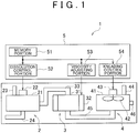
- a production apparatus 1 for an electric storage material includes a dissolution device 2, a viscosity adjusting device 3, a kneading device 4, a production control device 5 and the like.
- the dissolution device 2 is a device that dissolves a thickener in a solvent.
- the dissolution device 2 includes a housing 21, a microwave device 22 and a hopper 23, a supply pipe line 24 and the like.
- the housing 21 is formed in a hollow cylindrical shape.
- the microwave device 22 includes a magnetron, and is disposed on an upper surface of an upper portion of the housing 21.
- the hopper 23 that houses the thickener is provided to project from the upper surface of the housing 21 so that the thickener can be supplied into the housing 21.
- the supply pipe line 24 is connected to a lower surface of the housing 21 so that the solvent can be supplied into the housing 21.
- the viscosity adjusting device 3 is a device that adjusts the viscosity of the solution of the thickener.
- the viscosity adjusting device 3 includes a housing 31, an ultrasonic device 32, an introduction pipe line 33 and the like.
- the housing 31 is formed in a hollow cylindrical shape.
- the ultrasonic device 32 is disposed at an outer periphery of the housing 31.
- an ultrasonic wave generating element such as a piezoelectric element, is in close contact with, and is secured to an outer peripheral surface of the housing 31.
- the introduction pipe line 33 is disposed between a peripheral wall of the housing 21 of the dissolution device 2 and an upper surface of the housing 31 so that the solution of the thickener can be introduced from the housing 21 of the dissolution device 2 into the housing 31.
- the kneading device 4 is a device that kneads the solution of the thickener having the adjusted viscosity, and the active substance.
- the kneading device 4 includes a housing 41, agitating blades 42, a drive motor 43, a hopper 44, an introduction pipe line 45, a drainage pipe line 46 and the like.
- the housing 41 is formed in a hollow cylindrical shape.
- a rotary shaft for the agitating blades 42 is supported at a center portion of an upper surface of the housing 41 so that the agitating blades 42 are rotatable within the housing 41.
- the drive motor 43 is secured to an upper surface of an upper portion of the housing 41, and a motor shaft of the drive motor 43 is coupled to the rotary shaft for the agitating blades 42.
- the hopper 44 that houses the powder of the active substance or the like is provided to project from the upper surface of the housing 41 so that the powder of the active substance can be supplied into the housing 41.
- the introduction pipe line 45 is disposed between a lower surface of the housing 31 of the viscosity adjusting device 3 and a lower surface of the housing 41 so that the solution of the thickener can be supplied from the housing 31 of the viscosity adjusting device 3 into the housing 41.
- the drainage pipe line 46 is disposed at an outer peripheral surface of the housing 41 so that the slurry of the active material can be drained to the outside.
- the production control device 5 includes a memory portion 51, a dissolution control portion 52, a viscosity adjusting portion 53, a kneading control portion 54 and the like.
- the memory portion 51 stores data indicating a relationship between a viscosity of the solution of the thickener and an application time during which microwaves are applied (i.e., a thickener dissolution time) (refer to FIG. 3 ), data indicating a relationship between a viscosity of the slurry of the active material and a viscosity of the solution of the thickener (refer to FIG.
- the dissolution control portion 52 is a control portion that controls the operation of the dissolution device 2.
- the dissolution control portion 52 produces the solution of the thickener by operating the microwave device 22 so that the microwave device 22 generates microwaves, and the microwaves are applied to the solvent supplied into the housing 21, and thus, the thickener is dissolved in the solvent. That is, the dissolution control portion 52 controls the dissolution of the thickener by applying the microwaves for a predetermined time so that the solution of the thickener has a certain viscosity that is obtained at the time when the thickener is completely dissolved in the solvent.
- the viscosity adjusting portion 53 is a control portion that controls the operation of the viscosity adjusting device 3.
- the viscosity adjusting portion 53 adjusts the viscosity of the solution of the thickener by operating the ultrasonic device 32 so that the ultrasonic device 32 generates ultrasonic waves, and the ultrasonic waves are applied to the solution of the thickener supplied into the housing 31. That is, the viscosity adjusting portion 53 determines the viscosity of the solution of the thickener, based on the final viscosity of the slurry of the active material, and controls the viscosity adjustment by applying the ultrasonic waves for a predetermined time so that the solution of the thickener has the determined viscosity.
- the kneading control portion 54 is a control portion that controls the operation of the kneading device 4.
- the kneading control portion 54 produces the slurry of the active material by driving the drive motor 43 so as to rotate the agitating blades 42 for agitating the solution of the thickener, the active substance and the like, which are supplied into the housing 41.
- the kneading control portion 54 sets an index for kneading based on a kinetic energy of particles in the active material, a mean free path of the particles in the active material and a kneading time during which the active material are kneaded, as will be detailed later.
- the kneading control portion 54 sets a condition for kneading so that the set index for kneading becomes equal to or lower than a target value, and controls the kneading of the active material according to the set condition for kneading.
- the thickener, the solvent, the powder of active substance and the like are introduced together into the kneading device, and are then agitated.
- the dissolution of the thickener, the dispersion of the powder of the active substance and the like, and the viscosity adjustment for these materials are all performed in one kneading device.
- the active substance since the active substance is subjected to shearing force for a long time, the active substance may be damaged.
- the above-described processes are performed, respectively, in the dissolution device 2 that dissolves the thickener in the solvent, the viscosity adjusting device 3 that adjusts the viscosity of the solution of the thickener and the kneading device 4 that disperses and kneads the powder of the active substance and the like in the solution of the thickener having the adjusted viscosity. Accordingly, the time during which the active substance is subjected to the shearing force can be shortened, and thus, it is possible to suppress damage to the active substance. Thus, high battery performance can be obtained.
- step S1 the data relating to the dissolution of the thickener is read (step S1), and the thickener and the solvent are introduced into the dissolution device 2 (step S2). Further, the dissolution device 2 is operated (step S3), and it is determined whether a predetermined dissolution time has elapsed (step S4). If the predetermined dissolution time has elapsed, the operation of the dissolution device 2 is stopped (step S5).
- the dissolution control portion 52 reads data relating to the masses of the thickener and the solvent and data relating to the dissolution time, from the memory portion 51, and introduces a predetermined amount of the thickener into the housing 21 through the hopper 23, and introduces a predetermined amount of the solvent into the housing 21 through the supply pipe line 24. Further, the dissolution control portion 52 operates the microwave device 22 to apply microwaves to the solvent in the housing 21 for a predetermined dissolution time.
- the dissolution of the thickener in the solvent will be described.
- an initial viscosity of the solvent is ⁇ o
- the viscosity of the solution of the thickener at the time when the thickener is completely dissolved in the solvent after the thickener is introduced into the solvent becomes ⁇ s that is constant.
- the degree of solubility of the thickener with respect to the solvent can be determined by monitoring the viscosity of the solution of the thickener.
- the solvent is vibrated by microwaves so as to dissolve the thickener in the solvent.
- FIG. 3 it has been confirmed in experiments that the thickener can be efficiently dissolved in the solvent with the use of the microwaves, as compared to the dissolution of the thickener in the solvent by agitation or the dissolution of the thickener in the solvent by heating.
- the time T required for adjusting the viscosity of the solution of the thickener to ⁇ s which is a target value of the solution of the thickener, can be shortened to T11 ( ⁇ T12 ⁇ T13), while the time T is T12 in the case where agitating force is used, and the time T is T13 (> T12) in the case where heating is used.
- electric power required for dissolution with the use of the microwaves is lower than electric power required for dissolution with the use of the agitating force.
- the dissolution with the use of the microwaves is performed by applying the microwaves to the solvent so that the solvent is vibrated and the solvent penetrates into the thickener.
- the frequency band of the microwaves should be a frequency band in which the solvent can readily absorb the energy of the microwaves. Accordingly, in the case of using, for example, water as the solvent, a frequency band from 0.9 to 400 GHz is used. It is noted here that the microwaves described in this embodiment are microwaves that are generated by equipment such as a microwave oven.
- step S6 data relating to the viscosity adjustment are read (step S6), and the solution of the thickener is introduced into the viscosity adjusting device 3 (step S7). Further, the viscosity adjusting device 3 is operated (step S8), and it is determined whether a predetermined viscosity adjusting time has elapsed (step S9). If the predetermined viscosity adjusting time has elapsed, the operation of the viscosity adjusting device 3 is stopped (step S10). Specifically, the viscosity adjusting portion 53 introduces the solution of the thickener from the housing 21 of the dissolution device 2 into the housing 31 through the introduction pipe line 33. Then, the ultrasonic device 32 is operated so as to apply ultrasonic waves to the solution of the thickener in the housing 31 for the predetermined viscosity adjusting time.
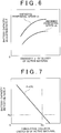
- a final viscosity v of the slurry of the active material is proportional to the viscosity ⁇ of the solution of the thickener.
- the viscosity v of the slurry of the active material can be adjusted into a predetermined range of va to vb that can be determined in view of the balance between the initial battery performance and the efficiency in performing the applying and drying steps.
- the viscosity ⁇ of the solution of the thickener is adjusted into a predetermined viscosity range of ⁇ a to ⁇ b as shown in FIG 4 , or is adjusted to a value ⁇ c that is higher than the upper limit value ⁇ b of the above-described predetermined range, by a predetermined value.
- the viscosity ⁇ of the solution of the thickener becomes the value ⁇ c that is higher than the upper limit value ⁇ b by the predetermined value, the viscosity ⁇ can be easily readjusted into the predetermined viscosity range of ⁇ a to ⁇ b, by adding the solvent afterward.
- the adjustment of the viscosity of the solution of the thickener may be performed by cutting the molecular chains of the thickener with the use of shear energy obtained by the agitating force as in the conventional case.
- the adjustment is performed by cutting the molecular chains of the thickener with the use of collision energy and shear energy that are obtained by the ultrasonic waves.
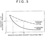
- the adjustment of the viscosity of the solution of the thickener with the use of the ultrasonic waves is efficient, as compared to the adjustment of the viscosity of the solution of the thickener with the use of the agitating force.
- the time T required for adjusting the viscosity ⁇ of the solution of the thickener to a viscosity ⁇ p that is a target value can be shortened to T1 ( ⁇ T2) in the case where the ultrasonic waves are used, while the time T is the time T2 in the case where the agitating force is used.
- electric power required for the viscosity adjustment with the use of the ultrasonic waves is lower than electric power required for the viscosity adjustment with the use of the agitating force.
- the viscosity ⁇ of the solution of the thickener is lowered as the viscosity adjusting time T elapses, and finally becomes the viscosity of water.
- step S11 data relating to the kneading of the solution of the thickener, the powder of the active substance and the like are read (steps S11), and the solution of the thickener, the powder of the active substance and the like are introduced into the kneading device 4 (step S12). Further, the kneading device 4 is operated (step S13), and it is determined whether a predetermined kneading time has elapsed (step S14). If the predetermined kneading time has elapsed, the operation of the kneading device 4 is stopped (step S15), and the final slurry of the active material is produced.
- the kneading control portion 54 reads data relating to masses of the solution of the thickener, the powder of the active substance and the like, and data relating to the kneading time, introduces a predetermined amount of the powder of the active substance and the like into the housing 41 through the hopper 44, and also introduces a predetermined amount of the solution of the thickener into the housing 41 through the introduction pipe line 45. Further, the drive motor 43 is driven to rotate the agitating blades 42 for a predetermined kneading time.
- the capacity retention rate P of the battery that is, the durability of the battery (repeated charge and discharge characteristic) is increased as the viscosity v of the slurry of the active material is increased.
- the capacity retention rate P of the battery is lowered even if the kneading is performed so as to obtain the same viscosity v of the slurry of the active material.
- the capacity retention rate P of the battery is adversely influenced by the damage to the particles of the active material.
- the frequency of collision between the particles of the active material is determined based on a known mean free path with the use of a model in which the particles of the active material perform free motion in a predetermined space.
- a cumulative collision energy D of the particles of the active material which is the index for kneading
- a cumulative collision energy D of the particles of the active material can be determined by multiplying the kinetic energy mv 2 /2 of the particles of the active material, by the collision frequency ⁇ 2 ⁇ v of the particles of the active material and the kneading time t for the active material.
- the damaged state of the particles of the active material which are damaged by kneading, can be estimated even before the kneading step.
- D mv 2 2 ⁇ 2 ⁇ v ⁇ t
- D the cumulative collision energy of the particles of the active material
- m a weight of a single particle among the particles of the active material
- v the kneading peripheral speed of the agitating blades 42
- ⁇ the solid content rate of the active material
- ⁇ is a mean particle diameter of the particles of the active material
- t is the kneading time for the active material.
- a relationship between the capacity retention rate P of the battery and the cumulative collision energy D of the active material is obtained.
- This relationship is obtained by adjusting the kneading peripheral speed v of the agitating blades 42, the solid content rate ⁇ of the active material (as to the solid content rate, the ratio between the solid content and the liquid content is changed), and the kneading time t for the active material.
- the kneading peripheral speed v, the solid content rate ⁇ , and the kneading time t are factors responsible for damage to the particles of the active material.
- a relational expression P f(D) is obtained, and then, a cumulative collision energy Dp of the active material, which corresponds to a minimum required capacity retention rate Pp of the battery, is determined.
- a kneading condition in which the cumulative collision energy of the active material becomes equal to or lower than Dp is set. In other words, the kneading peripheral speed v of the agitating blades 42, the solid content rate ⁇ of the active material and the kneading time t for the active material are set.
- the frequency of collision between the particles of the active material is determined based on the mean free path of the particles of the active material with the use of the model in which the particles of the active material perform free motion in the predetermined space.
- the cumulative collision energy of the active material can be determined by multiplying the frequency of collision between the particles of the active material, by the kinetic energy of the active material and the kneading time for the active material, and can be used as the index for the durability of the battery.
- the damaged state of the particles of the active material during kneading can be estimated even before the kneading step. Accordingly, the kneading can be performed in a manner such that the particles of the active material are hardly damaged. Thus, it is possible to produce a battery with high durability.
- the production apparatus 1 for an electric storage material which includes the dissolution device 2 having the microwave device 22 and the viscosity adjusting device 3 having the ultrasonic device 32, has been described.
- the production apparatus for an electric storage material may include a viscosity adjusting device having agitating blades, instead of the viscosity adjusting device 3.
- the production apparatus for an electric storage material may include a single device that performs both the dissolution and the viscosity adjustment.
- the kneading device 4 including the agitating blades 42 has been described. Instead, a kneading device including a screw may be used.
- the present invention may be also applied for producing an active material for a positive electrode in a lithium ion secondary battery.
- the microwaves are applied when a binder such as polyvinylidene fluoride is dissolved in a solvent such as N-methylpyrrolidone, but the ultrasonic waves are not applied when a conductive agent such as acetylene black is mixed into the solution. This is because the viscosity of the solution can be adjusted by changing the amount of the mixed conductive agent such as acetylene black.
- the electric storage material, to which the present invention is applied should not be limited to the active material for an electrode in a lithium ion secondary battery.
- the present invention may be applied to other electric storage materials, for example, a material for a capacitor.
Landscapes
- Chemical & Material Sciences (AREA)
- Engineering & Computer Science (AREA)
- Chemical Kinetics & Catalysis (AREA)
- Electrochemistry (AREA)
- General Chemical & Material Sciences (AREA)
- Manufacturing & Machinery (AREA)
- Materials Engineering (AREA)
- Health & Medical Sciences (AREA)
- Toxicology (AREA)
- Organic Chemistry (AREA)
- General Health & Medical Sciences (AREA)
- Battery Electrode And Active Subsutance (AREA)
- Electric Double-Layer Capacitors Or The Like (AREA)
- Fixed Capacitors And Capacitor Manufacturing Machines (AREA)
Applications Claiming Priority (2)
| Application Number | Priority Date | Filing Date | Title |
|---|---|---|---|
| JP2013024366 | 2013-02-12 | ||
| JP2013236709A JP6354135B2 (ja) | 2013-02-12 | 2013-11-15 | 蓄電材料の製造装置および製造方法 |
Publications (2)
| Publication Number | Publication Date |
|---|---|
| EP2765633A1 EP2765633A1 (en) | 2014-08-13 |
| EP2765633B1 true EP2765633B1 (en) | 2020-12-23 |
Family
ID=50033416
Family Applications (1)
| Application Number | Title | Priority Date | Filing Date |
|---|---|---|---|
| EP14154089.8A Not-in-force EP2765633B1 (en) | 2013-02-12 | 2014-02-06 | Production method for electric storage material |
Country Status (4)
| Country | Link |
|---|---|
| US (1) | US9531007B2 (enExample) |
| EP (1) | EP2765633B1 (enExample) |
| JP (1) | JP6354135B2 (enExample) |
| CN (1) | CN103985844B (enExample) |
Families Citing this family (9)
| Publication number | Priority date | Publication date | Assignee | Title |
|---|---|---|---|---|
| JP6119547B2 (ja) * | 2013-10-09 | 2017-04-26 | 株式会社豊田自動織機 | 電極用スラリーの製造装置 |
| JP6321404B2 (ja) | 2014-02-26 | 2018-05-09 | 株式会社ジェイテクト | 蓄電材料の製造装置および製造方法 |
| JP6291903B2 (ja) | 2014-02-26 | 2018-03-14 | 株式会社ジェイテクト | 混練装置 |
| JP6375711B2 (ja) | 2014-06-13 | 2018-08-22 | 株式会社ジェイテクト | 蓄電材料の製造装置及び製造方法 |
| JP6442943B2 (ja) * | 2014-09-12 | 2018-12-26 | 株式会社ジェイテクト | 蓄電材料の製造装置及び製造方法 |
| EP3335299A4 (en) | 2015-08-11 | 2019-06-12 | Genesis Robotics and Motion Technologies Canada, ULC | ELECTRICAL MACHINE |
| US11139707B2 (en) | 2015-08-11 | 2021-10-05 | Genesis Robotics And Motion Technologies Canada, Ulc | Axial gap electric machine with permanent magnets arranged between posts |
| US20180277313A1 (en) * | 2015-09-30 | 2018-09-27 | Osaka Soda Co., Ltd. | Gel electrolyte composition |
| US11043885B2 (en) | 2016-07-15 | 2021-06-22 | Genesis Robotics And Motion Technologies Canada, Ulc | Rotary actuator |
Family Cites Families (28)
| Publication number | Priority date | Publication date | Assignee | Title |
|---|---|---|---|---|
| GB818489A (en) | 1957-01-16 | 1959-08-19 | Columbium Carbon Company | Improvements in process and apparatus for effecting particulate dispersions |
| US5707763A (en) | 1994-10-19 | 1998-01-13 | Daikin Industries, Ltd. | Binder for batteries, and electrode compositions and batteries incorporating same |
| EP0789412B1 (en) | 1994-10-27 | 2000-01-19 | Fuji Photo Film Co., Ltd. | Nonaqueous secondary cell and its manufacturing method |
| JPH08190912A (ja) | 1995-01-12 | 1996-07-23 | Fuji Photo Film Co Ltd | 非水二次電池の負極用合剤の製造方法 |
| JP2000306598A (ja) * | 1999-04-19 | 2000-11-02 | Toshiba Battery Co Ltd | アルカリ二次電池用正極の製造方法、その正極が組み込まれているアルカリ二次電池 |
| US6562936B1 (en) * | 1999-07-06 | 2003-05-13 | Teijin Limited | Apparatus and method for producing resin |
| JP4941692B2 (ja) | 2000-05-16 | 2012-05-30 | 株式会社豊田中央研究所 | リチウム二次電池正極活物質用リチウムマンガン複合酸化物およびその製造方法 |
| AU2003256799A1 (en) | 2002-07-25 | 2004-02-16 | University Of Florida | Flexible screw feeder/mixer for precision dosing and feeding of particulate systems |
| JP2005276502A (ja) | 2004-03-23 | 2005-10-06 | Mitsubishi Chemicals Corp | リチウム二次電池正極活物質用リチウム遷移金属複合酸化物粉体及びその製造方法、その前駆体及びその製造方法、それを用いたリチウム二次電池正極、並びにリチウム二次電池 |
| CN100508251C (zh) * | 2005-02-02 | 2009-07-01 | 深圳市比克电池有限公司 | 一种锂离子电池正极片制造方法、正极片和锂离子电池 |
| JP2006310120A (ja) | 2005-04-28 | 2006-11-09 | Matsushita Electric Ind Co Ltd | リチウムイオン二次電池用極板のペースト製造方法 |
| UA83075C2 (uk) | 2006-04-27 | 2008-06-10 | Елена Моисеевна Шембель | Електрод для первинних, вторинних літієвих джерел струму та суперконденсаторів і спосіб його виготовлення |
| JP4104645B2 (ja) | 2006-06-27 | 2008-06-18 | 花王株式会社 | リチウム電池正極用複合材料の製造方法 |
| KR101153532B1 (ko) | 2006-06-27 | 2012-06-11 | 가오 가부시키가이샤 | 리튬 전지 양극용 복합재료의 제조방법 |
| US20080212261A1 (en) * | 2006-07-05 | 2008-09-04 | Rensselaer Polytechnic Institute | Energy storage devices and composite articles associated with the same |
| JP2008047512A (ja) | 2006-07-18 | 2008-02-28 | Nissan Motor Co Ltd | 非水電解質二次電池用正極 |
| US20090279230A1 (en) | 2008-05-08 | 2009-11-12 | Renewable Energy Development, Inc. | Electrode structure for the manufacture of an electric double layer capacitor |
| FR2941875B1 (fr) | 2009-02-11 | 2011-09-23 | Commissariat Energie Atomique | Procede de preparation d'un melange d'une poudre d'un compose actif d'electrode et d'une poudre d'un compose conducteur electronique, melange ainsi obtenu, electrode, cellule et accumulateur |
| JP5621772B2 (ja) | 2009-06-30 | 2014-11-12 | 日本ゼオン株式会社 | 二次電池用電極及び二次電池 |
| JP5879673B2 (ja) | 2009-09-03 | 2016-03-08 | ソニー株式会社 | 非水電解質二次電池用負極の製造方法 |
| CN101931074B (zh) * | 2009-12-15 | 2012-09-05 | 辽宁弘光科技集团有限公司 | 一种锂电池电极的涂膜基料组成物及锂电池 |
| JP5408018B2 (ja) | 2010-04-16 | 2014-02-05 | 住友金属鉱山株式会社 | 非水系電解質二次電池用正極活物質とその製造方法、および、これを用いた非水系電解質二次電池 |
| CN103155233B (zh) * | 2010-10-05 | 2015-05-13 | 丰田自动车株式会社 | 电池的制造方法 |
| CN102593518A (zh) * | 2011-01-13 | 2012-07-18 | 苏州能斯特新能源有限公司 | 一种锂离子电池的制备方法 |
| DE102011077130A1 (de) | 2011-06-07 | 2012-12-13 | Siemens Ag | Mischvorrichtung |
| KR102015376B1 (ko) | 2012-02-27 | 2019-08-28 | 제온 코포레이션 | 2 차 전지 부극용 바인더 조성물, 2 차 전지용 부극, 2 차 전지 부극용 슬러리 조성물, 제조 방법 및 2 차 전지 |
| CA2776205A1 (en) | 2012-05-08 | 2013-11-08 | Hydro-Quebec | Lithium-ion secondary battery and method of producing same |
| WO2014016921A1 (ja) | 2012-07-25 | 2014-01-30 | トヨタ自動車株式会社 | 二軸押出混練機、およびそれを用いた電極の製造方法 |
-
2013
- 2013-11-15 JP JP2013236709A patent/JP6354135B2/ja not_active Expired - Fee Related
-
2014
- 2014-02-04 US US14/172,299 patent/US9531007B2/en not_active Expired - Fee Related
- 2014-02-06 EP EP14154089.8A patent/EP2765633B1/en not_active Not-in-force
- 2014-02-10 CN CN201410046316.4A patent/CN103985844B/zh not_active Expired - Fee Related
Non-Patent Citations (1)
| Title |
|---|
| LEE G W ET AL: "Effect of slurry preparation process on electrochemical performances of LiCoO"2 composite electrode", JOURNAL OF POWER SOURCES, ELSEVIER SA, CH, vol. 195, no. 18, 15 September 2010 (2010-09-15), pages 6049 - 6054, XP027148141, ISSN: 0378-7753, [retrieved on 20100114] * |
Also Published As
| Publication number | Publication date |
|---|---|
| US9531007B2 (en) | 2016-12-27 |
| CN103985844B (zh) | 2018-10-26 |
| JP6354135B2 (ja) | 2018-07-11 |
| US20140225043A1 (en) | 2014-08-14 |
| CN103985844A (zh) | 2014-08-13 |
| JP2014179313A (ja) | 2014-09-25 |
| EP2765633A1 (en) | 2014-08-13 |
Similar Documents
| Publication | Publication Date | Title |
|---|---|---|
| EP2765633B1 (en) | Production method for electric storage material | |
| EP2913102B1 (en) | Kneading process | |
| WO2017031884A1 (zh) | 一种锂电池正极浆料的制备方法 | |
| US10637057B2 (en) | Method for manufacturing slurry for positive electrode of nonaqueous electrolyte secondary battery and apparatus therefor | |
| JP4297533B2 (ja) | リチウムイオン電池材料の製造方法 | |
| US9825298B2 (en) | Apparatus and method for manufacturing an electricity storage material | |
| EP2913869B1 (en) | Apparatus and process for producing electricity storage material | |
| US10076855B2 (en) | Apparatus and method for manufacturing an electricity storage material | |
| CN105428608B (zh) | 蓄电材料的制造装置以及制造方法 | |
| JP6248565B2 (ja) | 蓄電材料の製造装置および製造方法 | |
| JP2012133931A (ja) | 正極電極スラリーの製造方法、および正極電極スラリーの製造装置 | |
| Arslan et al. | Current and future trends in lithium-ion battery electrode production machinery: A comprehensive review | |
| CN118448575A (zh) | 非水二次电池用正极的制造方法及制造装置 | |
| KR20140087632A (ko) | 초음파를 이용한 슬러리 제조 장치 |
Legal Events
| Date | Code | Title | Description |
|---|---|---|---|
| PUAI | Public reference made under article 153(3) epc to a published international application that has entered the european phase |
Free format text: ORIGINAL CODE: 0009012 |
|
| 17P | Request for examination filed |
Effective date: 20140206 |
|
| AK | Designated contracting states |
Kind code of ref document: A1 Designated state(s): AL AT BE BG CH CY CZ DE DK EE ES FI FR GB GR HR HU IE IS IT LI LT LU LV MC MK MT NL NO PL PT RO RS SE SI SK SM TR |
|
| AX | Request for extension of the european patent |
Extension state: BA ME |
|
| R17P | Request for examination filed (corrected) |
Effective date: 20140904 |
|
| 17Q | First examination report despatched |
Effective date: 20161004 |
|
| STAA | Information on the status of an ep patent application or granted ep patent |
Free format text: STATUS: EXAMINATION IS IN PROGRESS |
|
| GRAP | Despatch of communication of intention to grant a patent |
Free format text: ORIGINAL CODE: EPIDOSNIGR1 |
|
| STAA | Information on the status of an ep patent application or granted ep patent |
Free format text: STATUS: GRANT OF PATENT IS INTENDED |
|
| INTG | Intention to grant announced |
Effective date: 20200806 |
|
| GRAS | Grant fee paid |
Free format text: ORIGINAL CODE: EPIDOSNIGR3 |
|
| GRAA | (expected) grant |
Free format text: ORIGINAL CODE: 0009210 |
|
| STAA | Information on the status of an ep patent application or granted ep patent |
Free format text: STATUS: THE PATENT HAS BEEN GRANTED |
|
| AK | Designated contracting states |
Kind code of ref document: B1 Designated state(s): AL AT BE BG CH CY CZ DE DK EE ES FI FR GB GR HR HU IE IS IT LI LT LU LV MC MK MT NL NO PL PT RO RS SE SI SK SM TR |
|
| REG | Reference to a national code |
Ref country code: GB Ref legal event code: FG4D |
|
| REG | Reference to a national code |
Ref country code: DE Ref legal event code: R096 Ref document number: 602014073515 Country of ref document: DE |
|
| REG | Reference to a national code |
Ref country code: AT Ref legal event code: REF Ref document number: 1348590 Country of ref document: AT Kind code of ref document: T Effective date: 20210115 |
|
| REG | Reference to a national code |
Ref country code: IE Ref legal event code: FG4D |
|
| PG25 | Lapsed in a contracting state [announced via postgrant information from national office to epo] |
Ref country code: FI Free format text: LAPSE BECAUSE OF FAILURE TO SUBMIT A TRANSLATION OF THE DESCRIPTION OR TO PAY THE FEE WITHIN THE PRESCRIBED TIME-LIMIT Effective date: 20201223 Ref country code: RS Free format text: LAPSE BECAUSE OF FAILURE TO SUBMIT A TRANSLATION OF THE DESCRIPTION OR TO PAY THE FEE WITHIN THE PRESCRIBED TIME-LIMIT Effective date: 20201223 Ref country code: NO Free format text: LAPSE BECAUSE OF FAILURE TO SUBMIT A TRANSLATION OF THE DESCRIPTION OR TO PAY THE FEE WITHIN THE PRESCRIBED TIME-LIMIT Effective date: 20210323 Ref country code: GR Free format text: LAPSE BECAUSE OF FAILURE TO SUBMIT A TRANSLATION OF THE DESCRIPTION OR TO PAY THE FEE WITHIN THE PRESCRIBED TIME-LIMIT Effective date: 20210324 |
|
| REG | Reference to a national code |
Ref country code: AT Ref legal event code: MK05 Ref document number: 1348590 Country of ref document: AT Kind code of ref document: T Effective date: 20201223 |
|
| REG | Reference to a national code |
Ref country code: NL Ref legal event code: MP Effective date: 20201223 |
|
| PG25 | Lapsed in a contracting state [announced via postgrant information from national office to epo] |
Ref country code: BG Free format text: LAPSE BECAUSE OF FAILURE TO SUBMIT A TRANSLATION OF THE DESCRIPTION OR TO PAY THE FEE WITHIN THE PRESCRIBED TIME-LIMIT Effective date: 20210323 Ref country code: SE Free format text: LAPSE BECAUSE OF FAILURE TO SUBMIT A TRANSLATION OF THE DESCRIPTION OR TO PAY THE FEE WITHIN THE PRESCRIBED TIME-LIMIT Effective date: 20201223 Ref country code: LV Free format text: LAPSE BECAUSE OF FAILURE TO SUBMIT A TRANSLATION OF THE DESCRIPTION OR TO PAY THE FEE WITHIN THE PRESCRIBED TIME-LIMIT Effective date: 20201223 |
|
| PG25 | Lapsed in a contracting state [announced via postgrant information from national office to epo] |
Ref country code: HR Free format text: LAPSE BECAUSE OF FAILURE TO SUBMIT A TRANSLATION OF THE DESCRIPTION OR TO PAY THE FEE WITHIN THE PRESCRIBED TIME-LIMIT Effective date: 20201223 Ref country code: NL Free format text: LAPSE BECAUSE OF FAILURE TO SUBMIT A TRANSLATION OF THE DESCRIPTION OR TO PAY THE FEE WITHIN THE PRESCRIBED TIME-LIMIT Effective date: 20201223 |
|
| REG | Reference to a national code |
Ref country code: LT Ref legal event code: MG9D |
|
| PG25 | Lapsed in a contracting state [announced via postgrant information from national office to epo] |
Ref country code: SK Free format text: LAPSE BECAUSE OF FAILURE TO SUBMIT A TRANSLATION OF THE DESCRIPTION OR TO PAY THE FEE WITHIN THE PRESCRIBED TIME-LIMIT Effective date: 20201223 Ref country code: RO Free format text: LAPSE BECAUSE OF FAILURE TO SUBMIT A TRANSLATION OF THE DESCRIPTION OR TO PAY THE FEE WITHIN THE PRESCRIBED TIME-LIMIT Effective date: 20201223 Ref country code: PT Free format text: LAPSE BECAUSE OF FAILURE TO SUBMIT A TRANSLATION OF THE DESCRIPTION OR TO PAY THE FEE WITHIN THE PRESCRIBED TIME-LIMIT Effective date: 20210423 Ref country code: LT Free format text: LAPSE BECAUSE OF FAILURE TO SUBMIT A TRANSLATION OF THE DESCRIPTION OR TO PAY THE FEE WITHIN THE PRESCRIBED TIME-LIMIT Effective date: 20201223 Ref country code: SM Free format text: LAPSE BECAUSE OF FAILURE TO SUBMIT A TRANSLATION OF THE DESCRIPTION OR TO PAY THE FEE WITHIN THE PRESCRIBED TIME-LIMIT Effective date: 20201223 Ref country code: CZ Free format text: LAPSE BECAUSE OF FAILURE TO SUBMIT A TRANSLATION OF THE DESCRIPTION OR TO PAY THE FEE WITHIN THE PRESCRIBED TIME-LIMIT Effective date: 20201223 Ref country code: EE Free format text: LAPSE BECAUSE OF FAILURE TO SUBMIT A TRANSLATION OF THE DESCRIPTION OR TO PAY THE FEE WITHIN THE PRESCRIBED TIME-LIMIT Effective date: 20201223 |
|
| PG25 | Lapsed in a contracting state [announced via postgrant information from national office to epo] |
Ref country code: PL Free format text: LAPSE BECAUSE OF FAILURE TO SUBMIT A TRANSLATION OF THE DESCRIPTION OR TO PAY THE FEE WITHIN THE PRESCRIBED TIME-LIMIT Effective date: 20201223 Ref country code: AT Free format text: LAPSE BECAUSE OF FAILURE TO SUBMIT A TRANSLATION OF THE DESCRIPTION OR TO PAY THE FEE WITHIN THE PRESCRIBED TIME-LIMIT Effective date: 20201223 |
|
| REG | Reference to a national code |
Ref country code: DE Ref legal event code: R119 Ref document number: 602014073515 Country of ref document: DE |
|
| PG25 | Lapsed in a contracting state [announced via postgrant information from national office to epo] |
Ref country code: IS Free format text: LAPSE BECAUSE OF FAILURE TO SUBMIT A TRANSLATION OF THE DESCRIPTION OR TO PAY THE FEE WITHIN THE PRESCRIBED TIME-LIMIT Effective date: 20210423 Ref country code: MC Free format text: LAPSE BECAUSE OF FAILURE TO SUBMIT A TRANSLATION OF THE DESCRIPTION OR TO PAY THE FEE WITHIN THE PRESCRIBED TIME-LIMIT Effective date: 20201223 |
|
| REG | Reference to a national code |
Ref country code: BE Ref legal event code: MM Effective date: 20210228 |
|
| PG25 | Lapsed in a contracting state [announced via postgrant information from national office to epo] |
Ref country code: CH Free format text: LAPSE BECAUSE OF NON-PAYMENT OF DUE FEES Effective date: 20210228 Ref country code: AL Free format text: LAPSE BECAUSE OF FAILURE TO SUBMIT A TRANSLATION OF THE DESCRIPTION OR TO PAY THE FEE WITHIN THE PRESCRIBED TIME-LIMIT Effective date: 20201223 Ref country code: LU Free format text: LAPSE BECAUSE OF NON-PAYMENT OF DUE FEES Effective date: 20210206 Ref country code: LI Free format text: LAPSE BECAUSE OF NON-PAYMENT OF DUE FEES Effective date: 20210228 Ref country code: IT Free format text: LAPSE BECAUSE OF FAILURE TO SUBMIT A TRANSLATION OF THE DESCRIPTION OR TO PAY THE FEE WITHIN THE PRESCRIBED TIME-LIMIT Effective date: 20201223 |
|
| PLBE | No opposition filed within time limit |
Free format text: ORIGINAL CODE: 0009261 |
|
| STAA | Information on the status of an ep patent application or granted ep patent |
Free format text: STATUS: NO OPPOSITION FILED WITHIN TIME LIMIT |
|
| GBPC | Gb: european patent ceased through non-payment of renewal fee |
Effective date: 20210323 |
|
| PG25 | Lapsed in a contracting state [announced via postgrant information from national office to epo] |
Ref country code: DK Free format text: LAPSE BECAUSE OF FAILURE TO SUBMIT A TRANSLATION OF THE DESCRIPTION OR TO PAY THE FEE WITHIN THE PRESCRIBED TIME-LIMIT Effective date: 20201223 Ref country code: ES Free format text: LAPSE BECAUSE OF FAILURE TO SUBMIT A TRANSLATION OF THE DESCRIPTION OR TO PAY THE FEE WITHIN THE PRESCRIBED TIME-LIMIT Effective date: 20201223 |
|
| 26N | No opposition filed |
Effective date: 20210924 |
|
| PG25 | Lapsed in a contracting state [announced via postgrant information from national office to epo] |
Ref country code: DE Free format text: LAPSE BECAUSE OF NON-PAYMENT OF DUE FEES Effective date: 20210901 Ref country code: GB Free format text: LAPSE BECAUSE OF NON-PAYMENT OF DUE FEES Effective date: 20210323 Ref country code: FR Free format text: LAPSE BECAUSE OF NON-PAYMENT OF DUE FEES Effective date: 20210223 Ref country code: IE Free format text: LAPSE BECAUSE OF NON-PAYMENT OF DUE FEES Effective date: 20210206 |
|
| PG25 | Lapsed in a contracting state [announced via postgrant information from national office to epo] |
Ref country code: SI Free format text: LAPSE BECAUSE OF FAILURE TO SUBMIT A TRANSLATION OF THE DESCRIPTION OR TO PAY THE FEE WITHIN THE PRESCRIBED TIME-LIMIT Effective date: 20201223 |
|
| PG25 | Lapsed in a contracting state [announced via postgrant information from national office to epo] |
Ref country code: IS Free format text: LAPSE BECAUSE OF FAILURE TO SUBMIT A TRANSLATION OF THE DESCRIPTION OR TO PAY THE FEE WITHIN THE PRESCRIBED TIME-LIMIT Effective date: 20210423 |
|
| PG25 | Lapsed in a contracting state [announced via postgrant information from national office to epo] |
Ref country code: BE Free format text: LAPSE BECAUSE OF NON-PAYMENT OF DUE FEES Effective date: 20210228 |
|
| PG25 | Lapsed in a contracting state [announced via postgrant information from national office to epo] |
Ref country code: HU Free format text: LAPSE BECAUSE OF FAILURE TO SUBMIT A TRANSLATION OF THE DESCRIPTION OR TO PAY THE FEE WITHIN THE PRESCRIBED TIME-LIMIT; INVALID AB INITIO Effective date: 20140206 |
|
| PG25 | Lapsed in a contracting state [announced via postgrant information from national office to epo] |
Ref country code: CY Free format text: LAPSE BECAUSE OF FAILURE TO SUBMIT A TRANSLATION OF THE DESCRIPTION OR TO PAY THE FEE WITHIN THE PRESCRIBED TIME-LIMIT Effective date: 20201223 |
|
| PG25 | Lapsed in a contracting state [announced via postgrant information from national office to epo] |
Ref country code: MK Free format text: LAPSE BECAUSE OF FAILURE TO SUBMIT A TRANSLATION OF THE DESCRIPTION OR TO PAY THE FEE WITHIN THE PRESCRIBED TIME-LIMIT Effective date: 20201223 |
|
| PG25 | Lapsed in a contracting state [announced via postgrant information from national office to epo] |
Ref country code: TR Free format text: LAPSE BECAUSE OF FAILURE TO SUBMIT A TRANSLATION OF THE DESCRIPTION OR TO PAY THE FEE WITHIN THE PRESCRIBED TIME-LIMIT Effective date: 20201223 |
|
| PG25 | Lapsed in a contracting state [announced via postgrant information from national office to epo] |
Ref country code: MT Free format text: LAPSE BECAUSE OF FAILURE TO SUBMIT A TRANSLATION OF THE DESCRIPTION OR TO PAY THE FEE WITHIN THE PRESCRIBED TIME-LIMIT Effective date: 20201223 |