EP2763606B1 - System for treating ischemic stroke - Google Patents
System for treating ischemic stroke Download PDFInfo
- Publication number
- EP2763606B1 EP2763606B1 EP12838884.0A EP12838884A EP2763606B1 EP 2763606 B1 EP2763606 B1 EP 2763606B1 EP 12838884 A EP12838884 A EP 12838884A EP 2763606 B1 EP2763606 B1 EP 2763606B1
- Authority
- EP
- European Patent Office
- Prior art keywords
- separator
- thromboembolic
- apexes
- struts
- rib
- Prior art date
- Legal status (The legal status is an assumption and is not a legal conclusion. Google has not performed a legal analysis and makes no representation as to the accuracy of the status listed.)
- Active
Links
Images


Classifications
-
- A—HUMAN NECESSITIES
- A61—MEDICAL OR VETERINARY SCIENCE; HYGIENE
- A61B—DIAGNOSIS; SURGERY; IDENTIFICATION
- A61B17/00—Surgical instruments, devices or methods
- A61B17/22—Implements for squeezing-off ulcers or the like on inner organs of the body; Implements for scraping-out cavities of body organs, e.g. bones; for invasive removal or destruction of calculus using mechanical vibrations; for removing obstructions in blood vessels, not otherwise provided for
- A61B17/221—Gripping devices in the form of loops or baskets for gripping calculi or similar types of obstructions
-
- A—HUMAN NECESSITIES
- A61—MEDICAL OR VETERINARY SCIENCE; HYGIENE
- A61B—DIAGNOSIS; SURGERY; IDENTIFICATION
- A61B17/00—Surgical instruments, devices or methods
- A61B17/22—Implements for squeezing-off ulcers or the like on inner organs of the body; Implements for scraping-out cavities of body organs, e.g. bones; for invasive removal or destruction of calculus using mechanical vibrations; for removing obstructions in blood vessels, not otherwise provided for
-
- A—HUMAN NECESSITIES
- A61—MEDICAL OR VETERINARY SCIENCE; HYGIENE
- A61B—DIAGNOSIS; SURGERY; IDENTIFICATION
- A61B17/00—Surgical instruments, devices or methods
- A61B2017/00526—Methods of manufacturing
-
- A—HUMAN NECESSITIES
- A61—MEDICAL OR VETERINARY SCIENCE; HYGIENE
- A61B—DIAGNOSIS; SURGERY; IDENTIFICATION
- A61B17/00—Surgical instruments, devices or methods
- A61B17/22—Implements for squeezing-off ulcers or the like on inner organs of the body; Implements for scraping-out cavities of body organs, e.g. bones; for invasive removal or destruction of calculus using mechanical vibrations; for removing obstructions in blood vessels, not otherwise provided for
- A61B17/22031—Gripping instruments, e.g. forceps, for removing or smashing calculi
- A61B2017/22034—Gripping instruments, e.g. forceps, for removing or smashing calculi for gripping the obstruction or the tissue part from inside
-
- A—HUMAN NECESSITIES
- A61—MEDICAL OR VETERINARY SCIENCE; HYGIENE
- A61B—DIAGNOSIS; SURGERY; IDENTIFICATION
- A61B17/00—Surgical instruments, devices or methods
- A61B17/22—Implements for squeezing-off ulcers or the like on inner organs of the body; Implements for scraping-out cavities of body organs, e.g. bones; for invasive removal or destruction of calculus using mechanical vibrations; for removing obstructions in blood vessels, not otherwise provided for
- A61B2017/22038—Implements for squeezing-off ulcers or the like on inner organs of the body; Implements for scraping-out cavities of body organs, e.g. bones; for invasive removal or destruction of calculus using mechanical vibrations; for removing obstructions in blood vessels, not otherwise provided for with a guide wire
- A61B2017/22042—Details of the tip of the guide wire
- A61B2017/22044—Details of the tip of the guide wire with a pointed tip
-
- A—HUMAN NECESSITIES
- A61—MEDICAL OR VETERINARY SCIENCE; HYGIENE
- A61B—DIAGNOSIS; SURGERY; IDENTIFICATION
- A61B17/00—Surgical instruments, devices or methods
- A61B17/22—Implements for squeezing-off ulcers or the like on inner organs of the body; Implements for scraping-out cavities of body organs, e.g. bones; for invasive removal or destruction of calculus using mechanical vibrations; for removing obstructions in blood vessels, not otherwise provided for
- A61B17/221—Gripping devices in the form of loops or baskets for gripping calculi or similar types of obstructions
- A61B2017/2215—Gripping devices in the form of loops or baskets for gripping calculi or similar types of obstructions having an open distal end
-
- A—HUMAN NECESSITIES
- A61—MEDICAL OR VETERINARY SCIENCE; HYGIENE
- A61B—DIAGNOSIS; SURGERY; IDENTIFICATION
- A61B2217/00—General characteristics of surgical instruments
- A61B2217/002—Auxiliary appliance
- A61B2217/005—Auxiliary appliance with suction drainage system
-
- A—HUMAN NECESSITIES
- A61—MEDICAL OR VETERINARY SCIENCE; HYGIENE
- A61F—FILTERS IMPLANTABLE INTO BLOOD VESSELS; PROSTHESES; DEVICES PROVIDING PATENCY TO, OR PREVENTING COLLAPSING OF, TUBULAR STRUCTURES OF THE BODY, e.g. STENTS; ORTHOPAEDIC, NURSING OR CONTRACEPTIVE DEVICES; FOMENTATION; TREATMENT OR PROTECTION OF EYES OR EARS; BANDAGES, DRESSINGS OR ABSORBENT PADS; FIRST-AID KITS
- A61F2/00—Filters implantable into blood vessels; Prostheses, i.e. artificial substitutes or replacements for parts of the body; Appliances for connecting them with the body; Devices providing patency to, or preventing collapsing of, tubular structures of the body, e.g. stents
- A61F2/01—Filters implantable into blood vessels
- A61F2/013—Distal protection devices, i.e. devices placed distally in combination with another endovascular procedure, e.g. angioplasty or stenting
-
- A—HUMAN NECESSITIES
- A61—MEDICAL OR VETERINARY SCIENCE; HYGIENE
- A61M—DEVICES FOR INTRODUCING MEDIA INTO, OR ONTO, THE BODY; DEVICES FOR TRANSDUCING BODY MEDIA OR FOR TAKING MEDIA FROM THE BODY; DEVICES FOR PRODUCING OR ENDING SLEEP OR STUPOR
- A61M25/00—Catheters; Hollow probes
- A61M25/10—Balloon catheters
- A61M2025/1043—Balloon catheters with special features or adapted for special applications
- A61M2025/1052—Balloon catheters with special features or adapted for special applications for temporarily occluding a vessel for isolating a sector
-
- Y—GENERAL TAGGING OF NEW TECHNOLOGICAL DEVELOPMENTS; GENERAL TAGGING OF CROSS-SECTIONAL TECHNOLOGIES SPANNING OVER SEVERAL SECTIONS OF THE IPC; TECHNICAL SUBJECTS COVERED BY FORMER USPC CROSS-REFERENCE ART COLLECTIONS [XRACs] AND DIGESTS
- Y10—TECHNICAL SUBJECTS COVERED BY FORMER USPC
- Y10T—TECHNICAL SUBJECTS COVERED BY FORMER US CLASSIFICATION
- Y10T29/00—Metal working
- Y10T29/49—Method of mechanical manufacture
- Y10T29/49826—Assembling or joining
Definitions
- the present invention relates generally to the field of medical treatment and, more particularly, to a system for treating ischemic stroke which involves removing a thromboembolism from a cerebral artery of a patient.
- Stroke is a leading cause of death and disability and a growing problem to global healthcare.
- over 700,000 people per year suffer a major stroke and, of these, over 150,000 people die. Even more disturbing, this already troubling situation is expected to worsen as the "baby boomer" population reaches advanced age, particularly given the number of people suffering from poor diet, obesity and/or other contributing factors leading to stroke. Of those who a survive stroke, approximately 90% will suffer long term impairment of movement, sensation, memory or reasoning, ranging from mild to severe.
- the total cost to the US healthcare system is estimated to be over $50 billion per year.
- Strokes may be caused by a rupture of a cerebral artery ("hemorrhagic stroke") or a blockage in a cerebral artery due to a thromboembolism ("ischemic stroke”).
- a thromboembolism is a detached blood clot that travels through the bloodstream and lodges in a manner that obstructs or occludes a blood vessel.
- ischemic stroke comprises the larger problem, with over 600,000 people in the US suffering with ischemic stroke per year.
- Ischemic stroke treatment may be accomplished via pharmacological elimination of the thromboembolism and/or mechanical elimination of the thromboembolism.
- Pharmacological elimination may be accomplished via the administration of thrombolytics (e.g., streptokinase, urokinase, tissue plasminogen activator (TPA)) and/or anticoagulant drugs (e.g., heparin, warfarin) designed to dissolve and prevent further growth of the thromboembolism.
- thrombolytics e.g., streptokinase, urokinase, tissue plasminogen activator (TPA)
- anticoagulant drugs e.g., heparin, warfarin
- thromboembolic material for the treatment of ischemic stroke has been attempted using a variety of catheter-based transluminal interventional techniques.
- One such interventional technique involves deploying a coil into a thromboembolism (e.g. via corkscrew action) in an effort to ensnare or envelope the thromboembolism so it can be removed from the patient.
- a coil-based retrieval systems have only enjoyed modest success (approximately 55%) in overcoming ischemic stroke due to thromboembolic material slipping past or becoming dislodged by the coil. In the latter case, the dislodgement of thromboembolic material may lead to an additional stroke in the same artery or a connecting artery.
- Another interventional technique involves deploying a basket or net structure distally (or downstream) from the thromboembolism in an effort to ensnare or envelope the thromboembolism so it can be removed from the patient.
- a basket or net structure distally (or downstream) from the thromboembolism in an effort to ensnare or envelope the thromboembolism so it can be removed from the patient.
- this nonetheless suffers a significant drawback in that the act of manipulating the basket or net structure distally from the occluded segment without angiographic roadmap visualization of the vasculature increases the danger of damaging the vessel.
- removing the basket or net structure may permit if not cause thromboembolic material to enter into connecting arteries. As noted above, this may lead to an additional stroke in the connecting artery.
- a still further interventional technique for treating ischemic stroke involves advancing a suction catheter to the thromboembolism with the goal of removing it via aspiration (i.e. negative pressure).
- aspiration i.e. negative pressure
- removal via aspiration is only effective with relatively soft thrombus-emboli.
- a rotating blade has been employed to sever or fragment the thromboembolism, which may thereafter be removed via the suction catheter. While this rotating blade feature improves the effectiveness of such an aspiration technique, it nonetheless increases the danger of damaging the vessel due to the rotating blade.
- FIG. 4A shows a thromboembolic receiver mounted on an elongate member preferably proportioned to extend through a lumen of a delivery and aspiration catheter.
- the strut members or legs extend between the receiver and the elongate member and are preferably attached to the elongate member.
- the thromboembolic receiver is formed from a plurality of strut members which upon being deployed create a multitude of generally rectangular openings along the periphery of the thromboembolic receiver. This is accomplished by providing a plurality of longitudinal strut members or standards which are generally parallel to the longitudinal axis of the delivery and aspiration catheter and a plurality of transverse strut members which extend generally perpendicularly between the adjacent standards.
- the strut members collectively define a generally cylindrical distal portion having a central lumen.
- the transverse strut members may include any number of curves or undulations to allow the thromboembolic receiver to fold into a compressed or constrained state for disposal within the delivery and aspiration catheter or within a guide and occlusion catheter.
- the transverse strut members may form a proximal cuff located closest to the delivery and aspiration catheter, a distal cuff located at the distal or open end of the thromboembolic receiver and a middle cuff located at some point between the proximal and distal cuffs.
- the structural support provided by the cuffs may be augmented by providing one or more stabilizing strut members within one or more of the generally rectangular openings.
- the stabilizing strut members may take the form of a "V" extending from either the proximal end or the distal end of a given generally rectangular opening within the thromboembolic receiver.
- Such "V" shape stabilizing strut members may be provided within the proximal and distal set of generally rectangular openings within the thromboembolic receiver.
- the stabilizing strut members may include folding regions or apexes that allow them to fold at the apexes when the receiver is compressed into the collapsed position.
- US 2011/0184456 describes a vascular or bodily duct treatment device including an expandable member which includes a plurality of generally longitudinal undulating elements with adjacent undulating elements in outer phase which one another and connecting in a manner to form a plurality of diagonally disposed cell structures.
- the expandable member includes a proximal end portion, a cylindrical main body portion and a distal end portion with the sole structures in the main body portion extending continuously and circumferentially around a longitudinal axis of the expandable member.
- the cell structures in the proximal end portion and the distal end portion extend less than circumferentially around the longitudinal axis of the expandable member.
- additional therapies such as, for example, disruption and aspiration of the embolism
- the present invention is set out in the appended claims.
- a system for removing thromboembolic material from a blood vessel includes an elongate catheter proportioned for insertion into a blood vessel, where the catheter has a lumen extending therethrough.
- An elongate member is mounted to extend and retract through the lumen, and an expandable and collapsible separator element is disposed at a distal end of the elongate member.
- the separate element comprises la plurality of uprights and a multiplicity of apexes extending between said uprights, wherein at least some of the uprights and a first group of apexes are disposed about a central longitudinal axis of the separator and a second group of the apexes extend inwardly toward the central longitudinal axis of the separator.
- Described herein is a method of manufacture of a system for removal of thromboembolic material from a blood vessel.
- the method comprises the steps of cutting a plurality of uprights and apexes from a length of tubing to form a separator element adjoining some of the apexes to one another, and mounting said separator element to an elongate element.
- Described herein is a method of removal of thromboembolic material from a blood vessel of a subject.
- the method comprises the steps of introducing into the vessel proximate the thromboembolic material an elongate member having an expandable and collapsible separator element disposed at a distal end of the elongate member.
- the separator element comprises a plurality of uprights and a multiplicity of apexes extending between said uprights, wherein at least some of the uprights and a first group of apexes are disposed about a central longitudinal axis of the separator and a second group of the apexes extend inwardly toward the central longitudinal axis of the separator.
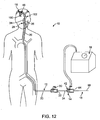
- Fig. 1 illustrates an exemplary embodiment of a thrombotic removal system 10.
- the thromboembolic removal system 10 includes a guide and occlusion catheter 12, a delivery and aspiration catheter 14, a thromboembolic disrupter or separator 16, and an aspiration pump 18.
- the thromboembolic removal system 10 advantageously provides the ability to restore patency to and remove a thromboembolism from a cerebral artery within a patient while overcoming the drawbacks and limitations of the prior art.
- the guide and occlusion catheter 12 includes a tubular catheter member 20 having a main lumen 22 extending between a proximal end 24 and a distal end 26.
- the catheter member 20 may be constructed from any number of compositions having suitable biocompatibility and strength characteristics, and may be dimensioned in any number of suitable sizes and lengths depending upon the entry point into the vasculature, the location of the thromboembolism, variances in patient anatomy, arid any extenuating circumstances.
- the catheter member 20 may be constructed from nylon with embedded stainless steel braid and dimensioned having a length ranging from 70 cm to 110 cm and a diameter ranging from 5 French (0.065 inch, 1.651mm) to 9 French (0.117 inch, 2.9718mm).
- a balloon occlusion member 28 is disposed at or near the distal end 26.
- an inflation port 30 is provided in fluid communication with the occlusion member 28 via at least one lumen (not shown) disposed within the wall of the tubular catheter member 20.
- a seal 32 is provided for passing the delivery and aspiration catheter 14 through the main lumen 22 of the guide and occlusion catheter 12 in leak-free, hemostatic fashion.
- the delivery and aspiration catheter 14 includes a tubular catheter element 34 having a main lumen 36 extending between a distal end 38 and a proximal end 40.
- the catheter member 34 may be constructed from any number of compositions having suitable biocompatibility and strength characteristics, and may be dimensioned in any number of suitable sizes and lengths depending upon the entry point into the vasculature, the location of the thromboembolism, variances in patient anatomy, and any extenuating circumstance.
- the catheter member 34 maybe constructed from pebax with embedded stainless steel braid and dimensioned having a length ranging from 130 cm to 170 cm and a diameter ranging from 2.5 French (0.032 inch, 0.8128mm) to 5 French (0.065 inch, 1.651mm).
- the delivery and aspiration catheter 14 also includes a hub assembly 42 coupled to the proximal end 40 for the purpose of coupling the lumen 36 to the aspiration pump 18.
- the hub assembly 42 also includes a seal 44 for allowing the passage of the thromboembolic separator 16 (as well as any pushing devices to deploy a receiver element 46, as will be discussed below) through the lumen 36 in leak-free, hemostatic fashion.
- the lumen is preferably coated with PTFE or another of the various suitable lubricious materials known in the part.
- the thromboembolic receiver element 46 is capable of being restrained in a withdrawn or undeployed state within the lumen 36 ( Fig. 2 ) and selectively pushed out and/or unsheathed from the distal end 38 into a deployed state ( Fig. 3 ).
- the thromboembolic receiver 46 may be constructed from any number of compositions having suitable biocompatibility and strength characteristics, and may be dimensioned in any number of suitable sizes and lengths depending upon the location of the thromboembolism, variances in patient anatomy, and the size and shape of the thiomboembolism. As best viewed in Figs.
- the thromboembolic receiver 46 is formed from a plurality of strut members 47, which upon being deployed, create a multitude of generally diamond-shaped openings 49 along the periphery of the thromboembolic receiver 46.
- the resulting points at the distal region of the thromboembolic receiver 26 are equipped with blunt tip features 51 to facilitate passage of the thromboembolic receiver 46 through the cerebral artery without snagging or becoming otherwise stuck on the arterial walls or branch vessels leading into the cerebral artery.
- a pusher element 48 may be provided within the catheter element 34 for use in advancing or pushing the receiver element 46 from within the lumen 36 to assume a fully or partially deployed state.
- the pusher element 48 comprises an elongate member 50 of suitable construction (e.g. wire or wire-wound) having a distal abutment 52 dimensioned to contact proximal terminal(s) 54 forming part of (or coupled to) the receiver element 46.
- the pusher element 48 may comprise any number of suitable devices for pushing the receiver element 46 for deployment, including but not limited to a catheter having a distal end dimensioned to contact the proximal terminal(s) 54 of the receiver element 46.
- such a pusher-catheter may have an internally disposed lumen dimensioned to receive and/or pass the thromboembolic separator 16.
- Fig. 4A illustrates a thromboembolic receiver 146 of an exemplary embodiment.
- the thromboembolic receiver 146 may be constructed from any number of compositions having suitable biocompatibility and strength characteristics, and may be dimensioned in any number of suitable sizes and lengths depending upon the location of the thromboembolism, variances in patient anatomy, and the size and shape of the thromboembolism.
- the thromboembolic receiver 146 is constructed from Nitinol with "shape memory" or superelastic characteristics. In this fashion, the thromboembolic receiver 146 is capable of being retained in a constrained form or shape prior to deployment.
- the receiver may be formed by laser cutting features into a length of Nitinol tubing, and then chemically etching and shape-setting the material one or more times using methods known to those skilled in the art.
- receiver 146 is mounted to an elongate member 151 preferably proportioned to extend through lumen 36 ( Fig. 1 ) of the delivery and aspiration catheter 14.
- Strut members or "legs" 162 extend between receiver 146 and elongate member 151 using bonding, shrink tubing, or other known methods.
- member 151 is an elongate rod, catheter, wire or other elongate member.
- the thromboembolic receiver 146 is proportioned so that it may be constrained in a compressed position within the delivery and aspiration catheter 14 (in a manner similar to that shown in Figs. 1-3 ).
- the elongate member 151 may be the delivery and aspiration catheter 14, in which case the receiver 146 and delivery and aspiration catheter 14 are proportioned to extend through the guide and occlusion catheter 12.
- the thromboembolic receiver 146 may be automatically deployed-d'une to the shape memory or superelastic characteristics of Nitinol-by simply advancing the thromboembolic receiver 146 out of the element constraining it in the undeployed state (e.g.. tube guide and occlusion catheter 12 or the delivery and aspiration catheter 14). Once deployed, the thromboembolic receiver 146 may be employed to retrieve a thromboembolism.
- the dimensions of the receiver 146 are preferably selected such that when it is in an expanded condition at body temperature, the exterior surface of the distal portion of the receiver contacts the surround walls of the blood vessel.
- the receiver may expand to a maximum outer diameter of approximately 2-6 mm, and more preferably 2-5 mm.
- a maximum outer diameter in the range of approximately 6-9 mm may be suitable.
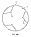
- the thromboembolic receiver 146 may be formed having any variety of suitable geometries and features. According to one exemplary embodiment shown in Figs. 4A and 5 , the thromboembolic receiver 146 is formed from a plurality of strut members, which upon being deployed, create a multitude of generally rectangular openings 149 (best viewed in Fig. 5 ) along the periphery of the thromboembolic receiver 146. This is accomplished, by way of example, by providing a plurality of longitudinal strut members or "standards" 150 (which are generally parallel to the longitudinal axis of the delivery and aspiration catheter 14), and a plurality of transverse strut members 152 (which extend generally perpendicularly between the adjacent standards). In an exemplary embodiment, the strut members collectively define a generally cylindrical distal portion having a central lumen 147 as shown in Fig. 4B .
- the transverse strut members 152 may include any number of curves or undulations, such as curves 153 a shown near the points of intersection between the transverse strut members 152 and the standards 150, as well as the curves 153 b midway between the points of intersection as shown in Fig. 5 .
- Such curves or undulations help allow the thromboembolic receiver 146 to fold into a compressed or constrained state, which is required in order to dispose the thromboembolic receiver 146 within the delivery and aspiration catheter 14 or within the guide and occlusion catheter 12.
- the transverse strut members 152 form, in an exemplary embodiment, a proximal cuff 154 Located closest to the delivery and aspiration catheter 14, a distal cuff 156 located at the distal or open end of the thromboembolic receiver 146, and a middle cuff 158 located at some point between the proximal and distal cuffs.
- Each cuff (proximal 154, middle 158, and distal 156) is a circumferential ring designed to enhance the structural support and stability of the thromboembolic receiver 146, as well as to aid in maintaining the thromboembolic receiver 146 in a desired shape upon deployment (for improved apposition to the vessel wall to optimize the thromboembolic retrieval).
- the structural support provided by the cuffs 154-158 may be augmented by providing one or more stabilizing strut members 160 within one or more of the generally rectangular openings 149.
- these stabilizing strut members 160 may take the form of a "V" extending from either the proximal end or distal end of a given generally rectangular opening 149 within the thromboembolic receiver 146.
- such "V" shaped stabilizing strut members 160 are provided within the proximal and distal set of generally rectangular openings 149 within the thromboembolic receiver 146. This advantageously adds to the structural stability of the proximal and distal regions of the thromboembolic receiver 146.
- the stabilizing strut members 160 preferably include folding regions or apexes 169 that allow them to fold at the apexes 169 (see arrows A in Fig. 5 ) when the receiver is compressed into the collapsed position. Additionally, the receiver is preferably constructed so as to permit the strut members 160 to fold in the region where they intersect with other elements forming the receiver (e.g. in the Fig. 5 , the region of intersection between strut members 160 and standards 150).
- relative flexibility is provided at the junction between the thromboembolic receiver 146 and the elongate member 151 (or the distal end of the delivery and aspiration catheter 14). This is accomplished, by way of example only, by providing the plurality of connector strut members or "legs"162 extending between the proximal cuff and the elongate member 151 to include (as best viewed in Fig. 5 ) a flex region 164 near the distal end of the elongate member 151.
- the flex regions 164 may be formed into any shape that will add flexibility to the strut members 162 without comprising the user's ability to transmit axial forces along the length of the strut members 162.
- the flex regions 164a may comprise a plurality of meandering "S" shaped struts 166 a at the proximal ends of the connector struts 162.
- a flex region or spring region 168 ( FIG. 5 ) (which may comprise one of more "S" shaped curves or other shapes designed to provide flexibility while maintaining adequate column strength) may be provided at the junction between adjacent longitudinal strut members or standards 150.
- such flex regions 164, 168 are advantageous in that they allow the thromboembolic receiver 146 to better track and follow tortuous vessels without sacrificing needed column strength.
- the thromboembolic receiver 146 may also include a variety of features to augment engagement between the thromboembolic receiver 146 and the thromboembolism. This may be accomplished, by way of example only, by providing a plurality of engagement elements 170 on the thromboembolic receiver. As best viewed in Figs. 4A , 4B and 5 , the engagement elements 170 may, according to one exemplary embodiment, take the form of a "V" shaped structure coupled at or near the distal end of the thromboembolic receiver 146 and extending between adjacent standards 150. The engagement elements preferably angle into the lumen 147 of the thromboembolic receiver (see Figs.
- engagement elements 170 may be employed. In one exemplary embodiment, three (3) separate engagement elements 170 may be employed, each being disposed one hundred and twenty (120) degrees from one another along the periphery of the thromboembolic receiver 146. In an exemplary embodiment, the engagement elements 170 take the form of a plurality of the stabilizing strut members 160 as shown in Figs. 4A and 5 .
- the engagement elements 170 may be deployed automatically when the thiomboembolic receiver 146 is deployed (as shown in Fig. 4-5 ). As shown in Fig. 7 , the engagement elements 170 a may also be selectively deployed at any point following the deployment of the thromboembolic receiver 146 a . According to the Fig. 7 , the selective deployment of the engagement elements 170 a is accomplished by passing one or more elongate elements 172 through the thromboembolic receiver 146 a such that the engagement elements 170 a are prevented from extending medially into the lumen of the thromboembolic receiver 146.
- a user When deployment is desired, a user need only pull the elongate element 172 in a proximal direction (towards the user) until the engagement elements 170 a are set free from the constraint of the elongate elements 172. When this occurs, the "shape memory" or superelastic nature of the engagement elements 170 a will cause them to assume their natural state, extending medially into the lumen of the thromboembolic receiver 146 a . In this fashion, the engagement elements 170 a will engage the thromboembolism and thus aid or enhance the ability of the thromboembolic receiver 146 a to remove a thromboembolism.
- the thromboembolic receiver may be provided with features that allow a surgeon to retract the receiver back into the delivery and aspiration catheter after the receiver has been partially or fully deployed into a blood vessel. This might be necessary if, perhaps, the surgeon receives angiographic or tactile feedback indicating that a separator would be a preferred tool for removal of a particular embolism, or that a receiver of a different size would be more suitable for a particular procedure.
- Fig. 8A illustrates one example of an embodiment of a thromboembolic receiver 146 b that is similar to the receiver 146 of Fig. 4 , but that includes the features that facilitate reloading of the receiver into the delivery and aspiration catheter 14.
- receiver 146 b of the Fig. 8A includes a single, distal, cuff 152 b and a plurality of longitudinal strut members 150b extending proximally from the cuff 152 b .
- Structural support members 160b are arranged in a distal row 171 a adjacent to the cuff 152 b , and a more proximal row 171 b as shown in Fig. 8B . As in the Fig. 4 , a plurality of the structural support members 160 b in the distal row are inwardly biased into the central lumen 147 b of the receiver 146 b so as to function as engagement members 170 b for engaging a thromboembolism.
- strut members 162 b extend distally from the apexes of those of the structural support members 160 b in the distal row 171 a that do not function as engagement members. These strut members 162 b are coupled at an intermediate point to the apexes of longitudinally aligned support members 160 b in the proximal row.
- strut members 162c form the proximal extensions of the longitudinal strut members 150 b and include eyelets 163 at their proximal ends.
- strut members 162 d extend from the apexes of those of the structure support members 160 b in the proximal row that are longitudinally aligned with the engagement members 170 b . Flexibility may be added to the receiver 146 b may constructing some or all of the strut members to include flex regions of the type described in connection with earlier examples (see, e.g. flex regions 168 of Fig. 5 ).
- the receiver 146 b includes a pusher or elongate member 151 b that includes a lumen 165 at its distal end.
- the proximal ends of strut members 162 b and 162 d are positioned within the lumen 165 as shown and are allowed to slide freely within the lumen 165.
- the proximal ends of strut members 162 c are bonded to the exterior surface of the elongate member 151 b using heat shrink tubing 167 or other suitable material.
- the eyelets 163 facilitate bonding by allowing the bonding material to flow into the openings of the eyelets, thereby exposing a larger portion of each strut member 162 c to the bonding material.
- the strut members 162 b and 162 d may be somewhat longer than the strut members 162c at the a proximal end of the receiver, to allow them to be easily identified for insertion into the lumen 165 during assembly.
- the elongate member 151 b is withdrawn in a proximal direction relative to the catheter as shown in Fig. 8C .
- the receiver 146 b moves into the catheter 14, the receiver begins to fold at the apexes of the structural support members 162 b and 162 d in a proximal direction. Folding is more easily accomplished than with the receiver 146 of Fig. 4 due to the fact that certain of the structural support members 160 b are interconnected at their apexes by strut members 162 b .
- the folding of one member 160 b in the proximal row 171 b will facilitate the folding of a corresponding member 160 b in the distal row 171 a .
- the strut members 162 b and 162 d are allowed to slide freely within the lumen 165 of the elongate member 151 b so that they will not resist folding of the embers 160 b during withdrawal of the receiver 146 b into the catheter 14.
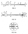
- the thromboembolic separator 16 includes an elongated element 56 having a proximal end 58 and a distal end 60.
- the elongated element 56 may be constructed from any number of compositions having suitable biocompatibility and strength characteristics, and may be dimensioned in any number of suitable sizes and lengths depending upon the entry point in vasculature, the location of the thromboembolism, variances in patient anatomy, and any extenuating circumstances.
- the elongated element 56 may be constructed from stainless steel and/or Nitinol and dimensioned having a length ranging from 150 cm to 200 cm and a diameter ranging from 0.010 inch to 0.021 inch (0.254mm to 0.5334mm).
- a lubricious surface e.g., a PTFE coating, hydrophilic coating, or other suitable coatings
- the elongate element 56 may take the form of a guide wire of the type used in various vascular applications.
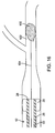
- the elongate element may thus optionally include a coiled distal section 57 ( Fig. 11B ) having sufficient flexibility to prevent trauma to vascular tissues during advancement of the guidewire.
- coiled distal section 57 may have a length in the range of approximately 27-33 cm.
- the coil is preferably positioned around an inner mandrel or core (not shown) of a type commonly found in coiled guidewires.
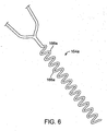
- the "working end” of the separator 16 includes a generally blunt tip element 62 attached or forming part of the distal end 60 of the elongated element 56, and a separator element 64 attached or forming part of the elongated element 56.
- the tip element 62 is preferably dimensioned to pass through or against a thromboembolism so as to soften or fragment the thromboembolism for removal.
- the blunt nature of the tip element 62 is advantageously atraumatic such that it will not cause damage to the interior of the vasculature during use.
- the separator 16 also assists in removing any clogs or flow restrictions that may develop within the lumen 36 due to the passage of thromboembolic material therethrough during aspiration.
- the separator element 64 may take the form of a basket that is generally conical in shape, with an opening 66 facing proximally along the elongated element 56.
- the separator basket 64 is dimensioned to assist in the thromboembolic fragmentation process, as well as to receive such thromboembolic fragments to aid in their removal.
- the separator basket 64 is provided having a web 68 and one or more support members 70.
- the support members 70 are dimensioned to bias the web 68 into the generally open position shown and, if desired, to allow the web 68 to assume a generally closed position (not shown, but generally flush against the elongated element 56) as the separator 16 is passed through delivery and aspiration catheter-style pusher as described above, and/or the thromboembolism itself.
- separator 16 a a is shown in Figs. 11B and 11C , in which like reference numerals are used to identify features similar to those shown in Figs 9, 10 and 11A .
- Separator 16 a differs from separator 16 of Figs. 9, 10 and 11A primarily in the features of the separator element 64 a .
- separator element 64 a is a conical member formed of a polymeric material such as polyurethane or Pebax® polyether block amides, to name a few.
- the separator element 64 a is preferably a solid member, with a surface 65 facing in the proximal direction, and with the taper of the element oriented in a distal direction.
- Surface 65 may be contoured in a variety of ways. For example, surface 65 may be slightly concave as shown in Fig. 11B , substantially planar as shown in Fig. 11C , or slightly convex as shown in Fig. 11D .
- the separator element 64 a is positioned on the coiled distal section 57 of the elongate element 56.
- the pitch of a portion of the coiled section 57 may be decreased in certain regions of the coiled distal section 57. Opening the spacing in the coil in this manner can facilitate adhesion between the polymeric material of the separator element and the coil material during the molding process.
- the spacing between the separator element 64 a and the distal end 60 of the elongate element 56 is preferably long enough to allow the distal-most portion of the elongate element sufficient flexibility to move atraumatically through the vasculature, but short enough to prevent folding of the distal-most portion during advancement of the elongate element 56.
- the distal end of separator element 64 a may be positioned approximately 3-9 mm from the distal end 60. It should be noted that the mandrel or core (not shown) within the coiled section 57 of the elongate element 56 might have a tapered diameter selected to enhance the flexibility of the coiled section.
- a handle member 72 ( Fig. 9 ) is provided at the proximal end 58 of the separator to provide a purchase point for a user to advance and/or manipulate the atraumatic tip element 62 and separator 64/64 a .
- the handle member 72 may be coupled to the elongated element 56 in any suitable fashion, including, but not limited to providing a generally rigid extension (not shown) disposed within the elongated element 56 for the purpose of coupling the two components together. This coupling may be augmented or strengthened through the use of any number of adhesives or fusing techniques.
- the separator 16 may be provided in a variety of different permutations.
- the separator basket 64 of Fig. 11A may be selectively deployed, such as by equipping the separator basket 64 with a mechanism to selectively bias or open the support members 70 from an initial position lying generally flush against the elongated element 56 to a generally radially expanded position (shown with arrows in Fig. 11A ).
- the guide and occlusion catheter 12, the delivery and aspiration catheter 14, the thromboembolic separator 16 and/or the thromboembolic receiver 46 may be provided with any number of features to facilitate the visualization of these elements during introduction and usage, including but not limited to having the distal regions equipped with radiopaque markers for improved radiographic imaging.
- the various components described herein may be provided as part of the system 10 for removing thromboembolic material.
- the thromboembolic removal system 10 may include a guide and occlusion catheter 12, a delivery and aspiration catheter 14, a thromboembolic separator 16/16 a , a thromboembolic receiver (e.g. receiver 46 or 146), and an aspiration pump 18, as well as guidewires and/or other tools appropriate for the procedure.
- multiple receivers 46/146 may be provided, allowing the surgeon to sequentially retrieve several thromboembolisms during the course of a procedure.
- each separate receiver may be provided with a separate delivery and aspiration catheter.
- the system 10 may additionally be provided with instructions for use setting forth any of the various methods of use described herein, or equivalents thereof.
- a first exemplary method the thromboembolic removal system 10 is introduced into the patient's vasculature, such as via the Seldinger technique.
- Fig. 14 illustrates the first step of this process, which involves advancing a guide wire 104 to a point proximal to a thromboembolism 100.
- the guide wire 104 may comprise any number of commercially available guide wires, the operation of which is well known in the art.
- the elongate member 56 ( Fig. 11B ) of the separator 16 functions as the guidewire 104.
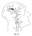
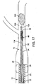
- Fig. 15 illustrates a second step, which involves advancing the guide and occlusion catheter 12 over the guide wire 104 to a point proximal to the thromboembolism.
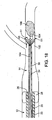
- the next step shown in Fig. 16 , preferably involves inflating the balloon occlusion member 28 so as to arrest the blood flow within the cerebral artery 102 containing the thromboembolism 100.
- the delivery and aspiration catheter 14 is then advanced through the guide and occlusion catheter 12 such that the distal end 38 of the delivery and aspiration catheter 14 is positioned at a point proximal to the thromboembolism 100. This may be facilitated by advancing the delivery and aspiration catheter 14 over the guide wire (not shown but well known in the art) extending through the guide and occlusion catheter 12.
- the thromboembolic receiver 46 is deployed from the distal end 38 of the delivery and aspiration catheter 14.
- the balloon occlusion 28 may be inflated at this point (as opposed to inflating it before the delivery and aspiration catheter 14 is advanced, as shown in Fig. 16 ).
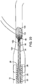
- the delivery and aspiration catheter 14 is then advanced distally-as shown in Fig. 19 -such that the thromboembolic receiver 46 engages and/or envelops (partially or fully) the thromboembolism 100.
- the delivery and aspiration catheter 14 may be withdrawn into the guide and occlusion catheter 12 to remove the thromboembolism 12 from the patient.
- the aspiration pump 18 may be activated to establish negative pressure within the delivery and aspiration catheter 14. In this fashion, negative pressure will be created within the cerebral artery 102 and exerted upon the thromboembolism 100.
- the separator 16 (or the separator 16 a of Figs. 11B-D ) may be employed during this process (e.g. advancing and retracting it within the lumen 36 of the delivery and aspiration catheter 14) to remove any clogs or flow restrictions due to the passage of thromboembolic material through the lumen 36.
- the negative pressure will serve to draw the thromboembolism 10 into (partially or fully) the thromboembolic receiver 46.
- the delivery and aspiration catheter 14 may then be withdrawn into the guide and occlusion catheter 12 to remove the thromboembolism 100 from the patient.
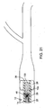
- the thromboembolic separator 16/16 a may be advanced into contact with a portion of the thromboembolism, or completely through the thromboembolism 100 as shown in Fig. 22 , and employed to bias or engage the distal end of the thromboembolism 100. This will increase the surface area of engagement with the thromboembolism 100, which will advantageously allow it to be withdrawn into the guide and occlusion catheter 12 such as by withdrawing the separator 16/16 a and delivery and aspiration catheter 14 simultaneously into the guide and occlusion catheter 12.
- the separator 16/16 a may also be selectively advanced and retracted through the thromboembolism 100 (or that remaining outside the receiver 46). This will serve to break up or otherwise soften the thromboembolism 100. Advancing and retracting the separator 16/16 a also serves to remove any clogs or flow restrictions within the lumen of the delivery and aspiration catheter 14 during the aspiration due to the passage of thromboembolic material through the lumen 36 of the delivery and aspiration catheter 14. In either event, the aspiration pump 18 will draw or bias the thromboembolic fragments 106 or the softened thromboembolism 100 info the thromboembolic receiver 46 and/or into catheter 14. The delivery and aspiration catheter 14 may then be withdrawn such that the thromboembolic receiver 46 is drawn into the guide and occlusion catheter 12 to remove the thromboembolism 100 from the patient.
- Selective advancement of the separator element 64 through the thromboembolism and retraction of the separator element into the delivery and aspiration catheter 14, preferably in combination with aspiration, can additionally be used to carry small "bites" of the thromboembolic material, displacing some material and thus forming a channel in the material as it moves distally. Once the separator element is positioned further into, or distally of, the thromboembolism, some of the displaced material may flow back into this channel. Subsequent retraction of the separator element 64 through the material (e.g. through the refilled channel) will then draw some of the material into the catheter 14.
- the separator element 64 and the catheter 14 are preferably provided with fairly tight tolerances between the diameter of the catheter lumen 36 and the greatest diameter of the separator element 64.
- the outer diameter of separator element 64 and the diameter of lumen 36 may differ by approximately 0.003-0.008 inches (0.0762 - 0.2032mm).
- an initial determination is made concerning whether use of receiver 146 or separator 6 a will first be employed. This determination may be made at random, although preferably the surgeon selects the appropriate tool based on a determination of the likely nature of the thromboembolic material that is to be removed. In particular, the surgeon will assess the patient to determine whether the material is likely to be hard or soft/gelatinous. This assessment might include an evaluation of one or more factors such as the response of the tip of the guidewire or separator when it is brought in contact with thromboembolism, the location of the thromboembolic material, patient symptoms, and/or the manner in which the stroke caused by the thromboembolism is manifesting itself.
- the guide and occlusion catheter 12 is introduced into the patient's vasculature, and the occlusion balloon 28 is inflated to arrest the flow of blood within the vessel (see, for example, Figs. 14-16 ).
- the delivery and aspiration catheter 14 is passed through the guide and occlusion catheter 12 and positioned with its distal end at a location proximal to the thromboembolism 100. If the surgeon elects to use the separator 16 a prior to using the receiver 146, or if the assessment results in a determination that the thromboembolic material is likely to be somewhat soft or gelatinous, the aspiration pump 18 is activated to establish negative pressure within the delivery and aspiration catheter 14, and thus to exert negative pressure exerted upon the thromboembolism 100 to draw embolic material into the catheter 14.
- the separator 16 a is deployed from the distal end of the delivery and aspiration catheter 14 and moved into contact with the thromboembolic material 100 as shown in Fig. 24 .
- the separator may be advanced and retracted multiple times if desired. When advanced and retracted as shown, the separator can facilitate aspiration of the thromboembolic material into the catheter 14 in one of a variety of ways. First, movement of the separator into contact with the thromboembolism can loosen, separate, or soften pieces of thromboembolic material, such that pieces of the thromboembolism can be aspirated into the catheter.
- advancing and retracting the separator 16 a serves to remove any clogs or flow restrictions within the lumen 36 of the delivery and aspiration catheter 14 that might be caused by the passage of thromboembolic material through the lumen 36. Additionally, during retraction of the disrupter 16 a , its proximal surface 35 may push or plunge loosened material towards and/or into the distal end of the catheter 14 for subsequent aspiration out of the body.
- the disrupter 16 a is preferably withdrawn from the catheter 14 and a thromboembolic receiver 146 is passed through the delivery and aspiration catheter 14 and deployed within the blood vessel. If the system is provided with multiple sizes of receivers, the surgeon will select a receiver having an appropriate size for the blood vessel being treated.
- the receiver 146 expands into contact with the surrounding walls of the vessel.
- the walls of the receiver 146 slip around the body 200 to engage and/or envelop (partially or fully) the thromboembolism.
- the engaging elements 170 engage the thromboembolism 200, thereby retaining it within the receiver.
- the delivery and aspiration catheter 14 may be advanced slightly in a distal direction as indicated by arrows in Fig. 27 , so as to "cinch" the strut members 162 towards one another, thus causing the receiver 146 to collapse slightly in a radially inward direction.
- the aspiration pump 18 ( Fig. 1 ) may be activated to facilitate retention of the thromboembolism 200 within the receiver.
- the delivery and aspiration catheter 14, the receiver 146 and the thromboembolism 100 are withdrawn into the guide and occlusion catheter 12 and are withdrawn from the body. If additional thromboembolic material should remain in the blood vessel, a new delivery and aspiration catheter 14 may be passed into the blood vessel, and a new receiver may be deployed through the catheter 14 for retrieving the additional body of thromboembolic material.
- the surgeon may elect to initially deploy the receiver rather than the separator, such as if the initial assessment results in a determination that the thromboembolic material is likely to be hard.
- the method is then carried out utilizing the receiver 146 as described in the preceding paragraph. If it is later determined that residual thromboembolic material (e.g. soft or gelatinous material) is present in the vessel, the receiver 146 is preferably removed from the body, and the separator 16 a is passed through the delivery and aspiration catheter 14.
- the aspiration pump 18 is activated and the separator 16 a is manipulated to facilitate aspiration of the soft material in the manner described above.
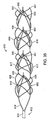
- Figs. 29 and 30 an embodiment of a thromboembolic separator 310 according to the invention is shown.
- the thromboembolic separator of Figs. 29 and 30 combines many of the features of the receivers and separators discussed above, in order to perform as an improved separator.
- Fig. 29 is a perspective view of thromboembolic separator 310.
- Fig. 30 is also a perspective view of thromboembolic separator 310, but is rotated slightly from the view of Fig. 29 in order to reveal characteristics that are not visible in Fig. 29 .
- Fig. 29 can be consulted for an illustration of features that are slightly obstructed in the view of Fig. 30 .
- Thromboembolic separator 310 may be constructed from any number of materials or compositions having suitable biocompatibility and strength characteristics, and may be dimensioned in any number of suitable sizes and lengths depending upon the location of the thromboembolism, variances in patient anatomy, and the size and shape of the thromboembolism.
- the outer diameter of separator 310 in its deployed (radially expanded) configuration may range between 4.6 mm and 5.4 mm to be used in vessels ranging from 3.0 mm and larger; however other device diameters may be suitable according to the invention.
- the length of separator 310 when deployed may vary between 12 mm and 20 mm, but preferably is longer than the length of the thromboembolism, and in this instance is approximately 17mm.
- Separator 310 is constructed from a nickel-titanium alloy (Nitinol®) with "shape memory” or superelastic characteristics. Accordingly, the thromboembolic separator 310 is capable of being retained in a constrained form or shape prior to deployment.
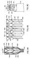
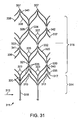
- the separator may be formed by laser cutting features into a length of Nitinol tubing, then chemically etching and shape-setting the material, and then attaching cut features to one another to construct a finished device. For example, a tube of 3.5 mm outer diameter and .0055 inch (0.1397mm) wall thickness may be cut in a predetermined pattern. Examples of suitable patterns are illustrated as flat patterns in Fig. 31 , Fig. 34 and Fig.
- Strut widths that define the elements of separator 310 may vary between 0.0011 inch (0.02794mm) and 0.00165 inch (0.04191mm). Struts may have a broadened region and one or more tapered regions.
- thromboembolic separators illustrated in Figures 29-37 are defined by strut members cut into the tubing, some of which undergo additional processing in the manufacture of the finished device.
- a strut member as used herein is a generic term for a band-like, wire-like, or other elongate element cut out of the tubing in the early steps of manufacture of a separator. Because a separator described herein typically has numerous strut members having varied configurations, other terms are used in the following description to distinguish among strut members and in order to avoid confusion. Nonetheless, a particular strut member will be longitudinal or transverse, curved, undulating, straight deflected inwardly to occupy a lumen of the tubular separator, or the like. The length and width of a strut member may differ from that of another strut member and may perform a different function in the device. An individual strut member may have either a uniform or a varied width along its length.
- Some strut members are configured to define "uprights" or “standards".
- the terms upright or standard are used interchangeably to describe a strut member that extends generally longitudinally (in a direction parallel to a central axis of the tube) along the length of the device.
- An upright or standard will typically confer axial or columnar strength upon the device.
- uprights are typically more or less parallel to one another throughout the length of the device.
- a first set of uprights at the base of the device may be referred to as "legs”.
- An upright or standard may be the same width as or wider than other strut members that define the device's structure.
- An embodiment according to the invention may have any number of uprights, but those described in detail herein typically have between two and four uprights or standards.
- While uprights are more or less parallel to one another,some strut members extend from the uprights or standards at an angle to the upright.
- the angle at which a particular strut member is oriented to a particular upright may vary widely, and the term angle should be understood to mean any angle within the full spectrum greater than 0 degrees and less than 180 degrees, but will most often be between 15 degrees and 75 degrees.
- the strut members that extend from an upright at an angle to the upright meet other strut members attached to an opposite upright and also extending at an angle to the opposite upright.
- the term "apex" is used herein to refer to two strut members that meet at their distal end to form a peak or "apex".
- An apex may be pointed or rounded, may be attached to an upright, to another apex (so that in effect four struts meet at a common apex), or may be free.
- An apex may be slightly “cupped” in a deployed device.
- An apex may be disposed along a "wall" of a separator or, alternatively, may be disposed or deflected to lie within a central "lumen" of the separator. Further, an apex may include an additional extension therefrom.
- An apex that is left free is referred to as an apex, but with an added indication of the relative location of the apex.
- a proximal apex is located at the proximal end of the device
- a distal apex is located at the distal end of the device.
- a body apex is located along the body of the device, and may be numbered consecutively as first body apex, second body apex, and so on, from the proximal end of the device to the distal end of the device.
- An apex that is attached at its distal end to an upright may be referred to as a "fork" at its point of attachment to the upright.
- an apex that is formed where the distal end of an upright divides may be described as "Y-like".
- An apex that may be coupled to another apex in the central lumen of the device is referred to as a "peak", whether the apex is coupled or remains unattached in the finished device.
- An attached pair of peaks, typically disposed within the central lumen of the device, is referred to as a "cage".
- rib is typically a strut member that extends from an upright at an angle to the upright until it meets another rib coming from an opposing upright to define a "peak”.
- a peak may also have a "rib extension” (also referred to herein as an "apex extension”) extending therefrom.
- a peak and its respective rib extension may define a wish-bone like configuration.
- a peak may be attached to another peak or may remain unattached in a finished device. Where a peak is coupled to a second peak, the paired rib peaks are referred to as a "cage”. Ribs, peaks, and rib extensions forming a cage are typically biased into the central lumen of the device when they are coupled with a second pair of ribs, peaks and extensions.
- An “arm” is also a strut that extends from an upright at an angle to the upright. Arms extend generally in a "Y-like configuration" in a distal direction from an upright. Distal to the point where arms divide in a Y-like fashion, two arms meet again at a subsequent upright.
- the term “fork” may be used to describe the point at which two arms meet at a distal upright to define an apex. While all of the foregoing terms refer to struts and apexes, it is hoped that the additional terms enable a clearer distinction among struts and apexes and a clearer description of a device according to the invention.
- separator 310 After material is removed from a Nitinol tube according to a predetermined pattern, and following the final steps to construct separator 310, the structure of separator 310 is a generally skeletal device bearing "internal" elements.
- the body abstracted from the tube has large voids in its "walls” and loosely defines a central axis 330 therethrough.
- the abstract tube has an outer circumference disposed about the central axis.
- the series of internal elements is disposed about central axis 330.
- These internal elements are referred to as engagement cages 350, 351, 352 and 353.
- Separator 310 ( Figs. 29 and 30 ) includes four such engagement cages 350, 351, 352 and 353, but may according to the invention include a greater or lesser number.
- Engagement cages 350, 351, 352 and 353, along with other elements of the device, engage embolic material in a vessel of a subject during use of separator 310, in order that the embolic material may be removed and
- Engagement cages 350, 351, 352 and 353 are framed first by uprights (or standards) 320, 321, 322 and 326 respectively.
- Engagement cage 350 is also framed by proximal apexes 313, and by two pairs of arms 323.
- Proximal apexes 313 may cup slightly in the expanded device.
- Each pair of arms 323 meets to form forks 331 at subsequent uprights 321.
- Engagement cage 351 is also framed by two pairs of arms 325. Each pair of arms 325 meets to form forks 332 at subsequent uprights 322.
- engagement cage 352 is also framed by two pairs of arms 327, which meet to define forks 334 at subsequent uprights 326.
- engagement cage 353 is framed by distal apexes 357. Similar to proximal apexes 313, distal apexes 357 may cup slightly in an expanded device.
- separator 310 is shown mounted to pusher 315, which is proportioned to extend through the lumen of a delivery and aspiration catheter such as the PX400 catheter or other suitable catheters available from Penumbra, Inc. in Alameda, CA.
- a delivery and aspiration catheter such as the PX400 catheter or other suitable catheters available from Penumbra, Inc. in Alameda, CA.
- Other straight lumen catheters having an inner diameter of between 0.025-0.032 inch (0.0635mm - 0.8128mm) may be suitable.
- a suitable pusher catheter may be constructed from Pebax HS tubing or comparable material, available from Zeus Medical of Orangeburg, South Carolina, though other materials and alternative dimensions may be suitable according.
- a separator described herein may in the alternative be mounted to a delivery wire, depending upon the dimensions and requirements of the delivery catheter used to deliver the separator to the treatment site.
- a delivery wire may be of 0.014 inch (0.3556mm) distal diameter and 0.020 inch (0.508mm) proximal diameter stainless steel, Nitinol or other metal, or other suitable dimensions and materials. If mounted upon a delivery wire, separator 310 may be mounted approximately 5 cm from the distal end of the wire, but other configurations are possible. Separator 310 may advantageously be mounted eccentrically to the pusher or delivery wire. Thromboembolic separator 310 is mounted to the distal end of pusher 315 via legs 318.
- Fig. 31 illustrates flat (rolled out) pattern 311. Beginning at its proximal end 312, legs 318 extend distally to form a first set of uprights 320. Proximal apexes 313 are attached between adjacent uprights 320. Base end 314 of separator 310 is thereby defined by legs 318, uprights 320, and proximal apexes 313.
- each upright 320 divides in a Y-like fashion to form a first set of arms 323.
- Each arm 323 extends at an angle to uprights 320, or generally diagonally to meet an adjacent arm 323 at fork 331 as each arm 323 joins a subsequent set of uprights 321 extending therefrom. This pattern, which can be most easily seen in Fig. 31 , repeats until the distal end 359 of separator 310.
- the body 316 of separator 310 is thus defined primarily by successive sets of uprights 320, 321, 322 and 326, successive sets of arms 323, 325 and 327, and forks 331, 332, and 334, where the number of the sets can vary.
- Uprights 320, 321, 322 and 326, arms 323, 325 and 327, and forks 331, 332 and 334 skeletally frame a series of engagement cages, which will be described in detail below.
- Each set of uprights is oriented around the circumference of separator 31 at roughly 90° to its adjacent set of uprights, as most easily seen in Fig. 30 .
- the distal end 359 of separator 320 is defined by distal apexes 357, which in the deployed separator 310 cup slightly and are oriented at approximately 90° about the central axis 330, or around the device's circumference, to proximal apexes 313.
- Distal apexes 357 roughly frame distal most engagement cage 353. This characteristic is most easily seen in Fig. 30 , though other features of separator 310 are obscured when the device is viewed from the perspective illustrated in Fig. 30 .
- each rib 335 extends at angle to uprights 320 at its point of attachment thereto, or somewhat diagonally, to meet an adjacent rib 335 extending from the opposite direction. In this fashion, each rib 335 meets adjacent rib 335 to define a rib peak 317 to form an apex.
- rib extension 340 also extending from each rib peak 317 is rib extension 340. As best viewed in Fig.
- ribs 335, rib peak 317 and rib extensions 340 together define a wish-bone like configuration. This pattern repeats at each subsequent set of uprights 321, 322 and 326, defining subsequent sets of ribs 336, 337 and 338 (and apices), and corresponding rib extensions 341, 342, and 343.
- each rib extension 340, 341 and 343 is biased into central lumen 330 until it meets the respective rib extension 340, 341, or 343 approaching from the opposite side of separator 310.
- Each rib extension 340, 341, 342, and 343 thereby biases each rib 335, 336, 337, and 338 somewhat into central lumen 330.
- Each rib extension 340, 341, 342, and 343 is then mated with its opposing rib extension 340, 341, 342 or 343, and attached thereto via a rib extension joiner 345, 346, 348 or 349, though other suitable means of attachment are within the scope of the invention.
- Separator 310 is shown having four such engagement cages 350, 351, 352, and 353 but a device according to the invention may have a greater or a lesser number.
- Fig. 33 illustrates an alternate embodiment, in which only the proximal most and distal most rib extensions are attached within the central lumen. The intermediate rib extensions remain unattached, leaving opposing rib peaks generally flush with the "walls" of the device. The separator illustrated in Fig. 33 will be discussed in greater detail below.
- separator 310 Prior to delivery and deployment of separator 310, separator 310 will be collapsed, crimped down or otherwise reduced to its delivery configuration and restrained therein by a sheath (not shown). In preparation for treating a subject, the device within its sheath will be loaded in a delivery catheter. During a procedure performed under fluoroscopic visualization, the delivery catheter is tracked to the site of the occlusion. The distal end of the catheter is tracked through the occlusion until the distal tip thereof extends beyond the occlusion. In a slight variation of the exemplary methods described above in relation to alternate embodiments, separator 310 is preferably positioned inside a thrombus prior to deployment, and advantageously will be of a length that is greater than the length of the thrombus.
- the thromboembolic separator 310 is deployed from the distal end of a delivery and aspiration catheter.
- the sheath (not pictured) is then withdrawn to allow partial or complete expansion of the separator within the vessel.
- the separator 310 engages a thromboembolism in a vessel.
- the sheath can then be advanced over thromboembolic separator 310, which readily collapses back into the sheath. A large portion or all of the thromboembolism is thereby removed from the vessel and into the catheter.
- Additional therapeutics such as pharmacologic agents, may be administered before and/or during deployment if desired by the physician.
- additional mechanical means for removal of thromboembolic material may be deployed while the separator is in place within the lumen. Further, expansion of the separator may be increased incrementally during use. And, contrast die may be injected at any point during deployment of the separator to determine the extent of restoration of blood flow.
- an aspiration pump may be activated to establish negative pressure within the delivery and aspiration catheter. In this fashion, negative pressure will be created within the cerebral artery and exerted upon the thromboembolism.
- the delivery sheath may be advanced over at least a portion of the separator and into contact with a portion of the thromboembolism, at least at the proximal end of the separator. This will serve to break up, soften, and/or clear thromboembolic material that is blocking aspiration.
- Advancing and retracting the sheath repeatedly also serves to remove any clogs or flow restrictions within the lumen of the delivery and aspiration catheter during the aspiration due to the passage of thromboembolic material through the lumen of the delivery and aspiration catheter.
- the aspiration pump will draw or bias the thromboembolic fragments or the softened thromboembolism into the aspiration catheter.
- the thromboembolic separator and delivery and aspiration catheter may then be withdrawn such that the separator and aspiration catheter remove the thromboembolism from the patient.
- separator 310 is preferably positioned within a thromboembolism prior to deployment.
- the thromboembolism is located within a curved vessel, and separator 310 will be deployed within a curved vessel.
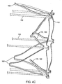
- Clear advantages of separator 310 are illustrated in Fig. 32 , in which separator 310 is shown deployed in a curved vessel model 600. When deployed within a curved tubular vessel, separator 310 resists kinking and collapsing. Further, separator 310 may be partially or fully withdrawn into a delivery sheath (not pictured) without kinking or collapsing, repositioned and redeployed. Some portions of separator 310 may expand into contact with the surrounding walls of the vessel.
- proximal apexes 313 may expand into contact with the vessel wall, depending upon vessel size and morphology.
- distal apexes 357 expand and may or may not contact with the vessel wall.
- Some, all, or portions of some or all of arms 323, 325 and 327, forks 331, 332 and 334, and uprights 320, 321, 322 and 326 may also contact the vessel wall.
- separator 310 generally conforms to the curvature or bend 605 of the vessel.
- Engagement cages 350, 351, 352 and 353 may remain disposed more or less within the central lumen 330, depending upon the degree of curvature of the vessel, vessel morphology, placement of the length of separator 310 with respect to the curvature 605, and other factors. For example, as illustrated in Fig. 32 , portions of some engagement cages 350, 351, 352 and 353 may be disposed in close proximity to the vessel wall. In any event, the function of the engagement cages 350, 351, 352 and 353 is to engage embolic material in order to remove it from the vessel. When in actual use by the physician, the separator may be completely resheathed and removed from the vessel when desired.
- separator 310 Advancement of the sheath and/or retraction of separator 310 will cause separator 310 to return to its collapsed configuration within the sheath. Embolic material will remain engaged to engagement cages 350, 351, 352 and 353, and will consequently also be removed from the vessel, thereby helping to restore blood flow to the vessel. Additional treatment, whether pharmacologic or mechanical, may continue or commence according to the treating practitioners' determination.
- Fig. 33 illustrates an embodiment according to the invention that is similar to that described in Figs. 29-32 , with a few important distinctions.
- a significant distinction of separator 370 from separator 310 is that separator 370 includes only two engagement cages 380 and 383.
- the cut pattern for manufacture of separator 370 of Fig. 32 is the same pattern as that illustrated in Fig. 31 .
- the process of manufacturing separator 370 is the same as that used to manufacture separator 310 except for a few finishing steps. More specifically, in constructing the finished device from pattern 311, only the proximal-most set of rib extensions 340 and the distal-most set of rib extensions 343 are biased into central lumen 385 and attached to one another to form engagement cages 380 and 383.
- Ribs 336 and 337 remain unattached to adjacent ribs and are part of the outer diameter of deployed device 370. And because each set is oriented at roughly 90° to each subsequent set, unattached ribs 335 have generally the same orientation as distal apexes 377, and unattached ribs 337 lie generally oriented with proximal apexes 373.
- the methods of manufacture and exemplary methods of use of separator 370 are otherwise generally the same as those described above in relation to Figs. 29-32 .
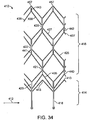
- An alternate thromboembolic separator according to the invention may be constructed using a cut pattern as illustrated in Fig. 34 .
- proximal end 412 includes legs 418.
- a thromboembolic separator manufactured from pattern 410 will be mounted at its proximal end 412, to a pusher (not pictured) via legs 418.
- Legs 418 extend distally from the proximal end 412 to form a first set of uprights 420.
- a row of proximal apexes 413 is attached to uprights 420.
- proximal apexes 413 will surround a central lumen, and further define the base 414 of a separator constructed from pattern 410.
- each upright 420 divides in a Y-like fashion and extends substantially diagonally to form a first set of arms 423.
- Each arm 423 extends diagonally to join an adjacent arm 423 at a fork 440.
- a second set of uprights 421 extends. This pattern repeats until the distal end of cut pattern 410.
- the body 416 of pattern 410 is thus defined primarily by successive sets of uprights 420, 421, 422, and successive sets of arms 423, 425, 427, where the number of both sets can vary Uprights 420, 421, 422, and arms 423, 425, 427 will "surround", or be disposed about, a central axis of a finished device.
- the distal end of pattern 420 is defined by distal apexes 457, which will also surround a central axis of a finished device.
- a rib 435 Just distal to proximal apexes 413 and similarly extending from each upright 420 is a rib 435.
- Each rib 435 extends at an angle to an upright, or somewhat diagonally to meet an adjacent rib 435 extending from the opposite direction. In this fashion, each rib 435 meets adjacent rib 435 to define a rib peak 415.
- rib extension 440 extending from each rib peak 415.
- Ribs 435, rib peaks 415 and rib extensions 440 together define wish-bone like configurations, referred to here as wishbone elements 450.
- This pattern repeats at each subsequent set of uprights 421 and 422, defining subsequent sets of ribs 436, 437 and 438, and corresponding rib extensions 441, 442, and 443.
- rib extensions 440, 441 and 443 will be biased into a central lumen until it meets the respective rib extension 440,441, or 443 approaching from the opposite side. Some or all of rib extensions 440, 441, 442, and 443 will then be mated with its opposing rib extension and attached thereto. Some or all of ribs 435, 436, 437 and 438, together with some or all of rib extensions 440, 441, 442 and 443 will thereby form engagement cages disposed within a central lumen of the finished device.
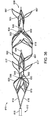
- separator 610 is shown in its deployed configuration in Figs. 35 and 36 .
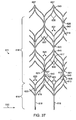
- the flat pattern 611 cut to manufacture separator 610 is illustrated in Fig. 37 .
- the pattern 611 used to manufacture separator 610 is similar to that illustrated in Fig. 31 and described above, with one primary distinction.
- Pattern 611 includes first body apexes 617 and second body apexes 619, in addition to proximal apexes 613 and distal apexes 657. Seen easily in Fig.
- proximal apexes 613, first body apexes 617, second body apexes 619 and distal apexes 657 represent successive sets of apexes.
- each successive set of apexes is oriented at roughly 90° to the preceding set of apexes.
- Separator 610 is otherwise very similar to those described above. Separator 610 when deployed may be between 18-22mm or other suitable length, but in this example is approximately 20mm. Separator 610 is mounted to pusher 615 via legs 618. Separator 610 includes four engagement cages 650, 651, 652 and 653, but may according to the invention include a greater or lesser number. Engagement cages 650, 651, 652 and 653 engage embolic material in a vessel of a subject during use of separator 610.
- legs 618 extend distally to form a first set of uprights 620.
- Proximal apexes 613 are attached to uprights 620.
- Proximal apexes 613 cup slightly in a deployed separator 610 to partially define a central lumen 630.
- Base 614 of separator 610 is thus defined by legs 618, uprights 620, and proximal apexes 613.
- each upright 620 divides in a Y-like fashion to form a first set of arms 623.
- Each arm 623 extends generally diagonally to join an adjacent arm 623 at a fork 630.
- a second set of uprights 621 extends. This pattern repeats until the distal end of pattern 611 or separator 610.
- the body 616 of separator 610 is thus defined primarily by first body apexes 617, second body apexes 619, successive sets of arms 623, 625 and 627, forks 630, 632 and 634, and successive sets of uprights 620, 621, 622 and 626, though a greater or lesser number of sets is within the scope of the invention.
- apexes 613, 617, 619, 657, arms 623, 625 and 627, forks 630, 632 and 634, and uprights 620, 621, 622, 626 skeletally frame the engagement cages and define a central lumen 630.
- Proximal apexes 613, first body apexes 617, second body apexes 619 and distal apexes 657 in the deployed separator 610 cup slightly, and each successive set of apexes is oriented at roughly 90° to its preceding set of apexes.
- rib 635 Just distal to proximal apexes 613 and similarly extending from each upright 620 is a rib 635.
- Each rib 635 extends somewhat diagonally to meet an adjacent rib 635 extending from the opposite direction. In this fashion, each rib 635 meets adjacent rib 635 to define a rib peak 615.
- rib extension 640 extending from each rib peak 615 is rib extension 640.
- ribs 635, rib peaks 615 and rib extensions 640 together define a wish-bone like configuration. This pattern repeats at each subsequent set of uprights 621, 622 and 626, defining subsequent sets of ribs 636, 637 and 638, and corresponding rib extensions 641, 642, and 643.
- each rib extension 640, 641 and 643 is biased into central lumen 630 until it meets the respective rib extension 640, 641, or 643 approaching from the opposite side of separator 610.
- Each rib extension 640, 641, 642, and 643 thereby biases each rib 635,636, 637, and 638 somewhat into central lumen 630.
- Each rib extension 640, 641, 642, and 643 is then mated with its opposing rib extension 640, 641, 642 or 643, and attached thereto via a rib extension joiner 645, 646, 648 or 649, though other suitable means of attachment are within the scope of the invention.
- Separator 610 is shown having four such engagement cages 650, 651, 652, and 653 but a device according to the invention may have a greater or a lesser number.
- separator 610 Prior to delivery and deployment of separator 610, separator 610 will be collapsed, crimped down or otherwise reduced to its delivery configuration and restrained therein by a sheath (not shown). In preparation for treating a subject, the device within its sheath will be loaded in a delivery catheter. During a procedure performed under fluoroscopic visualization, the delivery catheter is tracked to the site of the occlusion. The distal end of the catheter is tracked through the occlusion until the distal tip thereof extends beyond the occlusion. In a slight variation of the methods described in relation to Figs. 25-28 , separator 610 is preferably positioned inside a thrombus prior to deployment, and advantageously will be of a length that is greater than the length of the thrombus.
- the delivery catheter or sheath (not pictured) is then withdrawn to allow partial or complete expansion of the separator within the vessel. Additional therapeutics, such as pharmacologic agents, may be administered before and/or during deployment if desired by the physician. In addition, or alternatively, additional mechanical means for removal of thromboembolic material may be deployed while the separator is in place within the lumen. Further, expansion of the separator may be increased incrementally during use. And, contrast die may be injected at any point during deployment of the separator to determine the extent of restoration of blood flow.
- separator 610 When deployed within a tubular vessel, portions of separator 610 may contact the surrounding walls of the vessel, depending upon vessel size and morphology. More specifically, in addition to contact via the apexes described above, separator 610 may also contact the vessel wall via all or portions of arms 623, 625 and 627 and uprights 620, 621, 622 and 626. Engagement cages 650, 651, 652 and 653 may remain disposed more or less within the central lumen 630, depending upon the degree of curvature of the vessel, vessel morphology, placement of the length of separator 610 with respect to a curvature within a vessel, and other factors.
- the function of the engagement cages 650, 651, .652 and 653 is to engage embolic material in order to remove it from the vessel.
- the separator may be resheathed and removed from the vessel when desired. Retraction of separator 610 will cause separator 610 to return to its collapsed configuration within the sheath (not pictured). Embolic material will remain engaged to engagement cages 650, 651, 652 and 653 and consequently also be removed from the vessel, thereby helping to restore blood flow to the vessel. Additional treatment, whether pharmacologic or mechanical, may continue or commence according to the treating practitioners' determination.
Landscapes
- Health & Medical Sciences (AREA)
- Surgery (AREA)
- Life Sciences & Earth Sciences (AREA)
- Heart & Thoracic Surgery (AREA)
- Nuclear Medicine, Radiotherapy & Molecular Imaging (AREA)
- Vascular Medicine (AREA)
- Engineering & Computer Science (AREA)
- Biomedical Technology (AREA)
- Orthopedic Medicine & Surgery (AREA)
- Medical Informatics (AREA)
- Molecular Biology (AREA)
- Animal Behavior & Ethology (AREA)
- General Health & Medical Sciences (AREA)
- Public Health (AREA)
- Veterinary Medicine (AREA)
- Surgical Instruments (AREA)
Applications Claiming Priority (2)
| Application Number | Priority Date | Filing Date | Title |
|---|---|---|---|
| US13/253,242 US9655633B2 (en) | 2004-09-10 | 2011-10-05 | System and method for treating ischemic stroke |
| PCT/US2012/058695 WO2013052625A1 (en) | 2011-10-05 | 2012-10-04 | System and method for treating ischemic stroke |
Publications (3)
| Publication Number | Publication Date |
|---|---|
| EP2763606A1 EP2763606A1 (en) | 2014-08-13 |
| EP2763606A4 EP2763606A4 (en) | 2015-05-27 |
| EP2763606B1 true EP2763606B1 (en) | 2017-05-03 |
Family
ID=48044141
Family Applications (1)
| Application Number | Title | Priority Date | Filing Date |
|---|---|---|---|
| EP12838884.0A Active EP2763606B1 (en) | 2011-10-05 | 2012-10-04 | System for treating ischemic stroke |
Country Status (10)
| Country | Link |
|---|---|
| US (2) | US9655633B2 (enExample) |
| EP (1) | EP2763606B1 (enExample) |
| JP (1) | JP6078072B2 (enExample) |
| CN (1) | CN104053410B (enExample) |
| AU (1) | AU2012318682A1 (enExample) |
| CA (1) | CA2850788C (enExample) |
| DK (1) | DK2763606T3 (enExample) |
| ES (1) | ES2631361T3 (enExample) |
| IL (1) | IL231799B (enExample) |
| WO (1) | WO2013052625A1 (enExample) |
Families Citing this family (293)
| Publication number | Priority date | Publication date | Assignee | Title |
|---|---|---|---|---|
| DE10233085B4 (de) | 2002-07-19 | 2014-02-20 | Dendron Gmbh | Stent mit Führungsdraht |
| US9655633B2 (en) | 2004-09-10 | 2017-05-23 | Penumbra, Inc. | System and method for treating ischemic stroke |
| US8366735B2 (en) | 2004-09-10 | 2013-02-05 | Penumbra, Inc. | System and method for treating ischemic stroke |
| JP2009512515A (ja) | 2005-10-19 | 2009-03-26 | パルサー バスキュラー インコーポレイテッド | 脈管内をクリッピングし、腔内および組織欠損を修復するための方法およびシステム。 |
| US20070225749A1 (en) | 2006-02-03 | 2007-09-27 | Martin Brian B | Methods and devices for restoring blood flow within blocked vasculature |
| US20120150147A1 (en) * | 2010-12-08 | 2012-06-14 | Penumbra, Inc. | System and method for treating ischemic stroke |
| US10076346B2 (en) | 2007-04-17 | 2018-09-18 | Covidien Lp | Complex wire formed devices |
| US11202646B2 (en) | 2007-04-17 | 2021-12-21 | Covidien Lp | Articulating retrieval devices |
| US10123803B2 (en) | 2007-10-17 | 2018-11-13 | Covidien Lp | Methods of managing neurovascular obstructions |
| US11337714B2 (en) | 2007-10-17 | 2022-05-24 | Covidien Lp | Restoring blood flow and clot removal during acute ischemic stroke |
| CN102036611B (zh) | 2007-12-26 | 2015-01-28 | 拉撒路效应公司 | 取回系统及其使用方法 |
| RU2506912C2 (ru) | 2008-02-22 | 2014-02-20 | Микро Терапьютикс, Инк. | Способы и устройство для восстановления потока |
| US9402707B2 (en) | 2008-07-22 | 2016-08-02 | Neuravi Limited | Clot capture systems and associated methods |
| EP3903696A1 (en) | 2008-09-05 | 2021-11-03 | Pulsar Vascular, Inc. | Systems and methods for supporting or occluding a physiological opening or cavity |
| US20100204672A1 (en) * | 2009-02-12 | 2010-08-12 | Penumra, Inc. | System and method for treating ischemic stroke |
| WO2012009675A2 (en) | 2010-07-15 | 2012-01-19 | Lazarus Effect, Inc. | Retrieval systems and methods for use thereof |
| ES2683943T3 (es) | 2010-10-22 | 2018-09-28 | Neuravi Limited | Sistema de captura y extirpación de coágulos |
| JP6063875B2 (ja) | 2011-02-24 | 2017-01-18 | エキシモ メディカル リミテッド | 組織切除のためのハイブリッドカテーテル |
| US12076037B2 (en) | 2011-03-09 | 2024-09-03 | Neuravi Limited | Systems and methods to restore perfusion to a vessel |
| US11259824B2 (en) | 2011-03-09 | 2022-03-01 | Neuravi Limited | Clot retrieval device for removing occlusive clot from a blood vessel |
| ES3029850T3 (en) | 2011-03-09 | 2025-06-25 | Neuravi Ltd | A clot retrieval device for removing occlusive clot from a blood vessel |
| EP3398539B1 (en) | 2011-05-23 | 2020-08-26 | Covidien LP | Retrieval systems |
| EP2713904B1 (en) | 2011-06-03 | 2018-01-10 | Pulsar Vascular, Inc. | Aneurysm devices with additional anchoring mechanisms and associated systems |
| US10779855B2 (en) | 2011-08-05 | 2020-09-22 | Route 92 Medical, Inc. | Methods and systems for treatment of acute ischemic stroke |
| WO2013022796A2 (en) | 2011-08-05 | 2013-02-14 | Silk Road Medical, Inc. | Methods and systems for treatment of acute ischemic stroke |
| JP6174033B2 (ja) | 2011-10-05 | 2017-08-02 | パルサー バスキュラー インコーポレイテッド | 動脈瘤装置 |
| US12096951B2 (en) | 2011-10-05 | 2024-09-24 | Penumbra, Inc. | System and method for treating ischemic stroke |
| US9072624B2 (en) | 2012-02-23 | 2015-07-07 | Covidien Lp | Luminal stenting |
| US9314248B2 (en) | 2012-11-06 | 2016-04-19 | Covidien Lp | Multi-pivot thrombectomy device |
| US10561509B2 (en) | 2013-03-13 | 2020-02-18 | DePuy Synthes Products, Inc. | Braided stent with expansion ring and method of delivery |
| US10603157B2 (en) | 2013-03-13 | 2020-03-31 | DePuy Synthes Products, Inc. | Braid implant delivery and retraction device with distal engagement |
| CN105208950A (zh) * | 2013-03-14 | 2015-12-30 | 尼尔拉维有限公司 | 一种用于从血管去除堵塞凝块的凝块收取装置 |
| US9433429B2 (en) | 2013-03-14 | 2016-09-06 | Neuravi Limited | Clot retrieval devices |
| PL2967611T3 (pl) | 2013-03-14 | 2019-08-30 | Neuravi Limited | Urządzenie do usuwania ostrych blokad z naczyń krwionośnych |
| WO2014141226A1 (en) | 2013-03-15 | 2014-09-18 | National University Of Ireland | A device suitable for removing matter from inside the lumen and the wall of a body lumen |
| JP6437517B2 (ja) | 2013-03-15 | 2018-12-12 | インセラ セラピューティクス,インク. | 血管治療装置及び方法 |
| CN104068910A (zh) * | 2013-03-26 | 2014-10-01 | 上海微创医疗器械(集团)有限公司 | 血管取栓系统 |
| CN104068911A (zh) * | 2013-03-26 | 2014-10-01 | 上海微创医疗器械(集团)有限公司 | 血管取栓器及取栓装置 |
| US10076399B2 (en) | 2013-09-13 | 2018-09-18 | Covidien Lp | Endovascular device engagement |
| US9592139B2 (en) | 2013-10-04 | 2017-03-14 | Covidien Lp | Stents twisted prior to deployment and untwisted during deployment |
| US9795400B2 (en) | 2013-11-13 | 2017-10-24 | Covidien Lp | Galvanically assisted attachment of medical devices to thrombus |
| US9265512B2 (en) | 2013-12-23 | 2016-02-23 | Silk Road Medical, Inc. | Transcarotid neurovascular catheter |
| US11160572B2 (en) * | 2014-01-03 | 2021-11-02 | Legacy Ventures LLC | Clot retrieval system |
| US9566412B2 (en) | 2014-01-03 | 2017-02-14 | Legacy Ventures LLC | Method of manufacturing a catheter-delivered medical device from a tube |
| US11547446B2 (en) | 2014-01-13 | 2023-01-10 | Trice Medical, Inc. | Fully integrated, disposable tissue visualization device |
| US10285720B2 (en) | 2014-03-11 | 2019-05-14 | Neuravi Limited | Clot retrieval system for removing occlusive clot from a blood vessel |
| DE102014205366B4 (de) * | 2014-03-21 | 2019-03-28 | Coloplast A/S | Fangdrahtinstrument mit Fangdrahtstruktur aus Rohrstück |
| US11154302B2 (en) | 2014-03-31 | 2021-10-26 | DePuy Synthes Products, Inc. | Aneurysm occlusion device |
| US11076860B2 (en) | 2014-03-31 | 2021-08-03 | DePuy Synthes Products, Inc. | Aneurysm occlusion device |
| US20170119410A1 (en) * | 2014-04-29 | 2017-05-04 | Board Of Regents Of The University Of Nebraska | Surgical Snare Device |
| EP3552571B8 (en) | 2014-05-18 | 2024-10-30 | Eximo Medical Ltd. | System for tissue ablation using pulsed laser |
| CN111012443B (zh) * | 2014-05-18 | 2022-09-23 | 遗产投资有限责任公司 | 凝块取出系统 |
| US10792056B2 (en) * | 2014-06-13 | 2020-10-06 | Neuravi Limited | Devices and methods for removal of acute blockages from blood vessels |
| JP6595513B2 (ja) | 2014-06-13 | 2019-10-23 | ニューラヴィ・リミテッド | 血管からの急性閉塞物の除去のための装置 |
| US10265086B2 (en) | 2014-06-30 | 2019-04-23 | Neuravi Limited | System for removing a clot from a blood vessel |
| US9918718B2 (en) | 2014-08-08 | 2018-03-20 | DePuy Synthes Products, Inc. | Embolic coil delivery system with retractable mechanical release mechanism |
| US10206796B2 (en) | 2014-08-27 | 2019-02-19 | DePuy Synthes Products, Inc. | Multi-strand implant with enhanced radiopacity |
| US9782178B2 (en) | 2014-09-19 | 2017-10-10 | DePuy Synthes Products, Inc. | Vasculature occlusion device detachment system with tapered corewire and heater activated fiber detachment |
| EP3017775A1 (en) | 2014-11-07 | 2016-05-11 | National University of Ireland, Galway | A thrombectomy device |
| WO2016083472A1 (en) | 2014-11-26 | 2016-06-02 | Neuravi Limited | A clot retrieval device for removing occlusive clot from a blood vessel |
| US10617435B2 (en) | 2014-11-26 | 2020-04-14 | Neuravi Limited | Clot retrieval device for removing clot from a blood vessel |
| US11253278B2 (en) | 2014-11-26 | 2022-02-22 | Neuravi Limited | Clot retrieval system for removing occlusive clot from a blood vessel |
| ES2577288B8 (es) | 2015-01-13 | 2019-01-10 | Anaconda Biomed S L | Dispositivo para trombectomía |
| EP3639768A1 (en) | 2018-10-16 | 2020-04-22 | Anaconda Biomed, S.L. | A device for extraction of thrombus from a blood vessel and a thrombectomy apparatus |
| US11771446B2 (en) | 2020-10-19 | 2023-10-03 | Anaconda Biomed, S.L. | Thrombectomy system and method of use |
| US11065019B1 (en) | 2015-02-04 | 2021-07-20 | Route 92 Medical, Inc. | Aspiration catheter systems and methods of use |
| US10426497B2 (en) | 2015-07-24 | 2019-10-01 | Route 92 Medical, Inc. | Anchoring delivery system and methods |
| EP3253437B1 (en) | 2015-02-04 | 2019-12-04 | Route 92 Medical, Inc. | Rapid aspiration thrombectomy system |
| CN107405470A (zh) | 2015-02-11 | 2017-11-28 | 柯惠有限合伙公司 | 带可扩张尖端的医疗装置和方法 |
| WO2016197036A1 (en) | 2015-06-03 | 2016-12-08 | Brian Martin | Flexible intravascular treatment devices and associated systems and methods of use |
| US9999493B2 (en) | 2015-08-06 | 2018-06-19 | Kp Medcure, Inc. | Axial lengthening thrombus capture system |
| US9744024B2 (en) | 2015-08-06 | 2017-08-29 | Kp Medcure, Inc. | Axial lengthening thrombus capture system |
| EP3721818B1 (en) | 2015-08-06 | 2025-09-24 | Vascular Medcure, Inc. | Axially lengthening thrombus capture system |
| WO2017053784A1 (en) | 2015-09-25 | 2017-03-30 | Covidien Lp | Medical device delivery system |
| US10537344B2 (en) | 2015-10-23 | 2020-01-21 | Covidien Lp | Rotatable connection between an intervention member and a manipulation member of an endovascular device |
| US10874410B2 (en) | 2015-11-04 | 2020-12-29 | Covidien Lp | Clot removal by adhesion |
| WO2017077393A1 (en) * | 2015-11-04 | 2017-05-11 | Rapid Medical Ltd. | Intraluminal device |
| BR112018010607A2 (pt) * | 2015-11-25 | 2018-11-13 | Neuravi Ltd | dispositivo de remoção de coágulo para remover coágulo oclusivo de um vaso sanguíneo |
| US10226263B2 (en) | 2015-12-23 | 2019-03-12 | Incuvate, Llc | Aspiration monitoring system and method |
| US10052185B2 (en) | 2016-02-12 | 2018-08-21 | Covidien Lp | Vascular device marker attachment |
| US10265089B2 (en) | 2016-02-12 | 2019-04-23 | Covidien Lp | Vascular device visibility |
| CN108697423A (zh) | 2016-02-16 | 2018-10-23 | 伊瑟拉医疗公司 | 抽吸装置和锚定的分流装置 |
| CN113368367B (zh) | 2016-02-24 | 2024-03-29 | 禾木(中国)生物工程有限公司 | 柔性增强的神经血管导管 |
| JP7026645B2 (ja) | 2016-03-17 | 2022-02-28 | トライス メディカル インコーポレイテッド | 凝血塊の排出及び視覚化装置及び使用方法 |
| US11684420B2 (en) | 2016-05-05 | 2023-06-27 | Eximo Medical Ltd. | Apparatus and methods for resecting and/or ablating an undesired tissue |
| US10285710B2 (en) | 2016-06-01 | 2019-05-14 | DePuy Synthes Products, Inc. | Endovascular detachment system with flexible distal end and heater activated detachment |
| ES2834299T3 (es) | 2016-08-17 | 2021-06-17 | Neuravi Ltd | Un dispositivo de extracción de coágulos para eliminar un coágulo oclusivo de un vaso sanguíneo |
| JP6963554B2 (ja) | 2016-08-23 | 2021-11-10 | テルモ株式会社 | 医療デバイス |
| US10076428B2 (en) | 2016-08-25 | 2018-09-18 | DePuy Synthes Products, Inc. | Expansion ring for a braided stent |
| JP2019187458A (ja) * | 2016-08-29 | 2019-10-31 | テルモ株式会社 | 吸引カテーテルおよび吸引システム並びに処置方法 |
| RU2019110141A (ru) * | 2016-09-06 | 2020-10-08 | Ньюрави Лимитед | Устройство извлечения тромба для удаления окклюзионного тромба из кровеносного сосуда |
| US9993257B2 (en) * | 2016-09-07 | 2018-06-12 | NeuroVarc Technologies Inc. | Clot retrieval device for ischemic stroke treatment |
| US10292851B2 (en) | 2016-09-30 | 2019-05-21 | DePuy Synthes Products, Inc. | Self-expanding device delivery apparatus with dual function bump |
| US10517708B2 (en) | 2016-10-26 | 2019-12-31 | DePuy Synthes Products, Inc. | Multi-basket clot capturing device |
| JP7264581B2 (ja) | 2017-01-06 | 2023-04-25 | インセプト、リミテッド、ライアビリティ、カンパニー | 動脈瘤治療装置向けの抗血栓性コーティング |
| AU2018208460B2 (en) | 2017-01-10 | 2023-03-16 | Route 92 Medical, Inc. | Aspiration catheter systems and methods of use |
| US10905853B2 (en) | 2017-01-17 | 2021-02-02 | DePuy Synthes Products, Inc. | System and method for delivering a catheter |
| CN119908793A (zh) | 2017-01-20 | 2025-05-02 | 92号医疗公司 | 用于进入颅内神经脉管系统的快速交换微导管和系统 |
| US10881497B2 (en) | 2017-01-26 | 2021-01-05 | DePuy Synthes Products, Inc. | Composite vascular flow diverter |
| JP7164534B2 (ja) * | 2017-02-08 | 2022-11-01 | バスキュラー メドキュア, インコーポレイテッド | 軸線方向伸長式血栓捕獲システム |
| AU2018224126A1 (en) | 2017-02-23 | 2019-09-12 | DePuy Synthes Products, Inc. | Aneurysm device and delivery system |
| CN107212913B (zh) * | 2017-04-30 | 2020-10-30 | 沈阳新智源医疗用品有限公司 | 一种带有血栓捕获部件的支架取栓器 |
| US10709464B2 (en) | 2017-05-12 | 2020-07-14 | Covidien Lp | Retrieval of material from vessel lumens |
| US11191555B2 (en) | 2017-05-12 | 2021-12-07 | Covidien Lp | Retrieval of material from vessel lumens |
| US10722257B2 (en) | 2017-05-12 | 2020-07-28 | Covidien Lp | Retrieval of material from vessel lumens |
| US11129630B2 (en) | 2017-05-12 | 2021-09-28 | Covidien Lp | Retrieval of material from vessel lumens |
| US11298145B2 (en) | 2017-05-12 | 2022-04-12 | Covidien Lp | Retrieval of material from vessel lumens |
| CN110612057B (zh) | 2017-06-07 | 2022-05-31 | 柯惠有限合伙公司 | 用于检测中风的系统和方法 |
| CN110831523B (zh) | 2017-06-12 | 2022-09-13 | 柯惠有限合伙公司 | 用于给治疗装置装护套的工具以及相关联的系统和方法 |
| US10478322B2 (en) | 2017-06-19 | 2019-11-19 | Covidien Lp | Retractor device for transforming a retrieval device from a deployed position to a delivery position |
| US10575864B2 (en) | 2017-06-22 | 2020-03-03 | Covidien Lp | Securing element for resheathing an intravascular device and associated systems and methods |
| US10342686B2 (en) | 2017-08-10 | 2019-07-09 | Covidien Lp | Thin film mesh hybrid for treating vascular defects |
| CA3195810A1 (en) | 2017-10-16 | 2022-04-21 | Michael Bruce Horowitz | Clot removal methods and devices with multiple independently controllable elements |
| US10258357B1 (en) | 2017-10-16 | 2019-04-16 | Michael Bruce Horowitz | Catheter based retrieval device with proximal body having axial freedom of movement |
| US12201315B2 (en) | 2017-10-16 | 2025-01-21 | Retriever Medical, Inc. | Clot removal methods and devices with multiple independently controllable elements |
| US10835398B2 (en) | 2017-11-03 | 2020-11-17 | Covidien Lp | Meshes and devices for treating vascular defects |
| AU2018364666B2 (en) | 2017-11-09 | 2023-11-09 | Contego Medical, Inc. | Thrombectomy device and methods of use |
| US10709463B2 (en) | 2017-12-11 | 2020-07-14 | Covidien Lp | Electrically enhanced retrieval of material from vessel lumens |
| US12318126B2 (en) | 2021-06-25 | 2025-06-03 | Covidien Lp | Current generator for a medical treatment system |
| US11058444B2 (en) | 2017-12-11 | 2021-07-13 | Covidien Lp | Electrically enhanced retrieval of material from vessel lumens |
| US11974752B2 (en) | 2019-12-12 | 2024-05-07 | Covidien Lp | Electrically enhanced retrieval of material from vessel lumens |
| US12004803B2 (en) | 2021-03-15 | 2024-06-11 | Covidien Lp | Thrombectomy treatment system |
| US10806462B2 (en) | 2017-12-21 | 2020-10-20 | DePuy Synthes Products, Inc. | Implantable medical device detachment system with split tube and cylindrical coupling |
| US10751065B2 (en) | 2017-12-22 | 2020-08-25 | DePuy Synthes Products, Inc. | Aneurysm device and delivery system |
| USD847864S1 (en) | 2018-01-22 | 2019-05-07 | Insera Therapeutics, Inc. | Pump |
| US10905430B2 (en) | 2018-01-24 | 2021-02-02 | DePuy Synthes Products, Inc. | Aneurysm device and delivery system |
| CN111818870B (zh) | 2018-03-13 | 2023-12-08 | 泰尔茂株式会社 | 除去设备及除去系统 |
| US10918390B2 (en) | 2018-03-30 | 2021-02-16 | DePuy Synthes Products, Inc. | Helical balloon assist device and method for using the same |
| US10786259B2 (en) | 2018-03-30 | 2020-09-29 | DePuy Synthes Products, Inc. | Split balloon assist device and method for using the same |
| US10806461B2 (en) | 2018-04-27 | 2020-10-20 | DePuy Synthes Products, Inc. | Implantable medical device detachment system with split tube |
| US11395665B2 (en) | 2018-05-01 | 2022-07-26 | Incept, Llc | Devices and methods for removing obstructive material, from an intravascular site |
| CN119405388A (zh) | 2018-05-01 | 2025-02-11 | 因赛普特有限责任公司 | 用于从血管内部位去除闭塞性物质的装置和方法 |
| ES3009763T3 (en) | 2018-05-17 | 2025-03-31 | Route 92 Medical Inc | Aspiration catheter systems |
| US11596412B2 (en) | 2018-05-25 | 2023-03-07 | DePuy Synthes Products, Inc. | Aneurysm device and delivery system |
| US11058430B2 (en) | 2018-05-25 | 2021-07-13 | DePuy Synthes Products, Inc. | Aneurysm device and delivery system |
| US10939915B2 (en) | 2018-05-31 | 2021-03-09 | DePuy Synthes Products, Inc. | Aneurysm device and delivery system |
| US10667833B2 (en) | 2018-06-08 | 2020-06-02 | Neuravi Limited | Guidewire with an atraumatic clot-circumventing configured distal end for use in an endovascular medical system |
| US10898216B2 (en) | 2018-06-13 | 2021-01-26 | DePuy Synthes Products, Inc. | Vasculature obstruction capture device |
| US10939931B2 (en) * | 2018-06-19 | 2021-03-09 | Stryker Corporation | Embolectomy device having multiple embolectomy structures |
| US11160571B2 (en) | 2018-06-22 | 2021-11-02 | Covidien Lp | Electrically enhanced retrieval of material from vessel lumens |
| WO2020010310A1 (en) | 2018-07-06 | 2020-01-09 | Imperative Care, Inc. | Sealed neurovascular extendable catheter |
| US11471582B2 (en) | 2018-07-06 | 2022-10-18 | Incept, Llc | Vacuum transfer tool for extendable catheter |
| US10531883B1 (en) | 2018-07-20 | 2020-01-14 | Syntheon 2.0, LLC | Aspiration thrombectomy system and methods for thrombus removal with aspiration catheter |
| AU2019204522A1 (en) | 2018-07-30 | 2020-02-13 | DePuy Synthes Products, Inc. | Systems and methods of manufacturing and using an expansion ring |
| US10905431B2 (en) | 2018-08-03 | 2021-02-02 | DePuy Synthes Products, Inc. | Spiral delivery system for embolic braid |
| US10456280B1 (en) | 2018-08-06 | 2019-10-29 | DePuy Synthes Products, Inc. | Systems and methods of using a braided implant |
| US10278848B1 (en) | 2018-08-06 | 2019-05-07 | DePuy Synthes Products, Inc. | Stent delivery with expansion assisting delivery wire |
| US11051825B2 (en) | 2018-08-08 | 2021-07-06 | DePuy Synthes Products, Inc. | Delivery system for embolic braid |
| US10813780B2 (en) | 2018-08-08 | 2020-10-27 | DePuy Synthes Products, Inc. | Intraluminal implant delivery system and method |
| US10842498B2 (en) | 2018-09-13 | 2020-11-24 | Neuravi Limited | Systems and methods of restoring perfusion to a vessel |
| KR20200033757A (ko) | 2018-09-20 | 2020-03-30 | 디퍼이 신테스 프로덕츠, 인코포레이티드 | 형상화된 와이어를 갖는 스텐트 |
| US11123077B2 (en) | 2018-09-25 | 2021-09-21 | DePuy Synthes Products, Inc. | Intrasaccular device positioning and deployment system |
| US11406416B2 (en) | 2018-10-02 | 2022-08-09 | Neuravi Limited | Joint assembly for vasculature obstruction capture device |
| US11253287B2 (en) | 2018-10-04 | 2022-02-22 | Neuravi Limited | Retrograde blood flow occlusion flushing device |
| US11076861B2 (en) | 2018-10-12 | 2021-08-03 | DePuy Synthes Products, Inc. | Folded aneurysm treatment device and delivery method |
| US11406392B2 (en) | 2018-12-12 | 2022-08-09 | DePuy Synthes Products, Inc. | Aneurysm occluding device for use with coagulating agents |
| US11147562B2 (en) | 2018-12-12 | 2021-10-19 | DePuy Synthes Products, Inc. | Systems and methods for embolic implant detachment |
| US11272939B2 (en) | 2018-12-18 | 2022-03-15 | DePuy Synthes Products, Inc. | Intrasaccular flow diverter for treating cerebral aneurysms |
| US11039944B2 (en) | 2018-12-27 | 2021-06-22 | DePuy Synthes Products, Inc. | Braided stent system with one or more expansion rings |
| JP7004487B1 (ja) | 2019-01-11 | 2022-01-24 | アナコンダ バイオメド エス エル | 医療装置をカテーテル内に装填する装置と方法 |
| US11134953B2 (en) | 2019-02-06 | 2021-10-05 | DePuy Synthes Products, Inc. | Adhesive cover occluding device for aneurysm treatment |
| US11273285B2 (en) | 2019-02-07 | 2022-03-15 | DePuy Synthes Products, Inc. | Ancillary device for detaching implants |
| JP7483409B2 (ja) | 2019-03-04 | 2024-05-15 | ニューラヴィ・リミテッド | 作動血塊回収カテーテル |
| US11382633B2 (en) | 2019-03-06 | 2022-07-12 | DePuy Synthes Products, Inc. | Strut flow diverter for cerebral aneurysms and methods for preventing strut entanglement |
| US11612430B2 (en) | 2019-03-19 | 2023-03-28 | Covidien Lp | Electrically enhanced retrieval of material from vessel lumens |
| US11337706B2 (en) | 2019-03-27 | 2022-05-24 | DePuy Synthes Products, Inc. | Aneurysm treatment device |
| US11185334B2 (en) | 2019-03-28 | 2021-11-30 | DePuy Synthes Products, Inc. | Single lumen reduced profile occlusion balloon catheter |
| US11766539B2 (en) | 2019-03-29 | 2023-09-26 | Incept, Llc | Enhanced flexibility neurovascular catheter |
| US11051928B2 (en) | 2019-04-11 | 2021-07-06 | Neuravi Limited | Floating carotid filter |
| US11571553B2 (en) | 2019-05-09 | 2023-02-07 | Neuravi Limited | Balloon guide catheter with thermally expandable material |
| US11607531B2 (en) | 2019-05-09 | 2023-03-21 | Neuravi Limited | Balloon catheter with venting of residual air in a proximal direction |
| US11931522B2 (en) | 2019-05-09 | 2024-03-19 | Neuravi Limited | Inflation lumen kink protection and balloon profile |
| US11957855B2 (en) | 2019-05-09 | 2024-04-16 | Neuravi Limited | Balloon guide catheter with positive venting of residual air |
| USD959659S1 (en) | 2019-05-10 | 2022-08-02 | DePuy Synthes Products, Inc. | Implant release handle |
| US10653425B1 (en) | 2019-05-21 | 2020-05-19 | DePuy Synthes Products, Inc. | Layered braided aneurysm treatment device |
| US11602350B2 (en) | 2019-12-05 | 2023-03-14 | DePuy Synthes Products, Inc. | Intrasaccular inverting braid with highly flexible fill material |
| US11607226B2 (en) | 2019-05-21 | 2023-03-21 | DePuy Synthes Products, Inc. | Layered braided aneurysm treatment device with corrugations |
| US11497504B2 (en) | 2019-05-21 | 2022-11-15 | DePuy Synthes Products, Inc. | Aneurysm treatment with pushable implanted braid |
| US12446886B2 (en) | 2019-05-21 | 2025-10-21 | DePuy Synthes Products, Inc. | Semispherical braided aneurysm treatment system and method |
| US11278292B2 (en) | 2019-05-21 | 2022-03-22 | DePuy Synthes Products, Inc. | Inverting braided aneurysm treatment system and method |
| US11413046B2 (en) | 2019-05-21 | 2022-08-16 | DePuy Synthes Products, Inc. | Layered braided aneurysm treatment device |
| US11672542B2 (en) | 2019-05-21 | 2023-06-13 | DePuy Synthes Products, Inc. | Aneurysm treatment with pushable ball segment |
| US11191558B2 (en) | 2019-06-12 | 2021-12-07 | Covidien Lp | Retrieval of material from corporeal lumens |
| US11523838B2 (en) | 2019-06-12 | 2022-12-13 | Covidien Lp | Retrieval of material from corporeal lumens |
| US11406403B2 (en) | 2019-06-14 | 2022-08-09 | Neuravi Limited | Visibility of mechanical thrombectomy device during diagnostic imaging |
| US11109939B2 (en) | 2019-06-14 | 2021-09-07 | DePuy Synthes Products, Inc. | Intravascular devices with radiopaque body markers |
| US11253265B2 (en) | 2019-06-18 | 2022-02-22 | DePuy Synthes Products, Inc. | Pull wire detachment for intravascular devices |
| US11207494B2 (en) | 2019-07-03 | 2021-12-28 | DePuy Synthes Products, Inc. | Medical device delivery member with flexible stretch resistant distal portion |
| US11426174B2 (en) | 2019-10-03 | 2022-08-30 | DePuy Synthes Products, Inc. | Medical device delivery member with flexible stretch resistant mechanical release |
| US11266427B2 (en) | 2019-07-10 | 2022-03-08 | Neuravi Limited | Self-expanding intravascular medical device |
| US11266426B2 (en) | 2019-07-10 | 2022-03-08 | DePuy Synthes Products, Inc. | Streamlined treatment of clot removal, angioplasty and prevention of restenosis using a single integrated intravascular device |
| US10792054B1 (en) | 2019-07-11 | 2020-10-06 | Eduardo Lorenzo | Catheter for thromboembolic disease with mechanic waves, injection and ejection |
| US11395675B2 (en) | 2019-07-11 | 2022-07-26 | DePuy Synthes Products, Inc. | Clot retriever cleaning for reinsertion |
| US11529495B2 (en) | 2019-09-11 | 2022-12-20 | Neuravi Limited | Expandable mouth catheter |
| US12376859B2 (en) | 2019-09-17 | 2025-08-05 | DePuy Synthes Products, Inc. | Embolic coil proximal connecting element and stretch resistant fiber |
| US11439403B2 (en) | 2019-09-17 | 2022-09-13 | DePuy Synthes Products, Inc. | Embolic coil proximal connecting element and stretch resistant fiber |
| AU2020366348A1 (en) | 2019-10-15 | 2022-05-12 | Imperative Care, Inc. | Systems and methods for multivariate stroke detection |
| US11712231B2 (en) | 2019-10-29 | 2023-08-01 | Neuravi Limited | Proximal locking assembly design for dual stent mechanical thrombectomy device |
| US20210128183A1 (en) | 2019-10-31 | 2021-05-06 | Neuravi Limited | Thrombectomy and stenting system |
| US11793531B2 (en) | 2019-11-05 | 2023-10-24 | Vascular Medcure, Inc. | Axial lengthening thrombus capture system, tensioning system and expandable funnel catheter |
| US11376013B2 (en) | 2019-11-18 | 2022-07-05 | DePuy Synthes Products, Inc. | Implant delivery system with braid cup formation |
| US11628282B2 (en) | 2019-11-25 | 2023-04-18 | Neuravi Limited | No preparation balloon guide catheter |
| US11779364B2 (en) | 2019-11-27 | 2023-10-10 | Neuravi Limited | Actuated expandable mouth thrombectomy catheter |
| US11839725B2 (en) | 2019-11-27 | 2023-12-12 | Neuravi Limited | Clot retrieval device with outer sheath and inner catheter |
| US11517340B2 (en) | 2019-12-03 | 2022-12-06 | Neuravi Limited | Stentriever devices for removing an occlusive clot from a vessel and methods thereof |
| US11395668B2 (en) | 2019-12-12 | 2022-07-26 | Covidien Lp | Electrically enhanced retrieval of material from vessel lumens |
| CN110974350B (zh) * | 2019-12-17 | 2023-03-17 | 禾木(中国)生物工程有限公司 | 取栓系统 |
| CA3162704A1 (en) | 2019-12-18 | 2021-06-24 | Imperative Care, Inc. | Methods and systems for treating venous thromboembolic disease |
| US11439799B2 (en) | 2019-12-18 | 2022-09-13 | Imperative Care, Inc. | Split dilator aspiration system |
| US11633272B2 (en) | 2019-12-18 | 2023-04-25 | Imperative Care, Inc. | Manually rotatable thrombus engagement tool |
| US11457926B2 (en) | 2019-12-18 | 2022-10-04 | DePuy Synthes Products, Inc. | Implant having an intrasaccular section and intravascular section |
| US11457922B2 (en) | 2020-01-22 | 2022-10-04 | DePuy Synthes Products, Inc. | Medical device delivery member with flexible stretch resistant distal portion |
| US11992241B2 (en) | 2020-01-31 | 2024-05-28 | DePuy Synthes Products, Inc. | System to assist delivery of a mechanical intravascular treatment device |
| US11957354B2 (en) | 2020-02-10 | 2024-04-16 | DePuy Synthes Products, Inc. | Aneurysm implant support device |
| US11432822B2 (en) | 2020-02-14 | 2022-09-06 | DePuy Synthes Products, Inc. | Intravascular implant deployment system |
| US12364397B2 (en) | 2020-02-17 | 2025-07-22 | Covidien Lp | Systems and methods for detecting strokes |
| US12263020B2 (en) | 2020-02-17 | 2025-04-01 | Covidien Lp | Systems and methods for detecting strokes |
| US11944327B2 (en) | 2020-03-05 | 2024-04-02 | Neuravi Limited | Expandable mouth aspirating clot retrieval catheter |
| US11633198B2 (en) | 2020-03-05 | 2023-04-25 | Neuravi Limited | Catheter proximal joint |
| CN118925025A (zh) | 2020-03-10 | 2024-11-12 | 因普瑞缇夫护理公司 | 增强的柔韧性的神经血管导管 |
| CN111317543B (zh) * | 2020-03-23 | 2022-10-25 | 南阳市中心医院 | 一种神经介入多功能支护清除装置 |
| US11883043B2 (en) | 2020-03-31 | 2024-01-30 | DePuy Synthes Products, Inc. | Catheter funnel extension |
| US11759217B2 (en) | 2020-04-07 | 2023-09-19 | Neuravi Limited | Catheter tubular support |
| US11717308B2 (en) | 2020-04-17 | 2023-08-08 | Neuravi Limited | Clot retrieval device for removing heterogeneous clots from a blood vessel |
| US11730501B2 (en) | 2020-04-17 | 2023-08-22 | Neuravi Limited | Floating clot retrieval device for removing clots from a blood vessel |
| US11871946B2 (en) | 2020-04-17 | 2024-01-16 | Neuravi Limited | Clot retrieval device for removing clot from a blood vessel |
| CN111437006B (zh) * | 2020-04-27 | 2022-04-19 | 首都医科大学宣武医院 | 取栓支架及其制备方法、取栓装置 |
| US11523831B2 (en) | 2020-04-30 | 2022-12-13 | DePuy Synthes Products, Inc. | Intrasaccular flow diverter |
| US11737771B2 (en) | 2020-06-18 | 2023-08-29 | Neuravi Limited | Dual channel thrombectomy device |
| US11937836B2 (en) | 2020-06-22 | 2024-03-26 | Neuravi Limited | Clot retrieval system with expandable clot engaging framework |
| US11439418B2 (en) | 2020-06-23 | 2022-09-13 | Neuravi Limited | Clot retrieval device for removing clot from a blood vessel |
| US11395669B2 (en) | 2020-06-23 | 2022-07-26 | Neuravi Limited | Clot retrieval device with flexible collapsible frame |
| CN111658836B (zh) * | 2020-06-24 | 2022-04-26 | 中国人民解放军陆军特色医学中心 | 一种腹腔镜吸引器 |
| US11951026B2 (en) | 2020-06-30 | 2024-04-09 | DePuy Synthes Products, Inc. | Implantable medical device detachment system with flexible braid section |
| US12447319B2 (en) | 2020-07-29 | 2025-10-21 | Neuravi Limited | Enhanced balloon bonding for balloon guide catheters while minimizing outer profiles |
| US20220031341A1 (en) | 2020-07-29 | 2022-02-03 | Neuravi Limited | Adhesive-Free Bonded Balloon for a Balloon Guide Catheter With Minimal Outer Profile |
| US11207497B1 (en) | 2020-08-11 | 2021-12-28 | Imperative Care, Inc. | Catheter with enhanced tensile strength |
| WO2022047215A1 (en) | 2020-08-28 | 2022-03-03 | Covidien Lp | Detection of patient conditions using signals sensed on or near the head |
| US11883610B2 (en) * | 2020-08-31 | 2024-01-30 | Covidien Lp | Aspiration systems and methods, and expanding-mouth catheters |
| US11896250B2 (en) | 2020-08-31 | 2024-02-13 | Covidien Lp | Aspiration systems and methods, and expanding-mouth catheters |
| US12376904B1 (en) | 2020-09-08 | 2025-08-05 | Angiodynamics, Inc. | Dynamic laser stabilization and calibration system |
| US11864781B2 (en) | 2020-09-23 | 2024-01-09 | Neuravi Limited | Rotating frame thrombectomy device |
| JP7607424B2 (ja) * | 2020-09-24 | 2024-12-27 | テルモ株式会社 | 血栓除去デバイス |
| US20220111177A1 (en) | 2020-10-09 | 2022-04-14 | Route 92 Medical, Inc. | Aspiration catheter systems and methods of use |
| US12440646B2 (en) | 2020-11-06 | 2025-10-14 | DePuy Synthes Products, Inc. | Catheter braid wire with variable cross-section shape |
| US11826520B2 (en) | 2020-12-08 | 2023-11-28 | DePuy Synthes Products, Inc. | Catheter designs for enhanced column strength |
| US11786698B2 (en) | 2020-12-08 | 2023-10-17 | DePuy Synthes Products, Inc. | Catheter with textured surface |
| US11937837B2 (en) | 2020-12-29 | 2024-03-26 | Neuravi Limited | Fibrin rich / soft clot mechanical thrombectomy device |
| US12029442B2 (en) | 2021-01-14 | 2024-07-09 | Neuravi Limited | Systems and methods for a dual elongated member clot retrieval apparatus |
| US11872354B2 (en) | 2021-02-24 | 2024-01-16 | Neuravi Limited | Flexible catheter shaft frame with seam |
| WO2022180084A1 (en) * | 2021-02-26 | 2022-09-01 | Anaconda Biomed, Sl | An expandable clot mobilizer device for extraction of an occlusion from a blood vessel |
| WO2022187156A1 (en) | 2021-03-01 | 2022-09-09 | Endovascular Engineering, Inc. | Aspiration devices for treatment of thrombosis including expandable distal ends and systems and methods thereof |
| US12064130B2 (en) | 2021-03-18 | 2024-08-20 | Neuravi Limited | Vascular obstruction retrieval device having sliding cages pinch mechanism |
| CN113020929B (zh) * | 2021-03-24 | 2022-06-21 | 科益展智能装备有限公司 | 一种丝锥的加工工艺方法及丝锥 |
| US11376028B1 (en) | 2021-04-17 | 2022-07-05 | Inquis Medical, Inc. | Devices, systems, and methods for removing obstructive material from body lumens |
| EP4329643A4 (en) | 2021-04-27 | 2025-03-12 | Contego Medical, Inc. | Thrombus aspiration system and methods for controlling blood loss |
| CN113081170B (zh) * | 2021-05-06 | 2022-03-25 | 东南大学泰州生物医药与医疗器械研究院 | 多网兜式取栓支架及多网兜取栓系统 |
| US11963713B2 (en) | 2021-06-02 | 2024-04-23 | Covidien Lp | Medical treatment system |
| US11974764B2 (en) | 2021-06-04 | 2024-05-07 | Neuravi Limited | Self-orienting rotating stentriever pinching cells |
| EP4362828A4 (en) | 2021-06-28 | 2025-05-14 | Inquis Medical, Inc. | Devices and methods for controlling the removal of obstructive substance |
| CN113456173A (zh) * | 2021-07-01 | 2021-10-01 | 吉林大学 | 一种脑神经血管血栓取出装置 |
| US11998213B2 (en) | 2021-07-14 | 2024-06-04 | DePuy Synthes Products, Inc. | Implant delivery with modified detachment feature and pull wire engagement |
| CN113598884B (zh) * | 2021-08-06 | 2022-11-25 | 内蒙古工业大学 | 一种碎栓组件及血管血栓处理装置 |
| US20230047098A1 (en) | 2021-08-12 | 2023-02-16 | Imperative Care, Inc. | Multi catheter method of performing a robotic neurovascular procedure |
| US11944374B2 (en) | 2021-08-30 | 2024-04-02 | Covidien Lp | Electrical signals for retrieval of material from vessel lumens |
| US12369920B2 (en) | 2021-09-22 | 2025-07-29 | DePuy Synthes Products, Inc. | Introducer sheath having an intentional friction zone to hold in position a delivery system suitable for implantable intravascular devices |
| US11937839B2 (en) | 2021-09-28 | 2024-03-26 | Neuravi Limited | Catheter with electrically actuated expandable mouth |
| USD1077996S1 (en) | 2021-10-18 | 2025-06-03 | Imperative Care, Inc. | Inline fluid filter |
| US12011186B2 (en) | 2021-10-28 | 2024-06-18 | Neuravi Limited | Bevel tip expandable mouth catheter with reinforcing ring |
| US12076020B2 (en) | 2021-11-18 | 2024-09-03 | Covidien Lp | Retrieval of material from corporeal lumens |
| US11751881B2 (en) | 2021-11-26 | 2023-09-12 | DePuy Synthes Products, Inc. | Securement wire withstanding forces during deployment of implantable intravascular treatment device using a delivery and detachment system |
| EP4452099B1 (en) * | 2021-12-21 | 2025-11-12 | Anaconda BioMed, SL | An intravascular device with an improved attachment of its elements and a method of manufacturing thereof |
| JP2024544734A (ja) * | 2021-12-24 | 2024-12-03 | ハイドロシジョン・インコーポレーテッド | 展開可能なダイナミックステント及び調節可能な切断ジェットデバイス |
| US11937824B2 (en) | 2021-12-30 | 2024-03-26 | DePuy Synthes Products, Inc. | Implant detachment systems with a modified pull wire |
| US11844490B2 (en) | 2021-12-30 | 2023-12-19 | DePuy Synthes Products, Inc. | Suture linkage for inhibiting premature embolic implant deployment |
| US12220131B2 (en) | 2022-01-06 | 2025-02-11 | DePuy Synthes Products, Inc. | Delivery and detachment system imposing a friction force on a securement wire to minimize movement of an implantable intravascular device |
| US12011171B2 (en) | 2022-01-06 | 2024-06-18 | DePuy Synthes Products, Inc. | Systems and methods for inhibiting premature embolic implant deployment |
| EP4468973A1 (en) | 2022-01-27 | 2024-12-04 | Contego Medical, Inc. | Thrombectomy and aspiration system and methods of use |
| US11937825B2 (en) | 2022-03-02 | 2024-03-26 | DePuy Synthes Products, Inc. | Hook wire for preventing premature embolic implant detachment |
| US12471924B2 (en) | 2022-03-02 | 2025-11-18 | DePuy Synthes Products, Inc. | Flexible feature for embolic implant deployment |
| US12137915B2 (en) | 2022-03-03 | 2024-11-12 | DePuy Synthes Products, Inc. | Elongating wires for inhibiting premature implant detachment |
| US11937826B2 (en) | 2022-03-14 | 2024-03-26 | DePuy Synthes Products, Inc. | Proximal link wire for preventing premature implant detachment |
| US12220139B2 (en) | 2022-03-20 | 2025-02-11 | Von Vascular, Inc. | System, devices and methods for removing obstructions in body lumens |
| JP2025510338A (ja) * | 2022-03-28 | 2025-04-14 | エリクシアー メディカル コーポレイション | 拡張可能遠位先端を伴う吸引カテーテル |
| US12038322B2 (en) | 2022-06-21 | 2024-07-16 | Eximo Medical Ltd. | Devices and methods for testing ablation systems |
| US12402886B2 (en) | 2022-06-23 | 2025-09-02 | DePuy Synthes Products, Inc. | Detachment indicator for implant deployment |
| US12458380B2 (en) | 2022-07-29 | 2025-11-04 | Neuravi Limited | Mechanical thrombectomy device for capture and removal of occlusions |
| US12446888B2 (en) | 2022-08-26 | 2025-10-21 | Depuy Synthes Products, Inc | Twister implant detachment mechanism |
| US12053192B2 (en) | 2022-09-01 | 2024-08-06 | Endovascular Engineering, Inc. | Systems, devices, and methods for aspiration, including expandable structures and rotatable shafts |
| US12396730B2 (en) | 2022-09-28 | 2025-08-26 | DePuy Synthes Products, Inc. | Braided implant with detachment mechanism |
| US20240206897A1 (en) * | 2022-12-22 | 2024-06-27 | Covidien Lp | Systems and methods for restoring blood vessel patency |
| US12471937B2 (en) | 2023-01-25 | 2025-11-18 | Syntheon Pv, Llc | Aspiration thrombectomy systems and methods for thrombus removal with aspiration catheter |
| US20250090182A1 (en) * | 2023-09-14 | 2025-03-20 | Inari Medical, Inc. | Multi-lumen aspiration catheters, and associated systems and methods |
Family Cites Families (156)
| Publication number | Priority date | Publication date | Assignee | Title |
|---|---|---|---|---|
| US4046150A (en) | 1975-07-17 | 1977-09-06 | American Hospital Supply Corporation | Medical instrument for locating and removing occlusive objects |
| DE2729566C3 (de) | 1977-06-30 | 1980-01-03 | Juergen Dr. 4400 Muenster Bennemann | Steinfänger |
| US4643184A (en) * | 1982-09-29 | 1987-02-17 | Mobin Uddin Kazi | Embolus trap |
| US4611594A (en) | 1984-04-11 | 1986-09-16 | Northwestern University | Medical instrument for containment and removal of calculi |
| US5024651A (en) | 1984-05-14 | 1991-06-18 | Surgical Systems & Instruments, Inc. | Atherectomy system with a sleeve |
| US4979939A (en) | 1984-05-14 | 1990-12-25 | Surgical Systems & Instruments, Inc. | Atherectomy system with a guide wire |
| DK151404C (da) * | 1984-05-23 | 1988-07-18 | Cook Europ Aps William | Sammenklappeligt filter til implantation i en patients blodkar |
| US4706671A (en) | 1985-05-02 | 1987-11-17 | Weinrib Harry P | Catheter with coiled tip |
| US4790812A (en) | 1985-11-15 | 1988-12-13 | Hawkins Jr Irvin F | Apparatus and method for removing a target object from a body passsageway |
| CA1293663C (en) | 1986-01-06 | 1991-12-31 | David Christopher Auth | Transluminal microdissection device |
| US4729763A (en) | 1986-06-06 | 1988-03-08 | Henrie Rodney A | Catheter for removing occlusive material |
| US4867141A (en) | 1986-06-18 | 1989-09-19 | Olympus Optical Co., Ltd. | Medical treatment apparatus utilizing ultrasonic wave |
| US4784636A (en) | 1987-04-30 | 1988-11-15 | Schneider-Shiley (U.S.A.) Inc. | Balloon atheroectomy catheter |
| US4898575A (en) | 1987-08-31 | 1990-02-06 | Medinnovations, Inc. | Guide wire following tunneling catheter system and method for transluminal arterial atherectomy |
| US5047040A (en) | 1987-11-05 | 1991-09-10 | Devices For Vascular Intervention, Inc. | Atherectomy device and method |
| US4870953A (en) | 1987-11-13 | 1989-10-03 | Donmicheal T Anthony | Intravascular ultrasonic catheter/probe and method for treating intravascular blockage |
| US4873978A (en) * | 1987-12-04 | 1989-10-17 | Robert Ginsburg | Device and method for emboli retrieval |
| US5011488A (en) | 1988-12-07 | 1991-04-30 | Robert Ginsburg | Thrombus extraction system |
| GB8829182D0 (en) | 1988-12-14 | 1989-01-25 | Univ Birmingham | Surgical instrument |
| US4927426A (en) | 1989-01-03 | 1990-05-22 | Dretler Stephen P | Catheter device |
| GB2238485B (en) * | 1989-11-28 | 1993-07-14 | Cook William Europ | A collapsible filter for introduction in a blood vessel of a patient |
| US5069664A (en) | 1990-01-25 | 1991-12-03 | Inter Therapy, Inc. | Intravascular ultrasonic angioplasty probe |
| US5100424A (en) | 1990-05-21 | 1992-03-31 | Cardiovascular Imaging Systems, Inc. | Intravascular catheter having combined imaging abrasion head |
| US5195954A (en) | 1990-06-26 | 1993-03-23 | Schnepp Pesch Wolfram | Apparatus for the removal of deposits in vessels and organs of animals |
| US5100423A (en) | 1990-08-21 | 1992-03-31 | Medical Engineering & Development Institute, Inc. | Ablation catheter |
| US5248296A (en) | 1990-12-24 | 1993-09-28 | Sonic Needle Corporation | Ultrasonic device having wire sheath |
| US5190561A (en) | 1991-01-23 | 1993-03-02 | Surgical Innovations, Inc. | Tissue and organ extractor |
| US5176687A (en) | 1991-05-10 | 1993-01-05 | Hasson Harrith M | Disposable pouch container for isolation and retrieval of tissues removed at laparoscopy |
| US5273526A (en) | 1991-06-21 | 1993-12-28 | Lake Region Manufacturing Company, Inc. | Vascular occulusion removal devices and method |
| US5135483A (en) | 1991-07-22 | 1992-08-04 | Dow Corning Wright Corporation | Atherectomy device with a removable drive system |
| WO1995014500A1 (en) * | 1992-05-01 | 1995-06-01 | Beth Israel Hospital | A stent |
| US5380273A (en) | 1992-05-19 | 1995-01-10 | Dubrul; Will R. | Vibrating catheter |
| US5324304A (en) * | 1992-06-18 | 1994-06-28 | William Cook Europe A/S | Introduction catheter set for a collapsible self-expandable implant |
| US5643297A (en) | 1992-11-09 | 1997-07-01 | Endovascular Instruments, Inc. | Intra-artery obstruction clearing apparatus and methods |
| US5501694A (en) | 1992-11-13 | 1996-03-26 | Scimed Life Systems, Inc. | Expandable intravascular occlusion material removal devices and methods of use |
| US5423830A (en) | 1993-07-07 | 1995-06-13 | Schneebaum; Cary W. | Polyp retrieval method and associated instrument assembly |
| US5417697A (en) | 1993-07-07 | 1995-05-23 | Wilk; Peter J. | Polyp retrieval assembly with cauterization loop and suction web |
| US5634897A (en) | 1993-10-08 | 1997-06-03 | Lake Region Manufacturing, Inc. | Rheolytic occlusion removal catheter system and method |
| US5476450A (en) | 1993-11-04 | 1995-12-19 | Ruggio; Joseph M. | Apparatus and method for aspirating intravascular, pulmonary and cardiac obstructions |
| JP3647456B2 (ja) * | 1994-04-29 | 2005-05-11 | ボストン・サイエンティフィック・コーポレーション | 医療用人工ステント及びその製造方法 |
| US5522819A (en) | 1994-05-12 | 1996-06-04 | Target Therapeutics, Inc. | Dual coil medical retrieval device |
| US6123715A (en) * | 1994-07-08 | 2000-09-26 | Amplatz; Curtis | Method of forming medical devices; intravascular occlusion devices |
| AU3761995A (en) | 1994-10-03 | 1996-04-26 | Heart Technology, Inc. | Transluminal thrombectomy apparatus |
| US5658296A (en) | 1994-11-21 | 1997-08-19 | Boston Scientific Corporation | Method for making surgical retrieval baskets |
| US6013093A (en) * | 1995-11-28 | 2000-01-11 | Boston Scientific Corporation | Blood clot filtering |
| US5549626A (en) | 1994-12-23 | 1996-08-27 | New York Society For The Ruptured And Crippled Maintaining The Hospital For Special Surgery | Vena caval filter |
| WO1996023446A1 (en) | 1995-02-02 | 1996-08-08 | Boston Scientific Corporation | Surgical wire basket extractor |
| US6350266B1 (en) | 1995-02-02 | 2002-02-26 | Scimed Life Systems, Inc. | Hybrid stone retrieval device |
| US5827229A (en) | 1995-05-24 | 1998-10-27 | Boston Scientific Corporation Northwest Technology Center, Inc. | Percutaneous aspiration thrombectomy catheter system |
| US5938645A (en) | 1995-05-24 | 1999-08-17 | Boston Scientific Corporation Northwest Technology Center Inc. | Percutaneous aspiration catheter system |
| AR001162A1 (es) | 1996-03-06 | 1997-09-24 | Parodi Juan C | Expansor endovascular de posicionamiento no migratorio |
| SE508742C2 (sv) | 1996-03-25 | 1998-11-02 | Safe Conduct Ab | Anordning för användning vid endoskopiska operationer, för att fixera, omsluta, dela upp och föra ut ett preparat |
| US6800080B1 (en) * | 1996-05-03 | 2004-10-05 | Scimed Life Systems, Inc. | Medical retrieval device |
| US6544276B1 (en) | 1996-05-20 | 2003-04-08 | Medtronic Ave. Inc. | Exchange method for emboli containment |
| US5972019A (en) * | 1996-07-25 | 1999-10-26 | Target Therapeutics, Inc. | Mechanical clot treatment device |
| US6015420A (en) | 1997-03-06 | 2000-01-18 | Scimed Life Systems, Inc. | Atherectomy device for reducing damage to vessels and/or in-vivo stents |
| US5843103A (en) | 1997-03-06 | 1998-12-01 | Scimed Life Systems, Inc. | Shaped wire rotational atherectomy device |
| US5814064A (en) | 1997-03-06 | 1998-09-29 | Scimed Life Systems, Inc. | Distal protection device |
| US6761727B1 (en) | 1997-06-02 | 2004-07-13 | Medtronic Ave, Inc. | Filter assembly |
| US6361545B1 (en) | 1997-09-26 | 2002-03-26 | Cardeon Corporation | Perfusion filter catheter |
| US6066149A (en) | 1997-09-30 | 2000-05-23 | Target Therapeutics, Inc. | Mechanical clot treatment device with distal filter |
| US6099534A (en) | 1997-10-01 | 2000-08-08 | Scimed Life Systems, Inc. | Releasable basket |
| US6530923B1 (en) | 1998-02-10 | 2003-03-11 | Artemis Medical, Inc. | Tissue removal methods and apparatus |
| US6602204B2 (en) | 1998-02-10 | 2003-08-05 | Artemis Medical, Inc | Intraoperative tissue treatment methods |
| US6443972B1 (en) * | 1997-11-19 | 2002-09-03 | Cordis Europa N.V. | Vascular filter |
| US6295990B1 (en) | 1998-02-03 | 2001-10-02 | Salient Interventional Systems, Inc. | Methods and systems for treating ischemia |
| US5989210A (en) | 1998-02-06 | 1999-11-23 | Possis Medical, Inc. | Rheolytic thrombectomy catheter and method of using same |
| US6602265B2 (en) | 1998-02-10 | 2003-08-05 | Artemis Medical, Inc. | Tissue separation medical device and method |
| US6482217B1 (en) | 1998-04-10 | 2002-11-19 | Endicor Medical, Inc. | Neuro thrombectomy catheter |
| US6001112A (en) | 1998-04-10 | 1999-12-14 | Endicor Medical, Inc. | Rotational atherectomy device |
| US6666874B2 (en) | 1998-04-10 | 2003-12-23 | Endicor Medical, Inc. | Rotational atherectomy system with serrated cutting tip |
| DE69929182T2 (de) | 1998-04-23 | 2006-09-21 | Boston Scientific Ltd., St. Michael | Medizinische vorrichtung zur bergung von abgetrennten organteilen mittels schlingen |
| US6511492B1 (en) | 1998-05-01 | 2003-01-28 | Microvention, Inc. | Embolectomy catheters and methods for treating stroke and other small vessel thromboembolic disorders |
| US6306163B1 (en) | 1998-08-04 | 2001-10-23 | Advanced Cardiovascular Systems, Inc. | Assembly for collecting emboli and method of use |
| IL125965A (en) | 1998-08-27 | 2003-03-12 | Hendler Shoshan | Apparatus and method for acquisition and retrieval of resected biological specimens |
| US6083259A (en) | 1998-11-16 | 2000-07-04 | Frantzen; John J. | Axially non-contracting flexible radially expandable stent |
| US6165199A (en) | 1999-01-12 | 2000-12-26 | Coaxia, Inc. | Medical device for removing thromboembolic material from cerebral arteries and methods of use |
| US6632236B2 (en) | 1999-03-12 | 2003-10-14 | Arteria Medical Science, Inc. | Catheter having radially expandable main body |
| US6709465B2 (en) * | 1999-03-18 | 2004-03-23 | Fossa Medical, Inc. | Radially expanding ureteral device |
| US6156055A (en) | 1999-03-23 | 2000-12-05 | Nitinol Medical Technologies Inc. | Gripping device for implanting, repositioning or extracting an object within a body vessel |
| WO2000067665A1 (en) * | 1999-05-07 | 2000-11-16 | Salviac Limited | Support frame for embolic protection device |
| US6964672B2 (en) * | 1999-05-07 | 2005-11-15 | Salviac Limited | Support frame for an embolic protection device |
| US6350271B1 (en) | 1999-05-17 | 2002-02-26 | Micrus Corporation | Clot retrieval device |
| US7169154B1 (en) * | 1999-05-25 | 2007-01-30 | Scimedlife Systems, Inc. | Releasable basket and method of making thereof |
| US6068645A (en) | 1999-06-07 | 2000-05-30 | Tu; Hosheng | Filter system and methods for removing blood clots and biological material |
| US6458139B1 (en) | 1999-06-21 | 2002-10-01 | Endovascular Technologies, Inc. | Filter/emboli extractor for use in variable sized blood vessels |
| US20030150821A1 (en) | 1999-07-16 | 2003-08-14 | Bates Mark C. | Emboli filtration system and methods of use |
| US6589263B1 (en) | 1999-07-30 | 2003-07-08 | Incept Llc | Vascular device having one or more articulation regions and methods of use |
| US6203561B1 (en) | 1999-07-30 | 2001-03-20 | Incept Llc | Integrated vascular device having thrombectomy element and vascular filter and methods of use |
| US8257428B2 (en) * | 1999-08-09 | 2012-09-04 | Cardiokinetix, Inc. | System for improving cardiac function |
| US6454775B1 (en) | 1999-12-06 | 2002-09-24 | Bacchus Vascular Inc. | Systems and methods for clot disruption and retrieval |
| US6939361B1 (en) * | 1999-09-22 | 2005-09-06 | Nmt Medical, Inc. | Guidewire for a free standing intervascular device having an integral stop mechanism |
| US6575997B1 (en) * | 1999-12-23 | 2003-06-10 | Endovascular Technologies, Inc. | Embolic basket |
| US6660021B1 (en) | 1999-12-23 | 2003-12-09 | Advanced Cardiovascular Systems, Inc. | Intravascular device and system |
| US6402771B1 (en) * | 1999-12-23 | 2002-06-11 | Guidant Endovascular Solutions | Snare |
| US6702834B1 (en) | 1999-12-30 | 2004-03-09 | Advanced Cardiovascular Systems, Inc. | Embolic protection devices |
| US6361546B1 (en) | 2000-01-13 | 2002-03-26 | Endotex Interventional Systems, Inc. | Deployable recoverable vascular filter and methods for use |
| US6629953B1 (en) * | 2000-02-18 | 2003-10-07 | Fox Hollow Technologies, Inc. | Methods and devices for removing material from a vascular site |
| WO2001062184A2 (en) * | 2000-02-23 | 2001-08-30 | Boston Scientific Limited | Intravascular filtering devices and methods |
| US6719717B1 (en) | 2000-03-17 | 2004-04-13 | Advanced Research & Technology Institute, Inc. | Thrombectomy treatment system and method |
| US6514273B1 (en) | 2000-03-22 | 2003-02-04 | Endovascular Technologies, Inc. | Device for removal of thrombus through physiological adhesion |
| US20010031981A1 (en) | 2000-03-31 | 2001-10-18 | Evans Michael A. | Method and device for locating guidewire and treating chronic total occlusions |
| US6361556B1 (en) * | 2000-04-27 | 2002-03-26 | Endovascular Tech Inc | System and method for endovascular aneurysm repair in conjuction with vascular stabilization |
| AUPQ831500A0 (en) | 2000-06-22 | 2000-07-13 | White, Geoffrey H. | Method and apparatus for performing percutaneous thromboembolectomies |
| US6824545B2 (en) | 2000-06-29 | 2004-11-30 | Concentric Medical, Inc. | Systems, methods and devices for removing obstructions from a blood vessel |
| US6517551B1 (en) | 2000-11-22 | 2003-02-11 | George Mark Driskill | Intravascular foreign object retrieval catheter |
| US6551327B1 (en) | 2001-01-17 | 2003-04-22 | Avtar S. Dhindsa | Endoscopic stone extraction device with improved basket |
| US6610077B1 (en) * | 2001-01-23 | 2003-08-26 | Endovascular Technologies, Inc. | Expandable emboli filter and thrombectomy device |
| US6616676B2 (en) | 2001-04-10 | 2003-09-09 | Scimed Life Systems, Inc. | Devices and methods for removing occlusions in vessels |
| US6500186B2 (en) | 2001-04-17 | 2002-12-31 | Scimed Life Systems, Inc. | In-stent ablative tool |
| US7179275B2 (en) * | 2001-06-18 | 2007-02-20 | Rex Medical, L.P. | Vein filter |
| US8282668B2 (en) * | 2001-06-18 | 2012-10-09 | Rex Medical, L.P. | Vein filter |
| IL159572A0 (en) * | 2001-06-28 | 2004-06-01 | Lithotech Medical Ltd | Foreign body retrieval device |
| JP4567918B2 (ja) * | 2001-07-02 | 2010-10-27 | テルモ株式会社 | 血管内異物除去用ワイヤおよび医療器具 |
| US20030040762A1 (en) | 2001-08-22 | 2003-02-27 | Gerald Dorros | Apparatus and methods for treating stroke and controlling cerebral flow characteristics |
| US6929634B2 (en) | 2001-08-22 | 2005-08-16 | Gore Enterprise Holdings, Inc. | Apparatus and methods for treating stroke and controlling cerebral flow characteristics |
| US6551342B1 (en) * | 2001-08-24 | 2003-04-22 | Endovascular Technologies, Inc. | Embolic filter |
| US8262689B2 (en) * | 2001-09-28 | 2012-09-11 | Advanced Cardiovascular Systems, Inc. | Embolic filtering devices |
| US20040138692A1 (en) * | 2003-01-13 | 2004-07-15 | Scimed Life Systems, Inc. | Embolus extractor |
| US7749243B2 (en) * | 2001-10-19 | 2010-07-06 | Boston Scientific Scimed, Inc. | Embolus extractor |
| US7052500B2 (en) * | 2001-10-19 | 2006-05-30 | Scimed Life Systems, Inc. | Embolus extractor |
| US7018354B2 (en) | 2001-11-08 | 2006-03-28 | El Hassane Tazi | Liposuction devices and methods and surrounding aspiration systems and methods |
| CA2468835A1 (en) | 2001-12-03 | 2003-06-12 | Ekos Corporation | Small vessel ultrasound catheter |
| US7241304B2 (en) * | 2001-12-21 | 2007-07-10 | Advanced Cardiovascular Systems, Inc. | Flexible and conformable embolic filtering devices |
| AU2003220066A1 (en) | 2002-03-06 | 2003-09-22 | Boston Scientific Limited | Medical retrieval device |
| US7128718B2 (en) | 2002-03-22 | 2006-10-31 | Cordis Corporation | Guidewire with deflectable tip |
| US6881218B2 (en) | 2002-05-01 | 2005-04-19 | Angiodynamics, Inc. | Blood clot filter |
| US7195648B2 (en) * | 2002-05-16 | 2007-03-27 | Cordis Neurovascular, Inc. | Intravascular stent device |
| US6830638B2 (en) * | 2002-05-24 | 2004-12-14 | Advanced Cardiovascular Systems, Inc. | Medical devices configured from deep drawn nickel-titanium alloys and nickel-titanium clad alloys and method of making the same |
| US7481823B2 (en) * | 2002-10-25 | 2009-01-27 | Boston Scientific Scimed, Inc. | Multiple membrane embolic protection filter |
| US8591540B2 (en) * | 2003-02-27 | 2013-11-26 | Abbott Cardiovascular Systems Inc. | Embolic filtering devices |
| US7316692B2 (en) * | 2003-08-12 | 2008-01-08 | Boston Scientific Scimed, Inc. | Laser-cut clot puller |
| WO2005025643A2 (en) * | 2003-09-04 | 2005-03-24 | Secant Medical, Llc | Endovascular snare for capture and removal of arterial emboli |
| US20050059993A1 (en) | 2003-09-17 | 2005-03-17 | Kamal Ramzipoor | Embolectomy device |
| WO2005094283A2 (en) | 2004-03-25 | 2005-10-13 | Hauser David L | Vascular filter device |
| DE102004040868A1 (de) * | 2004-08-23 | 2006-03-09 | Miloslavski, Elina | Vorrichtung zur Entfernung von Thromben |
| US20060058837A1 (en) | 2004-09-10 | 2006-03-16 | Arani Bose | System and method for treating ischemic stroke |
| CN100591294C (zh) * | 2004-09-10 | 2010-02-24 | 半影公司 | 用于治疗缺血性中风的系统以及方法 |
| US8366735B2 (en) | 2004-09-10 | 2013-02-05 | Penumbra, Inc. | System and method for treating ischemic stroke |
| US9655633B2 (en) | 2004-09-10 | 2017-05-23 | Penumbra, Inc. | System and method for treating ischemic stroke |
| WO2007067451A2 (en) * | 2005-12-07 | 2007-06-14 | C. R. Bard, Inc. | Vena cava filter with stent |
| WO2007117645A2 (en) | 2006-04-07 | 2007-10-18 | Penumbra, Inc. | Aneurysm occlusion system and method |
| US20080269774A1 (en) | 2006-10-26 | 2008-10-30 | Chestnut Medical Technologies, Inc. | Intracorporeal Grasping Device |
| CN101020074A (zh) | 2007-03-01 | 2007-08-22 | 陈克敏 | 气液消毒杀菌净化装置 |
| US20100256600A1 (en) | 2009-04-04 | 2010-10-07 | Ferrera David A | Neurovascular otw pta balloon catheter and delivery system |
| US8066757B2 (en) | 2007-10-17 | 2011-11-29 | Mindframe, Inc. | Blood flow restoration and thrombus management methods |
| CN102036611B (zh) * | 2007-12-26 | 2015-01-28 | 拉撒路效应公司 | 取回系统及其使用方法 |
| JP2011517607A (ja) * | 2008-04-11 | 2011-06-16 | マインドフレーム, インコーポレイテッド | 脳卒中を処置する医療デバイスの送達のためのモノレール神経マイクロカテーテル、モノレール神経マイクロカテーテルによるプロセス、およびモノレール神経マイクロカテーテルによる製品 |
| DE102008038195A1 (de) * | 2008-08-19 | 2010-02-25 | Phenox Gmbh | Vorrichtung zur Eröffnung okkludierter Blutgefäße |
| JP2012513292A (ja) | 2008-12-23 | 2012-06-14 | シルク・ロード・メディカル・インコーポレイテッド | 急性虚血性脳卒中の治療方法及び治療システム |
| EP2381891B1 (en) * | 2009-01-16 | 2018-04-11 | Novate Medical Limited | A vascular filter device |
| US20100211094A1 (en) * | 2009-02-18 | 2010-08-19 | Cook Incorporated | Umbrella distal embolic protection device |
| US8357179B2 (en) | 2009-07-08 | 2013-01-22 | Concentric Medical, Inc. | Vascular and bodily duct treatment devices and methods |
| DE102010025661A1 (de) * | 2010-02-05 | 2011-08-11 | Acandis GmbH & Co. KG, 76327 | Medizinische Vorrichtung zum Lösen von Konkrementen, Verfahren zum Herstellen einer derartigen Vorrichtung, Behandlungssystem mit einer derartigen Vorrichtung und Verfahren zum Herstellen eines Behandlungssystems |
| ES3029850T3 (en) | 2011-03-09 | 2025-06-25 | Neuravi Ltd | A clot retrieval device for removing occlusive clot from a blood vessel |
| US8715314B1 (en) * | 2013-03-15 | 2014-05-06 | Insera Therapeutics, Inc. | Vascular treatment measurement methods |
-
2011
- 2011-10-05 US US13/253,242 patent/US9655633B2/en active Active
-
2012
- 2012-10-04 ES ES12838884.0T patent/ES2631361T3/es active Active
- 2012-10-04 JP JP2014534706A patent/JP6078072B2/ja active Active
- 2012-10-04 WO PCT/US2012/058695 patent/WO2013052625A1/en not_active Ceased
- 2012-10-04 EP EP12838884.0A patent/EP2763606B1/en active Active
- 2012-10-04 CA CA2850788A patent/CA2850788C/en active Active
- 2012-10-04 AU AU2012318682A patent/AU2012318682A1/en not_active Abandoned
- 2012-10-04 CN CN201280059966.1A patent/CN104053410B/zh active Active
- 2012-10-04 DK DK12838884.0T patent/DK2763606T3/en active
-
2014
- 2014-03-30 IL IL231799A patent/IL231799B/en active IP Right Grant
-
2017
- 2017-04-14 US US15/488,349 patent/US10993731B2/en active Active
Also Published As
| Publication number | Publication date |
|---|---|
| EP2763606A1 (en) | 2014-08-13 |
| CA2850788A1 (en) | 2013-04-11 |
| US20120116440A1 (en) | 2012-05-10 |
| CN104053410A (zh) | 2014-09-17 |
| AU2012318682A1 (en) | 2014-05-29 |
| US20170215902A1 (en) | 2017-08-03 |
| JP6078072B2 (ja) | 2017-02-08 |
| CA2850788C (en) | 2019-06-18 |
| IL231799A0 (en) | 2014-05-28 |
| ES2631361T3 (es) | 2017-08-30 |
| US10993731B2 (en) | 2021-05-04 |
| IL231799B (en) | 2019-07-31 |
| WO2013052625A1 (en) | 2013-04-11 |
| US9655633B2 (en) | 2017-05-23 |
| EP2763606A4 (en) | 2015-05-27 |
| DK2763606T3 (en) | 2017-07-17 |
| CN104053410B (zh) | 2017-03-29 |
| JP2014533131A (ja) | 2014-12-11 |
Similar Documents
| Publication | Publication Date | Title |
|---|---|---|
| US12096951B2 (en) | System and method for treating ischemic stroke | |
| EP2763606B1 (en) | System for treating ischemic stroke | |
| EP1799128B1 (en) | System for treating ischemic stroke | |
| US8366735B2 (en) | System and method for treating ischemic stroke | |
| AU2018226388B2 (en) | Devices and systems for thrombus treatment | |
| EP3451953B1 (en) | Internal carotid artery thrombectomy devices | |
| JP2014533131A5 (enExample) | ||
| WO2017062383A1 (en) | Multiple barrel clot removal devices | |
| CN100591294C (zh) | 用于治疗缺血性中风的系统以及方法 | |
| EP3962567B1 (en) | Catheter including expandable member | |
| HK1205909B (en) | Devices and systems for thrombus treatment |
Legal Events
| Date | Code | Title | Description |
|---|---|---|---|
| PUAI | Public reference made under article 153(3) epc to a published international application that has entered the european phase |
Free format text: ORIGINAL CODE: 0009012 |
|
| 17P | Request for examination filed |
Effective date: 20140502 |
|
| AK | Designated contracting states |
Kind code of ref document: A1 Designated state(s): AL AT BE BG CH CY CZ DE DK EE ES FI FR GB GR HR HU IE IS IT LI LT LU LV MC MK MT NL NO PL PT RO RS SE SI SK SM TR |
|
| DAX | Request for extension of the european patent (deleted) | ||
| RA4 | Supplementary search report drawn up and despatched (corrected) |
Effective date: 20150424 |
|
| RIC1 | Information provided on ipc code assigned before grant |
Ipc: A61M 25/10 20130101ALN20150420BHEP Ipc: A61B 17/22 20060101ALN20150420BHEP Ipc: A61F 2/01 20060101ALN20150420BHEP Ipc: A61B 17/221 20060101AFI20150420BHEP |
|
| 17Q | First examination report despatched |
Effective date: 20160407 |
|
| REG | Reference to a national code |
Ref country code: DE Ref legal event code: R079 Ref document number: 602012032079 Country of ref document: DE Free format text: PREVIOUS MAIN CLASS: A61B0017220000 Ipc: A61B0017221000 |
|
| GRAP | Despatch of communication of intention to grant a patent |
Free format text: ORIGINAL CODE: EPIDOSNIGR1 |
|
| RIC1 | Information provided on ipc code assigned before grant |
Ipc: A61F 2/01 20060101ALN20161117BHEP Ipc: A61B 17/22 20060101ALN20161117BHEP Ipc: A61B 17/221 20060101AFI20161117BHEP Ipc: A61M 25/10 20060101ALN20161117BHEP |
|
| INTG | Intention to grant announced |
Effective date: 20161216 |
|
| RIC1 | Information provided on ipc code assigned before grant |
Ipc: A61M 25/10 20130101ALN20161205BHEP Ipc: A61B 17/221 20060101AFI20161205BHEP Ipc: A61F 2/01 20060101ALN20161205BHEP Ipc: A61B 17/22 20060101ALN20161205BHEP |
|
| GRAS | Grant fee paid |
Free format text: ORIGINAL CODE: EPIDOSNIGR3 |
|
| GRAA | (expected) grant |
Free format text: ORIGINAL CODE: 0009210 |
|
| AK | Designated contracting states |
Kind code of ref document: B1 Designated state(s): AL AT BE BG CH CY CZ DE DK EE ES FI FR GB GR HR HU IE IS IT LI LT LU LV MC MK MT NL NO PL PT RO RS SE SI SK SM TR |
|
| REG | Reference to a national code |
Ref country code: GB Ref legal event code: FG4D |
|
| REG | Reference to a national code |
Ref country code: AT Ref legal event code: REF Ref document number: 889078 Country of ref document: AT Kind code of ref document: T Effective date: 20170515 Ref country code: CH Ref legal event code: EP Ref country code: CH Ref legal event code: NV Representative=s name: SERVOPATENT GMBH, CH |
|
| REG | Reference to a national code |
Ref country code: IE Ref legal event code: FG4D |
|
| REG | Reference to a national code |
Ref country code: DE Ref legal event code: R096 Ref document number: 602012032079 Country of ref document: DE |
|
| REG | Reference to a national code |
Ref country code: DK Ref legal event code: T3 Effective date: 20170706 |
|
| REG | Reference to a national code |
Ref country code: ES Ref legal event code: FG2A Ref document number: 2631361 Country of ref document: ES Kind code of ref document: T3 Effective date: 20170830 |
|
| REG | Reference to a national code |
Ref country code: NL Ref legal event code: MP Effective date: 20170503 |
|
| REG | Reference to a national code |
Ref country code: AT Ref legal event code: MK05 Ref document number: 889078 Country of ref document: AT Kind code of ref document: T Effective date: 20170503 |
|
| REG | Reference to a national code |
Ref country code: LT Ref legal event code: MG4D |
|
| REG | Reference to a national code |
Ref country code: FR Ref legal event code: PLFP Year of fee payment: 6 |
|
| PG25 | Lapsed in a contracting state [announced via postgrant information from national office to epo] |
Ref country code: LT Free format text: LAPSE BECAUSE OF FAILURE TO SUBMIT A TRANSLATION OF THE DESCRIPTION OR TO PAY THE FEE WITHIN THE PRESCRIBED TIME-LIMIT Effective date: 20170503 Ref country code: AT Free format text: LAPSE BECAUSE OF FAILURE TO SUBMIT A TRANSLATION OF THE DESCRIPTION OR TO PAY THE FEE WITHIN THE PRESCRIBED TIME-LIMIT Effective date: 20170503 Ref country code: NO Free format text: LAPSE BECAUSE OF FAILURE TO SUBMIT A TRANSLATION OF THE DESCRIPTION OR TO PAY THE FEE WITHIN THE PRESCRIBED TIME-LIMIT Effective date: 20170803 Ref country code: GR Free format text: LAPSE BECAUSE OF FAILURE TO SUBMIT A TRANSLATION OF THE DESCRIPTION OR TO PAY THE FEE WITHIN THE PRESCRIBED TIME-LIMIT Effective date: 20170804 Ref country code: FI Free format text: LAPSE BECAUSE OF FAILURE TO SUBMIT A TRANSLATION OF THE DESCRIPTION OR TO PAY THE FEE WITHIN THE PRESCRIBED TIME-LIMIT Effective date: 20170503 Ref country code: HR Free format text: LAPSE BECAUSE OF FAILURE TO SUBMIT A TRANSLATION OF THE DESCRIPTION OR TO PAY THE FEE WITHIN THE PRESCRIBED TIME-LIMIT Effective date: 20170503 |
|
| PG25 | Lapsed in a contracting state [announced via postgrant information from national office to epo] |
Ref country code: BG Free format text: LAPSE BECAUSE OF FAILURE TO SUBMIT A TRANSLATION OF THE DESCRIPTION OR TO PAY THE FEE WITHIN THE PRESCRIBED TIME-LIMIT Effective date: 20170803 Ref country code: NL Free format text: LAPSE BECAUSE OF FAILURE TO SUBMIT A TRANSLATION OF THE DESCRIPTION OR TO PAY THE FEE WITHIN THE PRESCRIBED TIME-LIMIT Effective date: 20170503 Ref country code: SE Free format text: LAPSE BECAUSE OF FAILURE TO SUBMIT A TRANSLATION OF THE DESCRIPTION OR TO PAY THE FEE WITHIN THE PRESCRIBED TIME-LIMIT Effective date: 20170503 Ref country code: PL Free format text: LAPSE BECAUSE OF FAILURE TO SUBMIT A TRANSLATION OF THE DESCRIPTION OR TO PAY THE FEE WITHIN THE PRESCRIBED TIME-LIMIT Effective date: 20170503 Ref country code: RS Free format text: LAPSE BECAUSE OF FAILURE TO SUBMIT A TRANSLATION OF THE DESCRIPTION OR TO PAY THE FEE WITHIN THE PRESCRIBED TIME-LIMIT Effective date: 20170503 Ref country code: LV Free format text: LAPSE BECAUSE OF FAILURE TO SUBMIT A TRANSLATION OF THE DESCRIPTION OR TO PAY THE FEE WITHIN THE PRESCRIBED TIME-LIMIT Effective date: 20170503 Ref country code: IS Free format text: LAPSE BECAUSE OF FAILURE TO SUBMIT A TRANSLATION OF THE DESCRIPTION OR TO PAY THE FEE WITHIN THE PRESCRIBED TIME-LIMIT Effective date: 20170903 |
|
| PG25 | Lapsed in a contracting state [announced via postgrant information from national office to epo] |
Ref country code: SK Free format text: LAPSE BECAUSE OF FAILURE TO SUBMIT A TRANSLATION OF THE DESCRIPTION OR TO PAY THE FEE WITHIN THE PRESCRIBED TIME-LIMIT Effective date: 20170503 Ref country code: CZ Free format text: LAPSE BECAUSE OF FAILURE TO SUBMIT A TRANSLATION OF THE DESCRIPTION OR TO PAY THE FEE WITHIN THE PRESCRIBED TIME-LIMIT Effective date: 20170503 Ref country code: EE Free format text: LAPSE BECAUSE OF FAILURE TO SUBMIT A TRANSLATION OF THE DESCRIPTION OR TO PAY THE FEE WITHIN THE PRESCRIBED TIME-LIMIT Effective date: 20170503 Ref country code: RO Free format text: LAPSE BECAUSE OF FAILURE TO SUBMIT A TRANSLATION OF THE DESCRIPTION OR TO PAY THE FEE WITHIN THE PRESCRIBED TIME-LIMIT Effective date: 20170503 |
|
| REG | Reference to a national code |
Ref country code: DE Ref legal event code: R097 Ref document number: 602012032079 Country of ref document: DE |
|
| PG25 | Lapsed in a contracting state [announced via postgrant information from national office to epo] |
Ref country code: SM Free format text: LAPSE BECAUSE OF FAILURE TO SUBMIT A TRANSLATION OF THE DESCRIPTION OR TO PAY THE FEE WITHIN THE PRESCRIBED TIME-LIMIT Effective date: 20170503 |
|
| PLBE | No opposition filed within time limit |
Free format text: ORIGINAL CODE: 0009261 |
|
| STAA | Information on the status of an ep patent application or granted ep patent |
Free format text: STATUS: NO OPPOSITION FILED WITHIN TIME LIMIT |
|
| 26N | No opposition filed |
Effective date: 20180206 |
|
| PG25 | Lapsed in a contracting state [announced via postgrant information from national office to epo] |
Ref country code: SI Free format text: LAPSE BECAUSE OF FAILURE TO SUBMIT A TRANSLATION OF THE DESCRIPTION OR TO PAY THE FEE WITHIN THE PRESCRIBED TIME-LIMIT Effective date: 20170503 Ref country code: MC Free format text: LAPSE BECAUSE OF FAILURE TO SUBMIT A TRANSLATION OF THE DESCRIPTION OR TO PAY THE FEE WITHIN THE PRESCRIBED TIME-LIMIT Effective date: 20170503 |
|
| PG25 | Lapsed in a contracting state [announced via postgrant information from national office to epo] |
Ref country code: LU Free format text: LAPSE BECAUSE OF NON-PAYMENT OF DUE FEES Effective date: 20171004 |
|
| REG | Reference to a national code |
Ref country code: BE Ref legal event code: MM Effective date: 20171031 |
|
| PG25 | Lapsed in a contracting state [announced via postgrant information from national office to epo] |
Ref country code: BE Free format text: LAPSE BECAUSE OF NON-PAYMENT OF DUE FEES Effective date: 20171031 |
|
| PG25 | Lapsed in a contracting state [announced via postgrant information from national office to epo] |
Ref country code: MT Free format text: LAPSE BECAUSE OF NON-PAYMENT OF DUE FEES Effective date: 20171004 |
|
| REG | Reference to a national code |
Ref country code: FR Ref legal event code: PLFP Year of fee payment: 7 |
|
| PG25 | Lapsed in a contracting state [announced via postgrant information from national office to epo] |
Ref country code: HU Free format text: LAPSE BECAUSE OF FAILURE TO SUBMIT A TRANSLATION OF THE DESCRIPTION OR TO PAY THE FEE WITHIN THE PRESCRIBED TIME-LIMIT; INVALID AB INITIO Effective date: 20121004 |
|
| PG25 | Lapsed in a contracting state [announced via postgrant information from national office to epo] |
Ref country code: CY Free format text: LAPSE BECAUSE OF NON-PAYMENT OF DUE FEES Effective date: 20170503 |
|
| PG25 | Lapsed in a contracting state [announced via postgrant information from national office to epo] |
Ref country code: MK Free format text: LAPSE BECAUSE OF FAILURE TO SUBMIT A TRANSLATION OF THE DESCRIPTION OR TO PAY THE FEE WITHIN THE PRESCRIBED TIME-LIMIT Effective date: 20170503 |
|
| PG25 | Lapsed in a contracting state [announced via postgrant information from national office to epo] |
Ref country code: TR Free format text: LAPSE BECAUSE OF FAILURE TO SUBMIT A TRANSLATION OF THE DESCRIPTION OR TO PAY THE FEE WITHIN THE PRESCRIBED TIME-LIMIT Effective date: 20170503 |
|
| PG25 | Lapsed in a contracting state [announced via postgrant information from national office to epo] |
Ref country code: PT Free format text: LAPSE BECAUSE OF FAILURE TO SUBMIT A TRANSLATION OF THE DESCRIPTION OR TO PAY THE FEE WITHIN THE PRESCRIBED TIME-LIMIT Effective date: 20170503 |
|
| REG | Reference to a national code |
Ref country code: CH Ref legal event code: PCAR Free format text: NEW ADDRESS: WANNERSTRASSE 9/1, 8045 ZUERICH (CH) |
|
| PG25 | Lapsed in a contracting state [announced via postgrant information from national office to epo] |
Ref country code: AL Free format text: LAPSE BECAUSE OF FAILURE TO SUBMIT A TRANSLATION OF THE DESCRIPTION OR TO PAY THE FEE WITHIN THE PRESCRIBED TIME-LIMIT Effective date: 20170503 |
|
| P01 | Opt-out of the competence of the unified patent court (upc) registered |
Effective date: 20230526 |
|
| PGFP | Annual fee paid to national office [announced via postgrant information from national office to epo] |
Ref country code: IE Payment date: 20240910 Year of fee payment: 13 |
|
| PGFP | Annual fee paid to national office [announced via postgrant information from national office to epo] |
Ref country code: GB Payment date: 20240912 Year of fee payment: 13 |
|
| PGFP | Annual fee paid to national office [announced via postgrant information from national office to epo] |
Ref country code: FR Payment date: 20240909 Year of fee payment: 13 |
|
| PGFP | Annual fee paid to national office [announced via postgrant information from national office to epo] |
Ref country code: IT Payment date: 20240910 Year of fee payment: 13 |
|
| PGFP | Annual fee paid to national office [announced via postgrant information from national office to epo] |
Ref country code: DE Payment date: 20240910 Year of fee payment: 13 |
|
| PGFP | Annual fee paid to national office [announced via postgrant information from national office to epo] |
Ref country code: DK Payment date: 20241011 Year of fee payment: 13 |
|
| PGFP | Annual fee paid to national office [announced via postgrant information from national office to epo] |
Ref country code: ES Payment date: 20241107 Year of fee payment: 13 |
|
| PGFP | Annual fee paid to national office [announced via postgrant information from national office to epo] |
Ref country code: CH Payment date: 20241101 Year of fee payment: 13 |
|
| REG | Reference to a national code |
Ref country code: CH Ref legal event code: U11 Free format text: ST27 STATUS EVENT CODE: U-0-0-U10-U11 (AS PROVIDED BY THE NATIONAL OFFICE) Effective date: 20251101 |