EP2762975B1 - Précurseur de plaque d'impression lithographique et procédé de production de plaque d'impression lithographique - Google Patents
Précurseur de plaque d'impression lithographique et procédé de production de plaque d'impression lithographique Download PDFInfo
- Publication number
- EP2762975B1 EP2762975B1 EP12834928.9A EP12834928A EP2762975B1 EP 2762975 B1 EP2762975 B1 EP 2762975B1 EP 12834928 A EP12834928 A EP 12834928A EP 2762975 B1 EP2762975 B1 EP 2762975B1
- Authority
- EP
- European Patent Office
- Prior art keywords
- group
- printing plate
- lithographic printing
- developer
- plate precursor
- Prior art date
- Legal status (The legal status is an assumption and is not a legal conclusion. Google has not performed a legal analysis and makes no representation as to the accuracy of the status listed.)
- Not-in-force
Links
Images

Classifications
-
- B—PERFORMING OPERATIONS; TRANSPORTING
- B41—PRINTING; LINING MACHINES; TYPEWRITERS; STAMPS
- B41N—PRINTING PLATES OR FOILS; MATERIALS FOR SURFACES USED IN PRINTING MACHINES FOR PRINTING, INKING, DAMPING, OR THE LIKE; PREPARING SUCH SURFACES FOR USE AND CONSERVING THEM
- B41N1/00—Printing plates or foils; Materials therefor
- B41N1/12—Printing plates or foils; Materials therefor non-metallic other than stone, e.g. printing plates or foils comprising inorganic materials in an organic matrix
- B41N1/14—Lithographic printing foils
-
- G—PHYSICS
- G03—PHOTOGRAPHY; CINEMATOGRAPHY; ANALOGOUS TECHNIQUES USING WAVES OTHER THAN OPTICAL WAVES; ELECTROGRAPHY; HOLOGRAPHY
- G03F—PHOTOMECHANICAL PRODUCTION OF TEXTURED OR PATTERNED SURFACES, e.g. FOR PRINTING, FOR PROCESSING OF SEMICONDUCTOR DEVICES; MATERIALS THEREFOR; ORIGINALS THEREFOR; APPARATUS SPECIALLY ADAPTED THEREFOR
- G03F7/00—Photomechanical, e.g. photolithographic, production of textured or patterned surfaces, e.g. printing surfaces; Materials therefor, e.g. comprising photoresists; Apparatus specially adapted therefor
- G03F7/26—Processing photosensitive materials; Apparatus therefor
- G03F7/30—Imagewise removal using liquid means
- G03F7/32—Liquid compositions therefor, e.g. developers
-
- B—PERFORMING OPERATIONS; TRANSPORTING
- B41—PRINTING; LINING MACHINES; TYPEWRITERS; STAMPS
- B41C—PROCESSES FOR THE MANUFACTURE OR REPRODUCTION OF PRINTING SURFACES
- B41C1/00—Forme preparation
- B41C1/10—Forme preparation for lithographic printing; Master sheets for transferring a lithographic image to the forme
- B41C1/1008—Forme preparation for lithographic printing; Master sheets for transferring a lithographic image to the forme by removal or destruction of lithographic material on the lithographic support, e.g. by laser or spark ablation; by the use of materials rendered soluble or insoluble by heat exposure, e.g. by heat produced from a light to heat transforming system; by on-the-press exposure or on-the-press development, e.g. by the fountain of photolithographic materials
- B41C1/1016—Forme preparation for lithographic printing; Master sheets for transferring a lithographic image to the forme by removal or destruction of lithographic material on the lithographic support, e.g. by laser or spark ablation; by the use of materials rendered soluble or insoluble by heat exposure, e.g. by heat produced from a light to heat transforming system; by on-the-press exposure or on-the-press development, e.g. by the fountain of photolithographic materials characterised by structural details, e.g. protective layers, backcoat layers or several imaging layers
-
- G—PHYSICS
- G03—PHOTOGRAPHY; CINEMATOGRAPHY; ANALOGOUS TECHNIQUES USING WAVES OTHER THAN OPTICAL WAVES; ELECTROGRAPHY; HOLOGRAPHY
- G03F—PHOTOMECHANICAL PRODUCTION OF TEXTURED OR PATTERNED SURFACES, e.g. FOR PRINTING, FOR PROCESSING OF SEMICONDUCTOR DEVICES; MATERIALS THEREFOR; ORIGINALS THEREFOR; APPARATUS SPECIALLY ADAPTED THEREFOR
- G03F7/00—Photomechanical, e.g. photolithographic, production of textured or patterned surfaces, e.g. printing surfaces; Materials therefor, e.g. comprising photoresists; Apparatus specially adapted therefor
- G03F7/004—Photosensitive materials
- G03F7/09—Photosensitive materials characterised by structural details, e.g. supports, auxiliary layers
- G03F7/092—Photosensitive materials characterised by structural details, e.g. supports, auxiliary layers characterised by backside coating or layers, by lubricating-slip layers or means, by oxygen barrier layers or by stripping-release layers or means
-
- G—PHYSICS
- G03—PHOTOGRAPHY; CINEMATOGRAPHY; ANALOGOUS TECHNIQUES USING WAVES OTHER THAN OPTICAL WAVES; ELECTROGRAPHY; HOLOGRAPHY
- G03F—PHOTOMECHANICAL PRODUCTION OF TEXTURED OR PATTERNED SURFACES, e.g. FOR PRINTING, FOR PROCESSING OF SEMICONDUCTOR DEVICES; MATERIALS THEREFOR; ORIGINALS THEREFOR; APPARATUS SPECIALLY ADAPTED THEREFOR
- G03F7/00—Photomechanical, e.g. photolithographic, production of textured or patterned surfaces, e.g. printing surfaces; Materials therefor, e.g. comprising photoresists; Apparatus specially adapted therefor
- G03F7/26—Processing photosensitive materials; Apparatus therefor
- G03F7/30—Imagewise removal using liquid means
- G03F7/32—Liquid compositions therefor, e.g. developers
- G03F7/322—Aqueous alkaline compositions
-
- G—PHYSICS
- G03—PHOTOGRAPHY; CINEMATOGRAPHY; ANALOGOUS TECHNIQUES USING WAVES OTHER THAN OPTICAL WAVES; ELECTROGRAPHY; HOLOGRAPHY
- G03F—PHOTOMECHANICAL PRODUCTION OF TEXTURED OR PATTERNED SURFACES, e.g. FOR PRINTING, FOR PROCESSING OF SEMICONDUCTOR DEVICES; MATERIALS THEREFOR; ORIGINALS THEREFOR; APPARATUS SPECIALLY ADAPTED THEREFOR
- G03F7/00—Photomechanical, e.g. photolithographic, production of textured or patterned surfaces, e.g. printing surfaces; Materials therefor, e.g. comprising photoresists; Apparatus specially adapted therefor
- G03F7/004—Photosensitive materials
- G03F7/027—Non-macromolecular photopolymerisable compounds having carbon-to-carbon double bonds, e.g. ethylenic compounds
- G03F7/032—Non-macromolecular photopolymerisable compounds having carbon-to-carbon double bonds, e.g. ethylenic compounds with binders
- G03F7/033—Non-macromolecular photopolymerisable compounds having carbon-to-carbon double bonds, e.g. ethylenic compounds with binders the binders being polymers obtained by reactions only involving carbon-to-carbon unsaturated bonds, e.g. vinyl polymers
-
- G—PHYSICS
- G03—PHOTOGRAPHY; CINEMATOGRAPHY; ANALOGOUS TECHNIQUES USING WAVES OTHER THAN OPTICAL WAVES; ELECTROGRAPHY; HOLOGRAPHY
- G03F—PHOTOMECHANICAL PRODUCTION OF TEXTURED OR PATTERNED SURFACES, e.g. FOR PRINTING, FOR PROCESSING OF SEMICONDUCTOR DEVICES; MATERIALS THEREFOR; ORIGINALS THEREFOR; APPARATUS SPECIALLY ADAPTED THEREFOR
- G03F7/00—Photomechanical, e.g. photolithographic, production of textured or patterned surfaces, e.g. printing surfaces; Materials therefor, e.g. comprising photoresists; Apparatus specially adapted therefor
- G03F7/004—Photosensitive materials
- G03F7/038—Macromolecular compounds which are rendered insoluble or differentially wettable
- G03F7/0388—Macromolecular compounds which are rendered insoluble or differentially wettable with ethylenic or acetylenic bands in the side chains of the photopolymer
Definitions
- the present invention relates to a lithographic printing plate precursor and a method for producing a lithographic printing plate using the same.
- it relates to a lithographic printing plate precursor which is prevented from the occurrence of development scum without causing decrease in a development speed and provides a lithographic printing plate excellent in stain resistance and ink receptivity.
- a lithographic printing plate is composed of an oleophilic image area accepting ink and a hydrophilic non-image area accepting dampening water in the process of printing.
- Lithographic printing is a printing method utilizing the nature of water and printing ink to repel with each other and comprising rendering the oleophilic image area of the lithographic printing plate to an ink-receptive area and the hydrophilic non-image area thereof to a dampening water-receptive area (ink-unreceptive area), thereby making a difference in adherence of the ink on the surface of the lithographic printing plate, depositing the ink only to the image area, and then transferring the ink to a printing material, for example, paper.
- a printing material for example, paper.
- a lithographic printing plate precursor comprising a hydrophilic support having provided thereon an oleophilic photosensitive resin layer (photosensitive layer, image-recording layer)
- PS plate lithographic printing plate precursor
- the lithographic printing plate is obtained by conducting plate making according to a method of exposing the lithographic printing plate precursor through an original, for example, a lith film, and then removing the unnecessary portion of the image-recording layer by dissolving with an alkaline developer or an organic solvent thereby revealing the hydrophilic surface of support to form the non-image area while leaving the image-recording layer in the portion for forming the image area.
- CTP computer-to-plate
- removal of the photosensitive layer in the non-image area is carried out mainly by dissolving a binder polymer contained in the photosensitive layer with the high alkali developer.
- a development processing using a low alkali developer for example, a developer having pH of 10 or less
- removal of the photosensitive layer in the non-image area is carried out mainly by dispersing a binder polymer contained in the photosensitive layer with the low alkali developer. Therefore, for example, when the development processing is performed for a long period of time, deposit (development scum) generates along with the increase of the photosensitive layer component removed in the developer.
- Such a development scum not only adheres to a member, for example, a developing tank of an automatic development processor but also adheres to a lithographic printing plate after the development processing, thereby causing the occurrence of stain on a printed material.
- Patent Document 1 a method in which development and gumming of an image-exposed lithographic printing plate precursor are carried out by a single processing using a gum processing device having a plurality of gum processing units in the transporting direction is proposed in Patent Document 1.
- Patent Document 1 a method in which development and gumming of an image-exposed lithographic printing plate precursor are carried out by a single processing using a gum processing device having a plurality of gum processing units in the transporting direction.
- Patent Document 2 a lithographic printing plate precursor of on-press development type having an overcoat layer containing a specific compound having a phosphoric acid group or a phosphoric monoester group or a hydrophilic resin having a phosphoric acid group or a phosphonic acid group together with an inorganic stratiform compound is described. Also, in Patent Document 3, a lithographic printing plate precursor having a protective layer containing polyvinyl alcohol having a saponification degree of 91% by mole or more, a specific amount of a mica compound and a water soluble copolymer containing (meth)acrylic acid or its ester is described.
- Patent Document 4 a lithographic printing plate precursor having a protective layer containing a specific polymer of (meth)acrylic ester having a long ethylene oxide chain or propylene oxide chain in its side chain together with a stratiform compound is described.
- the protective layers containing these polymers are not sufficient for providing a lithographic printing plate excellent in stain resistance and ink receptivity while preventing from the occurrence of development scum without causing decrease in a development speed.
- EP-A-2492751 and EP-A-2565714 documents in the sense of Art.54(3) EPC, disclose a lithographic printing plate precursor comprising a support, an image-recording layer which is capable of forming an image by removing an unexposed area of the image-recording layer with at least one of printing ink and dampening water on a printing machine after exposure and contains an infrared absorbing dye, a polymerization initiator, a polymerizable compound and n alkali-soluble binder polymer, and a protective layer containing a hydrophilic copolymer which has a (meth)acrylamide repeating unit and a (meth)acrylate ester repeating unit.
- EP-A-2042312 discloses a lithographic printing plate precursor comprising an image-recording layer containing a binder polymer, a polymerizable compound and a polymerization initiator and a sensitizing dye.
- the protective layer thereof contains a water-soluble polymer, for example, polyvinyl alcohol, vinyl alcohol/vinyl phthalate copolymer, vinyl acetate/vinyl alcohol/vinyl phthalate copolymer, vinyl acetate/crotonic acid copolymer, polyvinyl pyrrolidone, acidic cellulose, gelatin, gum arabic, polyacrylic acid or polyacrylamide.
- An object of the present invention is to provide a lithographic printing plate precursor which is prevented from the occurrence of development scum without causing decrease in a development speed and provides a lithographic printing plate excellent in stain resistance and ink receptivity. Also, another object of the invention is to provide a method for producing a lithographic printing plate using the lithographic printing plate precursor.
- the present invention is as follows.
- a lithographic printing plate precursor which is prevented from the occurrence of development scum without causing decrease in a development speed and provides a lithographic printing plate excellent in stain resistance and ink receptivity can be provided.
- the lithographic printing plate excellent in stain resistance and ink receptivity can be provided while preventing from the occurrence of development scum without causing decrease in a development speed by conducting the development processing consisting of a plurality of steps using the lithographic printing plate precursor.
- the lithographic printing plate excellent in stain resistance and ink receptivity can also be provided while preventing from the occurrence of development scum without causing decrease in a development speed by conducting the development processing consisting of a single step using the lithographic printing plate precursor.
- the lithographic printing plate precursor according to the invention has a photosensitive layer and a protective layer in this order on a support. It may have an undercoat layer (intermediate layer) between the support and the photosensitive layer, if desired.
- an undercoat layer intermediate layer
- the protective layer oxygen blocking layer
- the protective layer according to the invention is characterized by containing a polymer (hereinafter, also referred to as a specific polymer) which contains a repeating unit represented by formula (1) shown below and a repeating unit represented by formula (2) shown below in which a sum of the repeating unit represented by formula (1) and the repeating unit represented by formula (2) is 90% by mole or more based on the total repeating units constituting the polymer.
- R 1 and R 4 each represents a hydrogen atom or a methyl group
- R 2 and R 3 which may be the same or different, each represents a hydrogen atom, a methyl group or an ethyl group
- R 5 represents an unsubstituted alkyl group having from 1 to 8 carbon atoms or an alkyl group substituted with an aromatic group or a heterocyclic group.
- a number of carbon atoms included in the aromatic group on the alkyl group is preferably from 6 to 10, and more preferably from 6 to 8.
- the aromatic group may have a substituent.
- the substituent include a hydroxy group and an aliphatic group.
- the aromatic group include a phenyl group, a hydroxyphenyl group, a tolyl group and a naphthyl group.
- the heterocyclic group preferably has a 5-membered ring or a 6-memebered ring as the hetero ring.
- the hetero ring may be condensed with other hetero ring, an aliphatic ring or an aromatic ring.
- heterocyclic group examples include groups derived from a thiazole ring, a benzothiazole ring, a naphthothiazole ring (for example, a naphtho[2,1-d]thiazole ring or a naphtho[1,2-d]thiazole ring), a thionaphthene[7,6-d] ring, a benzoxazole ring, a naphthoxazole ring (for example, naphtho[2,1-d]oxazole ring), a selenazole ring, a benzoselenazole ring, a naphthoselenazole ring (for example, a naphtho[2,1-d]selenazole ring or a naphtho[1,2-d]selenazole ring), an oxazoline ring, a selenazoline ring, a thiazoline ring, a pyridine
- both R 2 and R 3 are preferably hydrogen atoms
- R 5 is preferably an unsubstituted alkyl group having from 1 to 8 carbon atoms, and particularly preferably a tert-butyl group.
- a monomer constituting the repeating unit represented by formula (1) include acrylamide, methacrylamide, N-methylacrylamide, N-methylmethacrylamide, N-ethylacrylamide, N-ethylmethacrylamide, N,N-dimethylacrylamide, N,N-dimethylmethacrylamide, N,N-diethylacrylamide, N,N-diethylmethacrylamide, N,N-ethylmethylacrylamide and N,N-ethylmethylmethacrylamide.
- a monomer constituting the repeating unit represented by formula (2) include methyl acrylate, ethyl acrylate, propyl acrylate, isopropyl acrylate, n-butyl acrylate, isobutyl acrylate, tert-butyl acrylate, pentyl acrylate, hexyl acrylate, cyclohexyl acrylate, heptyl acrylate, octyl acrylate, 2-ethylhexyl acrylate, nonyl acrylate, decyl acrylate, methyl methacrylate, ethyl methacrylate, propyl methacrylate, isopropyl methacrylate, n-butyl methacrylate, isobutyl methacrylate, tert-butyl methacrylate, pentyl methacrylate, hexyl methacrylate, cyclohexyl methacrylate, h
- the specific polymer according to the invention may contain a copolymerization component (hereinafter, also referred to as a third copolymerization component) other than the repeating unit represented by formula (1) and the repeating unit represented by formula (2), if desired.
- a copolymerization component hereinafter, also referred to as a third copolymerization component
- the third copolymerization component preferably has a sulfonic acid group, a sulfonate group, a carbobetaine group, a sulfobetaine group or an ammonium group, and more preferably a sulfonic acid group, a sulfonate group or a sulfobetaine group, from the standpoint of water solubility and development property of the specific polymer.
- a monomer constituting the repeating unit of the third copolymerization component examples include 2-acryloylamino-2-methylpropanesulfonic acid, sodium 2-acryloylamino-2-methylpropanesulfonate, potassium 2-acryloylamino-2-methylpropanesulfonate, 4-((3-methacrylamidopropyl)dimethylammonio)butane-1-sulfonate, 4-((3-acrylamidopropyl)dimethylammonio)butane-1-sulfonate, vinyl alcohol, acrylic acid, methacrylic acid, sodium styrenesulfonate, diethylene glycol 2-ethylhexyl methacrylate, hydroxyethyl acrylate, hydroxyethyl methacrylate, methacrylcholine chloride, potassium 3-sulfopropyl methacrylate, 2-(methacryloyloxy)ethyl phosphate and dimethyl-N-methacrylo
- the composition ratio of x/y/z is 74/25/1 (% by mole) and Mw is 20,000.
- each of the repeating unit represented by formula (1), the repeating unit represented by formula (2) and the repeating unit derived from the third copolymerization component included, if desired, may be used two or more thereof.
- the specific polymer is composed of the repeating unit represented by formula (1) and the repeating unit represented by formula (2)
- a ratio of the repeating unit derived from the third copolymerization component is less than 10% by mole, preferably less than 5% by mole, particularly preferably less than 3% by mole, based on the total repeating units constituting the polymer.
- the weight average molecular weight (Mw) of the specific polymer is preferably from 10,000 to 200,000, more preferably from 10,000 to 100,000, and particularly preferably from 10,000 to 30,000.
- the dry coating amount of the specific polymer is preferably from 0.01 to 5.0 g, more preferably from 0.01 to 1.0 g, and particularly preferably from 0.02 to 0.8 g.
- polymer in the protective layer according to the invention, other polymer may be used together with the specific polymer of the invention, if desired.
- a water-soluble polymer relatively excellent in crystallizability is preferred.
- polyvinyl alcohol provides good result in the characteristic, for example, an oxygen-blocking property or removability by development.
- the polyvinyl alcohol used together in the protective layer may be partially substituted with ester, ether or acetal as long as it contains unsubstituted vinyl alcohol units for achieving the necessary oxygen-blocking property and solubility in water. Also, it may partly have other copolymerization component.
- Polyvinyl alcohol is obtained by hydrolysis of polyvinyl acetate. As the polyvinyl alcohols, those having a hydrolysis degree of 71 to 100% by mole and a polymerization repeating unit number of 300 to 2,400 are preferably exemplified.
- Polyvinyl alcohols can be used individually or as a mixture of two or more thereof.
- modified polyvinyl alcohol can be preferably used.
- an acid-modified polyvinyl alcohol having a carboxylic acid group or a sulfonic acid group is preferably used.
- polyvinyl pyrrolidone or a modified product thereof is preferred from the standpoint of the oxygen-blocking property and removability by development.
- the content of the specific polymer in the protective layer according to the invention is preferably from 30 to 98% by weight, more preferably from 40 to 95% by weight, still more preferably from 50 to 90% by weight, based on the total polymers included in the protective layer.
- glycerin, dipropylene glycol or the like can be added to impart flexibility.
- an anionic surfactant for example, sodium alkylsulfate or sodium alkylsulfonate, an amphoteric surfactant, for example, alkylaminocarboxylate and alkylaminodicarboxylate, or a nonionic surfactant, for example, polyoxyethylene alkyl phenyl ether can be added to the protective layer.
- an inorganic stratiform compound into the protective layer according to the invention for the purpose of improving the oxygen-blocking property and property for protecting the surface of photosensitive layer.
- the inorganic stratiform compound is a particle having a thin tabular shape and includes, for instance, mica, for example, natural mica represented by the following formula: A (B, C) 2-5 D 4 O 10 (OH, F, O) 2 , (wherein A represents any of Li, K, Na, Ca, Mg and an organic cation, B and C each represents any of Fe (II), Fe(III), Mn, Al, Mg and V, and D represents Si or Al) or synthetic mica, talc represented by the following formula: 3MgO-4SiO-H 2 O, taeniolite, montmorillonite, saponite, hectorite and zirconium phosphate.
- mica for example, natural mica represented by the following formula: A (B, C) 2-5 D 4 O 10 (OH, F, O) 2 , (wherein A represents any of Li, K, Na, Ca, Mg and an organic cation, B and C each represents any of Fe (II), Fe(III), Mn
- Examples of the natural mica include muscovite, paragonite, phlogopite, biotite and lepidolite.
- Examples of the synthetic mica include non-swellable mica, for example, fluorphlogopite KMg 3 (AlSi 3 O 10 )F 2 or potassium tetrasilicic mica KMg 2.5 (Si 4 O 10 )F 2 , and swellable mica, for example, Na tetrasilicic mica NaMg 2.5 (Si 4 O 10 )F 2 , Na or Li taeniolite (Na, Li)Mg 2 Li(Si 4 O 10 )F 2 , or montmorillonite-based Na or Li hectorite (Na, Li) 1/8 Mg 2/5 Li 1/8 (Si 4 O 10 )F 2 . Synthetic smectite is also useful.
- fluorine-based swellable mica which is a synthetic inorganic stratiform compound
- the swellable synthetic mica and an swellable clay mineral for example, montmorillonite, saponite, hectorite or bentonite have a stratiform structure comprising a unit crystal lattice layer having thickness of approximately 10 to 15 angstroms, and metallic atom substitution in the lattices thereof is remarkably large in comparison with other clay minerals.
- the lattice layer results in lack of positive charge and to compensate it, a cation, for example, Li + , Na + , Ca 2+ , Mg 2+ or an organic cation is adsorbed between the lattice layers.
- a cation for example, Li + , Na + , Ca 2+ , Mg 2+ or an organic cation is adsorbed between the lattice layers.
- the inorganic stratiform compound swells upon contact with water. When share is applied under such condition, the stratiform crystal lattices are easily cleaved to form a stable sol in water.
- the bentnite and swellable synthetic mica have strongly such tendency.
- an aspect ratio of the inorganic stratiform compound is preferably 20 or more, more preferably 100 or more, and particularly preferably 200 or more.
- the aspect ratio is a ratio of major axis to thickness of particle and can be determined, for example, from a projection drawing of particle by a microphotography. The larger the aspect ratio, the greater the effect obtained.
- an average diameter thereof is preferably from 1 to 20 ⁇ m, more preferably from 1 to 10 ⁇ m, and particularly preferably from 2 to 5 ⁇ m.
- the particle diameter is less than 1 ⁇ m, the inhibition of penetration of oxygen or moisture is insufficient and the effect of the inorganic stratiform compound cannot be satisfactorily achieved.
- An average thickness of the particle is preferably 0.1 ⁇ m or less, more preferably 0.05 ⁇ m or less, and particularly preferably 0.01 ⁇ m or less.
- the thickness is approximately from 1 to 50 nm and the plain size is approximately from 1 to 20 ⁇ m.
- the coating amount of the protective layer is preferably from 0.05 to 10 g/m 2 in terms of the coating amount after drying, and it is more preferably from 0.1 to 2.0 g/m 2 in the case where the protective layer contains the inorganic stratiform compound and it is more preferably from 0.5 to 5 g/m 2 in the case where the protective layer does not contain the inorganic stratiform compound.
- the photosensitive layer (hereinafter, also referred to as an image-recording layer) contains a sensitizing dye, a polymerization initiator, a polymerizable compound and a binder polymer.
- the photosensitive layer according to the invention contains a sensitizing dye.
- the sensitizing dye can be used without particular restriction as far as it absorbs light at the image exposure to form the excited state and provides energy to the polymerization initiator described hereinafter with electron transfer, energy transfer or heat generation thereby increasing the polymerization initiation function.
- a sensitizing dye having an absorption maximum in a wavelength range from 300 to 450 nm or from 750 to 1,400 nm is preferably used.
- Examples of the sensitizing dye having an absorption maximum in a wavelength range from 300 to 450 nm include merocyanine dyes, benzopyranes, coumarins, aromatic ketones and anthracenes.
- a dye represented by formula (IX) shown below is more preferred from the standpoint of high sensitivity.
- A represents an aromatic cyclic group which may have a substituent or a heterocyclic group which may have a substituent
- X represents an oxygen atom, a sulfur atom or N-(R 3 )
- R 1 , R 2 and R 3 each independently represents a monovalent non-metallic atomic group, or A and R 1 or R 2 and R 3 may be combined with each other to form an aliphatic or aromatic ring.
- R 1 , R 2 and R 3 each independently represents a monovalent non-metallic atomic group, preferably a substituted or unsubstituted alkyl group, a substituted or unsubstituted alkenyl group, a substituted or unsubstituted aryl group, a substituted or unsubstituted aromatic heterocyclic residue, a substituted or unsubstituted alkoxy group, a substituted or unsubstituted alkylthio group, a hydroxy group or a halogen atom.
- A represents an aromatic cyclic group which may have a substituent or a heterocyclic group which may have a substituent
- specific examples of the aromatic cyclic group which may have a substituent or a heterocyclic group which may have a substituent include those same as the substituted or unsubstituted aryl group or substituted or unsubstituted aromatic heterocyclic residue described for R 1 , R 2 and R 3 .
- JP-A-2007-58170 compounds described in Paragraph Nos. [0047] to [0053] of JP-A-2007-58170 are preferably used.
- sensitizing dyes represented by formulae (V) and (VI) shown below can also be used.
- R 1 to R 14 each independently represents a hydrogen atom, an alkyl group, an alkoxy group, a cyano group or a halogen atom, provided that at least one of R 1 to R 10 represents an alkoxy group having 2 or more carbon atoms.
- R 15 to R 32 each independently represents a hydrogen atom, an alkyl group, an alkoxy group, a cyano group or a halogen atom, provided that at least one of R 15 to R 24 represents an alkoxy group having 2 or more carbon atoms.
- sensitizing dyes compounds described in EP-A-1,349,006 and WO 2005/029187 are preferably used.
- sensitizing dyes described in JP-A-2007-171406 , JP-A-2007-206216 , JP-A-2007-206217 , JP-A-2007-225701 , JP-A-2007-225702 , JP-A-2007-316582 and JP-A-2007-328243 can also be preferably used.
- the sensitizing dye having an absorption maximum in a wavelength range from 750 to 1,400 (hereinafter, also referred to as an "infrared absorbing agent”) is described in detail.
- the infrared absorbing agent used is preferably a dye or pigment.
- the dye As the dye, commercially available dyes and known dyes described in literatures, for example, Senryo Binran compiled by The Society of Synthetic Organic Chemistry, Japan (1970 ) can be utilized. Specifically, the dyes include azo dyes, metal complex azo dyes, pyrazolone azo dyes, naphthoquinone dyes, anthraquinone dyes, phthalocyanine dyes, carbonium dyes, quinoneimine dyes, methine dyes, cyanine dyes, squarylium dyes, pyrylium salts and metal thiolate complexes.
- cyanine dyes cyanine dyes, squarylium dyes, pyrylium dyes, nickel thiolate complexes and indolenine cyanine dyes are preferred.
- the cyanine dyes and indolenine cyanine dyes are more preferred.
- a cyanine dye represented by formula (a) shown below is exemplified.
- X 1 represents a hydrogen atom, a halogen atom, -NPh 2 , -X 2 -L 1 or a group shown below.
- X 2 represents an oxygen atom or a sulfur atom
- L 1 represents a hydrocarbon group having from 1 to 12 carbon atoms, an aromatic cyclic group containing a hetero atom (a nitrogen atom, a sulfur atom, an oxygen atom, a halogen atom or a selenium atom) or a hydrocarbon group having from 1 to 12 carbon atoms and containing a hetero atom.
- Xa - has the same meaning as Za - defined hereinafter.
- R a represents a hydrogen atom or a substituent selected from an alkyl group, an aryl group, a substituted or unsubstituted amino group and a halogen atom.
- R 1 and R 2 each independently represents a hydrocarbon group having from 1 to 12 carbon atoms. In view of the preservation stability of a coating solution for photosensitive layer, it is preferred that R 1 and R 2 each represents a hydrocarbon group having two or more carbon atoms. Also, it is preferred that R 1 and R 2 are combined with each other to form a 5-membered ring or 6-membered ring.
- Ar 1 and Ar 2 which may be the same or different, each represents an aromatic hydrocarbon group which may have a substituent.
- Preferred examples of the aromatic hydrocarbon group include a benzene ring group and a naphthalene ring group.
- Preferred examples of the substituent include a hydrocarbon group having 12 or less carbon atoms, a halogen atom and an alkoxy group having 12 or less carbon atoms.
- Y 1 and Y 2 which may be the same or different, each represents a sulfur atom or a dialkylmethylene group having 12 or less carbon atoms.
- R 3 and R 4 which may be the same or different, each represents a hydrocarbon group having 20 or less carbon atoms, which may have a substituent Preferred examples of the substituent include an alkoxy group having 12 or less carbon atoms, a carboxyl group and a sulfo group.
- R 5 , R 6 , R 7 and R 8 which may be the same or different, each represents a hydrogen atom or a hydrocarbon group having 12 or less carbon atoms. In view of the availability of raw materials, a hydrogen atom is preferred.
- Za - represents a counter anion. However, Za - is not necessary when the cyanine dye represented by formula (a) has an anionic substituent in the structure thereof and neutralization of charge is not needed.
- the counter anion for Za - preferably includes a halide ion, a perchlorate ion, a tetrafluoroborate ion, a hexafluorophosphate ion and a sulfonate ion, and particularly preferably a perchlorate ion, a hexafluorophosphate ion and an arylsulfonate ion in view of the preservation stability of a coating solution for photosensitive layer.
- cyanine dye represented by formula (a) which can be preferably used include compounds described in Paragraph Nos. [0017] to [0019] of JP-A-2001-133969 .
- pigments and pigments described in Colour Index (C.I.), Saishin Ganryo Binran compiled by Pigment Technology Society of Japan (1977 ), Saishin Ganryo Oyo Gijutsu, CMC Publishing Co., Ltd. (1986 ) and Insatsu Ink Gijutsu, CMC Publishing Co., Ltd. (1984 ) can be utilized.
- the addition amount of the sensitizing dye is preferably from 0.05 to 30 parts by weight, more preferably from 0.1 to 20 parts by weight, particularly preferably from 0.2 to 10 parts by weight, per 100 parts by weight of the total solid content of the photosensitive layer.
- the photosensitive layer according to the invention contains a polymerization initiator (hereinafter, also referred to as an initiator compound).
- a radical polymerization initiator is preferably used.
- the initiator compound includes, for example, a trihalomethyl compound, a carbonyl compound, an organic peroxide, an azo compound, an azide compound, a metallocene compound, a hexaarylbiimidazole compound, an organic boron compound, a disulfone compound, an oxime ester compound, an onium salt compound and an iron arene complex.
- the initiator compound includes, for example, a trihalomethyl compound, a carbonyl compound, an organic peroxide, an azo compound, an azide compound, a metallocene compound, a hexaarylbiimidazole compound, an organic boron compound, a disulfone compound, an oxime ester compound, an onium salt compound and an iron arene complex.
- at least one compound selected from the hexaarylbiimidazole compound, onium salt compound, trihalomethyl compound and metallocene compound is preferred, and the hexaarylbi
- the hexaarylbiimidazole compound includes, for example, lophine dimers described in JP-B-45-37377 and JP-B-44-86516 , specifically, 2,2'-bis(o-chlorophenyl)-4,4',5,5'-tetraphenylbiimidazole, 2,2'-bis(o-bromophenyl)-4,4',5,5'-tetraphenylbiimidazole, 2,2'-bis(o,p-dichlorophenyl)-4,4',5,5'-tetraphenylbiimidazole, 2,2'-bis(o-chlorophenyl)-4,4',5,5'-tetra(m-methoxyphenyl)biimidazole, 2,2'-bis(o,o'-dichlorophenyl)-4,4',5,5'-tetraphenylbiimidazole, 2,2'-bis(
- the onium salt compound preferably used in the invention includes a sulfonium salt, an iodonium salt and a diazonium salt. Particularly, a diaryliodonium salt or a triarylsulfonium salt is preferably used.
- the onium salt compound is particularly preferably used together with the infrared absorbing agent having an absorption maximum in a wavelength range from 750 to 1,400 nm.
- JP-A-2007-206217 polymerization initiators described in Paragraph Nos. [0071] to [0129] of JP-A-2007-206217 are also preferably used.
- the polymerization initiators are preferably used individually or in combination of two or more thereof.
- the amount of the polymerization initiator used in the photosensitive layer is preferably from 0.01 to 20% by weight, more preferably from 0.1 to 15% by weight, still more preferably from 1.0 to 10% by weight, based on the total solid content of the photosensitive layer.
- the photosensitive layer according to the invention contains a polymerizable compound.
- the polymerizable compound is an addition-polymerizable compound having at least one ethylenically unsaturated double bond and it is selected from compounds having at least one, preferably two or more, terminal ethylenically unsaturated bonds.
- the polymerizable compound has a chemical form, for example, a monomer, a prepolymer, specifically, a dimer, a trimer or an oligomer, or a mixture thereof.
- Examples of the monomer include unsaturated carboxylic acids (for example, acrylic acid, methacrylic acid, itaconic acid, crotonic acid, isocrotonic acid or maleic acid) and esters or amides thereof.
- esters of an unsaturated carboxylic acid with a polyhydric alcohol compound and amides of an unsaturated carboxylic acid with a polyvalent amine compound are used.
- An addition reaction product of an unsaturated carboxylic acid ester or amide having a nucleophilic substituent, for example, a hydroxy group, an amino group or a mercapto group, with a monofunctional or polyfunctional isocyanate or epoxy compound, or a dehydration condensation reaction product of the unsaturated carboxylic acid ester or amide with a monofunctional or polyfunctional carboxylic acid is also preferably used.
- an addition reaction product of an unsaturated carboxylic acid ester or amide having an electrophilic substituent for example, an isocyanate group or an epoxy group, with a monofunctional or polyfunctional alcohol, amine or thiol, or a substitution reaction product of an unsaturated carboxylic acid ester or amide having a releasable substituent, for example, a halogen atom or a tosyloxy group with a monofunctional or polyfunctional alcohol, amine or thiol is also preferably used.
- compounds in which the unsaturated carboxylic acid described above is replaced by an unsaturated phosphonic acid, styrene, vinyl ether or the like can also be used.
- the monomer which is an ester of a polyhydric alcohol compound with an unsaturated carboxylic acid
- an acrylic acid ester for example, ethylene glycol diacrylate, 1,3-butanediol diacrylate, tetramethylene glycol diacrylate, propylene glycol diacrylate, trimethylolpropane triacrylate, hexanediol diacrylate, tetraethylene glycol diacrylate, pentaerythritol tetraacrylate, sorbitol triacrylate, isocyanuric acid ethylene oxide (EO) modified triacrylate and polyester acrylate oligomer.
- EO isocyanuric acid ethylene oxide
- methacrylic acid ester for example, tetramethylene glycol dimethacrylate, neopentyl glycol dimethacrylate, trimethylolpropane trimethacrylate, ethylene glycol dimethacrylate, pentaerythritol trimethacrylate, bis[p-(3-methacryloxy-2-hydroxypropoxy)phenyl]dimethylmethane and bis[p-(methacryloxyethoxy)phenyl]dimethylmethane are exemplified.
- the monomer which is an amide of a polyvalent amine compound with an unsaturated carboxylic acid
- the monomer which is an amide of a polyvalent amine compound with an unsaturated carboxylic acid
- the monomer include methylene bisacrylamide, methylene bismethacrylamide, 1,6-hexamethylene bisacrylamide, 1,6-hexamethylene bismethacrylamide, diethylenetriaminetrisacrylamide, xylylene bisacrylamide and xylylene bismethacrylamide.
- Urethane type addition-polymerizable compounds produced using an addition reaction between an isocyanate and a hydroxy group are also preferably used and specific examples thereof include vinylurethane compounds having two or more polymerizable vinyl groups per molecule obtained by adding a vinyl monomer containing a hydroxy group represented by formula (A) shown below to a polyisocyanate compound having two or more isocyanate groups per molecule, described in JP-B-48-41708 .
- CH 2 C(R 4 )COOCH 2 CH(R 5 )OH (A) wherein R 4 and R 5 each independently represents H or CH 3 .
- urethane acrylates described in JP-A-51-37193 , JP-B-2-32293 and JP-B-2-16765 and urethane compounds having an ethylene oxide skeleton described in JP-B-58-49860 , JP-B-56-17654 , JP-B-62-39417 and JP-B-62-39418 are preferably used.
- a photo-oxidizable polymerizable compound described in JP-T-2007-506125 is preferred and a polymerizable compound containing at least one urea group and/or tertiary amino group is particularly preferred.
- the compound set forth below is exemplified.
- the polymerizable compound is used preferably in a range from 5 to 75% by weight, more preferably in a range from 25 to 70% by weight, particularly preferably in a range from 30 to 60% by weight, based on the total solid content of the photosensitive layer.
- the photosensitive layer according to the invention contains a binder polymer.
- a binder polymer a polymer capable of holding the components of the photosensitive layer on a support and capable of being removed with a developer is used.
- the binder polymer used includes a (meth)acrylic polymer, a polyurethane resin, a polyvinyl alcohol resin, a polyvinyl butyral resin, a polyvinyl formal resin, a polyamide resin, a polyester resin and an epoxy resin.
- a (meth)acrylic polymer, a polyurethane resin or a polyvinyl butyral resin is preferably used.
- (meth)acrylic polymer as used herein means a copolymer containing as a polymerization component, (meth)acrylic acid or a (meth)acrylic acid derivative, for example, a (meth)acrylate (including, for example, an alkyl ester, aryl ester and allyl ester), (meth)acrylamide or a (meth)acrylamide derivative.
- polyurethane resin as used herein means a polymer formed by a condensation reaction of a compound having two or more isocyanate groups and a compound having two or more hydroxy groups.
- polyvinyl butyral resin as used herein means a polymer synthesized by a reaction (acetalization reaction) of polyvinyl alcohol obtained by partial or full saponification of polyvinyl acetate with butylaldehyde under an acidic condition and includes a polymer wherein an acid group or the like is introduced by a method of reacting the remaining hydroxy group with a compound having the acid group or the like.
- a copolymer containing a repeating unit having an acid group is exemplified.
- the acid group include a carboxylic acid group, a sulfonic acid group, a phosphonic acid group, a phosphoric acid group and a sulfonamido group.
- a carboxylic acid group is preferred, and a repeating unit derived from (meth)acrylic acid or a repeating unit represented by formula (I) shown below is preferably used.
- R 1 represents a hydrogen atom or a methyl group
- R 2 represents a single bond or an (n+1) valent connecting group
- A represents an oxygen atom or -NR 3 -
- R 3 represents a hydrogen atom or a monovalent hydrocarbon group having from 1 to 10 carbon atoms
- n represents an integer from 1 to 5.
- the connecting group represented by R 2 in formula (I) is constructed from a hydrogen atom, an oxygen atom, a nitrogen atom, a sulfur atom and a halogen atom and preferably contains from 1 to 80 atoms.
- Specific examples of the connecting group include an alkylene group, a substituted alkylene group, an arylene group and a substituted arylene group.
- the connecting group may have a structure wherein a plurality of such divalent groups is connected to each other through an amido bond or an ester bond.
- R 2 is preferably a single bond, an alkylene group or a substituted alkylene group, particularly preferably a single bond, an alkylene group having from 1 to 5 carbon atoms or a substituted alkylene group having from 1 to 5 carbon atoms, and most preferably a single bond, an alkylene group having from 1 to 3 carbon atoms or a substituted alkylene group having from 1 to 3 carbon atoms.
- substituents include a monovalent non-metallic atomic group, for example, a halogen atom (e.g., -F, -Br, -Cl or -I), a hydroxy group, an alkoxy group, an aryloxy group, a mercapto group, an acyl group, a carboxyl group and a conjugate base group thereof, an alkoxycarbonyl group, an aryloxycarbonyl group, a carbamoyl group, an aryl group, an alkenyl group and an alkynyl group.
- a halogen atom e.g., -F, -Br, -Cl or -I
- a hydroxy group e.g., -F, -Br, -Cl or -I
- an alkoxycarbonyl group e.g., -F, -Br, -Cl or -I
- a halogen atom e.
- R 3 is preferably a hydrogen atom or a hydrocarbon group having from 1 to 5 carbon atoms, particularly preferably a hydrogen atom or a hydrocarbon group having from 1 to 3 carbon atoms, and most preferably a hydrogen atom or a methyl group.
- n is preferably from 1 to 3, particularly preferably 1 or 2, and most preferably 1.
- a ratio (% by mole) of the copolymerization component having a carboxylic acid group in the total copolymerization components of the binder polymer is preferably from 1 to 70% from the standpoint of development property. Taking good compatibility between the development property and the printing durability into consideration, it is more preferably from 1 to 50%, and particularly preferably from 1 to 30%.
- a polyvinyl butyral resin having an acid group introduced for example, a polyvinyl butyral resin shown below is also preferably used.
- a ratio of each repeating unit p/q/r/s is preferably in a range from 50 to 78% by mole/from 1 to 5% by mole/from 5 to 28% by mole/from 5 to 20% by mole.
- R a , R b , R c , R d , R e and R f each independently represents a hydrogen atom, a monovalent substituent which may have a substituent or a single bond, and m represents an integer from 0 to 1.
- R a , R b , R c , R d , R e and R f include a hydrogen atom, an alkyl group which may have a substituent, a halogen atom and an aryl group which may have a substituent More preferred examples thereof include a hydrogen atom, a straight-chain alkyl group, for example, a methyl group, an ethyl group or a propyl group, an alkyl group substituted with a carboxylic acid, a halogen atom, a phenyl group and a phenyl group substituted with a carboxylic acid.
- R c and R d or R e and R f may be combined with each other to form a ring structure.
- the bond between the carbon atom to which R c and R e connect and the carbon atom to which R d and R f connect is a single bond, a double bond or an aromatic double bond and in the case of the double bond or aromatic double bond, R c and R d , R e and R f , R c and R f or R e and R d are connected with each other to from a single bond.
- the acid group of a polymer having an acid group which is a preferred example of the binder polymer according to the invention may be neutralized with a basic compound.
- a basic compound for example, an amino group, an amidine group or a guanidine group.
- the compound having a basic nitrogen atom has an ethylenically unsaturated group.
- Specific examples of the compound include compounds described in WO 2007/057442 .
- the binder polymer for use in the invention further contain a crosslinkable group.
- crosslinkable group means a group capable of crosslinking the binder polymer in the process of a radical polymerization reaction which is caused in the photosensitive layer, when the lithographic printing plate precursor is exposed to light
- the crosslinkable group is not particularly restricted as long as it has such a function and includes, for example, an ethylenically unsaturated bond group, an amino group and an epoxy group as a functional group capable of undergoing an addition polymerization reaction.
- a functional group capable of forming a radical upon irradiation with light may be used and such a crosslinkable group includes, for example, a thiol group and a halogen atom.
- the ethylenically unsaturated bond group is preferred.
- the ethylenically unsaturated bond group preferably includes a styryl group, a (meth)acryloyl group and an allyl group.
- a free radical (a polymerization initiating radical or a propagating radical in the process of polymerization of the polymerizable compound) is added to the crosslinkable functional group to cause addition polymerization between the polymers directly or through a polymerization chain of the polymerizable compound and as a result, crosslinking is formed between the polymer molecules to effect curing.
- an atom for example, a hydrogen atom on the carbon atom adjacent to the functional crosslinkable group
- the polymer radicals combine with each other to form crosslinking between the polymer molecules to effect curing.
- the content of the crosslinkable group (content of radical-polymerizable unsaturated double bond determined by iodine titration) in the binder polymer is preferably from 0.01 to 10.0 mmol, more preferably from 0.05 to 5.0 mmol, particularly preferably from 0.1 to 2.0 mmol, per g of the binder polymer.
- the binder polymer for use in the invention may contain a polymerization unit of alkyl (meth)acrylate or aralkyl (meth)acrylate besides the polymerization unit having an acid group and the polymerization unit having a crosslinkable group.
- the alkyl group in the alkyl (meth)acrylate is preferably an alkyl group having from 1 to 5 carbon atoms and more preferably a methyl group.
- the aralkyl (meth)acrylate includes, for example, benzyl (meth)acrylate.
- the binder polymer preferably has a weight average molecular weight of 5,000 or more, more preferably from 10,000 to 300,000, and a number average molecular weight of 1,000 or more, more preferably from 2,000 to 250,000.
- the polydispersity is preferably from 1.1 to 10.
- the binder polymers may be used individually or in combination of two or more thereof.
- the content of the binder polymer is preferably from 5 to 75% by weight, more preferably from 10 to 70% by weight, still more preferably from 10 to 60% by weight, based on the total solid content of the photosensitive layer from the standpoint of good strength of the image area and good image-forming property.
- the total content of the polymerizable compound and the binder polymer is preferably 80% by weight or less based on the total solid content of the photosensitive layer. When it exceeds 80% by weight, decrease in the sensitivity and deterioration in the developing property may be caused sometimes.
- the total content is more preferably from 35 to 75% by weight
- a weight ratio of polymerizable compound/binder polymer in the photosensitive layer is preferably 1.2 or more, more preferably from 1.25 to 4.5, and particularly preferably from 2 to 4.
- the photosensitive layer preferably contains a chain transfer agent in addition to the components described above.
- a chain transfer agent for example, compounds having SH, PH, SiH or GeH in their molecules are used.
- the compound donates hydrogen to a low active radical species to generate a radical or is oxidized and deprotonized to generate a radical.
- a thiol compound for example, a 2-mercaptobenzimidazole, a 2-mercaptobenzothiazole, a 2-mercaptobenzoxazole, a 3-mercaptotriazole or a 5-mercaptotetrazole
- a thiol compound for example, a 2-mercaptobenzimidazole, a 2-mercaptobenzothiazole, a 2-mercaptobenzoxazole, a 3-mercaptotriazole or a 5-mercaptotetrazole
- various additives can be further incorporated, if desired.
- the additive include a surfactant for progressing the development property and improving the surface state of coated layer, a microcapsule for providing good compatibility between the development property and the printing durability, a hydrophilic polymer for improving the development property and dispersion stability of microcapsule, a coloring agent or print-out agent for visually distinguishing the image area from the non-image area, a polymerization inhibitor for preventing undesirable thermal polymerization of the radical polymerizable compound during the production and preservation of the photosensitive layer, a higher fatty acid derivative for avoiding polymerization inhibition due to oxygen, a fine inorganic particle for increasing strength of the cured layer in the image area, a hydrophilic low molecular weight compound for improving the development property, a co-sensitizer or chain transfer agent for increasing sensitivity and a plasticizer for improving plasticity.
- known compounds are used and, for example, compounds described in Paragraph Nos. [0161] to [0215]
- the photosensitive layer according to the invention is formed by dissolving or dispersing each of the necessary components described above in an appropriate solvent to prepare a coating solution and coating the coating solution on a support.
- the solvent used include, for example, methyl ethyl ketone, ethylene glycol monomethyl ether, 1-methoxy-2-propanol, 2-methoxyethyl acetate, 1-methoxy-2-propyl acetate and ⁇ -butyrolactone, but the invention should not be construed as being limited thereto.
- the solvents may be used individually or as a mixture.
- the solid content concentration of the coating solution is preferably from 1 to 50% by weight
- the coating amount (solid content) of the photosensitive layer on a support obtained after drying is preferably from 0.3 to 3.0 g/m 2 .
- various methods can be used for the coating. Examples of the method include bar coater coating, spin coating, spray coating, curtain coating, dip coating, air knife coating, blade coating and roll coating.
- a support for use in the lithographic printing plate precursor according to the invention is not particularly restricted as long as it is a dimensionally stable plate-like hydrophilic support.
- an aluminum plate is preferred.
- the aluminum plate is preferably subjected to a surface treatment, for example, roughening treatment or anodizing treatment.
- the roughening treatment of the surface of the aluminum plate is conducted by various methods and includes, for example, mechanical roughening treatment, electrochemical roughening treatment (roughening treatment of electrochemically dissolving the surface) and chemical roughening treatment (roughening treatment of chemically dissolving the surface selectively).
- methods described in Paragraph Nos. [0241] to [0245] of JP-2007-206217 are preferably used.
- the center line average roughness of the support is preferably from 0.10 to 1.2 ⁇ m. In the range described above, good adhesion property to the photosensitive layer and good printing durability and good resistance to stain are achieved.
- the color density of the support is preferably from 0.15 to 0.65 in terms of the reflection density value. In the range described above, good image-forming property by preventing halation at the image exposure and good aptitude for plate inspection after development are achieved.
- the thickness of the support is preferably from 0.1 to 0.6 mm, more preferably from 0.15 to 0.4 mm, and still more preferably from 0.2 to 0.3 mm.
- the lithographic printing plate precursor according to the invention in order to increase hydrophilicity of the non-image area and to prevent printing stain, it is preferred to conduct a hydrophilizing treatment of the surface of support or to provide an undercoat layer between the support and the photosensitive layer.
- the hydrophilizing treatment of the surface of support includes an alkali metal silicate treatment method wherein the support is subjected to an immersion treatment or an electrolytic treatment in an aqueous solution, for example, of sodium silicate, a method of treating with potassium fluorozirconate and a method of treating with polyvinylphosphonic acid.
- An immersion treatment method in an aqueous polyvinylphosphonic acid solution is preferably used.
- an undercoat layer containing a compound having an acid group for example, a phosphonic acid group, a phosphoric acid group or a sulfonic acid group is preferably used. It is preferred for the compound to further have a polymerizable group in order to increase the adhesion property to the photosensitive layer. Also, a compound further having a hydrophilicity-imparting group, for example, an ethyleneoxide group is exemplified as a preferred compound.
- These compounds may be low molecular weight compounds or polymer compounds.
- a silane coupling agent having an addition-polymerizable ethylenically unsaturated bond reactive group described in JP-A-10-282679 or a phosphorus-containing compound having an ethylenically unsaturated bond reactive group described in JP-A-2-304441 are preferably exemplified.
- undercoat layers containing a low molecular weight compound or polymer compound having a crosslinkable group (preferably an ethylenically unsaturated bond group), a functional group capable of interacting with the surface of support and a hydrophilic group described in JP-A-2005-238816 , JP-A-2005-124749 , JP-A-2006-239867 and JP-A-2006-215263 are exemplified.
- the coating amount (solid content) of the undercoat layer is preferably from 0.1 to 100 mg/m 2 , and more preferably from 1 to 30 mg/m 2 .
- a backcoat layer can be provided on the back surface of the support after subjecting the support to the surface treatment or forming the undercoat layer on the support, if desired.
- the backcoat layer preferably includes, for example, a layer comprising an organic polymer compound described in JP-A-5-45885 and a coating layer comprising a metal oxide obtained by hydrolysis and polycondensation of an organic metal compound or inorganic metal compound described in JP-A-6-35174 .
- a layer comprising an organic polymer compound described in JP-A-5-45885 and a coating layer comprising a metal oxide obtained by hydrolysis and polycondensation of an organic metal compound or inorganic metal compound described in JP-A-6-35174 .
- an alkoxy compound of silicon for example, Si(OCH 3 ) 4 , Si(OC 2 H 5 ) 4 , Si(OC 3 H 7 ) 4 or Si(OC 4 H 9 ) 4 is preferred from the standpoint that the starting materials are inexpensive and easily available.
- the method for producing a lithographic printing plate according to the invention is described below.
- the lithographic printing plate precursor according to the invention is subjected to image exposure and development processing to prepare a lithographic printing plate.
- the exposed lithographic printing plate precursor may be subjected to the heat treatment (pre-heat treatment) described below and then subjected to the development processing.
- the image exposure is performed by exposing the lithographic printing plate precursor with laser through a transparent original having a line image, a halftone dot image or the like, or imagewise exposing it by scanning of laser beam based on digital data.
- the wavelength of the light source is preferably from 300 to 450 nm or from 750 to 1,400 nm.
- the lithographic printing plate precursor having an image-recording layer containing a sensitizing dye having an absorption maximum in the wavelength range is used.
- the lithographic printing plate precursor containing an infrared absorbing agent which is a sensitizing dye having an absorption maximum in the wavelength range is used.
- a semiconductor laser is preferably used.
- a solid laser or semiconductor laser emitting an infrared ray is preferably used.
- the exposure mechanism may be any of an internal drum system, an external drum system and a flat bed system.
- the development processing is performed by treating the image-exposed lithographic printing plate precursor with a developer to remove the unexposed area of the image-recording layer, thereby forming a non-image area.
- a protective layer is also removed simultaneously by the development processing, it is not necessary to conduct a water washing treatment (pre-water washing treatment) of the image-exposed lithographic printing plate precursor prior to the development processing.
- a method of immersing the lithographic printing plate precursor in the developer immersing the lithographic printing plate precursor in the developer
- a method of spraying the developer to the lithographic printing plate precursor spray method
- a method of coating the developer on the lithographic printing plate precursor is preferably used.
- a means for rubbing the surface of the lithographic printing plate precursor for example, with a brush is added to these methods, if desired.
- the application of developer to the lithographic printing plate precursor may be conducted in one step or a plurality of steps. As the plurality of steps, two steps or three steps is preferred.
- the application method of developer may be the same or different from each other.
- an immersion method-immersion method or an immersion method-spray method is preferably used.
- the composition of the developer used in each of the steps may be the same or different from each other.
- One preferred embodiment of the method for producing a lithographic printing plate according to the invention is characterized by not containing a water washing treatment after the development processing.
- the term "not containing a water washing treatment” as used herein means that any water washing treatment is not contained after the development processing of the lithographic printing plate precursor.
- the lithographic printing plate can be produced without undergoing any water washing treatment after the image exposure.
- the embodiment is particularly excellent from the standpoints of simplification of processing steps, consideration for global environment, space saving, low running cost and the like.
- the temperature of the developer in the development processing is not particularly restricted and is preferably from 20 to 40°C, more preferably from 20 to 35°C, and particularly preferably from 20 to 30°C.
- the development processing is preferably performed by a development device (hereinafter, also referred to as an automatic development processor).
- a development device which is preferably used in the method for producing a lithographic printing plate according to the invention is described below.
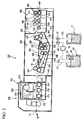
- Fig. 1 is a view schematically showing a configuration of a development device which is preferably used in the method for producing a lithographic printing plate according to the invention.
- the development device is preferably used in the case of conducting the development processing in two steps.
- the development device 1 conducts development of a lithographic printing plate precursor 10 which has been previously exposed to light in its image-recording area while transporting the exposed lithographic printing plate precursor 10 along a transport path, thereby producing a lithographic printing plate.
- the development device 1 equips a pre-heat unit 150, a first processing unit 2, a second processing unit 3, a third processing unit 4 and a drying unit 152 in this order from the upstream side in the transporting direction of the lithographic printing plate precursor 10 transported.
- the pre-heat unit 150 has a heating unit.
- the pre-heat unit 150 conducts pre-heating of the lithographic printing plate precursor 10 by the heating unit prior to the development processing.
- the pre-heat is carried out under conditions of 100°C for 10 seconds.
- the heating time and heating temperature can be appropriately changed depending on the lithographic printing plate precursor.
- the heating time is preferably set from 5 to 30 seconds.
- the heating temperature is preferably set from 60 to 140°C, and more preferably from 80 to 120°C.
- the pre-heat unit is not necessarily provided and the pre-heat unit may be omitted depending on the configuration of the lithographic printing plate precursor.
- the first processing unit 2 has a tank 20. In the tank 20, a specified amount of developer L1 is held. The first processing unit 2 develops the exposed area of the image-recording layer by immersing the lithographic printing plate precursor 10 transported in the developer L1. In the configuration shown in Fig. 1 , the first processing unit 2 functions as a first developing unit.
- the first processing unit 2 also equips a transport roller pair 22 and a transport roller pair 24.
- the transport roller pair 22 is disposed on the upstream side of the transport path in the first processing unit 2, and carries the lithographic printing plate precursor 10 transported in the developer L1 held in the tank 20 so as to be immersed.
- the transport roller pair 24 is disposed on the downstream side of the transport path in the first processing unit 2, and carries the lithographic printing plate precursor 10 out from the first processing unit 2.
- the first processing unit 2 equips a rubbing member 26.
- the rubbing member 26 is disposed between the transport roller pair 22 and the transport roller pair 24 of the transport path in the first processing unit 2.
- the rubbing member 26 rubs a surface of the lithographic printing plate precursor immersed in the developer L1 held in the tank 20 to remove the protective layer and the unexposed area of the image-recording layer. Since the rubbing member 26 rubs the lithographic printing plate precursor 10 in the state of immersion in the developer L1, scatter of the developer hardly occurs. Thus, contamination in the inside of the development device and generation of the scum caused by the scatter of developer can be avoided.
- the rubbing member may be any member capable of rubbing the surface of the lithographic printing plate precursor.
- a rotating brush roller capable of rotating around its rotation axis as the center thereof to rub the surface is preferably used.
- a rotating brush roller for example, a known channel brush, twisted brush, planted brush, carpet brush or Moulton roller can be preferably used.
- the rubbing member is immersed in the processing solution preferably to a degree of 1/3 or more of the diameter thereof, more preferably to a degree of 2/3 or more thereof, still more preferably to a degree of 3/4 or more thereof, from the standpoint of avoiding the scatter of solution.
- channel brush brushes produced by spirally winding a long so-called channel brush (strip brush) around a surface of a roller body as described in JP-UM-A-62-167253 , JP-UM-A-4-63447 , JP-UM-A-4-64128 and JP-A-6-186751 are used.
- twisted brush brushes produced by inserting a twisted brush into a spiral groove formed on the surface of a shaft thereby spirally winding it around the shaft as described in JP-A-3-87832 are used.
- planted brush brushes produced according to a method of planting a brush material in small holes formed in a shaft roller are used.
- brushes produced by winding a long and thin strip of textile woven with wool material around a peripheral surface of a shaft roller as described in JP-A-2001-5193 and JP-A-2001-66788 are used.
- brushes produced by covering a roller body with a sliding sleeve of a woven fibrous material and firmly tightening the sleeve on the mounted side thereof as described in JP-A-10-198044 are used.
- the number of revolution of the rubbing member is preferably as large as possible for improving the removability of the image-recording layer in the unexposed area of the lithographic printing plate precursor.
- it is preferably from 30 to 1,000 rpm, and more preferably from 50 to 500 rpm.
- a number of the brushes is at least one, and a plurality of brushes may also be used.
- one or more thereof may be rotated in the direction opposite to the processing direction of the lithographic printing plate precursor.
- the development processing may be performed while the rubbing member is rocked in the rotary axis direction.
- the artificial fiber usable include a polyamide, for example, nylon 6, nylon 6 ⁇ 6, nylon 6 ⁇ 10, nylon 6 ⁇ 12 or nylon 12, a polyester, for example, polyethylene terephthalate or polybutylene terephthalate (PBT), a polyacrylic, for example, polyacrylonitrile or alkyl poly(meth)acrylate, a polyolefin, for example, polyethylene, polypropylene, polystyrene, polyvinyl chloride or polyvinylidene chloride, a cellulose, for example, acetyl cellulose, a polyurethane, for example, polyurethane, polyphenylene sulfide and a fluorine resin, for example, an ethylene/tetrafluoroethylene copolymer or polyviny
- nylon 6, nylon 6 ⁇ 6, nylon 6 ⁇ 10, nylon 6 ⁇ 12, nylon 12, polypropylene, polybutylene terephthalate and polyethylene terephthalate are preferred, and nylon 6 ⁇ 6, nylon 6 ⁇ 10, nylon 6 ⁇ 12, nylon 12, polybutylene terephthalate (PBT) and polypropylene are more preferred.
- polyesters polybutylene terephthalate (PBT) is particularly preferred.
- polyolefins polypropylene is particularly preferred.
- a size of the bristle of the brush is not particularly restricted and is preferably from 0.01 to 1.0 mm, and more preferably from 0.1 to 0.5 mm.
- the rubbing property may become poor and when it is larger than 1.0 mm, rubbing scratches may be formed on the surface of the plate.
- a length of the bristle of the brush is also not particularly restricted and is ordinarily in a range from 3 to 50 mm. When the length is shorter than 3 mm, the touch of the brush to the lithographic printing plate precursor may become uneven to be apt to form rubbing scratches on the surface of the plate. When it is longer than 50 mm, it does not give any more advantage of development processing and it is economically disadvantageous.
- the Moulton roller since it is covered by a roller body with a sliding sleeve of a woven fibrous material, it is not necessary to define the size and the length of the bristle material thereof.
- the second processing unit 3 has a tank 30. In the tank 30, a specified amount of developer L2 is held. In the configuration shown in Fig. 1 , the second processing unit 3 functions as a second developing unit.
- the second processing unit 3 also equips a transport roller pair 32 and a transport roller pair 34.
- the transport roller pair 32 is disposed on the upstream side of the transport path in the second processing unit 3, and carries the lithographic printing plate precursor 10 carried out from the first processing unit 2 in the second processing unit 3.
- the transport roller pair 34 is disposed on the downstream side of the transport path in the second processing unit 3, and carries the lithographic printing plate precursor 10 out from the second processing unit 3.
- the lithographic printing plate precursor 10 is transported almost horizontally between the transport roller pair 32 and the transport roller pair 34.
- the second processing unit 3 further has a pair of spray pipes 31 disposed in parallel each other.
- the pair of spray pipes 31 is disposed so as to tuck the transport path between the both of the spray pipes. Also, the pair of spray pipes 31 is disposed between the transport roller pair 32 and the transport roller pair 34 in the transport path in the second processing unit 3.
- the pair of spray pipes 31 sprays the developer L2 on the lithographic printing plate precursor 10 transported.
- the second processing unit 3 makes it possible to develop supplementally the exposed area of the image-recording layer which remains without development in the first processing unit 2 and to wash off the scum adhered on the lithographic printing plate precursor 10.
- the second processing unit 3 equips a mechanism for feeding the developer L2 held in the tank 30 to the spray pipes 31, and the developer L2 sprayed from the spray pipes 31 returns to the tank 30, thereby conducting circulation.
- the third processing unit 4 has a tank 40. In the tank 40, a specified amount of developer L3 is held. In the configuration shown in Fig. 1 , the third processing unit 4 functions as a developing unit same as the second developing unit 3.
- the third processing unit 4 also equips a transport roller pair 42 and a transport roller pair 44.
- the transport roller pair 42 is disposed on the upstream side of the transport path in the third processing unit 4, and carries the lithographic printing plate precursor 10 carried out from the second processing unit 3 in the third processing unit 4.
- the transport roller pair 44 is disposed on the downstream side of the transport path in the third processing unit 4, and carries the lithographic printing plate precursor 10 out from the third processing unit 4.
- the lithographic printing plate precursor 10 is transported almost horizontally between the transport roller pair 42 and the transport roller pair 44.
- the third processing unit 4 further has a pair of spray pipes 41 disposed in parallel each other.
- the pair of spray pipes 41 is disposed so as to tuck the transport path between the both of the spray pipes. Also, the pair of spray pipes 41 is disposed between the transport roller pair 42 and the transport roller pair 44 in the transport path in the third processing unit 4.
- the pair of spray pipes 41 sprays the developer L3 on the lithographic printing plate precursor 10 transported.
- the third processing unit 4 makes it possible to develop supplementally the exposed area of the image-recording layer which remains without development in the first processing unit 2 and the second processing unit 3 and to wash off the scum adhered on the lithographic printing plate precursor 10.
- the third processing unit 4 equips a mechanism for feeding the developer L3 held in the tank 40 to the spray pipes 41, and the developer L3 sprayed from the spray pipes 41 returns to the tank 40, thereby conducting circulation.
- the drying unit 152 dries the lithographic printing plate precursor 10 carried out from the third processing unit 4.
- the drying temperature (temperature on the surface of the lithographic printing plate precursor) is about 55°C, and is preferably set in a range from 50 to 60°C. The temperature can be appropriately set depending on the configuration of the lithographic printing plate precursor and the formulation of the developer.
- the development device 1 also equips a replenishment unit 60 and a liquid feeding apparatus.
- the replenishment unit 60 replenishes a fresh developer to the tank 30 of the second processing unit 3 through a pipe or the like.
- the fresh developer means an unused developer which is not used for processing the lithographic printing plate precursor and is preferably an unused developer L2.
- the liquid feeding apparatus feeds a developer in an amount corresponding to the state of the developer L1 held in the tank 20 of the first processing unit 2 from the tank 30 of the second processing unit 3 to the tank 20.
- the liquid feeding apparatus equips a pipe 80, a recovery unit 82, a tank 84 and a pump 86.
- the pipe 80 is extended between the tank 20 and the tank 30, and is a closed path for running the developer L2 fed.
- the recovery unit 82 recovers the developer L2 in an amount corresponding to the amount overflowed from a recovery aperture to introduce into the pipe 80, when the developer L2 held in the tank 30 exceeds a definite liquid surface level.
- the tank 84 is connected to the recovery unit 82 through the pipe 80.
- the tank 84 temporarily retains the developer L2 recovered by the recovery unit 82.
- the pump 86 is connected to the tank 84 through the pipe 80.
- the pump 86 feeds the developer L2 retained in the tank 84 to the tank 20 of the first processing unit 2 through the pipe 80.
- the pump 86 feeds the developer L2 to the tank 20 in a feed amount corresponding to a rotation number by controlling the rotation number of a driving motor.
- the pump 86 is, for example, a pump capable of supplying a predetermined volume of the developer, and a bellows pump, a diaphragm pump, a piston pup, a plunger pump or the like is adopted.
- a filter unit for removing a foreign substance, for example, scum included in the developer L2 may be provided in the pipe.
- the scum or the like is removed from the developer and the developer can be constantly maintained in the clean state.
- the recovery unit 82 and the tank 84 may be integrally provided.
- the development device 1 can replenishes a fresh developer L2 to the tank 30 of the second processing unit 3 by the replenishment unit 60. Thus, deterioration of the state of the developer L2 held in the tank 30 can be prevented.
- the development device 1 replenishes the developer L2 from tank 30 to tank 20 by the liquid feeding apparatus depending on the state of the developer held in the first tank.
- the state of the developer held in the first tank means a height of liquid surface (level of liquid) of the developer L1 and a fatigue degree of the developer L1.
- the developer L1, the developer L2 and the developer L3 may have the same composition or different compositions as long as the effect of the invention is not impaired. It is preferred that the developer L1 is same as the developer L2.
- the development device 1 controls an amount of the developer L2 fed to the tank 20 by the liquid feeding apparatus so as not to change and to stabilize the component of the developer L1 held in the tank 20 of the first processing unit 2.
- the temperatures of the developers L1 and L2 are appropriately set respectively and are preferably from 10 to 50°C.
- a concentrated solution may be used as the developer L2 which is replenished to the tank 30 of the second processing unit 3.
- the replenishment of the concentrated solution is carried out in a case where the tank 84 is shielded and an evaporation amount is small.
- the replenishment amount in the case is preferably from 1.05 to 6 times, more preferably from 1.1 to 3 times, and still more preferably from 1.1 to 2 times.
- a solution for replenishment may be formed by dilution.
- a dilution rate is preferably from 0.6 to 0.95 times, more preferably from 0.7 to 0.9 times, and still more preferably from 0.8 to 0.9 times.
- the liquid feeding amount from the tank 30 to the tank 20 is preferably controlled to one L/min or below, in order to prevent the uniformity of temperature is locally impaired, when the liquid feeding amount is increased.
- the tank 30 maintains the uniformity of the developer L1 by means of conducting circulation of the developer L1 held by equipping a spray for circulating solution (not shown) to the tank 30 and using a circulation pump (not shown).
- the development device 1 has a liquid feeding system in which an amount of the developer corresponding to the amount increased by the replenishment by the replenishment unit 60 is recovered by the recovery unit 82, held in the tank 84 and then fed.
- the liquid feeding method is not limited thereto. An amount of developer which is preliminarily set in prospect of change in the state of the developer L1 held in the tank 20 may be fed.
- the development device 1 According to the development device 1, deterioration of the developer L2 held in the tank 30 can be prevented by performing the replenishment to the second processing unit 3 by the replenishment unit 60. Also, the developer L2 can be fed from the tank 30 to the tank 20 by the liquid feeding apparatus. Therefore, it is not necessary to provide a mechanism for replenishing the developer to the tank 20, only a predetermined amount in accordance with the state of the developer L1 can be fed to the tank 20, and an amount of liquid feeding can be accurately controlled by the pump 86. Thus, the state of the developer can be maintained to produce stably a lithographic printing plate of a high quality.
- the development device 1 feeds the developer L2 to the tank 20 through the pipe 80 which is a closed path, it can prevent the developer L2 fed from being altered upon influence, for example, evaporation.
- the developer held in the tank is allowed to overflow and the developer is supplied to the tank, it is impossible to control the amount of the developer fed and the alteration of the developer is noticeable.
- the development device 1 is capable of performing the liquid feeding even when other processing unit is present between the first processing unit 2 and the second processing unit 3.
- the configuration of the development device 1 described above is capable of being appropriately changed.
- the second processing unit and the third processing unit are formed by the horizontal transport system, the effect can be exhibited by an immersion system.
- the development device has the configuration provided with three tanks 20, 30 and 40, it is not limited thereto.
- the development device may be provided with four or more tanks.
- any of a system in which a developer held in a tank is pumped up and sprayed from a nozzle to process and a so-called disposable processing system wherein only a necessary amount of a processing solution substantially not used is supplied to each plate to conduct development can be ordinarily used. From the standpoint of avoiding the scatter of solution, a system in which the lithographic printing plate precursor is subjected to the development processing with immersion transport is excellent.
- the development device may further be provided integrally with an exposure device.
- Fig. 2 is a view schematically showing the configuration of another automatic development processor preferably used in the method for producing a lithographic printing plate according to the invention.
- the automatic development processor is preferably used in the case of conducting the development processing in one step.
- An automatic development processor 100 shown in Fig. 2 comprises a chamber the outer shape of which is formed by a machine casing 202 and has a pre-heating (pre-heat) unit 200, a developing unit 300 and a drying unit 400 continuously formed along a transporting direction (arrow A) of a transporting pass 11 for a lithographic printing plate precursor.
- pre-heat pre-heating
- developing unit 300 developing unit
- drying unit 400 continuously formed along a transporting direction (arrow A) of a transporting pass 11 for a lithographic printing plate precursor.
- the pre-heating unit 200 comprises a heating chamber 208 having a transporting inlet 212 and a transporting outlet 218 and a skewer roller 210, a heater 214 and a circulation fan 216 are arranged in the inside thereof.
- the developing unit 300 is separated from the pre-heating unit 200 by an outer panel 310 and a slit type insertion slot 312 is formed in the outer panel 310.
- a processing tank 306 having a developing tank 308 filled with a developer and an insertion roller pair 304 for guiding the lithographic printing plate precursor into the inside of the processing tank 306 are disposed.
- a shielding cover 324 is located above the developing tank 308.
- a guide roller 344 and a guide member 342 In the inside of the developing tank 308, a guide roller 344 and a guide member 342, a submerged roller pair 316, a brush roller pair 322, a brush roller pair 326 and a carrying-out roller pair 318 are provided in order from the upstream side of the transporting direction of lithographic printing plate precursor.
- the lithographic printing plate precursor transported into the developing tank 308 is immersed in the developer and the non-image area is removed by passing between the rotating brush roller pairs 322 and 326.
- a spray pipe 330 is provided under the brush roller pairs 322 and 326.
- the spray pipe 330 is connected to a pump (not shown) and the developer in the developing tank 308 sucked by the pump is ejected from the spray pipe 330 in the developing tank 308.
- an overflow aperture 51 is provided to form a top edge of a first circulation pipeline C1.
- the excess developer flows in the overflow aperture 51, passes through the first circulation pipeline C1 and is discharged in an external tank 50 provided outside the developing unit 300.
- a second circulation pipeline C2 and a filter unit 54 and a developer supply pump 55 are located in the second circulation pipeline C2.
- the developer is supplied from external tank 50 to the developing tank 308 by the developer supply pump 55.
- an upper limit liquid level meter 52 and a lower limit liquid level meter 53 are provided in the external tank 50.
- the developing tank 308 is also connected to a water tank for replenishment 71 through a third circulation pipeline C3.
- a water-replenishing pump 72 is located in the third circulation pipeline C3 and water pooled in the water tank for replenishment 71 is supplied to the developing bath 308 by the water-replenishing pump 72.
- a liquid temperature sensor 336 is provided on the upstream side of the submerged roller pair 316.
- a liquid level meter 338 is provided on the upstream side of the canying-out roller pair 318.
- a slit type pass-through slot 334 is formed in a partition board 332 placed between the developing unit 300 and the drying unit 400. Also, a shutter (not shown) is provided along a passage between the developing unit 300 and the drying unit 400 and the passage is closed by the shutter when the lithographic printing plate precursor 11 does not pass through the passage.
- a support roller 402 ducts 410 and 412, a transport roller pair 406, ducts 410 and 412 and a transport roller pair 408 are disposed in this order.
- a slit hole 414 is provided at the top of each of the ducts 410 and 412.
- a drying means (not shown), for example, a hot air supplying means or a heat generating means, is also provided.
- the drying unit 400 has a discharge slot 404 and the resulting lithographic printing plate dried by the drying means is discharged through the discharge slot 404.
- a developer having the composition shown below can be preferably used.
- a developer containing at least any of a surfactant and a water-soluble polymer compound described hereinafter is preferred in view of imparting the oil-desensitizing treatment ability.
- the developer for use in the method for producing a lithographic printing plate according to the invention is preferably an aqueous solution containing water as the main component (containing 60% by weight or more of water).
- the pH of the developer is preferably from 2.0 to 10.0, more preferably from 5.0 to 10.0, still more preferably from 6.0 to 10.0, and most preferably from 6.5 to 9.9.
- the developer may contain an alkali agent.
- the pH thereof is preferably in a range from 8.0 to 10.0, more preferably from 9.0 to 10.0, and still more preferably from 9.2 to 9.9.
- the pH thereof is preferably in a range from 2.0 to 9.0, more preferably from 4.0 to 8.0, and still more preferably from 4.5 to 7.5.
- the developer for use in the invention preferably contains a surfactant
- the surfactant used includes, for example, anionic, cationic, nonionic or amphoteric surfactant.
- the anionic surfactant described above is not particularly restricted and includes, for example, fatty acid salts, abietic acid salts, hydroxyalkanesulfonic acid salts, alkanesulfonic acid salts, dialkylsulfosuccinic acid salts, straight-chain alkylbenzenesulfonic acid salts, branched alkylbenzenesulfonic acid salts, alkylnaphthalenesulfonic acid salts, alkyldiphenylether (di)sulfonic acid salts, alkylphenoxy polyoxyethylene propylsulfonic acid salts, polyoxyethylene alkylsulfophenyl ether salts, N-methyl-N-oleyltaurine sodium salt, N-alkylsulfosuccinic acid monoamide disodium salts, petroleum sulfonic acid salts, sulfated castor oil, sulfated beef tallow oil, sulfate ester sl
- the cationic surfactant described above is not particularly restricted and includes, for example, alkylamine salts, quaternary ammonium salts, polyoxyethylene alkyl amine salts and polyethylene polyamine derivatives.
- the nonionic surfactant described above is not particularly restricted and includes, for example, polyethylene glycol type higher alcohol ethylene oxide adducts, alkylphenol ethylene oxide adducts, alkylnaphthol ethylene oxide adducts, phenol ethylene oxide adducts, naphthol ethylene oxide adducts, fatty acid ethylene oxide adducts, polyhydric alcohol fatty acid ester ethylene oxide adducts, higher alkylamine ethylene oxide adducts, fatty acid amide ethylene oxide adducts, ethylene oxide addacts of fat, polypropylene glycol ethylene oxide adducts, dimethylsiloxane-ethylene oxide block copolymers, dimethylsiloxane-(propylene oxide-ethylene oxide) block copolymers, fatty acid esters of polyhydric alcohol type glycerol, fatty acid esters of pentaerythritol, fatty acid esters of sorbito
- those having an alkylene oxide chain are preferred, those having an aromatic ring and an ethylene oxide chain are more preferred, and alkyl-substituted or unsubstituted phenol ethylene oxide adducts and alkyl-substituted or unsubstituted naphthol ethylene oxide adducts are still more preferred.
- nonionic surfactant having an alkylene oxide chain a nonionic aromatic ether surfactant represented by formula (3) shown below is particularly preferably exemplified.
- X represents an aromatic group
- Y represents single bond or an alkylene group having from 1 to 10 carbon atoms
- a and B which are different from each other, each represents -CH 2 CH 2 O- or -CH 2 CH(CH 3 )O-
- n and m each represents an integer from 0 to 100, provided that a sum of n and m is 2 or more.
- the aromatic group represented by X includes a phenyl group, a naphthyl group or an anthryl group.
- the aromatic group may have a substituent.
- the substituent includes an organic group having from 1 to 100 carbon atoms. Examples of the organic group are same as examples of the organic group described for formulae (3-A) and (3-B) shown below.
- formula (3) when both A and B are present, they may be present at random or as a block.
- n and m is preferably from 4 to 100, more preferably from 6 to 50, still more preferably from 8 to 30, and particularly preferably from 10 to 28.
- nonionic aromatic ether surfactants represented by formula (3) compounds represented by formula (3-A) or (3-B) shown below are preferred.
- R 10 and R 20 each represents a hydrogen atom or an organic group having from 1 to 100 carbon atoms
- t and u each represents 1 or 2
- Y 1 and Y 2 each represents a single bond or an alkylene group having from 1 to 10 carbon atoms
- v and w each represents an integer from 0 to 100, provided that a sum of v and w is 2 or more
- v' and w' each represents an integer from 0 to 100, provided that a sum of v' and w' is 2 or more.
- R 10 represents an organic group having from 1 to 100 carbon atoms
- two R 10 may be the same or different, or may be combined with each other to from a ring.
- R 20 represents an organic group having from 1 to 100 carbon atoms
- two R 20 may be the same or different, or may be combined with each other to from a ring.
- organic group having from 1 to 100 carbon atoms include a saturated or unsaturated, straight-chain or branched aliphatic hydrocarbon group or an aromatic hydrocarbon group (for example, an alkyl group, an alkenyl group, an alkynyl group, an aryl group or an aralkyl group), an alkoxy group, an aryloxy group, an N-alkylamino group, an N,N-dialkylamino group, an N-arylamino group, an N,N-diarylamino group, an N-alkyl-N-arylamino group, an acyloxy group, a carbamoyloxy group, an N-allcylcarbamoyloxy group, an N-arylcarbamoyloxy group, an N,N-dialkylcarbamoyloxy group, an N,N-diarylcarbamoyloxy group, an N-allcyl-N-arylcarbamoyloxy group,
- R 10 or R 20 include a hydrogen atom, a straight-chain or branched alkyl group having from 1 to 10 carbon atoms, an alkoxy group having from 1 to 10 carbon atoms, an alkoxycarbonyl group, an N-alkylamino group, an N,N-dialkylamino group, an N-alkylcarbamoyl group, an acyloxy group, an acylamino group, a polyoxyalkylene chain having a repeating unit number from about 5 to about 20, an aryl group having from 6 to 20 carbon atoms and an aryl group having a polyoxyalkylene chain having a repeating unit number from about 5 to about 20.
- a repeating unit number of the polyoxyethylene chain is preferably from 3 to 50, and more preferably from 5 to 30.
- a repeating unit number of the polyoxypropylene chain is preferably from 0 to 10, and more preferably from 0 to 5.
- the polyoxyethylene part and polyoxypropylene part may be present at random or as a block.
- nonionic aromatic ether surfactant represented by formula (3) Specific examples of the nonionic aromatic ether surfactant represented by formula (3) are set forth below, but the invention should not be construed as being limited thereto.
- amphoteric surfactant described above is not particularly restricted and includes, for example, an amine oxide type, for example, an alkyldimethylamine oxide, a betaine type, for example, an alkyl betaine, and an amino acid type, for example, sodium salt of alkylamino fatty acid.
- an amine oxide type for example, an alkyldimethylamine oxide
- a betaine type for example, an alkyl betaine
- an amino acid type for example, sodium salt of alkylamino fatty acid.
- an alkyldimethylamine oxide which may have a substituent an alkyl carboxyl betaine which may have a substituent and an alkyl sulfo betaine which may have a substituent are preferably used.
- Specific examples thereof include compounds described, for example, in Paragraph Nos. [0255] to [0278] of JP-A-2008-203359 and Paragraph Nos. [0028] to [0052] of JP-A-2008-276166 .
- amphoteric surfactant used in the developer a compound represented by formula (1) shown below or a compound represented by formula (2) shown below is preferred.
- R 1 and R 11 each independently represents an alkyl group having from 8 to 20 carbon atoms or an alkyl group having from 8 to 20 carbon atoms in total and a connecting group.
- R 2 , R 3 , R 12 and R 13 each independently represents a hydrogen atom, an alkyl group or a group containing an ethyleneoxide group.
- R 4 and R 14 each independently represents a single bond or an alkylene group.
- two groups represented by R 1 , R 2 , R 3 and R 4 may be combined with each other to form a ring structure
- two groups represented by R 11 , R 12 , R 13 and R 14 may be combined with each other to form a ring structure.
- the hydrophobic portion becomes larger and solubility of the compound in the aqueous developer decreases.
- the solubility is improved by mixing with water, as a dissolution auxiliary agent, an organic solvent for assisting the dissolution, for example, an alcohol.
- an organic solvent for assisting the dissolution for example, an alcohol.
- the sum of carbon atoms in R 1 to R 4 or R 11 to R 14 is preferably from 10 to 40, and more preferably from 12 to 30.
- the alkyl group having a connecting group represented by R 1 or R 11 indicates a structure having a connecting group in the alkyl group.
- the connecting group is one
- the alkyl group is represented by "-alkylene group-connecting group-alkyl group".
- the connecting group includes an ester bond, a carbonyl bond and an amido bond.
- the connecting groups may present two or more, one connecting group is preferred and an amido bond is particularly preferred.
- the total number of carbon atoms in the alkylene group bonding to the connecting group is preferably from 1 to 5.
- the alkylene group may be straight-chain or branched, it is preferably a straight-chain alkylene group.
- the alkyl group bonding to the connecting group preferably has from 3 to 19 carbon atoms and although it may be straight-chain or branched, it is preferably a straight-chain alkyl group.
- R 2 or R 12 represents an alkyl group
- the total number of carbon atoms is preferably from 1 to 5, and particularly preferably from 1 to 3.
- the alkyl group may be straight-chain or branched, it is preferably a straight-chain alkyl group.
- R 3 or R 13 represents an alkyl group
- the total number of carbon atoms is preferably from 1 to 5, and particularly preferably from 1 to 3.
- the alkyl group may be straight-chain or branched, it is preferably a straight-chain alkyl group.
- the group containing an ethyleneoxide group represented by R 3 or R 13 includes a group represented by -Ra(CH 2 CH 2 O) n Rb, wherein Ra represents a single bond, an oxygen atom or a divalent organic group (preferably having 10 or less carbon atoms), Rb represents a hydrogen atom or an organic group (preferably having 10 or less carbon atoms), and n represents an integer from 1 to 10.
- R 4 or R 14 represents an alkylene group
- the total number of carbon atoms is preferably from 1 to 5, and particularly preferably from 1 to 3.
- the alkylene group may be straight-chain or branched, it is preferably a straight-chain alkylene group.
- the compound represented by formula (1) or the compound represented by formula (2) preferably has an amido bond and more preferably has an amido bond as the connecting group in R 1 or R 11 .
- the compound represented by formula (1) or (2) can be synthesized according to a known method. Also, it is possible to use a commercial product.
- a commercial product for the compound represented by formula (1) for example, SOFTAZOLINE LPB, SOFTAZOLINE LPB-R or VISTA MAP produced by Kawaken Fine Chemicals Co., Ltd. and TAKESURF C-157L produced by Takemoto Oil & Fat Co., Ltd. are exemplified.
- As the commercial product for the compound represented by formula (2) for example, SOFTAZOLINE LAO produced by Kawaken Fine Chemicals Co, Ltd. and AMOGEN AOL produced by Dai-Ichi Kogyo Seiyaku Co., Ltd. are exemplified.
- Two or more kinds of the surfactants may be used.
- at least one of the surfactants is a nonionic surfactant.
- a combination of a nonionic surfactant and a nonionic surfactant or a combination of an amphoteric surfactant and a nonionic surfactant is more preferred.
- the content of the surfactant in the developer is preferably from 0.01 to 20% by weight, and more preferably from 0.1 to 10% by weight.
- a water-soluble polymer compound having a film-forming property for the purpose of assisting oil-desensitization of the non-image area and plate surface protecting property.
- water-soluble polymer compound for example, gum arabic, a cellulose derivative (for example, carboxymethyl cellulose, carboxyethyl cellulose, methyl cellulose, hydroxypropyl cellulose or methyl propyl cellulose) or a modified product thereof, polyvinyl alcohol or a derivative thereof, polyvinyl pyrrolidone, polyacrylamide, a vinyl methyl ether/maleic anhydride copolymer, a vinyl acetate/maleic anhydride copolymer, a styrene/maleic anhydride copolymer, a starch derivative (for example, dextrin, maltodextrin, enzyme-decomposed dextrin, hydroxypropylated starch, hydroxypropylated starch enzyme-decomposed dextrin, carboxymethylated starch, phosphorylated starch or cyclodextrin), and pllulan or a derivative thereof are exemplified.
- a starch derivative for example, dex
- starch derivative which can be used as the water-soluble polymer compound, for instance, roast starch, for example, British gum, an enzymatically modified dextrin, for example, enzyme dextrin or Shardinger dextrin, oxidized starch, for example, solubilized starch, alphalized starch, for example, modified alphalized starch or unmodified alphalized starch, esterified starch, for example, starch phosphate, starch of fatty acid, starch sulfate, starch nitrate, starch xanthate or starch carbamate, etherified starch, for example, carboxyalkyl starch, hydroxyalkyl starch, sulfoalkyl starch, cyanoethyl starch, allyl starch, benzyl starch, carbamylethyl starch or dialkylamino starch, crosslinked starch, for example, methylol crosslinked starch, hydroxyalkyl crosslinked starch,
- a natural polymer compound which can be used as the water-soluble polymer compound includes, for example, a water-soluble soybean polysaccharide, a starch, for example, starch, gelatin, hemicellulose extracted from soybean, sweet potato starch, potato starch, tapioca starch, wheat starch or corn starch, a polymer obtained from seaweed, for example, carrageenan, laminaran, seaweed mannan, funori, Irish moss, agar or sodium alginate, plant mucilage, for example, of tororoaoi, mannan, quince seed, pectin, tragacanth gum, karaya gum, xanthine gum, guar bean gum, locust bean gum, carob gum or benzoin gum, bacteria mucilage, for example, of homopolysaccharide, e.g., dextran, glucan or levan or of heteropolysaccharide, e.g., succinoglucan or x
- gum arabic for example, gum arabic, a starch derivative, for example, dextrin or hydroxypropyl starch, carboxymethyl cellulose or soybean polysaccharide can be preferably used.
- the content of the water-soluble polymer compound in the developer is preferably from 0.05 to 15% by weight, and more preferably from 0.5 to 10% by weight.
- the developer for use in the invention preferably further contains a pH buffer agent.
- a buffer agent exhibiting a buffer function in a pH range from 2.0 to 10.0 is preferably used and a pH buffer agent functioning in a weak alkaline range is more preferably used.
- a carbonate ion and a hydrogen carbonate ion is preferably used.
- a borate ion is exemplified.
- a combination of a carbonate ion and a hydrogen carbonate ion, (b) a borate ion, or (c) a combination of an organic amine compound and an ion of the organic amine compound exhibits a pH buffer function in the developer to prevent fluctuation of the pH even when the developer is used for a long period of time.
- a carbonate ion and a hydrogen carbonate ion or the combination (c) of an organic amine compound and an ion of the organic amine compound is particularly preferred.
- a carbonate and a hydrogen carbonate may be added to the developer or a carbonate ion and a hydrogen carbonate ion may be generated by adding a carbonate or a hydrogen carbonate to the developer and then adjusting the pH.
- the carbonate or hydrogen carbonate used is not particularly restricted and it is preferably an alkali metal salt thereof. Examples of the alkali metal include lithium, sodium and potassium and sodium is particularly preferred. The alkali metals may be used individually or in combination of two or more thereof.
- the total amount of the carbonate ion and hydrogen carbonate ion is preferably from 0.05 to 5 mole/l, more preferably from 0.1 to 2 mole/l, particularly preferably from 0.2 to 1 mole/l, in the developer.
- the total amount is 0.05 mole/l or more, the development property and processing ability are hardly degraded.
- the total amount is 5 mole/l or less, precipitates and crystals hardly generate and since gelation at neutralization of waste liquid of the developer hardly occur, treatment of the waste liquid can be carried out without trouble.
- the total amount of the borate ion is preferably from 0.05 to 5 mole/l, more preferably from 0.1 to 2 mole/l, particularly preferably from 0.2 to 1 mole/l, in the developer.
- the amount of the borate is 0.05 mole/l or more, the development property and processing ability are hardly degraded.
- the amount of the borate is 5 mole/l or less, precipitates and crystals hardly generate and since gelation at neutralization of waste liquid of the developer hardly occur, treatment of the waste liquid can be carried out without trouble.
- a combination of a water-soluble amine compound and an ion of the amine compound is also preferably used.
- the water-soluble amine compound is not particularly restricted and preferably a water-soluble amine having a group capable of facilitating water solubility.
- the group capable of facilitating water solubility includes, for example, a carboxylic acid group, a sulfonic acid group, a sulfinic acid group, a phosphonic acid group and a hydroxy group.
- the water-soluble amine compound may have two or more groups capable of facilitating water solubility.
- the carboxylic acid group, sulfonic acid group, sulfinic acid group or phosphonic acid group may form a salt structure.
- an amine compound having a hydroxy group is particularly preferred.
- the water-soluble amine compound having a carboxylic acid group, a sulfonic acid group or a sulfinic acid group include an amino acid, for example, glycine, aminodiacatic acid, lysine, threonine, serine, asparaginic acid, parahydroxyphenyl glycine, dihydroxyethyl glycine, alanine, anthranilic acid or tryptophan, sulfamic acid, cyclohexylsulfamic acid, a fatty acid amine sulfonic acid, for example, taurine, a fatty acid amine sulfinic acid, for example, aminoethanesulfinic acid, and a sodium salt, potassium salt or ammonium salt thereof.
- glycine, aminodiacetic acid and the salts thereof are preferred.
- water-soluble amine compound having a phosphonic acid group examples include 2-aminoethylphosphonic acid, 1-aminoethane-1,1-diphosphonic acid, 1-amino-1-phenylmethane-1,1-diphosphonic acid, 1-dimethylaminoethane-1,1-diphosphonic acid, ethylenediaminopentamethylenephosphonic acid, and a sodium salt, potassium salt or ammonium salt thereof.
- 2-aminoethylphosphonic acid or a salt thereof is preferred.
- water-soluble amine compound having a hydroxy group examples include monoethanol amine, diethanol amine, triethanol amine, N-hydroxyethylmorpholine, monoisopropanol amine, monoisopropanol amine, diisopropanol amine, diisoprppanol amine, triisopropanol amine, triisopropanol amine and N,N-diethanolaniline.
- monoethanol amine, diethanol amine, triethanol amine or N-hydroxyethylmorpholine is preferred.
- a di- or tri-alkanolamine compound which is substituted with an alkyl group having at least one hydroxy group and an ion thereof are particularly preferred.
- the alkyl group having at least one hydroxy group may further have a substituent selected from a hydroxy group, a halogen atom, a nitro group, a nitrile group, a (hetero)aromatic group and a saturated or unsaturated hydrocarbon group.
- the alkyl group is preferably that having 15 or less carbon atoms, more preferably that having 12 or less carbon atoms, and still more preferably that having 8 or less carbon atoms.
- alkanol group examples include HO-CH 2 -*, HO-CH 2 -CH 2 -*, HO-CH 2 -CH 2 -CH 2 -*, CH 3 -CH(OH)-CH 2 -*, CH 3 -C(OH)(CH 3 )-*, HO-CH 2 -CH 2 -CH 2 -*, CH 3 -CH(CH 3 )-CH(OH)-*, CH 3 -CH(C 2 H 5 )-CH(OH)-*, CH 3 -C(CH 3 )(OH)-CH 2 -*, HO-CH 2 -CH 2 -CH 2 -CH 2 -CH 2 -*,HO-CH 2 -CH 2 -CH 2 -CH 2 -CH 2 -*,HO-CH 2 -CH 2 -CH(OH)-CH 2 -CH 2 -*, CH 3 -CH 2 CH(OH)-CH 2 -CH 2 -CH 2 -*, CH 3
- di- or tri-alkanolamine examples include triethanolamine, diethanolamine, 2-amino-2-methyl-1,3-propanediol, 2-amino-2-ethyl-1,3-propanediol, trishydroxymethylaminomethane and triisopropanolamine.
- the ion of the water-soluble amine compound may be generated in an aqueous solution of the water-soluble amine compound.
- To the aqueous solution of the water-soluble amine compound may further be added an alkali or an acid.
- the ion of the water-soluble amine compound may be contained in an aqueous solution by adding a salt of the water-soluble amine compound.
- alkali for example, sodium hydroxide, potassium hydroxide, lithium hydroxide, sodium carbonate, potassium carbonate, ammonium carbonate, sodium hydrogen carbonate, potassium hydrogen carbonate, ammonium hydrogen carbonate, or a combination thereof
- acid for example, an inorganic acid, for example, hydrochloric acid, sulfuric acid, a nitric acid, phosphoric acid or phosphorous acid can be used, and particularly phosphoric acid or phosphorous acid is preferred.
- the pH can be finely adjusted.
- the developer according to the invention preferably contains a salt composed of a reaction product of an acid and an amine. Thus, an ion of the organic amine compound is generated.
- the developer more preferably contains a salt composed of a reaction product of at least any acid of phosphoric acid and phosphorous acid and a di- or tri-alkanolamine.
- the amount thereof is preferably from 0.005 to 5 mole/l, more preferably from 0.01 to 2 mole/l, particularly preferably from 0.01 to 1 mole/l, in terms of molar concentration in the developer.
- the total amount of the organic amine compound and ion is in the range described above, the development property and processing ability do not degrade and treatment of the waste liquid is easily carried out.
- the pH buffer agent is the salt composed of a reaction product of at least any acid of phosphoric acid and phosphorous acid and a di- or tri-alkanolamine
- the amount thereof is preferably at least 0.02 mole/l, more preferably at least 0.1 mole/l, particularly preferably at least 0.15 mole/l, and is preferably 5 mole/l or less, more preferably 2.5 mole/l or less, particularly preferably 1 mole/l or less, in terms of molar concentration in the developer.
- a substance amount ratio of the amine to the acid is preferably 0.1 or more, more preferably 0.4 or more, most preferably 0.75 or more, and is preferably 20 or less, more preferably 12 or less, still more preferably 5 or less.
- the developer according to the invention may contain an organic solvent.
- an organic solvent capable of being contained, for instance, an aliphatic hydrocarbon (for example, hexane, heptane, ISOPAR E, ISOPAR H, ISOPAR G (produced by Esso Chemical Co., Ltd.)), an aromatic hydrocarbon (for example, toluene or xylene), a halogenated hydrocarbon (methylene dichloride, ethylene dichloride, trichlene or monochlorobenzene) or a polar solvent is exemplified.
- an aliphatic hydrocarbon for example, hexane, heptane, ISOPAR E, ISOPAR H, ISOPAR G (produced by Esso Chemical Co., Ltd.
- an aromatic hydrocarbon for example, toluene or xylene
- a halogenated hydrocarbon methylene dichloride, ethylene dichloride, trichlene or monochlorobenzene
- the polar solvent examples include an alcohol (for example, methanol, ethanol, propanol, isopropanol, 1-butanol, 1-pentanol, 1-hexanol, 1-heptanol, 1-octanol, 2-octanol, 2-ethyl-1-hexanol, 1-nonanol, 1-decanol, benzyl alcohol, ethylene glycol monomethyl ether, 2-ethyoxyethanol, diethylene glycol monoethyl ether, diethylene glycol monohexyl ether, triethylene glycol monomethyl ether, propylene glycol monoethyl ether, propylene glycol monomethyl ether, polyethylene glycol monomethyl ether, polypropylene glycol, tetraethylene glycol, ethylene glycol monobutyl ether, ethylene glycol monobenzyl ether, ethylene glycol monophenyl ether, propylene glycol monophenyl ether, methyl phenyl carb
- the organic solvent contained in the developer may be used two or more kinds in combination.
- the organic solvent When the organic solvent is insoluble in water, it may be employed by being solubilized in water using a surfactant or the like.
- the concentration of the organic solvent is desirably less than 40% by weight, preferably less than 10% by weight, more preferably less than 5% by weight, in view of safety and inflammability.
- the developer according to the invention may contain an enzyme.
- the enzyme for use in the invention the kind thereof is not particularly restricted, as long as the enzyme has a function of preventing the occurrence of development scum in the development processing of a lithographic printing plate precursor having a photopolymerizable image-recording layer.
- the groups of enzymes as described in Koso Handbook, Third Edition, edited by Tatsuhiko Yagi et al, Asakura Publishing Co., Ltd. are appropriately used.
- the ethylenically unsaturated compounds are composed, for example, of a carbon atom, a hydrogen atom, a nitrogen atom, an oxygen atom, a sulfur atom, a phosphorus atom and a halogen atom in many cases, an enzyme capable of hydrolyzing a carboxylic acid ester bond, an enzyme capable of hydrolyzing a phosphoric acid ester, an enzyme capable of hydrolyzing a sulfuric acid ester, an enzyme capable of hydrolyzing an ether bond, an enzyme capable of hydrolyzing a thioether structure, an enzyme capable of hydrolyzing a peptide bond, an enzyme capable of hydrolyzing a carbon-nitrogen bond, an enzyme capable of hydrolyzing a carbon-carbon bond, an enzyme capable of hydrolyzing a carbon-halogen bond and the like are exemplified as preferred enzymes.
- the enzymes capable of hydrolyzing at least one member selected from the group consisting of an ester bond, an amido bond, a tertiary amino group, a urethane bond, a urea bond, a thiourethane bond and a thiourea bond are more preferred.
- EC3.1 ester hydrolytic enzyme
- Group EC3.4 peptide bond hydrolytic enzyme
- EC3.1.1.3 triacylglycerol lipase
- EC3.4.11.1 leucyl aminopeptidase
- EC3.4.21.62 subtilisin
- EC3.4.21.63 oryzin
- EC3.4.22.2 papain
- EC3.4.22.32 stem bromelain
- EC3.4.23.18 aspergillopepsin I
- EC3.4.24.25 vibriolysin
- EC3.4.24.27 thermolysin
- EC3.4.24.28 bacillolysin
- EC3.1.1.3 EC3.4.21.14, EC3.4.21.62 and EC3.4.21.63 are most preferred.
- the pH of the developer is preferably from 2.0 to 10.0, more preferably from 5.0 to 10.0, still more preferably from 6 to 10.0, and most preferably from 6.9 to 9.9.
- alkali enzyme as used herein means an enzyme which has an optimum pH range in an alkaline range.
- the enzyme having the optimum pH range from 6.9 to 9.9 is preferred.
- the enzyme having an optimum temperature range from 20 to 60°C is preferred, and that having an optimum temperature range from 25 to 50°C is more preferred.
- an enzyme capable of mainly hydrolyzing an ester group of the monomer under an alkali condition for example, alkali protease or alkali lipase is preferred.
- alkali protease enzymes of microbial origin, for example, Bacillus subtilis, Aspergillus oryzae, Bacillus stearothermophilus, papaya latex, papaya, Ananas comosus M, Pig pancreas, Bacillus licheniformis, Aspergillus melleus, Aspergillus sp., Bacillus lentus, Bacillus sp. and Bacillus clausii are exemplified.
- enzymes of microbial origin for example, Candida cylindracea, Humicola lanuginosa, Psudomonas, Mucor sp., Chromobacterium viscosum, Rhizopus japonics, Aspergillus niger, Mucor javanicus, Penicillium camemberti, Rhizopus oryzae, Candida rugosa, Penicillium roqueforti, Rhizopus delemar, Psendomonas sp., Aspergillus sp., Rhizomucor miehei, Bacillus sp. and Alcaligenes sp. are exemplified.
- Lipase PL Lipase QLM, Lipase SL, Lipase MY and Lipase OF (produced by Dai-Nippon Meiji Sugar Co., Ltd.), Newlase F3G, Lipase A “Amano” 6, Lipase AY “Amano” 30G, Lipase G “Amano” 50, Lipase R “Amano”, Lipase AS “Amano”, Umamizayme G, Papain W-40, Protease A “Amano” G, Protease N “Amano” G, Protease NL “Amano”, Protease P “Amano” 3G, Protease S “Amano” G, Bromelain F, Proleather FG-F, Peptidase R, Thermoase PC10F, Protin SD-AC10F, Protin SD-AY10, Protin SD-PC10F, Protin SD-NY10, Spleen digestive enzyme TA
- the enzyme may be directly incorporated into the developer or may be added to the developer at the time of processing of a lithographic printing plate precursor. Also, the development processing may be conducted while supplying the enzyme to the developer.
- the content of the enzyme used is preferably from 0.01 to 20% by weight, more preferably from 0.1 to 10% by weight, most preferably from 0.2 to 5% by weight, based on the total amount of the developer.
- the developer may contain a preservative, a chelating agent, a defoaming agent, an organic acid, an inorganic acid, an inorganic salt or the like in addition the components described above.
- a preservative e.g., a chelating agent, a defoaming agent, an organic acid, an inorganic acid, an inorganic salt or the like.
- compounds described in Paragraph Nos. [0266] to [0270] of JP-A-2007-206217 are preferably used.
- the developer according to the invention can be used as a developer for the exposed lithographic printing plate precursor and a development replenisher, if desired.
- the developer can be preferably applied to the automatic development processor described above. In the case of conducting the development processing using the automatic development processor, the developer becomes fatigued in accordance with the processing amount, and hence the processing ability may be restored using a replenisher or a fresh developer.
- the lithographic printing plate precursor may be heated its entire surface before the exposure, during the exposure or between the exposure and the development, if desired.
- the heating the image-forming reaction in the image-recording layer is accelerated and advantages, for example, improvement in the sensitivity and printing durability and stabilization of the sensitivity are achieved.
- the heating before the development is preferably performed under a mild condition of 150°C or lower.
- the temperature is too high, a problem may arise in that the unexposed area is cured.
- the heating after the development can be performed using very strong conditions and is ordinarily carried out in a temperature range from 100 to 500°C.
- the temperature is too low, a sufficient effect of strengthening the image may not be obtained, whereas when it is excessively high, problems of deterioration of the support and thermal decomposition of the image area may occur.
- An aluminum plate (material: 1050, refining: H16) having a thickness of 0.24 mm was immersed in an aqueous 5% sodium hydroxide solution maintained at 65°C to conduct a degreasing treatment for one minute, followed by washing with water.
- the aluminum plate was immersed in an aqueous 10% hydrochloric acid solution maintained at 25°C for one minute to neutralize, followed by washing with water.
- the aluminum plate was subjected to an electrolytic surface-roughening treatment with alternating current under condition of current density of 100 A/dm 2 in an aqueous 0.3% by weight hydrochloric acid solution at 25°C for 60 seconds and then subjected to a desmut treatment in an aqueous 5% sodium hydroxide solution maintained at 60°C for 10 seconds.
- the aluminum plate was subjected to an anodizing treatment under conditions of current density of 10 A/dm 2 and voltage of 15 V in an aqueous 15% sulfuric acid solution at 25°C for one minute, then subjected to a hydrophilization treatment by immersing in an aqueous 1% polyvinylphosphonic acid solution at 60°C for 10 seconds, washing at 20°C with hard water having calcium ion concentration of 75 ppm for 4 seconds and then with pure water for 4 seconds, and dried, thereby preparing Support 1.
- the adhesion amount of calcium was 2.0 mg/m 2 .
- the surface roughness of Support 1 was measured and found to be 0.44 ⁇ m (Ra indication according to JIS B 0601).
- Coating solution (1) for photosensitive layer having the composition shown below was coated on Support 1 using a bar and dried in an oven at 90°C for 60 seconds to form Photosensitive layer 1 having a dry coating amount of 1.3 g/m 2 .
- Binder Polymer (1) (weight average molecular weight: 50,000) shown below 0.04 g Binder Polymer (2) (weight average molecular weight: 80,000) shown below 0.30 g Polymerizable Compound (1) shown below 0.17 g (PLEX 6661-O, produced by Degussa Japan Co., Ltd.) Polymerizable Compound (2) shown below 0.51 g Sensitizing Dye (1) shown below 0.03 g Sensitizing Dye (2) shown below 0.015 g Sensitizing Dye (3) shown below 0.015 g Polymerization Initiator (1) shown below 0.13 g Chain transfer agent 0.01 g Mercaprobenzothiazole Dispersion of ⁇ -phthalocyanine pigment 0.40 g (pigment: 15 parts by weight; dispersing agent (allyl methacrylate/methacrylic acid copolymer (weight average molecular weight: 60,000, copolymerization molar ratio: 83/17)): 10 parts by weight; cyclohexanone: 15 parts by weight) Thermal
- Coating solutions (1) to (8) for protective layer having the composition shown below was coated on the photosensitive layer described above using a bar so as to have a dry coating amount of 1.2 g/m 2 and dried at 125°C for 70 seconds to form a protective layer, thereby preparing Lithographic printing plate precursors 1 to 8, respectively.
- Protective layer polymer shown in Table A or Table B 0.53 g PVA-205 (partially hydrolyzed polyvinyl alcohol, produced by Kuraray Co., Ltd. (saponification degree: 86.5 to 89.5% by mole, viscosity: 4.6 to 5.4 mPa ⁇ s in a 4% by weight aqueous solution at 20°C)) 0.13 g PVA-105 (fully hydrolyzed polyvinyl alcohol, produced by Kuraray Co., Ltd.
- Coating solutions (9) to (11) for protective layer having the composition shown below was coated on the photosensitive layer described above using a bar so as to have a dry coating amount of 1.2 g/m 2 and dried at 125°C for 70 seconds to form a protective layer, thereby preparing Lithographic printing plate precursors 9 to 11, respectively.
- Protective layer polymer shown in Table A or Table B 0.53 g PVA-205 (partially hydrolyzed polyvinyl alcohol, produced by Kuraray Co., Ltd. (saponification degree: 86.5 to 89.5% by mole, viscosity: 4.6 to 5.4 mPa ⁇ s in a 4% by weight aqueous solution at 20°C)) 0.13 g PVA-105 (fully hydrolyzed polyvinyl alcohol, produced by Kuraray Co., Ltd.
- An aluminum plate (material: 1050, refining: H16) having a thickness of 0.3 mm was immersed in an aqueous 10% by weight sodium hydroxide solution at 60°C for 25 seconds to effect etching, washed with running water, neutralized and cleaned with an aqueous 20% by weight nitric acid solution and then washed with water.
- the aluminum plate was subjected to an electrolytic surface roughening treatment in an aqueous 1 % by weight nitric acid solution using an alternating current with a sinusoidal waveform at an anode time electricity of 300 coulomb/dm 2 .
- the aluminum plate was immersed in an aqueous 1% by weight sodium hydroxide solution at 40°C for 5 seconds, immersed in an aqueous 30% by weight sulfuric acid solution at 60°C for 40 seconds to effect a desmut treatment, and then subjected to an anodizing treatment in an aqueous 20% by weight sulfuric acid solution for 2 minutes under condition of current density of 2 A/dm 2 to form an anodic oxide film having a thickness of 2.7 g/m 2 .
- the aluminum plate was subjected to a hydrophilization treatment by immersing in an aqueous 1% polyvinylphosphonic acid solution at 60°C for 10 seconds, washing at 20°C with hard water having calcium ion concentration of 75 ppm for 4 seconds and then with pure water for 4 seconds, and drying, thereby preparing Support 2.
- the adhesion amount of calcium was 1.8 mg/m 2 .
- the surface roughness of Support 2 was measured and found to be 0.28 ⁇ m (Ra indication according to JIS B 0601).
- Coating solution (2) for photosensitive layer having the composition shown below was coated on Support 2 using a bar and dried in an oven at 90°C for 60 seconds to form Photosensitive layer 2 having a dry coating amount of 1.3 g/m 2 .
- Binder Polymer (1) (weight average molecular weight: 50,000) shown above 0.34 g Polymerizable Compound (1) shown above 0.68 g Sensitizing Dye (4) shown below 0.06 g Polymerization Initiator (1) shown above 0.18 g Chain Transfer Agent (1) shown below 0.02 g Dispersion of ⁇ -phthalocyanine pigment 0.40 g (pigment: 15 parts by weight; dispersing agent (allyl methacrylate/methacrylic acid copolymer (weight average molecular weight: 60,000, copolymerization molar ratio: 83/17)): 10 parts by weight; cyclohexanone: 15 parts by weight) Thermal polymerization inhibitor 0.01 g N-Nitrosophenylhydroxylamine aluminum salt Fluorine-Based Surfactant (1) (weight average molecular weight: 10,000) shown above 0.001 g 1-Methoxy-2-propanol 3.5 g Methyl ethyl ketone 8.0 g
- Coating solutions (12) to (14) for protective layer having the composition shown below was coated on Photosensitive layer 2 using a bar so as to have a dry coating amount of 1.5 g/m 2 and dried at 125°C for 70 seconds to form a protective layer, thereby preparing Lithographic printing plate precursors 12 to 14, respectively.
- Protective layer polymer shown in Table A or Table B 0.53 g Dispersion of mica (1) shown above 0.6 g Sulfonic acid-modified polyvinyl alcohol (GOSERAN CKS-50, produced by Nippon Synthetic Chemical Industry Co., Ltd. (saponification degree: 99% by mole; average polymerization degree: 300; modification degree: about 0.4% by mole)) 0.2 g Vinyl pyrrolidone/vinyl acetate (1/1) copolymer (weight average molecular weight: 70,000) 0.001 g Surfactant (EMALEX 710, produced by Nihon Emulsion Co., Ltd.) 0.002 g Water 13 g
- An aluminum plate (material: 1050, refining: H16) having a thickness of 0.3 mm was subjected to a degrease treatment with an aqueous 10% by weight sodium aluminate solution at 50°C for 30 seconds in order to remove rolling oil on the surface thereof. Thereafter, the aluminum plate surface was grained using three nylon brushes implanted with bundled bristles having a diameter of 0.3 mm and an aqueous suspension (having specific gravity of 1.1 g/cm 3 ) of pumice having a median diameter of 25 ⁇ m, and then thoroughly washed with water.
- the aluminum plate was etched by immersing it in an aqueous 25% by weight sodium hydroxide solution at 45°C for 9 seconds and after washing with water, immersed in an aqueous 20% by weight nitric acid solution at 60°C for 20 seconds, followed by washing with water.
- the etching amount of the grained surface was about 3 g/m 2 .
- the aluminum plate was subjected to a continuous electrochemical surface-roughening treatment using alternate current voltage of 60 Hz.
- the electrolytic solution used was an aqueous 1% by weight nitric acid solution (containing 0.5% by weight of aluminum ion) at a liquid temperature of 50°C.
- the electrochemical surface-roughening treatment was performed using a rectangular wave alternate current having a trapezoidal waveform such that the time TP necessary for the current value to reach the peak from zero was 0.8 msec and the duty ratio was 1:1, and disposing a carbon electrode as the counter electrode.
- the auxiliary anode used was ferrite.
- the current density was 30 A/dm 2 in terms of the peak value of current, and 5% of the current flowing from the power source was divided to the auxiliary anode.
- the quantity of electricity at the nitric acid electrolysis was 175 C/dm 2 when the aluminum plate was serving as the anode. Then, the aluminum plate was washed with water by spraying.
- the aluminum plate was subjected to an electrochemical surface-roughening treatment in the same manner as in the nitric acid electrolysis described above using, as the electrolytic solution, an aqueous 0.5% by weight hydrochloric acid solution (containing 0.5% by weight of aluminum ion) at a liquid temperature of 50°C under the condition that the quantity of electricity was 50 C/dm 2 when the aluminum plate was serving as the anode, and then washed with water by spraying.
- an electrochemical surface-roughening treatment in the same manner as in the nitric acid electrolysis described above using, as the electrolytic solution, an aqueous 0.5% by weight hydrochloric acid solution (containing 0.5% by weight of aluminum ion) at a liquid temperature of 50°C under the condition that the quantity of electricity was 50 C/dm 2 when the aluminum plate was serving as the anode, and then washed with water by spraying.
- the aluminum plate was then treated in an aqueous 15% by weight sulfuric acid solution (containing 0.5% by weight of aluminum ion) as the electrolytic solution at a current density of 15 A/dm 2 to provide a direct current anodic oxide film of 2.5 g/m 2 , thereafter washed with water and dried. Then, the aluminum plate was treated with an aqueous 1% by weight sodium silicate solution at 20°C for 10 seconds. The surface roughness of the aluminum plate thus-treated was measured and found to be 0.54 ⁇ m (Ra indication according to JIS B 0601).
- Coating solution (1) for undercoat layer shown below was coated on the aluminum plate described above using a bar coater and dried at 80°C for 20 seconds to prepare Support 3.
- the coating amount of the undercoat layer after drying was 15 mg/m 2 .
- Photosensitive layer 3 was formed on Support 3 in the same manner as in Photosensitive layer 1 except for using Coating solution (3) for photosensitive layer prepared by changing Binder Polymer (1) (weight average molecular weight: 50,000) in Coating solution (1) for photosensitive layer to Binder Polymer (3) (weight average molecular weight: 35,000) shown below.
- Coating solutions (12) to (14) for protective layer described above was coated on Photosensitive layer 3 using a bar so as to have a dry coating amount of 1.5 g/m 2 and dried at 125°C for 70 seconds to form a protective layer, thereby preparing Lithographic printing plate precursors 15 to 17, respectively.
- Nonionic surfactant PLURONIC PE9400 (ethylene oxide-propylene oxide block copolymer) produced by BASF) 2.5 g Nonionic surfactant (EMULSOGEN TS 160 2.5 g (2,4,6-tris(1-phenylethyl)phenol ethoxylate) produced by Clariant) 1-Phenoxy-2-propanol 1.0 g Triethanolamine 0.6 g Phosphoric acid (85%) 0.3 g Sodium gluconate 1.0 g Trisodium citrate 0.5 g Tetrasodium ethylenediaminetetraacetate 0.05 g Polystyrenesulfonic acid (VERSA TL 77, produced by Alco Chemical Inc. (30% by weight solution)) 1.0 g Water 90.55 g (pH was adjusted to 6.9 by adding sodium hydroxide and phosphoric acid)
- Surfactant-1 shown below (SOFTAZOLINE LPB-R, produced by Kawaken Fine Chemicals Co., Ltd.) 15 g Surfactant-2 shown below (SOFTAZOLINE LAO, produced by Kawaken Fine Chemicals Co., Ltd.) 4 g Chelating agent: Trisodium ethylenediaminesuccinate (ENVIOMET C140, produced by Innospec Specialty Chemicals Inc.) 0.68 g 2-Bromo-2-nitropropane-1,3-diol 0.025 g 2-Methyl-4-isothiazoline-3-one 0.025 g Silicone type deforming agent (TSA 739, produced by GE Toshiba Silicone Co., Ltd.) 0.15 g Sodium gluconate 1.5 g Sodium carbonate 1.06 g Sodium hydrogen carbonate 0.52 g Water 77.04 g (pH: 9.8)
- Surfactant-3 Polyoxyethylene naphthyl ether (NEWCOL B-13, produced by Nippon Nyukazai Co., Ltd.) 3 g Chelating agent: Trisodium ethylenediaminesuccinate (OCTAQUEST E30, produced by Innospec Specialty Chemicals Inc.) 0.68 g 2-Bromo-2-nitropropane-1,3-diol 0.025 g 2-Methyl-4-isothiazoline-3-one 0.025 g Silicone type deforming agent (TSA 739, produced by GE Toshiba Silicone Co., Ltd.) 0.15 g Sodium gluconate 1.5 g Sodium carbonate 1.06 g Sodium hydrogen carbonate 0.52 g Water 77.04 g Lipase (NS44126, produced by Novozymes Japan Ltd.) 0.3 g (pH: 9.8)
- the lithographic printing plate precursor was subjected to image exposure using a violet semiconductor laser plate setter Vx9600 (having InGaN semiconductor laser (emission wavelength: 405 nm ⁇ 10 nm/output: 30 mW)) produced by FUJIFILM Electronic Imaging Ltd.
- the image exposure was performed using an FM screen (TAFFETA 20, produced by FUJIFILM Corp.) under conditions including a resolution of 2,438 dpi, a halftone dot area of 50% and a plate surface exposure amount of 0.05 mJ/cm 2 .
- the lithographic printing plate precursor image-exposed was subjected to development processing by a development device having the configuration as shown in Fig. 1 using each developer shown in Table A below.
- the heating condition in the pre-heat unit 150 was at 100°C for 10 sec.
- the liquid temperature of the developer was 25°C.
- the transport speed of the lithographic printing plate precursor was set so as to take transit time of 20 seconds from installation of the lithographic printing plate precursor by the transport roller pair 22 disposed on the upstream side in the tank 20 of the first processing unit to discharge of the lithographic printing plate precursor by the transport roller pair 24 disposed on the downstream side in the tank 20.
- the rubbing member 26 was set to drive in the same direction as the transporting direction.
- the outer diameter of the rubbing member 26 was ⁇ 50 mm.
- the lithographic printing plate precursor discharged from the tank 20 of the first processing unit 2 was subjected to processing by spraying of the developer in the second processing unit 30 and thereafter dried in the drying unit 152.
- the drying temperature (on the surface of plate) was about 55°C.
- the third processing unit was used only its transport function.
- Example 6 to 9 and Comparative Examples 8 and 9 the lithographic printing plate precursor image-exposed was subjected to development processing by an automatic development processor having the configuration as shown in Fig. 2 using each developer shown in Table B below.
- the temperature of the pre-heat unit was 100°C
- the temperature of the developer was 25°C.
- the development time time for immersion of the lithographic printing plate precursor in the developer
- the temperature of the drying unit was 80°C.
- the development speed was evaluated in the manner shown below. Also, the development scum, stain resistance and ink receptivity under the conditions of the image exposure and development processing described above were evaluated in the manner shown below.
- the lithographic printing plate precursor was stored under the storage environment of 30°C and 75% RH for 10 days and then, without conducting image exposure, heat treatment and water washing treatment, subjected to development processing using an automatic developing machine LP-1310HII produced by FUJIFILM Corp. of one bath development processing type at transport speed (line speed) of 2 m/min and development temperature of 25°C.
- an automatic developing machine LP-1310HII produced by FUJIFILM Corp. of one bath development processing type at transport speed (line speed) of 2 m/min and development temperature of 25°C.
- the developer of first step shown in Table A was used
- Examples 6 to 9 and Comparative Examples 8 and 9 the developer shown in Table B was used.
- non-image area density of the lithographic printing plate obtained by the development cyan density was measured by a Macbeth reflection densitometer RD-918 using a red filter equipped in the densitometer. Taking the density value of the support after the completion of the hydrophilizing surface treatment and before the coating of the protective layer, photosensitive layer and undercoat layer as 0.00, the non-image area density was evaluated according to the criteria shown below.
- the lithographic printing plate obtained was subjected to printing using a printing machine, DIA 1F-2 produced by Mitsubishi Heavy Industries, Ltd.
- DIA 1F-2 produced by Mitsubishi Heavy Industries, Ltd.
- GRAF G(N) produced by Dainippon Ink & Chemicals, Inc. was used, and as the dampening water, IF MARK II produced by FUJIFILM Corp. was used.
- the printing ink gradually adhered to the image area and as a result, the ink density on paper increased.
- a number of the printing sheets when the ink density reached the standard printed material density (Macbeth reflection density D 1.80) was determined and evaluated as the ink receptivity according to the criteria shown below. The smaller the number of printing sheet, the more excellent the ink receptivity.
- the lithographic printing plate precursor having the protective layer containing the specific polymer according to the invention provides the lithographic printing plate excellent in stain resistance and ink receptivity while preventing from the occurrence of development scum without causing decrease in a development speed in comparison with the lithographic printing plate precursor having the protective layer containing the polymer other than the specific polymer according to the invention.
- a lithographic printing plate precursor which is prevented from the occurrence of development scum without causing decrease in a development speed and provides a lithographic printing plate excellent in stain resistance and ink receptivity can be provided.
- the lithographic printing plate excellent in stain resistance and ink receptivity can be provided while preventing from the occurrence of development scum without causing decrease in a development speed by conducting the development processing consisting of a plurality of steps using the lithographic printing plate precursor.
- the lithographic printing plate excellent in stain resistance and ink receptivity can also be provided while preventing from the occurrence of development scum without causing decrease in a development speed by conducting the development processing consisting of a single step using the lithographic printing plate precursor.
Landscapes
- Physics & Mathematics (AREA)
- General Physics & Mathematics (AREA)
- Engineering & Computer Science (AREA)
- Manufacturing & Machinery (AREA)
- Architecture (AREA)
- Structural Engineering (AREA)
- Optics & Photonics (AREA)
- Thermal Sciences (AREA)
- Materials For Photolithography (AREA)
- Photosensitive Polymer And Photoresist Processing (AREA)
- Addition Polymer Or Copolymer, Post-Treatments, Or Chemical Modifications (AREA)
Claims (11)
- Précurseur de plaque d'impression lithographique comprenant une couche photosensible et une couche protectrice dans cet ordre sur un support, dans lequel la couche photosensible contient un colorant sensibilisateur, un initiateur de polymérisation, un composé polymérisable et un polymère liant, et la couche protectrice contient un polymère qui comporte un motif répétitif représenté par la formule (1) suivante et un motif répétitif représenté par la formule (2) suivante, dans lequel la somme du motif répétitif représenté par la formule (1) et du motif répétitif représenté par la formule (2) est de 90 % en mole ou plus sur la base des motifs répétitifs totaux constituant le polymère :

à condition que les précurseurs de plaques d'impression lithographique (A) et (B) suivants soient exclus :(A) une plaque d'impression lithographique comprenant, dans l'ordre suivant,
un support ;
une couche d'enregistrement d'image qui est capable de former une image par élimination d'une zone non exposée de la couche d'enregistrement d'image avec au moins une encre d'impression et une eau de mouillage sur une machine d'impression après exposition et contient un colorant absorbant les infrarouges, un initiateur de polymérisation, un composé polymérisable et un polymère liant contenant un groupement oxyde d'alkylène ; et une couche protectrice contenant un polymère hydrophile qui contient au moins un motif répétitif représenté par la formule (1) suivante, un motif répétitif représenté par la formule (2) suivante et un motif répétitif représenté par la formule (4) suivante et dans lequel la teneur du motif répétitif représenté par la formule (4) est de 0,3 % à 5,0 % en mole sur la base des motifs répétitifs totaux du polymère hydrophile :
 dans lequel, dans les formules (1) et (2), R1, R2, R3, R4 et R5 sont tels que définis ci-dessus,dans la formule (4), R7 représente un atome d'hydrogène ou un groupement méthyle ; X représente une liaison simple, une chaîne de liaison divalente choisie parmi les structures du groupement structurel (5) suivant ou une chaîne de liaison divalente formée par une combinaison de deux ou plus de structures du groupement structurel (5), et Y représente un groupement acide carboxylique, un groupement carboxylate, un groupement acide sulfonique, un groupement sulfonate, un groupement acide phosphorique, un groupement phosphate, un groupement acide phosphonique, un groupement phosphonate, un groupement hydroxy, un groupement carboxybétaïne, un groupement sulfobétaïne, un groupement ammonium ou un groupement polyéther représenté par la formule (3) suivante ; et,dans la formule (3), L représente un groupement alkylène contenant 2 à 6 atomes de carbone, R6 représente un groupement alkyle contenant 4 à 8 atomes de carbone et n est un nombre molaire moyen d'addition de polyéther et représente un nombre allant de 2 à 4 :
 (B) un précurseur de plaque d'impression lithographique comprenant, dans l'ordre suivant :un support ;une couche d'enregistrement d'image qui est capable de former une image par élimination d'une zone non exposée par un dispositif de traitement automatique de développement en présence d'un révélateur ayant un pH de 2 à 14 après exposition et contient (A) un colorant sensibilisateur, (B) un initiateur de polymérisation, (C) un composé polymérisable et (D) un polymère qui est insoluble dans l'eau et soluble dans les alcalis ; et une couche protectrice,dans laquelle la couche protectrice contient (E) un polymère hydrophile qui comporte un motif répétitif représenté par la formule (1) suivante et un motif répétitif représenté par la formule (2) suivante et la somme du motif répétitif représenté par la formule (1) et du motif répétitif représenté par la formule (2) est au moins de 95 % en mole sur la base des motifs répétitifs totaux constituant le polymère :
- Précurseur de plaque d'impression lithographique selon la revendication 1, dans lequel le polymère liant est une résine de butyral polyvinylique .
- Précurseur de plaque d'impression lithographique selon la revendication 1 ou 2, dans lequel la couche protectrice contient un composé stratiforme inorganique.
- Précurseur de plaque d'impression lithographique selon l'une quelconque des revendications 1 à 3, dans lequel le polymère liant est représenté par la formule (II) suivante :

- Précurseur de plaque d'impression lithographique selon l'une quelconque des revendications 1 à 3, dans lequel le colorant sensibilisateur présente un maximum d'absorption dans une plage de longueurs d'onde de 300 nm à 450 nm.
- Procédé de production d'une plaque d'impression lithographique, comprenant la soumission du précurseur de plaque d'impression lithographique selon l'une quelconque des revendications 1 à 5 à une exposition selon une image et à un traitement de développement.
- Procédé de production d'une plaque d'impression lithographique selon la revendication 6, dans lequel le traitement de développement est réalisé avec un révélateur ayant un pH de 2,0 à 10,0.
- Procédé de production d'une plaque d'impression lithographique selon la revendication 6 ou 7, qui ne contient pas de traitement de lavage à l'eau après le traitement de développement.
- Procédé de production d'une plaque d'impression lithographique selon l'une quelconque des revendications 6 à 8, dans lequel le traitement de développement est constitué d'une pluralité d'étapes.
- Procédé de production d'une plaque d'impression lithographique selon l'une quelconque des revendications 6 à 8, dans lequel le traitement de développement est constitué d'une seule étape.
- Procédé de production d'une plaque d'impression lithographique selon l'une quelconque des revendications 6 à 10, dans lequel un révélateur utilisé dans le traitement de développement contient deux ou plus de types de tensioactifs.
Applications Claiming Priority (2)
| Application Number | Priority Date | Filing Date | Title |
|---|---|---|---|
| JP2011218547A JP5604398B2 (ja) | 2011-09-30 | 2011-09-30 | 平版印刷版原版及び平版印刷版の作製方法 |
| PCT/JP2012/072254 WO2013047089A1 (fr) | 2011-09-30 | 2012-08-31 | Précurseur de plaque d'impression lithographique et procédé de production de plaque d'impression lithographique |
Publications (3)
| Publication Number | Publication Date |
|---|---|
| EP2762975A1 EP2762975A1 (fr) | 2014-08-06 |
| EP2762975A4 EP2762975A4 (fr) | 2015-05-06 |
| EP2762975B1 true EP2762975B1 (fr) | 2016-05-25 |
Family
ID=47995136
Family Applications (1)
| Application Number | Title | Priority Date | Filing Date |
|---|---|---|---|
| EP12834928.9A Not-in-force EP2762975B1 (fr) | 2011-09-30 | 2012-08-31 | Précurseur de plaque d'impression lithographique et procédé de production de plaque d'impression lithographique |
Country Status (6)
| Country | Link |
|---|---|
| US (1) | US9352602B2 (fr) |
| EP (1) | EP2762975B1 (fr) |
| JP (1) | JP5604398B2 (fr) |
| CN (1) | CN103827753B (fr) |
| IN (1) | IN2014CN02338A (fr) |
| WO (1) | WO2013047089A1 (fr) |
Families Citing this family (9)
| Publication number | Priority date | Publication date | Assignee | Title |
|---|---|---|---|---|
| JP6081458B2 (ja) * | 2012-06-29 | 2017-02-15 | 富士フイルム株式会社 | 現像処理廃液濃縮方法及び現像処理廃液のリサイクル方法 |
| JP6143524B2 (ja) | 2013-04-05 | 2017-06-07 | 京セラ株式会社 | 移動通信システム、無線基地局及びユーザ端末 |
| JP6476302B2 (ja) * | 2015-08-31 | 2019-02-27 | 富士フイルム株式会社 | 着色層の製造方法、カラーフィルタ、遮光膜、固体撮像素子および画像表示装置 |
| US20190079406A1 (en) * | 2016-03-16 | 2019-03-14 | Agfa Nv | Method for processing a lithographic printing plate |
| CN108297565B (zh) * | 2016-08-27 | 2020-10-27 | 乐凯华光印刷科技有限公司 | 一种具有纳微米结构保护层的在机显影免处理热敏版 |
| CN109843596B (zh) * | 2017-03-31 | 2020-05-05 | 富士胶片株式会社 | 平版印刷版原版及其制造方法、平版印刷版原版层叠体以及平版印刷方法 |
| JP6759323B2 (ja) * | 2018-03-28 | 2020-09-23 | 太陽インキ製造株式会社 | 感光性樹脂組成物、2液型感光性樹脂組成物、ドライフィルムおよびプリント配線板 |
| JP7019031B2 (ja) * | 2018-03-29 | 2022-02-14 | 富士フイルム株式会社 | 平版印刷版作製用現像処理装置、及び、平版印刷版の作製方法 |
| CN113396060B (zh) * | 2019-01-30 | 2022-09-23 | 富士胶片株式会社 | 清洗装置及清洗方法 |
Family Cites Families (55)
| Publication number | Priority date | Publication date | Assignee | Title |
|---|---|---|---|---|
| DE1572136B1 (de) | 1965-06-03 | 1969-09-18 | Du Pont | Fotopolymerisierbares Gemisch |
| JPS4841708B1 (fr) | 1970-01-13 | 1973-12-07 | ||
| DE2064079C2 (de) | 1970-12-28 | 1982-09-09 | Hoechst Ag, 6000 Frankfurt | Photopolymerisierbares Gemisch |
| DE2361041C3 (de) | 1973-12-07 | 1980-08-14 | Hoechst Ag, 6000 Frankfurt | Photopolymerisierbares Gemisch |
| JPS5311314B2 (fr) | 1974-09-25 | 1978-04-20 | ||
| DE2822189A1 (de) | 1978-05-20 | 1980-04-17 | Hoechst Ag | Photopolymerisierbares gemisch |
| DE2822190A1 (de) | 1978-05-20 | 1979-11-22 | Hoechst Ag | Photopolymerisierbares gemisch |
| DE3036694A1 (de) | 1980-09-29 | 1982-06-03 | Hoechst Ag, 6000 Frankfurt | Gummielastische, ethylenisch ungesaettigte polyurethane und dieselben enthaltendes durch strahlung polymerisierbares gemisch |
| DE3048502A1 (de) | 1980-12-22 | 1982-07-22 | Hoechst Ag, 6000 Frankfurt | Durch strahlung polymerisierbares gemisch und daraus hergestelltes strahlungsempfindliches aufzeichnungsmaterial |
| JP2655349B2 (ja) | 1989-05-18 | 1997-09-17 | 富士写真フイルム株式会社 | 感光性平版印刷版 |
| JP2582903B2 (ja) | 1989-08-31 | 1997-02-19 | 富士写真フイルム株式会社 | 感光材料処理装置 |
| JP2739395B2 (ja) | 1991-08-19 | 1998-04-15 | 富士写真フイルム株式会社 | 感光性平版印刷版 |
| JP2907643B2 (ja) | 1992-07-16 | 1999-06-21 | 富士写真フイルム株式会社 | 感光性平版印刷版およびその処理方法 |
| JP2992418B2 (ja) | 1992-12-22 | 1999-12-20 | 富士写真フイルム株式会社 | ブラシローラ及び平版印刷版処理装置 |
| JPH10198044A (ja) | 1997-01-14 | 1998-07-31 | Mitsubishi Chem Corp | 感光性平版印刷版用現像装置及びモルトンローラー |
| JPH10282679A (ja) | 1997-04-08 | 1998-10-23 | Fuji Photo Film Co Ltd | ネガ型感光性平版印刷版 |
| JP3924097B2 (ja) | 1999-08-30 | 2007-06-06 | 富士フイルム株式会社 | 感光材料処理装置 |
| JP2001005193A (ja) | 1999-06-18 | 2001-01-12 | Fuji Photo Film Co Ltd | 感光性平版印刷版の自動現像機 |
| JP2001133969A (ja) | 1999-11-01 | 2001-05-18 | Fuji Photo Film Co Ltd | ネガ型平版印刷版原版 |
| CN1318774A (zh) * | 2000-04-18 | 2001-10-24 | 富士胶片株式会社 | 光敏影像记录材料 |
| JP4319363B2 (ja) | 2001-01-15 | 2009-08-26 | 富士フイルム株式会社 | ネガ型画像記録材料 |
| EP1349006B1 (fr) | 2002-03-28 | 2013-09-25 | Agfa Graphics N.V. | Composition photopolymerisable sensibilisée au domaine de longueurs d'onde comprises entre 300 et 450 nm |
| EP1500498B1 (fr) | 2003-07-22 | 2010-12-15 | FUJIFILM Corporation | Précurseur pour plaque d'impression lithographique et procédé d'impression lithographique |
| EP1668418A1 (fr) | 2003-09-22 | 2006-06-14 | Agfa-Gevaert | Precurseur de plaque d'impression photopolymere |
| US7527916B2 (en) | 2003-09-22 | 2009-05-05 | Agfa Graphics, N.V. | Photopolymerizable composition |
| JP4300972B2 (ja) | 2003-10-22 | 2009-07-22 | コクヨ株式会社 | 収納トレー |
| JP4469734B2 (ja) | 2005-02-03 | 2010-05-26 | 富士フイルム株式会社 | 平版印刷版原版 |
| JP2006239867A (ja) | 2005-02-28 | 2006-09-14 | Fuji Photo Film Co Ltd | 平版印刷版原版および平版印刷方法 |
| JP4406617B2 (ja) * | 2005-03-18 | 2010-02-03 | 富士フイルム株式会社 | 感光性組成物および平版印刷版原版 |
| JP4792326B2 (ja) | 2005-07-25 | 2011-10-12 | 富士フイルム株式会社 | 平版印刷版の作製方法および平版印刷版原版 |
| US7704671B2 (en) * | 2005-09-27 | 2010-04-27 | Fujifilm Corporation | Lithographic printing plate precursor and lithographic printing method |
| JP2007090564A (ja) | 2005-09-27 | 2007-04-12 | Fujifilm Corp | 平版印刷版原版の製版方法 |
| CN101316721A (zh) * | 2005-11-01 | 2008-12-03 | 柯尼卡美能达医疗印刷器材株式会社 | 平版印刷版材料、平版印刷版、平版印刷版的制备方法和平版印刷版的印刷方法 |
| US8088559B2 (en) | 2005-11-18 | 2012-01-03 | Agfa Graphics Nv | Method of making a photopolymer printing plate |
| PL1788444T3 (pl) | 2005-11-18 | 2011-06-30 | Agfa Nv | Sposób wytwarzania kliszy do druku litograficznego |
| JP4911457B2 (ja) | 2005-12-02 | 2012-04-04 | 富士フイルム株式会社 | 平版印刷版の作製方法および平版印刷版原版 |
| JP4820640B2 (ja) | 2005-12-20 | 2011-11-24 | 富士フイルム株式会社 | 平版印刷版の作製方法 |
| JP2007206217A (ja) | 2006-01-31 | 2007-08-16 | Fujifilm Corp | 平版印刷版の作製方法および平版印刷版原版 |
| JP2007206216A (ja) | 2006-01-31 | 2007-08-16 | Fujifilm Corp | 平版印刷版の作製方法および平版印刷版原版 |
| JP2007225702A (ja) | 2006-02-21 | 2007-09-06 | Fujifilm Corp | 平版印刷版の作製方法 |
| JP2007225701A (ja) | 2006-02-21 | 2007-09-06 | Fujifilm Corp | 平版印刷版の作製方法 |
| JP2007256685A (ja) | 2006-03-23 | 2007-10-04 | Fujifilm Corp | 平版印刷版原版、及びその積層体 |
| JP2007328243A (ja) | 2006-06-09 | 2007-12-20 | Fujifilm Corp | 平版印刷版の作製方法および平版印刷版原版 |
| JP5064952B2 (ja) | 2006-09-29 | 2012-10-31 | 富士フイルム株式会社 | 平版印刷版用現像処理液及び平版印刷版の製版方法 |
| JP4887173B2 (ja) | 2007-02-16 | 2012-02-29 | 富士フイルム株式会社 | 平版印刷版の作製方法 |
| JP2009056717A (ja) | 2007-08-31 | 2009-03-19 | Fujifilm Corp | 平版印刷版原版および平版印刷方法 |
| JP5002399B2 (ja) * | 2007-09-28 | 2012-08-15 | 富士フイルム株式会社 | 平版印刷版原版の処理方法 |
| JP5068682B2 (ja) * | 2008-03-14 | 2012-11-07 | 富士フイルム株式会社 | ネガ型平版印刷版原版 |
| JP5702912B2 (ja) * | 2008-11-21 | 2015-04-15 | 積水化学工業株式会社 | 粘着剤及び研磨布固定用両面粘着テープ |
| JP5581078B2 (ja) * | 2009-03-02 | 2014-08-27 | 富士フイルム株式会社 | 平版印刷版原版及び平版印刷版の作製方法 |
| JP2011090295A (ja) | 2009-09-24 | 2011-05-06 | Fujifilm Corp | 平版印刷版の作製方法 |
| EP2339402A1 (fr) | 2009-12-28 | 2011-06-29 | Fujifilm Corporation | Précurseur de plaque d'impression lithographique et procédé de préparation de plaque d'impression lithographique |
| JP5525873B2 (ja) * | 2010-03-15 | 2014-06-18 | 富士フイルム株式会社 | 平版印刷版の作製方法 |
| JP5244987B2 (ja) * | 2011-02-28 | 2013-07-24 | 富士フイルム株式会社 | 平版印刷版原版及びその製版方法 |
| JP5514781B2 (ja) * | 2011-08-31 | 2014-06-04 | 富士フイルム株式会社 | 平版印刷版原版及びこれを用いた平版印刷版の作成方法 |
-
2011
- 2011-09-30 JP JP2011218547A patent/JP5604398B2/ja not_active Expired - Fee Related
-
2012
- 2012-08-31 EP EP12834928.9A patent/EP2762975B1/fr not_active Not-in-force
- 2012-08-31 WO PCT/JP2012/072254 patent/WO2013047089A1/fr active Application Filing
- 2012-08-31 IN IN2338CHN2014 patent/IN2014CN02338A/en unknown
- 2012-08-31 CN CN201280046960.0A patent/CN103827753B/zh not_active Expired - Fee Related
-
2014
- 2014-03-27 US US14/227,246 patent/US9352602B2/en active Active
Also Published As
| Publication number | Publication date |
|---|---|
| US9352602B2 (en) | 2016-05-31 |
| JP2013080003A (ja) | 2013-05-02 |
| CN103827753B (zh) | 2017-03-29 |
| WO2013047089A1 (fr) | 2013-04-04 |
| EP2762975A1 (fr) | 2014-08-06 |
| CN103827753A (zh) | 2014-05-28 |
| EP2762975A4 (fr) | 2015-05-06 |
| JP5604398B2 (ja) | 2014-10-08 |
| US20140208971A1 (en) | 2014-07-31 |
| IN2014CN02338A (fr) | 2015-06-19 |
Similar Documents
| Publication | Publication Date | Title |
|---|---|---|
| EP2762975B1 (fr) | Précurseur de plaque d'impression lithographique et procédé de production de plaque d'impression lithographique | |
| EP2541326B1 (fr) | Procédé de préparation d'une plaque d'impression planographique, et solution de révélateur pour une plaque d'impression planograhique maîtresse | |
| EP2360529B1 (fr) | Procédé de fabrication d'une plaque d'impression lithographique, révélateur pour plaque d'impression lithographique originale, et solution d'entretien pour le développement d'une plaque d'impression lithographique originale | |
| EP2354852B1 (fr) | Procédé pour la préparation d'une plaque d'impression lithographique | |
| EP2990873A1 (fr) | Processus de fabrication d'une plaque d'impression lithographique | |
| EP2610673B1 (fr) | Procédé de fabrication de plaques d'impression lithographiques | |
| EP2613197A1 (fr) | Procédé de production d'une plaque d'impression lithographique | |
| JP5525873B2 (ja) | 平版印刷版の作製方法 | |
| EP2613196A1 (fr) | Procédé de production de plaque d'impression lithographique | |
| EP2339405A1 (fr) | Procédé de préparation d'une plaque d'impression lithographique | |
| EP2378361A1 (fr) | Procédé de préparation de plaque d'impression lithographique | |
| EP2302461A1 (fr) | Procédé de préparation de plaque d'impression lithographique | |
| EP2302462B1 (fr) | Procédé de préparation d'une plaque d'impression lithographique | |
| WO2012120946A1 (fr) | Appareil de développement d'une plaque d'impression lithographique, et procédé de développement d'une plaque d'impression lithographique |
Legal Events
| Date | Code | Title | Description |
|---|---|---|---|
| PUAI | Public reference made under article 153(3) epc to a published international application that has entered the european phase |
Free format text: ORIGINAL CODE: 0009012 |
|
| 17P | Request for examination filed |
Effective date: 20140328 |
|
| AK | Designated contracting states |
Kind code of ref document: A1 Designated state(s): AL AT BE BG CH CY CZ DE DK EE ES FI FR GB GR HR HU IE IS IT LI LT LU LV MC MK MT NL NO PL PT RO RS SE SI SK SM TR |
|
| DAX | Request for extension of the european patent (deleted) | ||
| RA4 | Supplementary search report drawn up and despatched (corrected) |
Effective date: 20150409 |
|
| RIC1 | Information provided on ipc code assigned before grant |
Ipc: B41N 1/14 20060101ALI20150401BHEP Ipc: G03F 7/00 20060101ALI20150401BHEP Ipc: G03F 7/038 20060101ALI20150401BHEP Ipc: G03F 7/11 20060101AFI20150401BHEP Ipc: B41C 1/10 20060101ALI20150401BHEP Ipc: G03F 7/32 20060101ALI20150401BHEP Ipc: G03F 7/09 20060101ALI20150401BHEP Ipc: G03F 7/033 20060101ALI20150401BHEP |
|
| GRAP | Despatch of communication of intention to grant a patent |
Free format text: ORIGINAL CODE: EPIDOSNIGR1 |
|
| RIC1 | Information provided on ipc code assigned before grant |
Ipc: B41C 1/10 20060101ALI20151123BHEP Ipc: G03F 7/09 20060101ALI20151123BHEP Ipc: B41N 1/14 20060101ALI20151123BHEP Ipc: G03F 7/11 20060101AFI20151123BHEP Ipc: G03F 7/32 20060101ALI20151123BHEP Ipc: G03F 7/038 20060101ALI20151123BHEP Ipc: G03F 7/033 20060101ALI20151123BHEP Ipc: G03F 7/00 20060101ALI20151123BHEP |
|
| INTG | Intention to grant announced |
Effective date: 20151218 |
|
| GRAS | Grant fee paid |
Free format text: ORIGINAL CODE: EPIDOSNIGR3 |
|
| GRAA | (expected) grant |
Free format text: ORIGINAL CODE: 0009210 |
|
| AK | Designated contracting states |
Kind code of ref document: B1 Designated state(s): AL AT BE BG CH CY CZ DE DK EE ES FI FR GB GR HR HU IE IS IT LI LT LU LV MC MK MT NL NO PL PT RO RS SE SI SK SM TR |
|
| REG | Reference to a national code |
Ref country code: GB Ref legal event code: FG4D |
|
| REG | Reference to a national code |
Ref country code: CH Ref legal event code: EP |
|
| REG | Reference to a national code |
Ref country code: IE Ref legal event code: FG4D Ref country code: AT Ref legal event code: REF Ref document number: 802778 Country of ref document: AT Kind code of ref document: T Effective date: 20160615 |
|
| REG | Reference to a national code |
Ref country code: DE Ref legal event code: R096 Ref document number: 602012019070 Country of ref document: DE |
|
| REG | Reference to a national code |
Ref country code: LT Ref legal event code: MG4D |
|
| REG | Reference to a national code |
Ref country code: NL Ref legal event code: MP Effective date: 20160525 |
|
| PG25 | Lapsed in a contracting state [announced via postgrant information from national office to epo] |
Ref country code: NO Free format text: LAPSE BECAUSE OF FAILURE TO SUBMIT A TRANSLATION OF THE DESCRIPTION OR TO PAY THE FEE WITHIN THE PRESCRIBED TIME-LIMIT Effective date: 20160825 Ref country code: LT Free format text: LAPSE BECAUSE OF FAILURE TO SUBMIT A TRANSLATION OF THE DESCRIPTION OR TO PAY THE FEE WITHIN THE PRESCRIBED TIME-LIMIT Effective date: 20160525 Ref country code: NL Free format text: LAPSE BECAUSE OF FAILURE TO SUBMIT A TRANSLATION OF THE DESCRIPTION OR TO PAY THE FEE WITHIN THE PRESCRIBED TIME-LIMIT Effective date: 20160525 Ref country code: FI Free format text: LAPSE BECAUSE OF FAILURE TO SUBMIT A TRANSLATION OF THE DESCRIPTION OR TO PAY THE FEE WITHIN THE PRESCRIBED TIME-LIMIT Effective date: 20160525 |
|
| REG | Reference to a national code |
Ref country code: AT Ref legal event code: MK05 Ref document number: 802778 Country of ref document: AT Kind code of ref document: T Effective date: 20160525 |
|
| PG25 | Lapsed in a contracting state [announced via postgrant information from national office to epo] |
Ref country code: RS Free format text: LAPSE BECAUSE OF FAILURE TO SUBMIT A TRANSLATION OF THE DESCRIPTION OR TO PAY THE FEE WITHIN THE PRESCRIBED TIME-LIMIT Effective date: 20160525 Ref country code: LV Free format text: LAPSE BECAUSE OF FAILURE TO SUBMIT A TRANSLATION OF THE DESCRIPTION OR TO PAY THE FEE WITHIN THE PRESCRIBED TIME-LIMIT Effective date: 20160525 Ref country code: ES Free format text: LAPSE BECAUSE OF FAILURE TO SUBMIT A TRANSLATION OF THE DESCRIPTION OR TO PAY THE FEE WITHIN THE PRESCRIBED TIME-LIMIT Effective date: 20160525 Ref country code: PT Free format text: LAPSE BECAUSE OF FAILURE TO SUBMIT A TRANSLATION OF THE DESCRIPTION OR TO PAY THE FEE WITHIN THE PRESCRIBED TIME-LIMIT Effective date: 20160926 Ref country code: GR Free format text: LAPSE BECAUSE OF FAILURE TO SUBMIT A TRANSLATION OF THE DESCRIPTION OR TO PAY THE FEE WITHIN THE PRESCRIBED TIME-LIMIT Effective date: 20160826 Ref country code: SE Free format text: LAPSE BECAUSE OF FAILURE TO SUBMIT A TRANSLATION OF THE DESCRIPTION OR TO PAY THE FEE WITHIN THE PRESCRIBED TIME-LIMIT Effective date: 20160525 |
|
| PG25 | Lapsed in a contracting state [announced via postgrant information from national office to epo] |
Ref country code: BE Free format text: LAPSE BECAUSE OF NON-PAYMENT OF DUE FEES Effective date: 20160831 Ref country code: IT Free format text: LAPSE BECAUSE OF FAILURE TO SUBMIT A TRANSLATION OF THE DESCRIPTION OR TO PAY THE FEE WITHIN THE PRESCRIBED TIME-LIMIT Effective date: 20160525 |
|
| PG25 | Lapsed in a contracting state [announced via postgrant information from national office to epo] |
Ref country code: DK Free format text: LAPSE BECAUSE OF FAILURE TO SUBMIT A TRANSLATION OF THE DESCRIPTION OR TO PAY THE FEE WITHIN THE PRESCRIBED TIME-LIMIT Effective date: 20160525 Ref country code: SK Free format text: LAPSE BECAUSE OF FAILURE TO SUBMIT A TRANSLATION OF THE DESCRIPTION OR TO PAY THE FEE WITHIN THE PRESCRIBED TIME-LIMIT Effective date: 20160525 Ref country code: RO Free format text: LAPSE BECAUSE OF FAILURE TO SUBMIT A TRANSLATION OF THE DESCRIPTION OR TO PAY THE FEE WITHIN THE PRESCRIBED TIME-LIMIT Effective date: 20160525 Ref country code: CZ Free format text: LAPSE BECAUSE OF FAILURE TO SUBMIT A TRANSLATION OF THE DESCRIPTION OR TO PAY THE FEE WITHIN THE PRESCRIBED TIME-LIMIT Effective date: 20160525 Ref country code: EE Free format text: LAPSE BECAUSE OF FAILURE TO SUBMIT A TRANSLATION OF THE DESCRIPTION OR TO PAY THE FEE WITHIN THE PRESCRIBED TIME-LIMIT Effective date: 20160525 |
|
| PG25 | Lapsed in a contracting state [announced via postgrant information from national office to epo] |
Ref country code: AT Free format text: LAPSE BECAUSE OF FAILURE TO SUBMIT A TRANSLATION OF THE DESCRIPTION OR TO PAY THE FEE WITHIN THE PRESCRIBED TIME-LIMIT Effective date: 20160525 Ref country code: PL Free format text: LAPSE BECAUSE OF FAILURE TO SUBMIT A TRANSLATION OF THE DESCRIPTION OR TO PAY THE FEE WITHIN THE PRESCRIBED TIME-LIMIT Effective date: 20160525 Ref country code: SM Free format text: LAPSE BECAUSE OF FAILURE TO SUBMIT A TRANSLATION OF THE DESCRIPTION OR TO PAY THE FEE WITHIN THE PRESCRIBED TIME-LIMIT Effective date: 20160525 Ref country code: BE Free format text: LAPSE BECAUSE OF FAILURE TO SUBMIT A TRANSLATION OF THE DESCRIPTION OR TO PAY THE FEE WITHIN THE PRESCRIBED TIME-LIMIT Effective date: 20160525 |
|
| REG | Reference to a national code |
Ref country code: DE Ref legal event code: R097 Ref document number: 602012019070 Country of ref document: DE |
|
| PG25 | Lapsed in a contracting state [announced via postgrant information from national office to epo] |
Ref country code: MC Free format text: LAPSE BECAUSE OF FAILURE TO SUBMIT A TRANSLATION OF THE DESCRIPTION OR TO PAY THE FEE WITHIN THE PRESCRIBED TIME-LIMIT Effective date: 20160525 |
|
| PLBE | No opposition filed within time limit |
Free format text: ORIGINAL CODE: 0009261 |
|
| REG | Reference to a national code |
Ref country code: CH Ref legal event code: PL |
|
| STAA | Information on the status of an ep patent application or granted ep patent |
Free format text: STATUS: NO OPPOSITION FILED WITHIN TIME LIMIT |
|
| PG25 | Lapsed in a contracting state [announced via postgrant information from national office to epo] |
Ref country code: CH Free format text: LAPSE BECAUSE OF NON-PAYMENT OF DUE FEES Effective date: 20160831 Ref country code: LI Free format text: LAPSE BECAUSE OF NON-PAYMENT OF DUE FEES Effective date: 20160831 |
|
| 26N | No opposition filed |
Effective date: 20170228 |
|
| REG | Reference to a national code |
Ref country code: FR Ref legal event code: ST Effective date: 20170428 |
|
| PG25 | Lapsed in a contracting state [announced via postgrant information from national office to epo] |
Ref country code: SI Free format text: LAPSE BECAUSE OF FAILURE TO SUBMIT A TRANSLATION OF THE DESCRIPTION OR TO PAY THE FEE WITHIN THE PRESCRIBED TIME-LIMIT Effective date: 20160525 |
|
| REG | Reference to a national code |
Ref country code: IE Ref legal event code: MM4A |
|
| PG25 | Lapsed in a contracting state [announced via postgrant information from national office to epo] |
Ref country code: FR Free format text: LAPSE BECAUSE OF NON-PAYMENT OF DUE FEES Effective date: 20160831 Ref country code: IE Free format text: LAPSE BECAUSE OF NON-PAYMENT OF DUE FEES Effective date: 20160831 |
|
| PG25 | Lapsed in a contracting state [announced via postgrant information from national office to epo] |
Ref country code: LU Free format text: LAPSE BECAUSE OF NON-PAYMENT OF DUE FEES Effective date: 20160831 |
|
| PG25 | Lapsed in a contracting state [announced via postgrant information from national office to epo] |
Ref country code: HU Free format text: LAPSE BECAUSE OF FAILURE TO SUBMIT A TRANSLATION OF THE DESCRIPTION OR TO PAY THE FEE WITHIN THE PRESCRIBED TIME-LIMIT; INVALID AB INITIO Effective date: 20120831 |
|
| PG25 | Lapsed in a contracting state [announced via postgrant information from national office to epo] |
Ref country code: IS Free format text: LAPSE BECAUSE OF FAILURE TO SUBMIT A TRANSLATION OF THE DESCRIPTION OR TO PAY THE FEE WITHIN THE PRESCRIBED TIME-LIMIT Effective date: 20160525 Ref country code: CY Free format text: LAPSE BECAUSE OF FAILURE TO SUBMIT A TRANSLATION OF THE DESCRIPTION OR TO PAY THE FEE WITHIN THE PRESCRIBED TIME-LIMIT Effective date: 20160525 Ref country code: MT Free format text: LAPSE BECAUSE OF NON-PAYMENT OF DUE FEES Effective date: 20160831 Ref country code: MK Free format text: LAPSE BECAUSE OF FAILURE TO SUBMIT A TRANSLATION OF THE DESCRIPTION OR TO PAY THE FEE WITHIN THE PRESCRIBED TIME-LIMIT Effective date: 20160525 Ref country code: HR Free format text: LAPSE BECAUSE OF FAILURE TO SUBMIT A TRANSLATION OF THE DESCRIPTION OR TO PAY THE FEE WITHIN THE PRESCRIBED TIME-LIMIT Effective date: 20160525 |
|
| PG25 | Lapsed in a contracting state [announced via postgrant information from national office to epo] |
Ref country code: BG Free format text: LAPSE BECAUSE OF FAILURE TO SUBMIT A TRANSLATION OF THE DESCRIPTION OR TO PAY THE FEE WITHIN THE PRESCRIBED TIME-LIMIT Effective date: 20160525 |
|
| PG25 | Lapsed in a contracting state [announced via postgrant information from national office to epo] |
Ref country code: AL Free format text: LAPSE BECAUSE OF FAILURE TO SUBMIT A TRANSLATION OF THE DESCRIPTION OR TO PAY THE FEE WITHIN THE PRESCRIBED TIME-LIMIT Effective date: 20160525 Ref country code: TR Free format text: LAPSE BECAUSE OF FAILURE TO SUBMIT A TRANSLATION OF THE DESCRIPTION OR TO PAY THE FEE WITHIN THE PRESCRIBED TIME-LIMIT Effective date: 20160525 |
|
| PGFP | Annual fee paid to national office [announced via postgrant information from national office to epo] |
Ref country code: DE Payment date: 20200819 Year of fee payment: 9 Ref country code: GB Payment date: 20200819 Year of fee payment: 9 |
|
| REG | Reference to a national code |
Ref country code: DE Ref legal event code: R119 Ref document number: 602012019070 Country of ref document: DE |
|
| GBPC | Gb: european patent ceased through non-payment of renewal fee |
Effective date: 20210831 |
|
| PG25 | Lapsed in a contracting state [announced via postgrant information from national office to epo] |
Ref country code: GB Free format text: LAPSE BECAUSE OF NON-PAYMENT OF DUE FEES Effective date: 20210831 Ref country code: DE Free format text: LAPSE BECAUSE OF NON-PAYMENT OF DUE FEES Effective date: 20220301 |